1. Introduction
Since the late 1950s, the creation of artificial satellites has allowed mankind to both take a deeper look at the depths of outer space and to better understand how planet Earth behaves [
1]. Nowadays, the constellation of devices in orbit around Earth provides a constant flow of data, allowing us to predict with sufficient accuracy the evolution of meteorological phenomena or to monitor the continuous changes occurring on the planet surface, i.e., cities development or the melting of the Arctic gravel [
2,
3]. Perhaps one of the most useful technological aspects to contemporary society is the introduction of the
global positioning system (GPS). However, common satellites have high construction costs [
4], making them hard to implement in most cases. Thanks to the progressive miniaturization of electronic components, toward the end of the 1990s, a miniaturized and standardized version of satellites, called CubeSat, based on cubic satellite units (1U) defined by the CubeSat design specification (CDS) with 100
long sides and with a maximum weight of
, was proposed [
5]. Units can be combined into increasingly complex systems depending on the instruments they are equipped with. This new approach has made it possible for universities, and private entities with limited funds, to be able to put their equipment into orbit for an average cost, including manufacturing, of approximately EUR 60,000 per unit.
Furthermore, additive manufacturing technology is now a well-established process in today’s technology landscape and is also becoming increasingly present in the aerospace sector [
6], which is especially demanding in terms of construction quality and reliability. The first 3D-printed components to be implemented on an interplanetary space mission were the PBF-printed titanium wave guide supporting brackets on the Juno spacecraft, later followed by 3D-printed thrusters for the
attitude control system (ACS) of the MEMPSI, Bevo-2, INSPIRE [
7] and BioSentinel missions [
8], fabricated with both
powder bed fusion (PBF) and
selective laser synthering (SLA) techniques. Despite the rising presence of polymeric printed parts in CubeSat missions, as stated for satellite structures [
9] and propulsion system [
10], no evidence of a
fully polymeric satellite has been found yet. The continuous improvement of 3D printer quality and printing algorithm efficiency is pushing the boundaries of additive manufacturing; however, the main problem is represented by the ability of the material to withstand the mechanical stresses generated by vibrations during the launch phase and by the considerable thermal excursions typical of LEO orbits [
11,
12]. A material that does not conform to space applications used, for example, for the construction of the CubeSat structure would lead to excessive deformations, affecting the alignment of optical or communication systems [
13]. In addition, the high vacuum condition typical of a LEO orbit [
14] threatens the satellite lifespan, due to the progressive loosening of polymeric material characteristics [
15], caused by the evaporation of the material itself, the so-called
outgassing phenomenon [
16], and by the deposition of the material molecules on electric boards or optical instruments [
17]. Despite the problems listed above related to materials, the advantages of 3D printing for space applications are of great importance. The possibility to print satellites directly in space, e.g., on the ISS, could greatly lower the cost of launch into orbit. Moreover, CubeSat missions have an estimated operational life ranging from days up to a few months, while the calculated success rate is about 60% [
18], creating a necessity to remove the orbital debris composed by all the decommissioned satellites; a completely polymeric CubeSat would completely melt and disperse when re-entering into Earth’s atmosphere [
19].
Modern larger satellites are always equipped with an
attitude control system (ACS) to maneuver and keep a desired attitude in space; on the other hand, CubeSats cannot always afford the added mass, cost and complexity. Three categories exist for ACSs: cold gas thrusters (CGT), which were developed for beyond the LEO mission, e.g., the MarCo CubeSat mission to Mars [
7];
magnetic TorQuers (MTQs), which operate by means of magnets interacting with Earth’s magnetic field; and mechanical ACS, which operate by means of
reaction wheels (RWs). The combination of MTQs and RWs represents the most common solution for small satellites [
20].
In most high-performance applications, where high-data throughput is requested along with attitude control toward specific targets (e.g., Earth or deep-space observation, or directional communications) the need arises to be able to point the satellite systems simultaneously toward two or more directions [
21]. For example, in a real-time Earth observation scenario, the satellite is required to point its camera toward a specific point on the surface, while at the same time pointing its antenna toward the ground station or to another satellite. In larger satellites, this is generally achieved using an alt-azimuth mount on the antenna [
22]; however this requires 2 degrees of freedom (DoF) and may prove impractical for small satellites.
In this work, we design and realize a single DoF
pointing system (PS) capable of rotating a load composed by aligned CubeSat modules, while maintaining the attitude of the other unchanged with negligible input from the ACS. However, in coordination with the ACS, this system can be used to perform 2-DoF pointing as
Figure 1a shows in relation to the orbital path. We achieve this by means of an integrated
dynamic balancing system (DBS) based on a
counter-rotating flywheel (CFW).
In
Figure 1a, a diagram of the satellite is presented. It is composed of a fixed side containing the PS and DBS, aligned to the orbital path, and a rotating side (payload), which is kept pointed to a fixed point on Earth.
Figure 1b describes the typical CubeSat configuration, where PS and DBS are needed. The fixed side, where the PS-DBS is installed in central position, keeps the communication with other satellites through an antenna (ADE), while the rotating load keeps a specific instrument, i.e., a lens telescope, pointed to a fixed point on Earth’s surface. The first DoF acts on the z axis and, by means of the ACS, it is possible to add an extra DoF, providing a rotation around the y axis. Compared to MTQs and FWs, this system can be made very fast and, compared to CGT, more efficient. The counter rotation of the flywheel, with respect to the rotating side of the satellite, is achieved by means of a reduction system. The spur gear and planetary gear drives represent roughly 58% of the total mechanical drives [
23], thus promoting the study of solutions created through additive manufacturing [
23,
24], principally analyzing the effect of the printing parameters on the gear mechanical properties [
25]. Once the 3D printing theory for spur gears is managed, a different reduction system can be obtained by simply changing positioning and coupling of the gear elements, ranging from the simple spur gear reduction system to the more complex and performing compound planetary gear transmission (C-PGT) [
26,
27]. Both the dynamic behavior of a satellite and that of a counter-rotating shaft can be modeled using the Lagrangian or Newtonian formulation, as the wide corpus of literature on planetary gears reduction systems shows [
28,
29,
30,
31]. It is thus possible to compare the analytic solution with the full-scale prototype experiment. This system is driven by a simple electronic control, based on a CubeSat satellite flywheel energy storage system (FESS) [
32]. The work presented in this paper aims to contribute to the state of the art concerning 3D-printed mechanical systems for space applications. While in the state of the art, there are already 3D-printed structural elements for space applications, there is no evidence of such a dynamic system as that presented in the paper. The paper is organized as follows. In
Section 2.1, starting from the operating conditions of the satellite and the engineering requirements, the reader finds the kinematic and dynamic study of the pointing system. The same section introduces selection criteria for the printable materials and presents an overview of the actuation system.
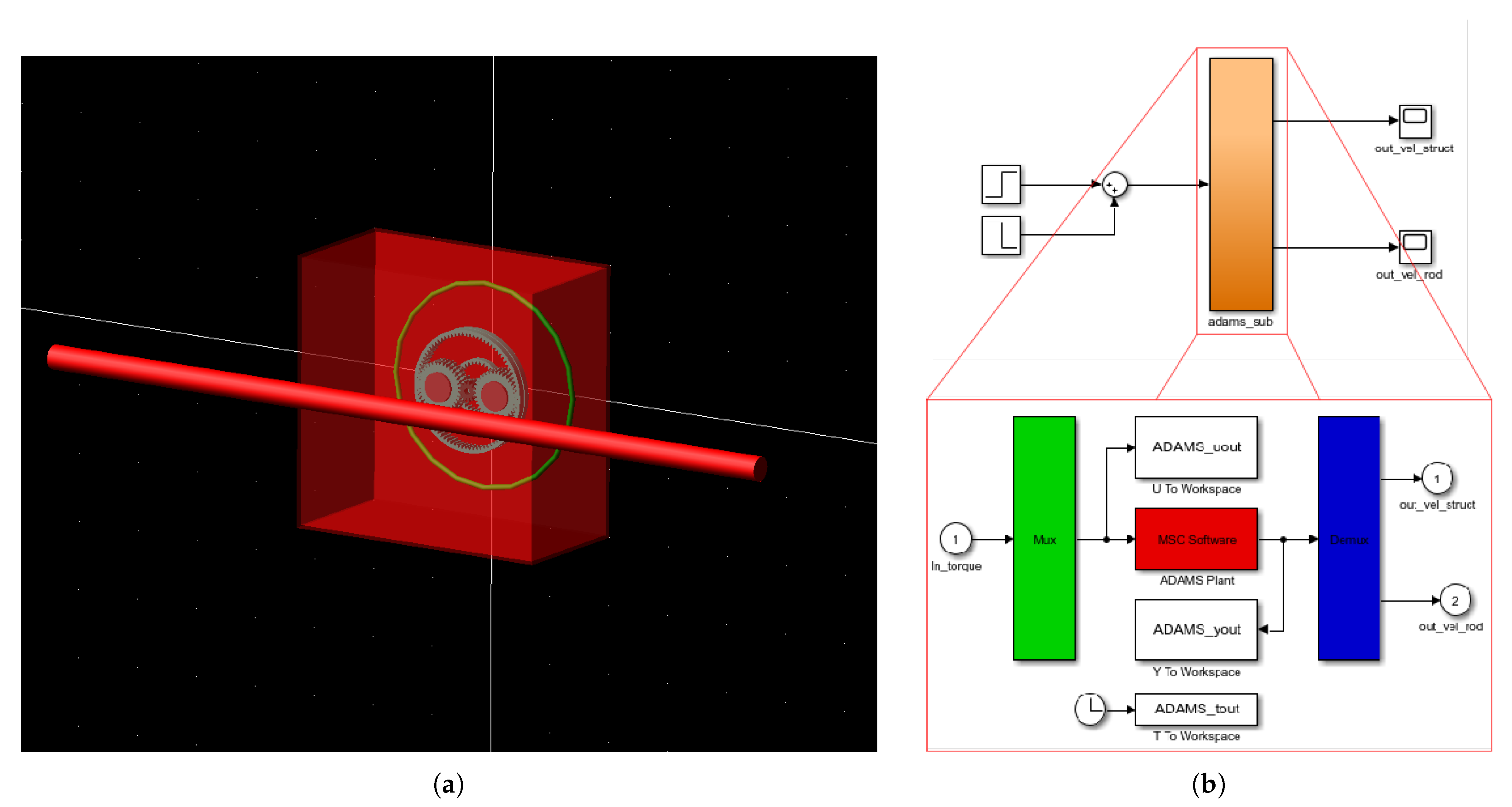
Section 3 presents the set-up of the multi-body simulation, the design of the prototype, followed by the experimental setup. In
Section 4, the results are presented and discussed. Finally, in
Section 5, the successes and drawbacks of the design are highlighted in order to further contribute to the state of the art and to build the foundation for future developments.
2. Methodology
CubeSat-type satellites are mainly used for low cost and short duration scientific missions. The low overall cost, primarily linked to the small size of the satellites themselves, is also given by the positioning of the experiment in a low Earth orbit (LEO), which defines the main operating conditions.
The design criteria and the dynamics of the PS and DBS systems are now presented.
2.1. Pointing System
The typical operating conditions of LEO orbits, summarized in
Table 1, allow us to give an estimate of the maximum angular velocity required to the
pointing system (PS). When tracking a ground object during a LEO trajectory, as depicted in
Figure 1a,
varies from a maximum value of
, relative to an orbital height
at the lower end of a LEO orbit [
33], to a minimum value of
, relative to an orbital height
. Much higher values can be reached when tracking other objects in space, i.e., other satellites. Given the maximum load angular velocity, and assuming the nominal speed of an electric motor acting on the pointing system
, it is now possible to calculate the needed value of the reduction ratio as
.
2.2. Dynamic Balancing System
The system is composed of three rigid bodies rotating of purely rotary motion around a common axis as described in
Figure 2. Therefore, the dynamics of the single rotating body is described by Euler’s dynamic equation for rotational motion [
34].
where
is the inertia tensor of the body with respect to the
body’s fixed reference frame and
is the vector of the applied torques acting on the body. Assuming that the body is rotating about the
z axis, which also corresponds to the principal axis of inertia, we can make some statements about the tensor
. First, the terms
; second, although
is to be considered time-varying with respect to a fixed coordinate system,
is instead constant in time if referred to a local coordinate system. Therefore, the inertia tensor takes the following form:
The correct functioning of the PS, coupled with the DBS, must guarantee the precise positioning of the load while keeping the attitude of the CubeSat structure unchanged. Therefore, the rotational velocity vector of the body must have the following form:
where
. Replacing Equations (
2) and (
3) in Equation (
1), the equation of motion of each rigid body rotating about the z axis is given by the following:
Equation (
4) refers to a single rigid body; therefore, in order to describe our system we introduce the following system of
ordinary differential equations (ODEs) of the second order:
where
,
and
are the inertia components along the z axis of the load, counter-rotating flywheel and structure bodies, respectively, while
and
are the torques acting between the bodies. Finally,
,
, and
are the coordinates which describe, respectively, their rotation, referring to a fixed coordinate system. In order to compute the system of equations in Equation (
5), it is necessary to indicate the relationships that link the velocities given therein.
where
represents the rotation of the load with respect to a reference system solidal to the CubeSat structure containing the PS and DBS, and
represents the rotation of the same CubeSat structure with respect to a reference frame fixed in space. Instead,
is the unknown reduction ratio that binds the CFW and the load velocities. By deriving twice Equation (
7) with respect to time, we obtain the relationships that link the accelerations of the three rigid bodies composing the system. Replacing the accelerations into Equation (
5) and imposing the equilibrium condition of the CubeSat structure, i.e.,
=
= [0 0 0], we obtain the following:
This means that the condition of dynamic balancing along the z-axis
implies that the component of the torque acting on the structure is equal to the torque acting on the load; therefore,
. A relationship is created between the first two equations in Equation (
8), obtaining the following:
Therefore, the system of rigid bodies is balanced when
. This condition is obtained whether
or the following holds:
2.3. Mechanical Reduction System
The
values, calculated in
Section 2.1 and
Section 2.2, suggest the necessity to design a high-density reduction ratio, given also the reduced internal volume available. The main mechanical reduction systems taken into consideration are the following:
Compared to spur-gear reduction systems, planetary gear systems offer, in a more compact volume, the same reduction ratios per stage. Still, in order to obtain the values shown in
Section 2.1, a certain number of reduction stages connected in series are required. Therefore, compound planetary gear transmission is the selected system for this project.
The composite planetary gearboxes are characterized by the same basic elements of the planetary gear transmission. However, the way of coupling the various parts makes these systems much more performing in terms of
while maintaining unchanged the occupied volume. The four configurations found in Ref. [
35] are called Types A, B, C, D. Type A was chosen since, with the same reduction ratio, it has the fewest moving parts.
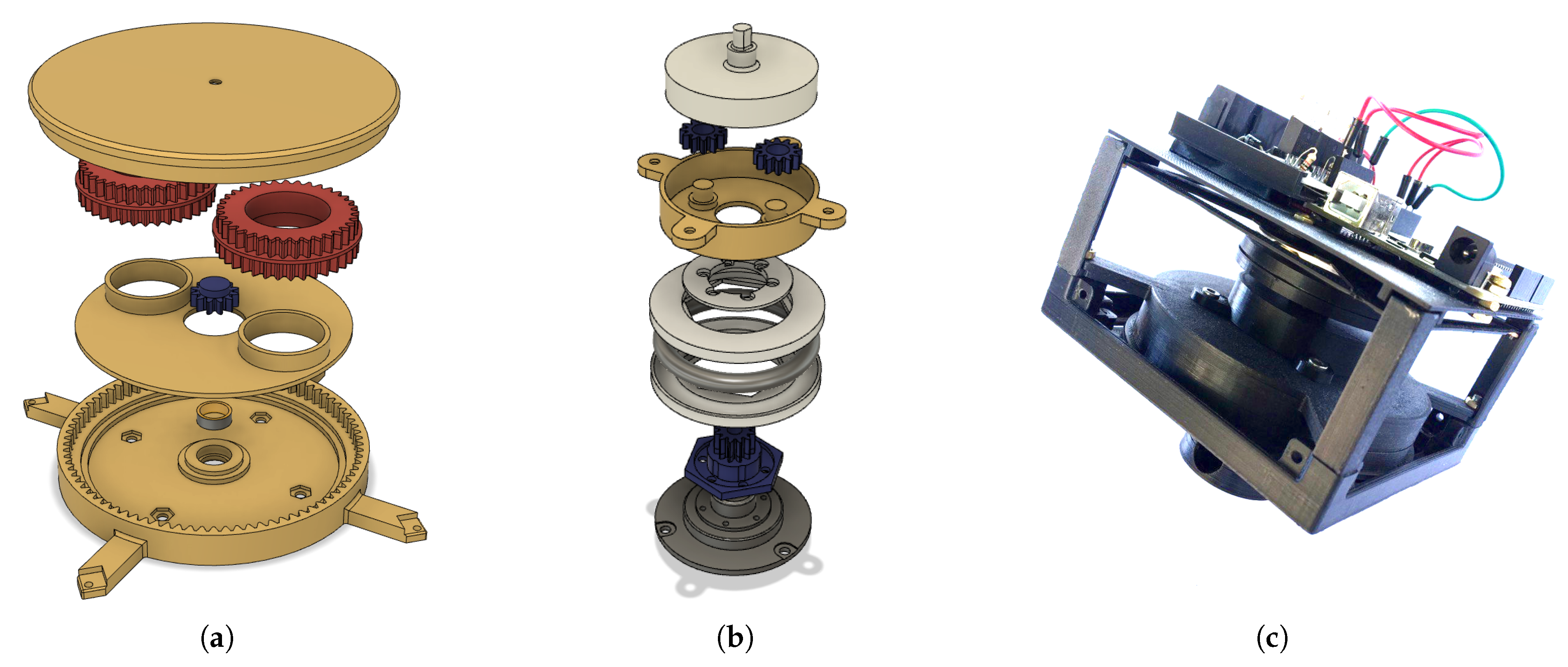
Moreover, the first stage planet gears and the second stage planet gears are directly connected, thus rotating at the same speed. The first stage ring gear is fixed, while the second stage ring gear is free to rotate, representing the output of the reduction system as shown in
Figure 3a. In order to calculate the gear setup of C-PGT, the minimum number of teeth
can be evaluated as follows:
Imposing = 10, representing the maximum reduction ratio per stage, and , the angle of pressure of the gear, is obtained. C-PGTs systems are based on planetary gears systems, and hence, two main design conditions must be met:
Condition 2:
where
n ∈
,
stands for the diameter of the gears,
z for the number of teeth and
n for the number of gears. The expression describing the reduction ratio, obtainable once values are assigned to the variables, is reported as follows:
By imposing x =
/
and y =
/
, Equation (
12) can therefore be simplified in the following:
Figure 3b shows how
is strictly dependent from
y; in fact, as
y approaches one,
rapidly increases.
Therefore, the most efficient way to increase
is to have
and
differing by one tooth. Considering the volume constraints and in compliance with the two previously reported design conditions, the reduction system setup is shown in
Table 2.
By combining the values shown in
Table 2 into Equation (
12), a reduction ratio of
is obtained. This value is not sufficient, compared to the requirements reported in
Section 2.1 and
Section 2.2. Therefore, a
PGT is installed as input to C-PGTs, obtaining a total reduction ratio of
. The minus sign suggests that the input gear rotates in an opposite direction with respect to the output ring. This condition is necessary in order to balance the total angular momentum of the system. The CFW inertia is defined by combining the load inertia values seen in
Table 2 for all configurations, with the aforementioned DB condition indicated in
Section 2.2.
2.4. Material Selection
The
fused filament fabrication (FFF) represents the most economical and perhaps diffused 3D printing technique, allowing the creation of pieces of excellent quality and high mechanical resistance. In order to establish a material’s selection criteria, a description of the requirements relative to the operating environment is needed. During each revolution around Earth, satellites are immersed in a thermal field which varies between 200
and
[
13]. At an altitude of 200 km, the atmospheric density is
, while the pressure varies between
mbar and
mbar on the outside and on the inside of the satellite, respectively. These high vacuum conditions cause
outgassing; additionally, for the same reason, the use of greases and oil for lubrication must be avoided.
Four main material characteristics, along with their constraint value, compose the selection criteria needed to determine the most suitable printing material for our intent: low static and dynamic friction coefficients (
), resistance to
outgassing (
), high mechanical strength (
) and a wide range of thermal resistance
CUT. In
Table 3, all printing materials suited for FFF are listed along with their main characteristics. Given the wide range of choice, two different group materials are selected: one for the CubeSat structure, and one for the C-PGT.
Considering the selection criterion parameters, the optimal printable materials are reported in
Table 4 along with their main technical characteristics.
The CubeSat structure must endure the toughest conditions; because of this, the selected materials are PEEK and PEI, indicated by their commercial names ANTERO and ULTEM, respectively. Instead, the PS is positioned inside the CubeSat structure together with the control boards, the inertia disk and the electric motor. Being shielded from direct sun radiation exposure translates into a narrower temperature range, compared to external conditions. Normally, gearboxes are lubricated by means of specific oils or greases in order to reduce friction and wear between the parts and to dissipate heat. However, common lubricants cannot be used in space, due to susceptibility to low-pressure evaporation. As such, low-friction materials () with good values of are promising candidates; PA, PETG and POM are identified as the best amongst those considered in this study: iglidur, ™ and POM-C, respectively.
Having already fixed the gears characteristics, setting the
polylactic acid (PLA) as the prototype printing material and considering also the maximum mechanical stresses present in the C-PGT, we proceeded in accordance with the theory concerning 3D-printed spur gears [
23,
24,
36], imposing an optimal thickness (
) common to all gears, useful to provide a certain safety margin. The reduction system was then modeled using Fusion 360
® software, paying attention to the constraints given by the containment structure.
2.5. Motor Control System
Actuators in space are usually classified as active and passive. Passive systems are those operated by spring mechanisms, i.e., deployment systems, while active systems are those operated by electric motors and related control electronics [
32,
37,
38]. The selection of the motor was based on considerations regarding the high-vacuum environment found in orbit [
39]. Taking
brushed motors,
stepper motors and
brushless motors (BLDC) into consideration, the optimal choice for our purpose fell on BLDC motors. The choice was justified by the greater reliability and excellent ratio between the weight and torque generated. In order to set up and test the prototype, a simple open loop speed control is designed. An electronic speed control (ESC), composed by three TIP122G transistors, three 1N5817 schottky diodes and three 1k resistors is assembled. The control software is composed of a loop cycle that controls the motor phases excitation time, starting from a maximum value of
to
in a period of
. Once
is reached, the activation time profile is kept constant. In order to convert the time steps in the rotational speed of the payload, the following equation is used:
where the only unknown parameter is
, representing the number of motor poles.
4. Results and Discussion
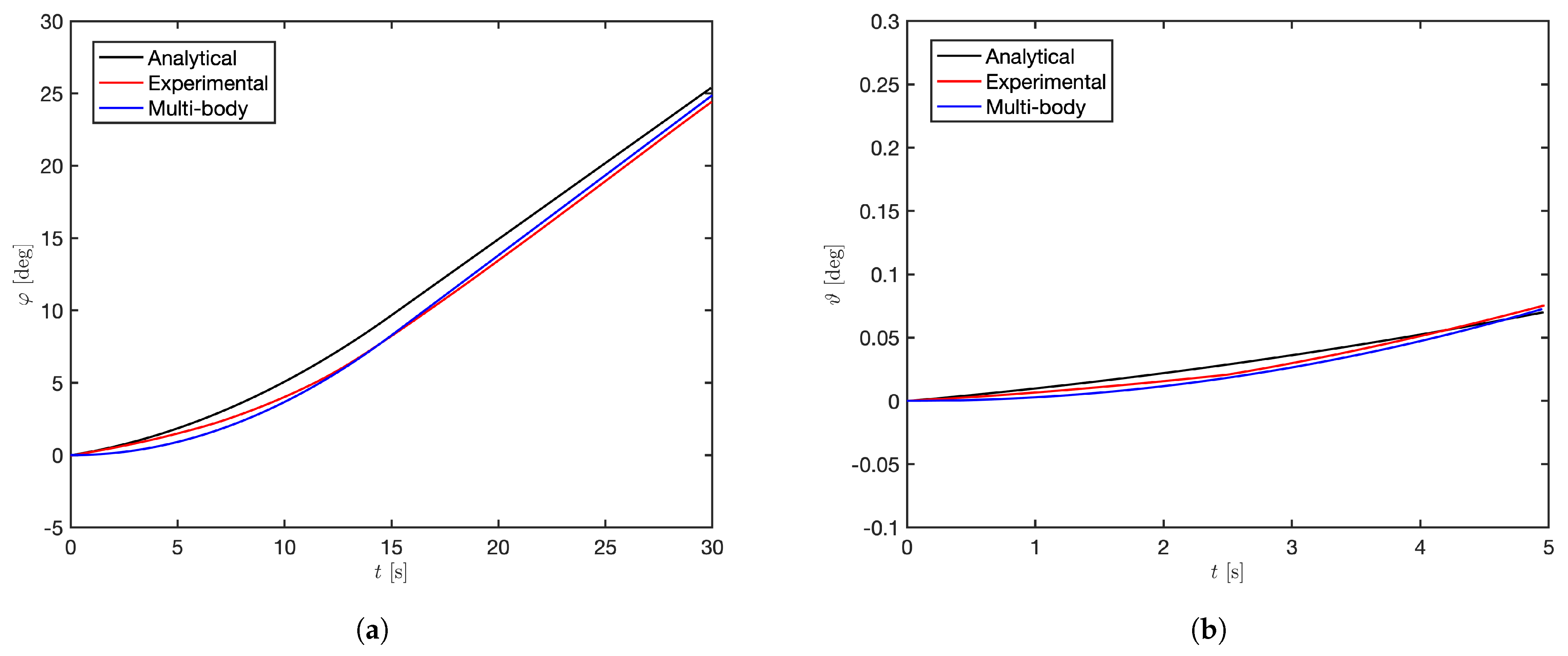
The PS experimental test results, along with the data obtained by the multi-body and analytical models are shown in
Figure 7a and
Figure 8a, and in
Table 7. The plots in
Figure 7a compare the functions
obtained from the analytical model and those from the multi-body simulation, with the experimental data extracted from the videos of the experimental campaign, captured using the
image processing toolbox. The highest load displacement values, corresponding to
are reported in
Table 7. The analytical model reaches the maximum displacement of
. This shows a slightly different trend with respect to the experimental
and the multi-body simulation that, instead, reaches a value of
°. It is clear that between the two models, the one that mostly adheres to the experimental data is the multi-body. This result highlights the better capability of ADAMS in predicting the dynamic variables trend. In
Figure 8a, the comparison between the experimental data for the balanced (B) and an unbalanced (U) PS is shown.The experimental absolute angular position for the unbalanced solution diverges rapidly with respect to the balanced case, reaching a value of angular displacement
, almost 5 times higher than the nominal value of
. It is worth noting that a value so high is given by the small satellite payload inertia involved in the experimental test, compared to the sources of error (e.g., gearbox). In a real setup, such as that shown in
Figure 1b, where the fixed side is composed of three aligned CubeSats units, we expect
to be considerably narrower.
Another fundamental parameter which was considered in the experimental campaign is the payload angular velocity. The maximum relative angular velocity is
, a value which is within the required speed range set in
Section 2.1, and corresponds to the value imposed by means of Equation (
14), thus proving the efficiency of the actuator and the accuracy of its open loop control system.
The DBS experimental results are shown in
Figure 7b and
Figure 8b, and in
Table 7.
Figure 7b compares
(t), obtained in the experimental campaign with full load inertia, with the analytical and multi-body models. The model that most adheres to the experimental results for what concerns to the PS is that which is obtained with the multi-body simulation. In
Figure 8b, we highlight the difference between the experimental results for the balanced
and unbalanced
solution. In the first
of simulation, the dynamically balanced prototype reaches the maximum displacement of
=
, maintaining the structure attitude along the
z axis, being fairly unchanged, while the unbalanced prototype reaches the maximum displacement of
. These results show the vital importance of a correctly designed DBS; the two experimental results, in fact, differ by two orders of magnitude. The results obtained for the balanced solution prove also the correctness of the mechanical reduction system design.
Moreover, the experimental results show a remarkable adherence of the analytical and numerical models with the experimental results. The small differences can be ascribable to many factors, such as friction, poor clearance between moving 3D-printed parts, or the approximations used in the definition of the inertia parameters.
The experimental campaign has, therefore, successfully verified the correct functioning of the proposed PS. The system is suitable for rotating at least a 3U CubeSat, within the speed range established in
Section 2.2. In addition, the FFF printing technique has produced a prototype with accurate precision, especially for what concerns the parts present within the reduction system, being able to withstand the mechanical stresses generated during the test, even with a low-performance material such as PLA.
Furthermore, during the experiments, the effectiveness of the DBS was proven; in its absence, the correct positioning of the load would be impossible without ACS to compensate. In fact, it is seen how the presence of the CFW, combined with a high-density reduction system, such as the C-PGTs, allows to greatly reduce the rotations of the overall structure, leaving only the small final corrections to the ACS.
5. Conclusions
In this work, we tested a different designing and manufacturing approach to the realization of a vital component of CubeSat satellites: the pointing system (PS). The PS is capable of rotating a payload composed by a certain number of CubeSat units, and was designed and tested along with an integrated dynamic balancing system, both operated by the same brushless DC motor. The choice of incorporating a dynamic balancing system (DBS) directly in the PS avoids the necessity to have a dedicated electronic control board for the dynamic balance of the satellite. However, we are aware that an attitude control system is still useful for small attitude corrections. Going further, adapting to the Cubesat satellite philosophy and focusing on the economy of bulk space and weights, we have designed the whole system in order to be 3D printed and installed inside a half-unit module. To this end, we paid particular attention to the type of infill pattern to be used for the realization of our prototype. In fact, it is well known that by using an infill pattern, it is possible to achieve the same or even better mechanical properties than a solid printed piece, with a consequent saving of material and therefore of weight [
40]. Among the various types of pattern available, we preferred the “Gyroid” type because in addition to having significant vibration absorption properties, it is 23.7% faster and up to 12.59% more resistant in terms of tensile strength, compared to a “honeycomb” infill type [
41].
In
Section 2.4, the research of AM compatible materials suitable for the difficult operational conditions of the LEO orbits allowed us to determine the best candidates, such as PEEK and PEI for the CubeSat structure, where the thermal and mechanical stresses dictate the material characteristic requests. On the other hand, POM, PETG and Igildur were identified as candidates for the PS mechanical reduction system, where, in addition to the aforementioned requirements, the auto lubrication of the moving parts is needed. However, our materials research did not consider issues related to the effects of gamma rays. The materials selected by us, suitable to withstand thermal conditions, outgassing and mechanical stress, must be specially coated so as not to degrade, due to the rays themselves. In order to verify the design, a PLA prototype was fabricated and tested along with its actuation system. This proved the correct functioning of the PS and DBS design, and the advantage of additive manufacturing, such as good dimensional accuracy and reduced weight of the components (the 1/2 u CubeSat along with the PS and DBS weighs no more than
, comprehensive of the electronic board and BLDC motor).
Given the results obtained on the prototype, we believe that AM is suited for the creation of satellite parts as complex as the reduction system designed in this work. In addition, the possibility of producing components directly in orbit—for example, on the ISS—would allow the rapid creation and modification of parts without having to wait for supplies from the ground. Moreover, we can avoid subjecting the most delicate parts to mechanical stress due to the launch. In fact, the realization via AM of a functioning CubeSat directly on ISS, printed and assembled by astronauts, is not a novelty as demonstrated in the MakerSat-1 mission [
42].


