
Engineering Interoperable, Plug-and-Play, Distributed, Robotic Control Systems for Futureproof Fusion Power Plants

 , and
, and
Abstract
:1. Introduction
2. Background
3. Control of the TARM Robot as a Case Study for the CorteX Control System
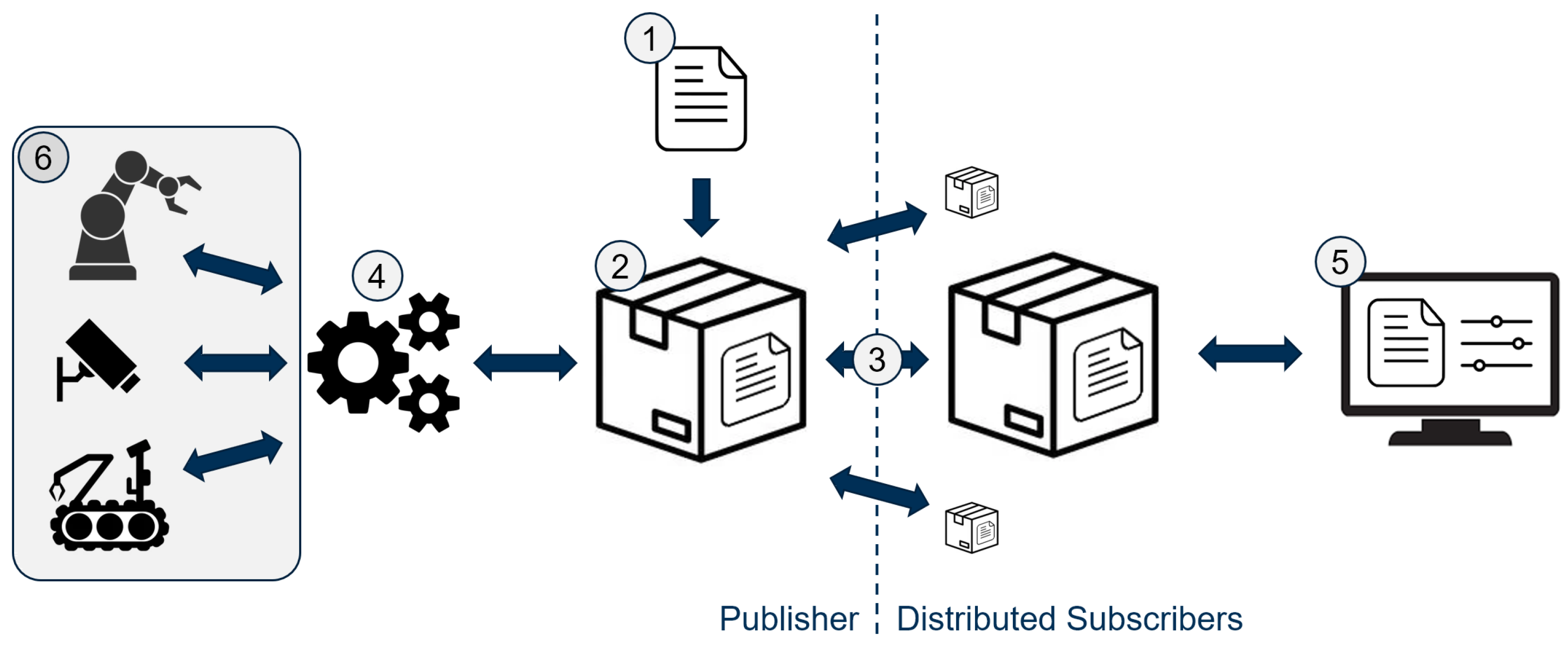
3.1. CorteX Design
- A standard way of describing systems.
- A software implementation of this standard.
- A scalable communication interface.
- An extension to facilitate the control of these systems.
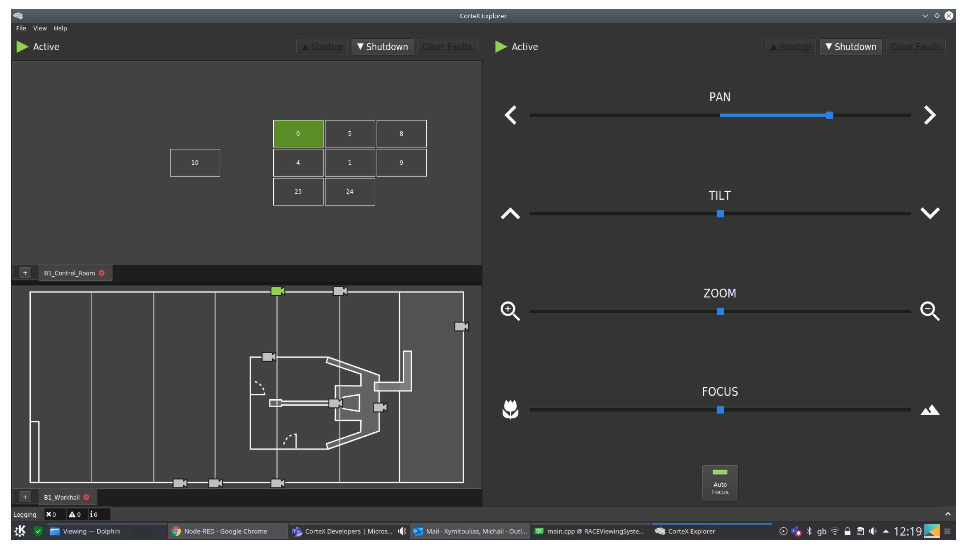
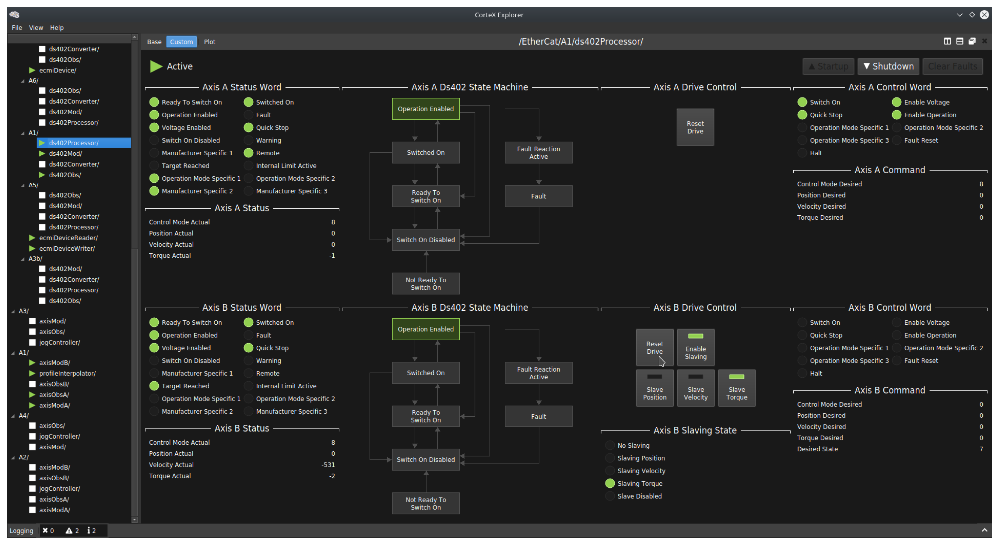
- A graphical user interface for operating these systems.
- A framework to facilitate the extension and expansion of these systems (e.g., hardware interfaces).
3.1.1. CorteX Quality Assurance
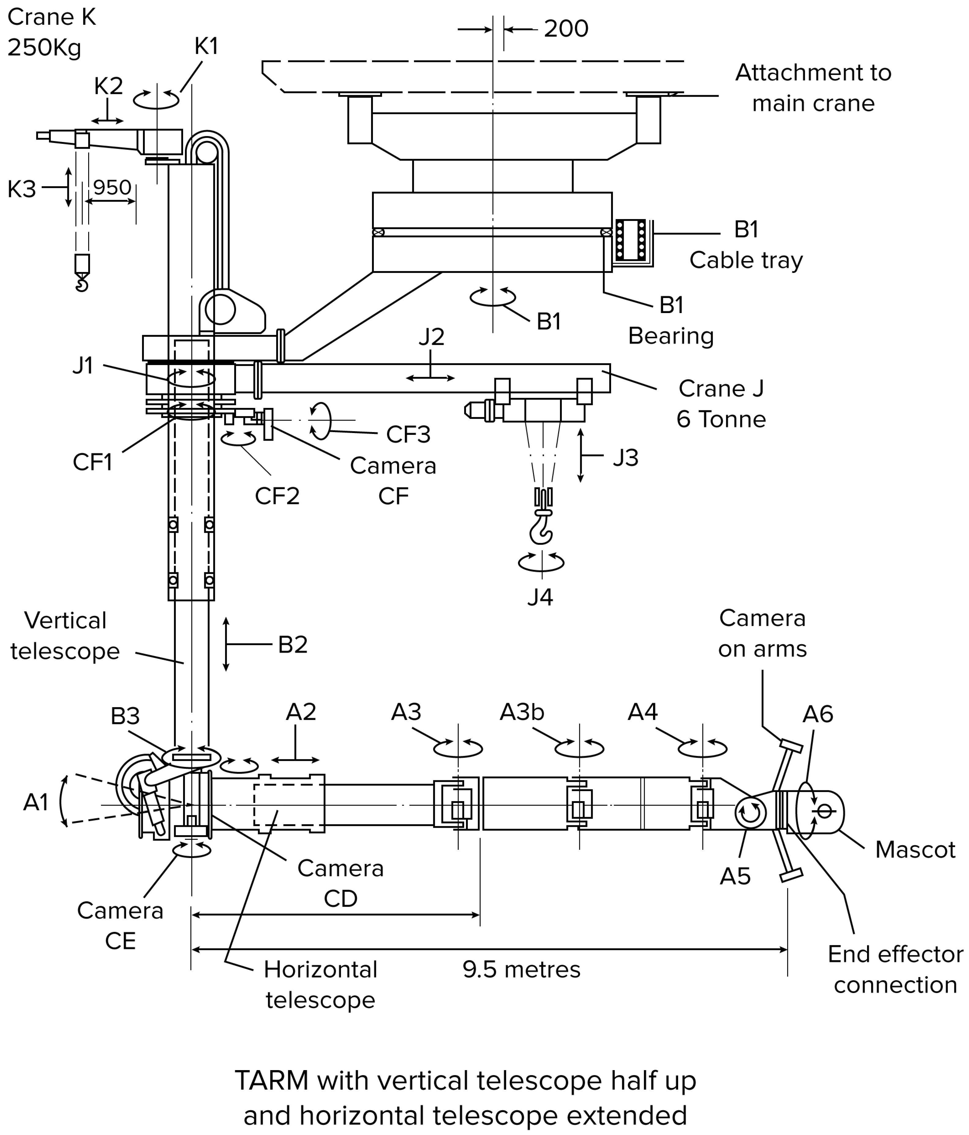
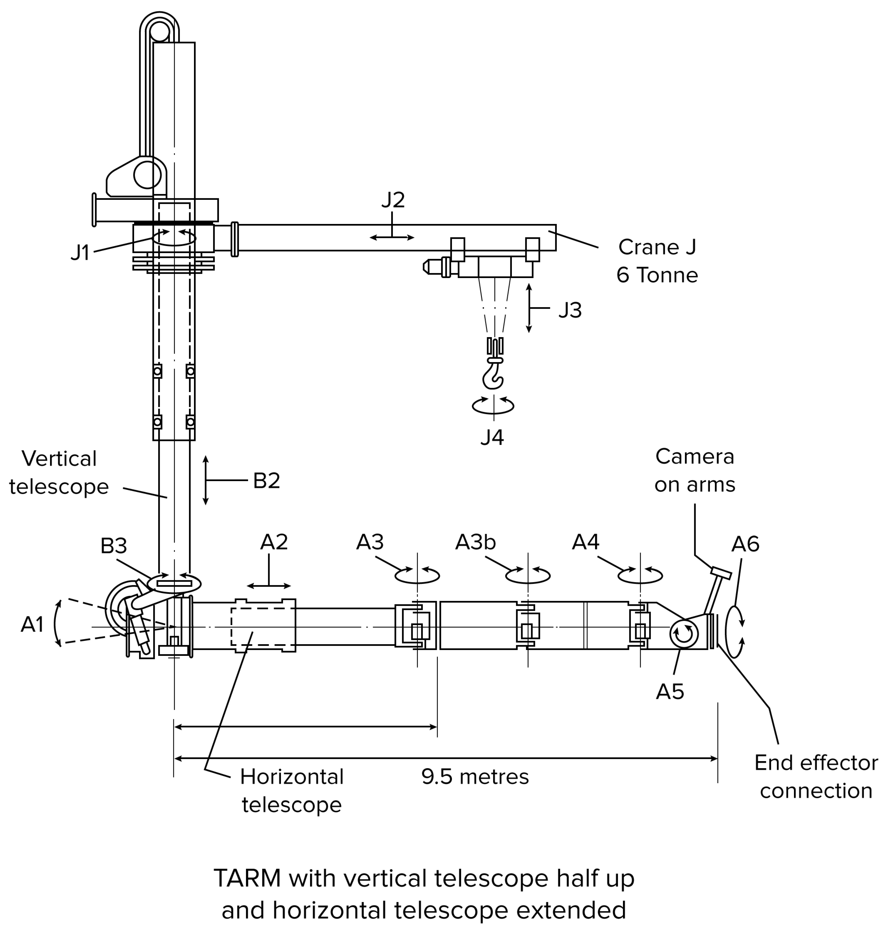
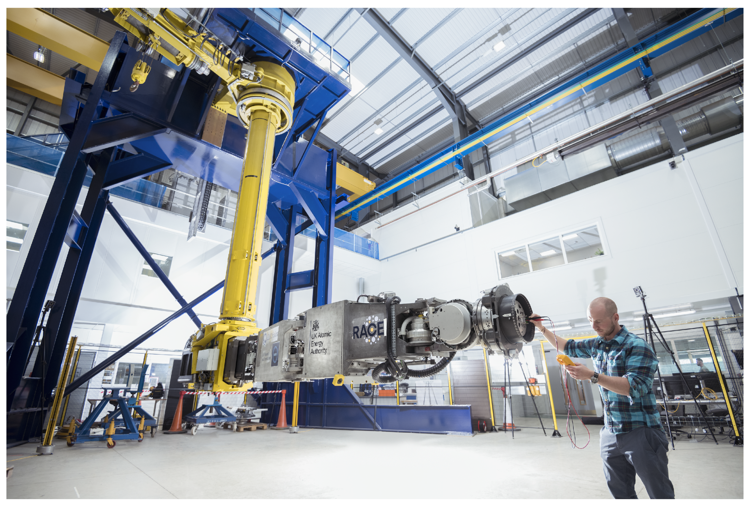
3.2. TARM
4. Experimental Setup and Performance Evaluation
4.1. Experimental Setup
4.2. TARM Performance Evaluation
5. Conclusions
Author Contributions
Funding
Institutional Review Board Statement
Informed Consent Statement
Data Availability Statement
Acknowledgments
Conflicts of Interest
References
- Team, J. Fusion energy production from a deuterium-tritium plasma in the JET tokamak. Nucl. Fusion 1992, 32, 187. [Google Scholar] [CrossRef] [Green Version]
- Quigley, M.; Conley, K.; Gerkey, B.; Faust, J.; Foote, T.; Leibs, J.; Wheeler, R.; Ng, A.Y. ROS: An open-source Robot Operating System. In Proceedings of the ICRA Workshop on Open Source Software, Kobe, Japan, 12 May 2009; Volume 3, p. 5. [Google Scholar]
- Maruyama, Y.; Kato, S.; Azumi, T. Exploring the performance of ROS2. In Proceedings of the 13th International Conference on Embedded Software, Pittsburgh, PA, USA, 1–7 October 2016; pp. 1–10. [Google Scholar]
- Schlesselman, J.M.; Pardo-Castellote, G.; Farabaugh, B. OMG data-distribution service (DDS): Architectural update. In Proceedings of the IEEE MILCOM 2004, Military Communications Conference, Monterey, CA, USA, 31 October–3 November 2004; Volume 2, pp. 961–967. [Google Scholar]
- Henssen, R.; Schleipen, M. Interoperability between OPC UA and AutomationML. Procedia CIRP 2014, 25, 297–304. [Google Scholar] [CrossRef]
- Banks, A.; Gupta, R. MQTT Version 3.1.1. OASIS Stand. 2014, 29, 89. [Google Scholar]
- Henning, M.; Spruiell, M. Distributed programming with ice. ZeroC Inc. Rev. 2003, 3, 97. [Google Scholar]
- Createc Robotics IRIS. Available online: https://www.createcrobotics.com/ (accessed on 28 May 2021).
- Barr, D. Supervisory Control and Data Acquisition (SCADA); Systems National Communications System, Communication Technologies: Arlington, VA, USA, 2004. [Google Scholar]
- Profanter, S.; Tekat, A.; Dorofeev, K.; Rickert, M.; Knoll, A. OPC UA versus ROS, DDS, and MQTT: Performance evaluation of industry 4.0 protocols. In Proceedings of the 2019 IEEE International Conference on Industrial Technology (ICIT), Melbourne, VIC, Australia, 13–15 February 2019; pp. 955–962. [Google Scholar]
- Cabrera, E.J.S.; Palaguachi, S.; León-Paredes, G.A.; Gallegos-Segovia, P.L.; Bravo-Quezada, O.G. Industrial Communication Based on MQTT and Modbus Communication Applied in a Meteorological Network. In The International Conference on Advances in Emerging Trends and Technologies; Springer: Cham, Switzerland, 2020; pp. 29–41. [Google Scholar]
- Mühlbauer, N.; Kirdan, E.; Pahl, M.O.; Waedt, K. Feature-based Comparison of Open Source OPC-UA Implementations. In Proceedings of the INFORMATIK 2020, Karlsruhe, Germany, 28 September–2 October 2020. [Google Scholar]
- Silva, D.; Carvalho, L.I.; Soares, J.; Sofia, R.C. A Performance Analysis of Internet of Things Networking Protocols: Evaluating MQTT, CoAP, OPC UA. Appl. Sci. 2021, 11, 4879. [Google Scholar] [CrossRef]
- Caliskanelli, I.; Goodliffe, M.; Whiffin, C.; Xymitoulias, M.; Whittaker, E.; Verma, S.; Hickman, C.; Minghao, C.; Skilton, R. CorteX: A Software Framework for Interoperable, Plug-and-Play, Distributed, Robotic Systems of Systems. In Software Engineering for Robotics; Springer: Cham, Switzerland, 2021; pp. 295–344. [Google Scholar]
- Burroughes, G.; Jonathan, K.; Matt, G.; David, M.-G.; Alexandrine, K.; Ed, C.; Steve, G.; Antony, L.; Rob, B. Precision Control of a Slender High Payload 22 DoF Nuclear Robot System: TARM Re-Ascending; International Atomic Energy Agency (IAEA) Vienna International Centre: Vienna, Austria, 2018. [Google Scholar]
- Hamilton, D.; Preece, G. Development of the MASCOT Telemanipulator Control System; European Fusion Development Agreement Project; EFDA, Culham Science Centre: Abingdon, UK, 2001. [Google Scholar]
- Snoj, L.; Lengar, I.; Cufar, A.; Syme, B.; Popovichev, S.; Conroy, S.; Meredith, L.; Contributors, J.E. Calculations to support JET neutron yield calibration: Modelling of the JET remote handling system. Nucl. Eng. Des. 2013, 261, 244–250. [Google Scholar] [CrossRef]


| Joint | Pose | Link | Cartesian Position—World Frame (mm) | Max Diff. | ||||||||||
|---|---|---|---|---|---|---|---|---|---|---|---|---|---|---|
| Axis | Iteration 1 | Iteration 2 | Iteration 3 | Iteration 4 | Iteration 5 | |||||||||
| Forward | Reverse | Forward | Reverse | Forward | Reverse | Forward | Reverse | Forward | Reverse | |||||
| - | Home | A6 | X Y Z | −275 5515 1242 | −277 5515 1242 | −277 5515 1242 | −277 5515 1242 | −277 5515 1242 | −277 5515 1242 | 2 0 0 | ||||
| A3b Link | X Y Z | −175 2455 1692 | −176 2455 1692 | −176 2455 1692 | −176 2455 1692 | −176 2455 1692 | −177 2455 1692 | 2 0 0 | ||||||
| A3 Link | X Y Z | −104 397 1685 | −104 397 1685 | −104 397 1685 | −104 397 1685 | −104 397 1685 | −104 397 1685 | 0 0 0 | ||||||
| A2 | X Y Z | −102 398 1685 | −102 398 1685 | −102 398 1685 | −102 398 1685 | −102 398 1685 | −102 398 1685 | 0 0 0 | ||||||
| A3 | −0.1 rad | A6 | X Y Z | −780 5471 1239 | −781 5471 1239 | −781 5471 1240 | −781 5471 1240 | −781 5472 1240 | −781 5472 1240 | −781 5471 1240 | −781 5471 1240 | −781 5471 1240 | −781 5472 1240 | 1 1 1 |
| A3b Link | X Y Z | −376 2437 1691 | −377 2437 1691 | −377 2437 1691 | −377 2437 1691 | −377 2437 1691 | −377 2437 1691 | −377 2437 1691 | −377 2437 1691 | −377 2437 1691 | −377 2437 1691 | 1 0 0 | ||
| A3 Link | X Y Z | −100 396 1685 | −101 396 1685 | −101 396 1685 | −100 396 1685 | −101 396 1685 | −101 396 1685 | −101 396 1685 | −100 396 1685 | −101 396 1685 | −101 396 1685 | 1 0 0 | ||
| A2 | X Y Z | −102 398 1685 | −102 398 1685 | −102 398 1685 | −102 398 1685 | −102 398 1685 | −102 398 1685 | −102 398 1685 | −101 398 1685 | −101 398 1685 | −101 398 1685 | 1 0 0 | ||
| A4 | 1.48 rad | A6 | X Y Z | 302 4732 1247 | 301 4732 1248 | 301 4732 1248 | 301 4733 1248 | 301 4733 1248 | 301 4733 1248 | 301 4733 1248 | 301 4732 1248 | 301 4732 1248 | 301 4733 1248 | 1 1 1 |
| A3b Link | X Y Z | −376 2437 1691 | −377 2437 1692 | −376 2437 1692 | −377 2437 1691 | −377 2437 1691 | −377 2437 1691 | −377 2437 1692 | −377 2437 1692 | −377 2437 1692 | −377 2437 1692 | 1 0 1 | ||
| A3 Link | X Y Z | −100 396 1685 | −101 396 1685 | −101 396 1685 | −101 396 1685 | −101 396 1685 | −101 396 1685 | −101 396 1685 | −101 396 1685 | −101 396 1685 | −101 396 1685 | 1 0 0 | ||
| A2 | X Y Z | −102 398 1685 | −102 398 1685 | −102 398 1685 | −102 398 1685 | −102 398 1685 | −102 398 1685 | −102 398 1685 | −102 398 1685 | −102 398 1685 | −101 398 1685 | 1 0 0 | ||
| A3b | −1.36 rad | A6 | X Y Z | −2447 3588 1239 | −2447 3588 1239 | −2447 3588 1239 | −2447 3588 1239 | −2447 3588 1239 | −2447 3588 1239 | −2447 3588 1239 | −2447 3588 1239 | −2447 3588 1239 | −2447 3588 1239 | 0 0 1 |
| A3b Link | X Y Z | −347 2451 1694 | −347 2451 1694 | −347 2450 1694 | −347 2450 1694 | −347 2450 1694 | −347 2450 1694 | −347 2450 1694 | −347 2450 1694 | −347 2450 1694 | −347 2450 1694 | 0 1 0 | ||
| A3 Link | X Y Z | −101 397 1686 | −101 397 1686 | −101 397 1686 | −101 397 1686 | −101 397 1686 | −101 397 1686 | −101 397 1686 | −101 397 1686 | −101 397 1686 | −101 397 1686 | 0 0 0 | ||
| A2 | X Y Z | −101 399 1686 | −101 399 1686 | −101 398 1686 | −101 399 1686 | −101 399 1686 | −101 399 1686 | −101 399 1686 | −101 398 1686 | −101 398 1686 | −101 398 1686 | 0 1 0 | ||
| A2 | 2.90 m | A6 | X Y Z | −2573 6313 1189 | −2573 6316 1189 | −2573 6316 1189 | −2573 6316 1189 | −2573 6316 1189 | 0 3 0 | |||||
| A3b Link | X Y Z | −472 5180 1654 | −472 5180 1654 | −473 5180 1654 | −472 5180 1654 | −473 5180 1654 | 1 0 0 | |||||||
| A3 Link | X Y Z | −226 3125 1658 | −226 3125 1658 | −226 3125 1658 | −226 3125 1658 | −226 3125 1658 | 0 0 0 | |||||||
| A2 | X Y Z | −225 3127 1658 | −225 3127 1658 | −224 3127 1658 | −224 3127 1658 | −224 3127 1658 | 1 0 0 | |||||||
Publisher’s Note: MDPI stays neutral with regard to jurisdictional claims in published maps and institutional affiliations. |
© 2021 by the authors. Licensee MDPI, Basel, Switzerland. This article is an open access article distributed under the terms and conditions of the Creative Commons Attribution (CC BY) license (https://creativecommons.org/licenses/by/4.0/).
Share and Cite
Caliskanelli, I.; Goodliffe, M.; Whiffin, C.; Xymitoulias, M.; Whittaker, E.; Verma, S.; Skilton, R. Engineering Interoperable, Plug-and-Play, Distributed, Robotic Control Systems for Futureproof Fusion Power Plants. Robotics 2021, 10, 108. https://doi.org/10.3390/robotics10030108
Caliskanelli I, Goodliffe M, Whiffin C, Xymitoulias M, Whittaker E, Verma S, Skilton R. Engineering Interoperable, Plug-and-Play, Distributed, Robotic Control Systems for Futureproof Fusion Power Plants. Robotics. 2021; 10(3):108. https://doi.org/10.3390/robotics10030108
Chicago/Turabian StyleCaliskanelli, Ipek, Matthew Goodliffe, Craig Whiffin, Michail Xymitoulias, Edward Whittaker, Swapnil Verma, and Robert Skilton. 2021. "Engineering Interoperable, Plug-and-Play, Distributed, Robotic Control Systems for Futureproof Fusion Power Plants" Robotics 10, no. 3: 108. https://doi.org/10.3390/robotics10030108
APA StyleCaliskanelli, I., Goodliffe, M., Whiffin, C., Xymitoulias, M., Whittaker, E., Verma, S., & Skilton, R. (2021). Engineering Interoperable, Plug-and-Play, Distributed, Robotic Control Systems for Futureproof Fusion Power Plants. Robotics, 10(3), 108. https://doi.org/10.3390/robotics10030108