Article

Paquitop.arm, a Mobile Manipulator for Assessing Emerging Challenges in the COVID-19 Pandemic Scenario

Department of Mechanical and Aerospace Engineering, Politecnico di Torino, 10129 Torino, Italy
*
Authors to whom correspondence should be addressed.
Robotics 2021, 10(3), 102; https://doi.org/10.3390/robotics10030102
Submission received: 29 June 2021 / Revised: 10 August 2021 / Accepted: 11 August 2021 / Published: 14 August 2021
(This article belongs to the Special Issue Service Robotics against COVID-2019 Pandemic)

Abstract

:
The use of automation and robotics technologies for caregiving and assistance has become a very interesting research topic in the field of robotics. The spread of COVID-19 has highlighted the importance of social distancing in hospitals and health centers, and collaborative robotics can bring substantial improvements in terms of sparing health workers basic operations. Thus, researchers from Politecnico di Torino are working on Paquitop.arm, a mobile robot for assistive tasks. The purpose of this paper is to present a system composed of an omnidirectional mobile platform, a 6 DOF robot arm, and a depth camera. Task-oriented considerations are made to estimate a set of mounting parameters that represents a trade-off between the exploitation of the robot arm workspace and the compactness of the entire system. To this end, dexterity and force transmission indexes are introduced to study both the kinematic and the static behavior of the manipulator as a function of the mounting parameters. Finally, to avoid singularities during the execution of the task, the platform approach to the task workspaces is studied.

1. Introduction

In the last decades, many researchers in the robotic field have investigated assistive robotics, developing several mobile robotic platforms conceived to help weak or non-self-sufficient subjects [1,2,3]. The recent COVID-19 pandemic has revealed the importance of social distancing, especially in those structures, such as geriatric wards and hospices, where patients are endangered by closeness to other people [4]. Although human care cannot be replaced entirely (e.g., for complex operations and companionship), properly conceived and instrumented robots can be entrusted with other duties. Blood pressure, temperature, and oxygen saturation measurements, patient monitoring, or simply providing a connectivity platform for remote communication are some examples of tasks that could be easily assessed without the presence of humans. Moreover, an unprecedented decrease in mortality and fertility rates in industrialized countries has resulted in the general ageing of the population. These phenomena have led the community of robotics researchers to focus its attention on meeting the ever-growing demand for health care, housing, and caregiving. Pursuing this objective automatically implies a variety of technical challenges. A large amount of work has been done in the field, and the literature is rich especially for wheeled mobile robots [5]. Mechanical design [6], navigation, and motion planning [7], as well as safety-related control strategies for human–robot interaction [8], are few examples of interesting research conducted in the field. In the past, the class of differential drive robots [9] was exploited more than others for domestic use because of their simplicity and low cost. Nonetheless, their limited maneuverability makes them less attractive for applications in which a superior orientation ability is required. To obtain high maneuverability, most devices are provided with a redundant actuation, which gives them the ability to perform omnidirectional motions in the plane. For example, a widely used approach of redundant locomotion involves omni-wheels, whose correct functioning strictly depends on the evenness of the ground and on the materials of which they are made [10]. These are the premises that led researchers at Politecnico di Torino to develop an innovative mobile platform, named Paquitop [11,12], as the base modular frame for indoor robotized assistance applications. The base platform is suspended on four wheels: two of them are driven steering wheels, while two are standard off-centered passive castor wheels. Due to its particular workspace, the robot is shaped on a human scale to access all spaces which are usually inhabited by persons. Therefore, a non-axisymmetric footprint has been adopted so that the robot can offer a reduced size to pass through confined spaces. The kinematics of the platform has been deeply investigated by the authors in [12], while suspension design guidelines were presented in [13,14]. In these works, dynamic analyses were conducted to investigate the response of the platform to obstacles laying on the ground. The results showed that the suspension layout plays a role with crucial importance in attaining a non-trivial tradeoff among two opposite needs: reducing the pitch–roll rotations of the chassis and guaranteeing a fast suppression of the vertical oscillations caused by small obstacles. Among the proposed layouts, a single-arm configuration was identified as optimal for pitch–roll assessment. Unfortunately, this configuration is not optimal for overpassing obstacles, although this a disadvantage can be addressed with a properly conceived obstacle-approach strategy that prevents the robot from engaging an obstacle with the two driven wheels simultaneously. Finally, a preliminary analysis for the implementation of a robotic arm on the Paquitop platform, named Paquitop.arm, was proposed by the authors of [15].

1.1. Description of Paquitop.arm Prototype

The updated prototype of Paquitop.arm includes a robotic arm manipulator to allow the platform to enhance the machine’s capability to interact with its surroundings and perform assistive tasks. The chosen manipulator is the 6 DOF Kinova Gen3 Lite, with a reach of 1 m, a nominal payload of 0.5 kg, and an overall mass of 5.2 kg. As shown in Figure 1a, the collaborative robot is installed on a mounting structure that enables different mounting configurations.
Aside from providing sufficient mechanical resistance to the static and dynamic inputs coming from the system’s motion, the structure must position the arm base so that the equilibrium of the system is as independent as possible from the co-bot posture. This fact is of great importance as the Paquitop platform and manipulator masses are comparable; thus, the center of mass of the system strictly depends on the robot mounting position and orientation. To ensure the static stability of the entire Paquitop.arm system, its center of mass projection must be inside its support polygon [16,17]. Notice that the configuration of the four wheels leads to a rhombic shape of the polygon, with the axis aligned with the major and minor axes of the platform, as presented and discussed below.
In Figure 1b, the main reference frames of Paquitop.arm are defined. The position and orientation of the mobile platform with respect to a fixed reference frame (r.f.) { s } is defined through the r.f. { c } , fixed to the platform and positioned in the center of the elliptical footprint at ground level. Moreover, r.f. { 0 } represents the base frame of the robotic arm, while { e } is the end-effector r.f. The missing axes are oriented according to the right-hand rule.
Upon the mounting structure, the manipulator can be fixed with a variable decentration along the major axis of the elliptic platform to allow the robot to reach the desired tasks more efficiently and to take advantage of free space left on the platform, which can be used to store objects or to mount additional components.
Notice that no decentration along the minor axis has been considered because the center of mass will easily reach the polygon edge even with a small decentration.
The use of a decentration and an orientation with respect to the platform’s geometrical center also helps to keep the robotic system far from singular configurations (which take place when the instantaneous center of rotation of the mobile base lies on the axis of the arm first joint; see [15] for further details) and provides it with a redundant degree of freedom. From the point of view of position kinematics, then, dealing with a redundant manipulator instead of a classic one allows many issues typical of collaborative applications to be approached in a more efficient way, such as that of obstacle avoidance. This point is deeply investigated in [15], in which the effect of the mobile platform position and orientation with respect to the manipulation target are parametrically analyzed. In that work, it was preliminarily shown that the range of possible configurations available for obstacle avoidance varies with the mounting configuration of the arm and that such configurations can be exploited by modifying the mutual pose of the mobile robot with respect to the target.

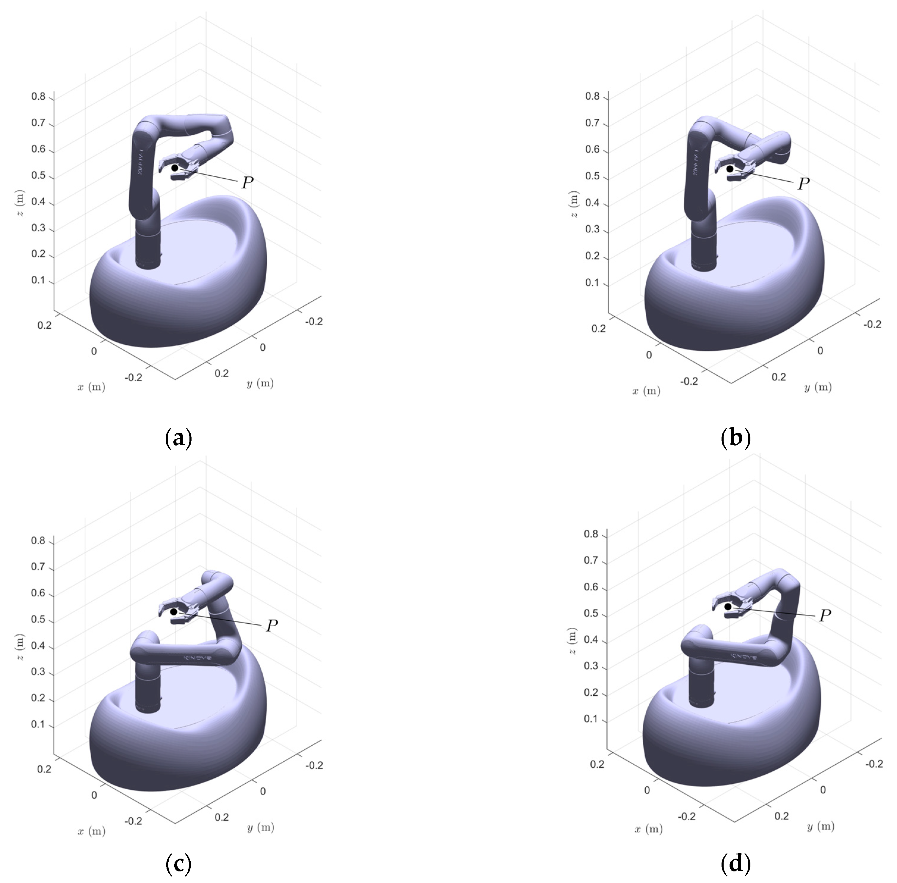
1.2. On the Inverse Kinematics Problem of the Kinova Gen3 Lite

The Kinova Gen3 lite arm is a serial collaborative manipulator with six revolute joints (6R). This category of manipulators has a maximum number of 16 different solutions for a given pose, as demonstrated by Pimrose [18] and Lee et al. [19] and used by Zohour et al. [20] to solve the Inverse Kinematic Problem (IKP) of Kinova Gen3 lite; however, this number can possibly be reduced by the joint mobility constraints. For a complete analysis of the dexterity and force transmission properties of the manipulator, which can drastically change in function of the selected posture, the IKP of the arm was solved, taking care to delete the solutions which were not admitted by the joint mobility constraints. Thus, the widest number of possible solutions for a given target point allowed the authors to select the optimal posture of the manipulator to perform a desired task, as presented in the subsequent sections. In Figure 2, four different kinematics solutions of the robot for the same target point P are reported, where only 2a and 2c are admitted according to the joint limit constraints (Table 1).

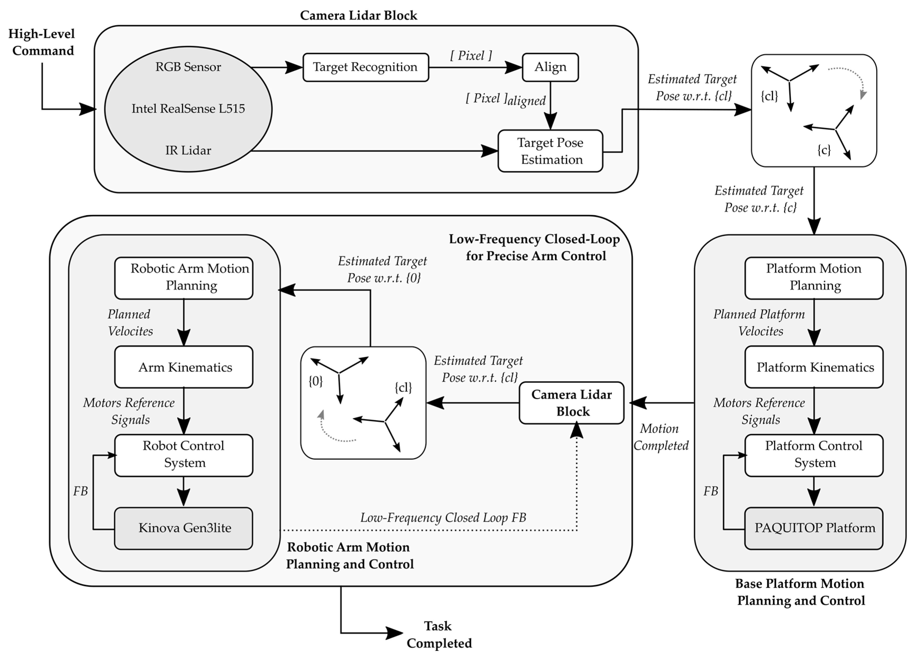
1.3. Camera-Based System Description

To fully perceive and obtain information from the surroundings, exteroceptive systems must be adopted. To provide this information, a LiDAR camera—Intel RealSense L515—was mounted and fixed to the fifth link of the arm, as shown in Figure 3. The camera uses an infra-red (IR) laser beam to scan its entire field of view (FOV), which is reflected and re-captured by an IR photodiode. The data are processed to generate depth cloud points as outputs that represent the entire FOV area, as shown in the figure, where the position of a door handle point with regard to the camera frame is measured. With the use of image recognition techniques, the camera both recognizes the object and calculates an associated reference frame. Once the posture of the robot is known, this information can be converted into the position and orientation of the object with respect to the base frame of the robot, allowing it to reach the object and interact with it.
To better clarify how the system will work in real applications, Figure 4 presents the overall architecture for autonomous task execution. This strategy takes advantage of both the RGB sensor and the IR scanner to recognize the target and its pose with respect to the LiDAR camera { c l } r.f. This information is transposed into the r.f. { c } so that it can be used to move the platform into a position where the robotic arm can better perform the given task. Once the platform motion is completed, a low-frequency closed-loop control is performed to precisely move the robotic arm towards the goal pose. The choice of moving the platform and the robotic arm separately has been adopted to simplify the control strategy at this preliminary stage.

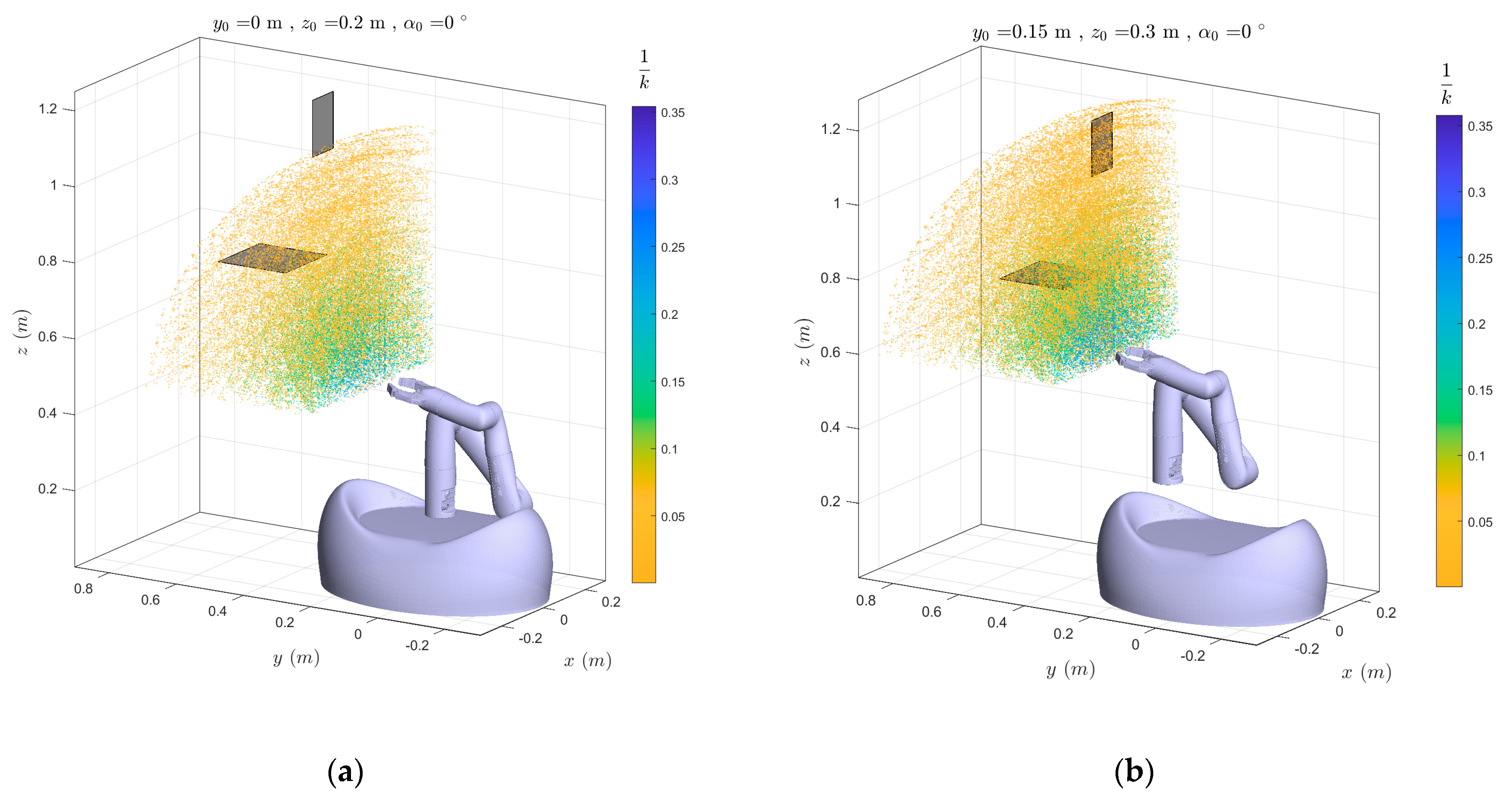
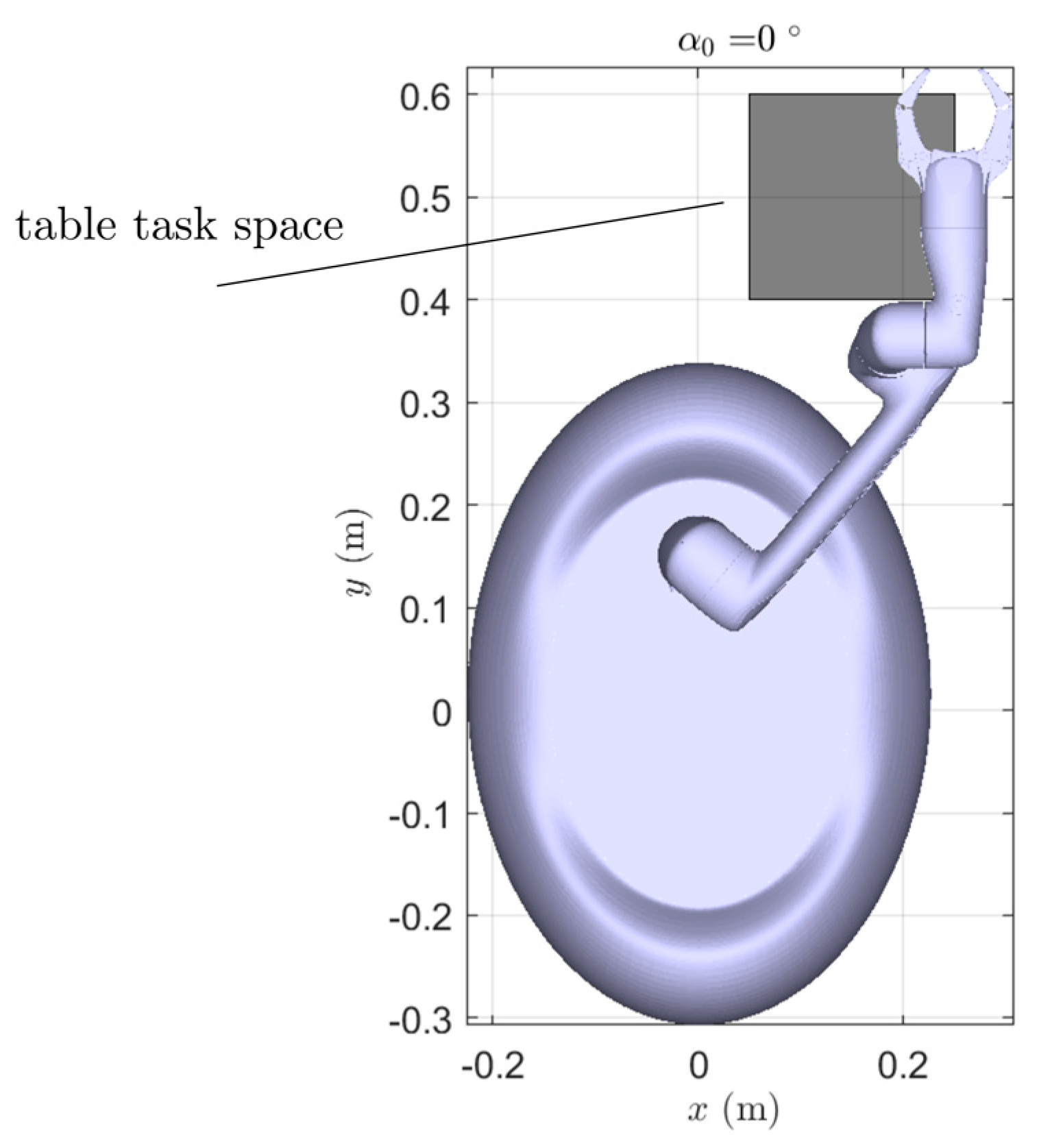
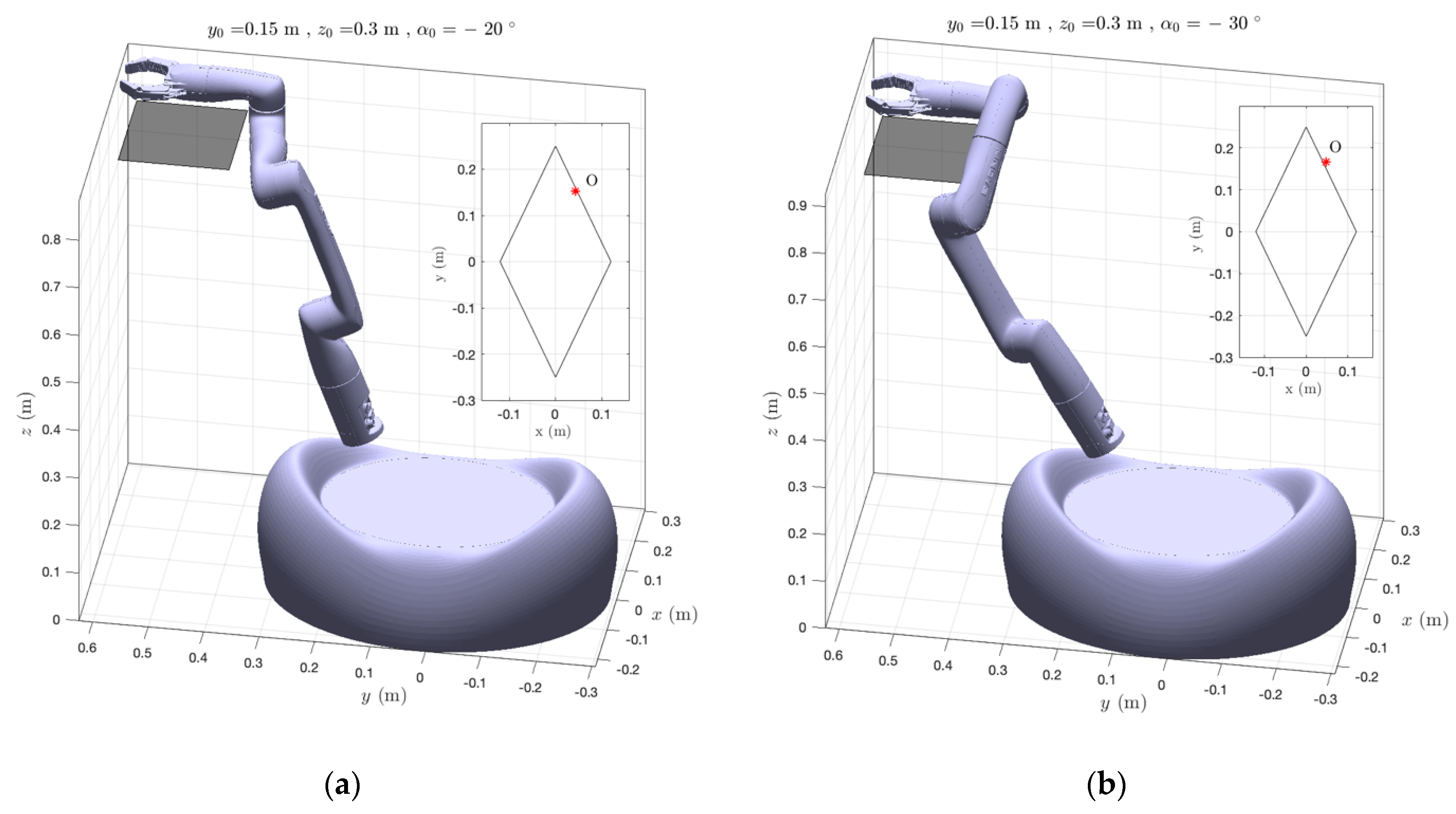
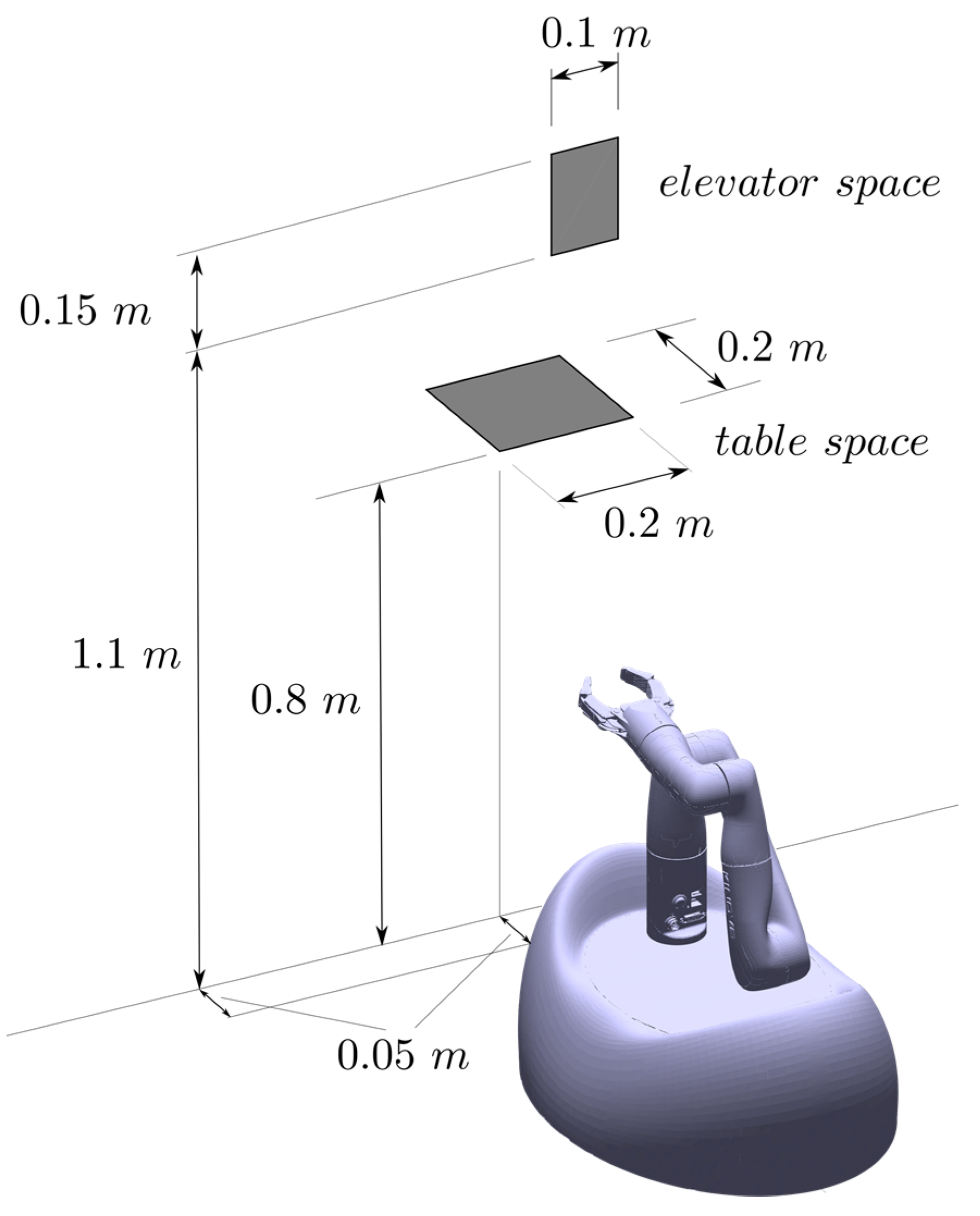
2. Task-Oriented Approach for Analysis of Mounting Parameters

To guide the mounting parameter selection, a task-oriented approach was adopted. Due to the application, the robot should be able to perform pick-and-place operations upon a table (or a generic plane) and to reach and pull objects such as elevator buttons and door handles to enhance its self-navigation capability.
The first task was modeled as a 0.2 m × 0.2 m square at a reasonable height of 0.8 m (Figure 5), which makes this task similar to those of human interactions. For the second task, the manipulator was required to reach and apply small forces in a portion of the vertical plane at a height from 1.1 m to 1.25 m, corresponding to the height of a generic elevator button. Thanks to its omnidirectional properties, the platform can position itself in different relative postures with respect to the task space. In this way, the different portions of the manipulator workspace could be exploited, as discussed below.
For both table and elevator tasks, the platform was supposed to be able to position itself with a minimum distance of 0.05 m between the task and the platform edge. In the figure, the robot arm is represented in a retracting posture, with mounting parameters of y 0 = 0.1 m, z 0 = 0.2 m and α 0 = 0 ° . This configuration of the robot arm kept the center of gravity low, which was beneficial during acceleration phases.

Workspace and Stability Analysis

As introduced in the previous section, the parameters y 0 and z 0 significantly affect the capability of the system to reach and manipulate objects in the desired task spaces. Thus, starting from a centered position with the arm directly placed upon the portal structure, these parameters were changed to fully reach both table and elevator spaces. In Figure 6, the interaction between the robot workspace and selected task spaces as a function of the mounting parameter is presented. For the sake of clarity, the workspace was discretized and reduced to the area of major interest for task performance, and it is reported as a point cloud. Although both y 0 and z 0 had beneficial effects on the robot’s capability to assess the task, their impact on the overall stability of the system was quite different. By keeping the arm with a constant minimum height of 0.2 m and moving it along the y axis of r.f. { c } , any posture of the manipulator produced a similar translation of the center of mass of the robot. This displacement could greatly affect the system’s stability. On the other hand, by keeping the y 0 parameter constant and raising the arm with the z 0 value, the same posture of the robot raised the position of its center of mass along. the z axis of { c } . To increase the free space upon the platform, which was intended to be used for other purposes—e.g., storing and transporting objects—it was decided to use the maximum value admitted for y 0 = 0.15 m, which was limited by the dimension of the mounting structure. Then, to minimize the vertical size of the system, the value of z 0 = 0.3 m was chosen since it represented the minimum value that allowed the desired task space to be reached.

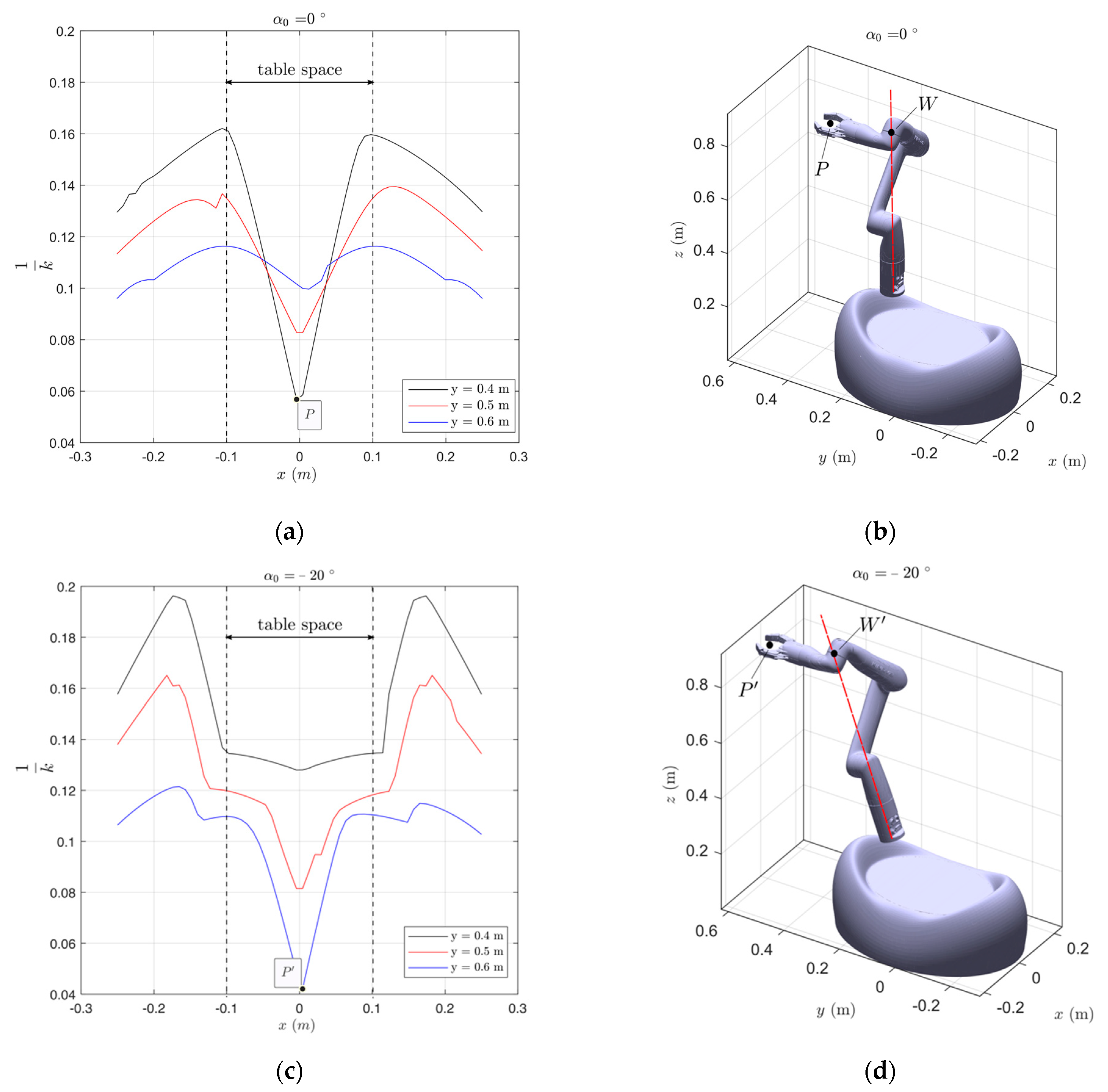
3. Dexterity and Force Transmission Ratio Analysis

Once y 0 and z 0 values were determined, the parameter α 0 and its influence on the task-performing capability of the system were studied. To this purpose, the condition number κ is introduced as
κ = J 1   J
where J = J ( q ) is the Jacobian matrix of the robot arm and q is the joint variables vector. The condition number thus defined is a global parameter that can be used to evaluate the general kinematic behavior of the manipulator, as presented by Merlet in [21]. For this purpose, the two-matrix-norm is used, so that
κ = J 1   J = λ max λ min
where λ max , min are the maximum and minimum eigenvalues of J , respectively, which implies that the κ parameter has values in [ 1 , + ] . To deal with more convenient values, the inverse parameter 1 / κ is used. In this way, the values lie in the range [ 0 , 1 ] , where 0 value represents a singularity condition.
However, since the entries of J matrix have different unit measures, there is a consistency issue that can be solved by dividing the rows associated to the linear twist of the manipulator by a characteristic length L , as introduced and described by Angeles in [22]. Conceptually, the L value for positioning and orienting a manipulator is found to be the length which minimizes the parameter κ ; i.e.,
L : max q , L 1 κ ( J ( q ) )
For the Kinova Gen3 Lite arm, the solution is as follows:
L = 0.178   mm ,   q 1 = 0 ° ,   q 2 = 37.9 ° ,   q 3 = 113.7 ° ,   q 4 = 95.0 ° ,   q 5 = 125.5 ° ,   q 6 = 0.0 ° ( 1 κ ) max = 0.4
where ( 1 / κ ) m a x is the maximum value of 1 / κ that the robot can achieve inside its workspace. It is worth noticing that q 1 does not influence the value of the length L , because it has only the effect of rotating the whole structure along the first joint axis, so it has been neglected for the numerical solution of the problem. Now that J is consistent in unit measures, the κ factor can be properly evaluated. Notice that the choice of y 0 and z 0 values have the beneficial effect of incrementing the 1 / κ value inside the task space, as mentioned above and reported in Figure 5, leading to a better capability of the manipulator to perform the desired task.

3.1. Dexterity Analysis

In Figure 7a,c, the level curves of 1 / κ ( x , y ) are presented for the two different values of inclination α 0 , as shown in Figure 7b,d, respectively. Each curve represents the trend of 1 / κ ( x ) with a constant value of y (thus, for a vertical slice of the robot workspace). As described in Section 1.2, there are multiple solutions for a desired target point P , and each leads to different values of the 1 / κ ratio. From the wide range of possible solutions for a target point P , which in general are equal to 16, the extracted posture was the one with the maximum 1 / κ dexterity index value.
Besides, the study was conducted on a domain characterized by a range on the x axis wider than the range selected for the task. Since the robot was required to exhibit good dexterity to manipulate objects on the table domain, this choice was made to evaluate the best position of the table task space with regard to the fixed r.f. { c } for operating with the highest possible dexterity. From a different—yet equivalent—point of view, the study aimed to find the placement of the mobile platform that enabled the manipulator to operate with the best-allowed dexterity. For the sake of clarity, it is worth pointing out that the same extension cannot be done along the y axis of { c } : higher values of y 0 result in severe balance problems, due to a more extended posture of the manipulator, while with lower values, the platform would come into geometric interference with the table.
To successfully perform the task, it was assumed that the z axis of r.f. { e } was always aligned with the y axis of r.f. { c } , implying the manipulator selected objects with the gripper placed horizontally. Moreover, the { c } r.f. was positioned with a height of 0.05 m upon the table to avoid geometric interference.
Figure 7a,c show the robot arm close to singular postures in P and P . In these configurations, the point W (labeled in Figure 7b,d) almost intersects with the first joint axis, representing a singularity for the serial manipulator. The closeness to this configuration results in very low values of the dexterity parameter 1 / k of 0.057 and 0.042, respectively. Moreover, the diagrams show that a change of the parameter α 0 from 0 ° to 20 ° results in a positive shift along the y axis of the point where the arm was close to singularity. To avoid these issues, the table task space should be positioned with a non-null distance along x , corresponding to a lateral approach of the manipulator to the task, as shown in Figure 8, where the robot posture is represented while reaching out to the extreme point of the task space.
With a lateral approach of the platform and a tilted configuration of the robot arm, the dexterity factor 1 / κ increases. To quantify these beneficial effects and to evaluate a wider set of α 0 , the Global Conditioning Index ( G C I ), as defined by Merlet [21], was evaluated. This parameter is a synthetic dexterity index of the robot, defined by
G C I ( % ) = D 1 κ d D D d D 100
where D is the table task-space domain. The numerically computed results are presented in Table 2, where it is clear that tilting the arm towards the task space is beneficial to increase the global dexterity of the robot inside the table task space.
As shown in Figure 9, where the most critical postures both for geometrical interference and static balance issues are reported, the choice of α 0 = 30 ° leads to geometric interference with the table; therefore, this mounting setup must be rejected. The value α 0 = 20 ° was found to be a feasible trade-off (Figure 9a), and it guarantees the static balance of the system since the projection O (red star point) of its center of mass is inside the support polygon.

3.2. Transmission Ratio Analysis

Aside from good dexterity, the system must generate lifting forces along the z axis of { c } to lift objects from the table. Thus, it is useful to study the force ellipsoid of the manipulator. As described by Chiu in [23], the robot can be described as a mechanical transformer from the joint torque space to forces in task space.
The force ellipsoid is described as
f T ( J J T ) f = 1
where f is the force vector defined in the task space. The generic force transmission ratio α along the direction u ^ must fulfil the condition
( α u ^ ) T ( J J T ) ( α u ^ ) = 1
which allows the force transmission ratio α z along the z axis of { c } to be computed as
( α z z ^ ) T ( J J T ) ( α z z ^ ) = 1
It is worth highlighting that the force ellipsoid strictly depends on the robot’s posture, defined by the vector of joint angles q . Thus, a study was made with the same criteria adopted for dexterity analysis, meaning that the robot adopted the posture with the highest possible dexterity index. The resulting force transmission ratio along the z axis of { c } is reported in terms of level curves in Figure 10, where each curve represents the trend of α z ( x ) at a constant value of y . A global increase of the factor α z occurs if a tilting angle is applied, meaning that with α z = 20 ° , lower joint torques are required for the same applied forces on the end-effector within the selected task space.

4. Conclusions

The paper defines a mounting guideline to install a robotic arm on an omnidirectional mobile platform. This methodology is presented in the specific case of the installation of a Kinova Gen3 Lite on a prototype of the Paquitop platform. Possibly, similar approaches could be used and adapted to other manipulators and platforms. The methodology consists of a task-oriented analysis to study the optimal mounting position and orientation of the robotic manipulator on the mobile platform to properly reach and perform different tasks while preserving the total encumbrance of the prototype. According to this consideration, the robotic arm can be mounted with characteristics of y 0 = 0.15 m and z 0 = 0.3 m.
Based on the dexterity index 1 / κ and the force transmission ratio α z , a tilted configuration of the robot arm towards the table task space ensures a better capability for performing the tasks, even if the geometric interference with the table must be avoided, leading to a trade-off value of 20 ° .
Finally, it is worth remarking that one of the most interesting features of the proposed system is its reduced weight, which makes it particularly feasible for home applications. As a side effect, special attention must be paid to the stability of the whole system, which can be jeopardized under particular motion conditions. In fact, although the stability has been proven in this paper in static conditions, the inertial solicitations derived from poorly planned movements of the arm can affect the equilibrium of the robot. Thus, future investigations must be performed to ensure the dynamic stability of the whole system. Specific planning algorithms must be considered, such as the well-known Zero-Moment-Point, to generate trajectories that do not cause the platform to overturn in any admitted use condition. This point in particular requires a deep experimental investigation, which is the object of on-going research.

Author Contributions

Conceptualization, G.C., L.T., P.C., A.B. and G.Q.; Data curation, G.C. and L.T.; Formal analysis, G.C., L.T. and L.C.; Project administration, G.Q.; Supervision, L.C. and Giuseppe Quaglia; Visualization, Giovanni Colucci and Luigi Tagliavini; Writing—original draft, G.C. and L.T.; Writing—review and editing, L.C., P.C., A.B. and G.Q. All authors have read and agreed to the published version of the manuscript.

Funding

This research received no external funding.

Institutional Review Board Statement

Not applicable.

Informed Consent Statement

Not applicable.

Data Availability Statement

The data presented in this study are available on request form the corresponding author.

Conflicts of Interest

The authors declare no conflict of interest.

References

  1. Romero-Garcés, A.; Martínez-Cruz, J.; Inglés-Romero, J.F.; Vicente-Chicote, C.; Marfil, R.; Bandera, A. Measuring quality of service in a robotized comprehensive geriatric assessment scenario. Appl. Sci. 2020, 10, 6618. [Google Scholar] [CrossRef]
  2. Christoforou, E.G.; Avgousti, S.; Ramdani, N.; Novales, C.; Panayides, A.S. The upcoming role for nursing and assistive robotics: Opportunities and challenges ahead. Front. Digit. Health 2020, 2, 39. [Google Scholar] [CrossRef]
  3. Kyrarini, M.; Lygerakis, F.; Rajavenkatanarayanan, A.; Sevastopoulos, C.; Nambiappan, H.R.; Chaitanya, K.K.; Babu, A.R.; Mathew, J.; Makedon, F. A survey of robots in healthcare. Technologies 2021, 9, 8. [Google Scholar] [CrossRef]
  4. Yang, G.Z.; Nelson, B.J.; Murphy, R.R.; Choset, H.; Christensen, H.; Collins, S.H.; McNutt, M. Combating COVID-19-The role of robotics in managing public health and infectious diseases. Sci. Robot. 2020, 5, eabb5589. [Google Scholar] [CrossRef] [PubMed] [Green Version]
  5. Campion, G.; Bastin, G.; Dandrea-Novel, B. Structural properties and classification of kinematic and dynamic models of wheeled mobile robots. IEEE Trans. Robot. Autom. 1996, 12, 47–62. [Google Scholar] [CrossRef]
  6. Duy, V.H.; Dao, T.T.; Quang, N.T.; Le, N.B. Study on mechanical structure design for innovative multi-function assistive mobile robot. Recent Adv. Electr. Eng. Relat. Sci. 2016, 371, 645–654. [Google Scholar]
  7. Dragoicea, M.; Shivarov, N. Assistive mobile robot technology for real-time task implementation. In Proceedings of the RAAD, 18th International Workshop on Robotics in Alpe-Adria-Danube Region, Brasov, Romania, 25–27 May 2009; Volume 4. [Google Scholar]
  8. Canal, G.; Escalera, S.; Angulo, C. A real-time human-robot interaction system based on gestures for assistive scenarios. Comput. Vis. Image Understand. 2016, 149, 65–77. [Google Scholar] [CrossRef] [Green Version]
  9. Chwa, D. Tracking control of differential-drive wheeled mobile robots using a backstepping-like feed-back linearization. IEEE Trans. Syst. Man Cybern. Syst. 2010, 40, 1285–1295. [Google Scholar] [CrossRef]
  10. Yunardi, R.T.; Arifianto, D.; Bachtiar, F.; Prananingrum, J.I. Holonomic implementation of three wheels omnidirectional mobile robot using dc motors. J. Robot. Control 2021, 2, 65–71. [Google Scholar] [CrossRef]
  11. Carbonari, L.; Botta, A.; Cavallone, P.; Quaglia, G. Functional design of a novel over-actuated mobile robotic platform for assistive tasks. In Proceedings of the International Conference on Robotics in Alpe-Adria Danube Region, Poitiers, France, 17–19 June 2020; Springer: Cham, Switzerland, 2020; pp. 380–389. [Google Scholar]
  12. Tagliavini, L.; Botta, A.; Carbonari, L.; Quaglia, G.; Gandini, D.; Chiaberge, M. Mechatronic design of a mobile robot for personal assistance. In Proceedings of the ASME 2021 International Design Engineering Technical Conferences & Computers and Information in Engineering Conference, Online, 17–19 August 2021. [Google Scholar]
  13. Tagliavini, L.; Botta, A.; Cavallone, P.; Carbonari, L.; Quaglia, G. On the suspension design of paquitop, a novel service robot for home assistance applications. Machines 2021, 9, 52. [Google Scholar] [CrossRef]
  14. Carbonari, L.; Botta, A.; Cavallone, P.; Tagliavini, L.; Quaglia, G. Dynamics Characterization of Paquitop: A Novel Platform for Robotized Domestic Applications. In Proceedings of the ASME 2020 International Mechanical Engineering Congress and Exposition, Dynamics, Vibration, and Control, Virtual (Online), 16–19 November 2020; Volume 7B. [Google Scholar]
  15. Carbonari, L.; Tagliavini, L.; Botta, A.; Cavallone, P.; Quaglia, G. Preliminary observations for functional design of a mobile robotic manipulator. Mech. Mach. Sci. 2021, 102, 39–46. [Google Scholar]
  16. Bostelman, R.; Hong, T.; Marvel, J. Performance measurement of mobile manipulators. In Multisensor, Multisource Information Fusion: Architectures, Algorithms, and Applications; International Society for Optics and Photonics: Bellingham, WA, USA, 2015; Volume 9498. [Google Scholar]
  17. El Dine, K.M.; Corrales Ramon, J.A.; Mezouar, Y.; Fauroux, J.C.A. Unified Mobile Manipulator Control for On-line Tip-over Avoidance Based on ZMP Disturbance Observer. In Proceedings of the IEEE International Conference on Robotics and Biomimetics (ROBIO), Kuala Lumpur, Malaysia, 12–15 December 2018; pp. 1437–1443. [Google Scholar]
  18. Primrose, E.J. On the input-output equation of the general 7R mechanism. Mech. Mach. Theory 1986, 21, 509–510. [Google Scholar] [CrossRef]
  19. Lee, H.Y.; Woernle, C.; Hiller, M. A complete solution for the inverse kinematic problem of the general 6r robot manipulator. J. Mech. Des. 1991, 113, 481–486. [Google Scholar] [CrossRef]
  20. Zohour, H.; Belzile, B.; St-Onge, D. Kinova Gen3-Lite manipulator inverse kinematics: Optimal polynomial solution. arXiv 2021, arXiv:2102.01217. [Google Scholar]
  21. Merlet, J.P. Jacobian, manipulability, condition number, and accuracy of parallel robots. J. Mech. Des. 2006, 128, 199–206. [Google Scholar] [CrossRef]
  22. Angeles, J. Fundamentals of Robotic Mechanical Systems, Theory, Methods and Algorithms, 2nd ed.; Springer: New York, NY, USA, 2003; pp. 180–188. [Google Scholar]
  23. Chiu, S.L. Task compatibility of manipulator postures. Int. J. Robot. Res. 1988, 7, 13–21. [Google Scholar] [CrossRef]
Figure 1. (a) The updated Paquitop mobile platform with the mounting structure. The two steering wheels are positioned along the major axis of the elliptical footprint, and the passive castor wheels are positioned along the minor axis. Thus, the resulting support polygon has a rhombic shape. (b) Paquitop.arm system and reference frame definition. Notice that { c } is fixed to the mobile platform, positioned at ground level and in the center of the elliptical footprint. { c l } is the r.f. of a LiDAR camera, which is presented and discussed below.
Robotics 10 00102 g001
Figure 2. Example of four kinematics solutions to reach the target point P = ( 0.15 , 0.25 , 0.55 ) m. While (a) is quite similar to (b,c) is similar to (d), only (a,c) are admitted due to the joint limit constraints.
Robotics 10 00102 g002
Figure 3. Paquitop.arm prototype with the Intel L515. On the right of the figure, the camera depth view is shown, with the distance measurement of a door handle point.
Robotics 10 00102 g003
Figure 4. Overall architecture for autonomous task execution.
Robotics 10 00102 g004
Figure 5. Task space representation with the arm in the retracted posture. The platform was supposed to reach the desired task space with a minimum y distance of 0.05   m between the task and the platform edge. The mounting parameters were y 0 = 0.1 m, z 0 = 0.2 m, α 0 = 0 ° .
Robotics 10 00102 g005
Figure 6. Influence of y 0 and z 0 on the relative position between the robot workspace (colored points cloud) and desired task spaces (gray rectangles): (a) with y 0 = 0   m , z 0 = 0.2   m , α 0 = 0 ° , the elevator space was not reached; (b) with y 0 = 0.15   m , z 0 = 0.3   m , α 0 = 0 ° , the elevator space was fully reached and the value of the 1 / k parameter inside the table space increased.
Robotics 10 00102 g006
Figure 7. (a) Level curves of 1 / k ( x , y ) with respect to r.f. { c } , with α 0 = 0 ° . The domain is a X Y plane in order to evaluate the best position of the platform to approach the task. (b) Posture of the robot with { e } r.f. positioned at P = ( 0 ,   0.4 ,   0.85 ) m. (c) Level curves of 1 / k ( x , y ) with respect to r.f. { c } , with α 0 = 20 ° . (d) Posture of the robot with { e } r.f. positioned at P = ( 0 ,   0.6 ,   0.85 ) m.
Robotics 10 00102 g007
Figure 8. The lateral approach of the mobile platform to the table task space, represented with a gray rectangle. The posture of the robot is computed to reach the extreme point of the space.
Robotics 10 00102 g008
Figure 9. (a) Choice of α 0 = 20 ° . No geometric interferences with the table are noticed, and the projection O of the center of mass of the system is inside the support polygon of the structure. (b) Interference between the arm and the table with the choice of α 0 = 30 ° . O is slightly outside the support polygon, so static balance is not guaranteed.
Robotics 10 00102 g009
Figure 10. Level curves of force transmission ratio α z ( x , y ) for two values of the mounting parameter α 0 . The forward orientation of the manipulator towards the table task space has the global beneficial effect of increasing the value of the α 0 ratio.
Robotics 10 00102 g010
Table 1. Joint angles for the four solutions of Figure 2. The angles that are not admitted are highlighted with gray color.
JointInverse Kinematics Solutions
q ( a ) ( b ) ( c ) ( d )
q 1 112.6 ° 111.5 ° 116.3 ° 107.3 °
q 2 2.8 ° 2.8 ° 78.3 ° 78.5 °
q 3 68.1 ° 94.1 ° 93.0 ° 68.3 °
q 4 7.8 ° 177.3 ° 25.6 ° 162.9 °
q 5 111.3 ° 111.4 ° 83.5 ° 93.0 °
q 6 20.6 ° 172.6 ° 103.2 ° 99.7 °
Table 2. Computed G C I   ( % ) index on the table space area as a function of α 0 .
α 0 G C I ( % )
0 ° 12.9 %
10 ° 13.0 %
20 ° 13.7 %
30 ° 14.4 %
Publisher’s Note: MDPI stays neutral with regard to jurisdictional claims in published maps and institutional affiliations.

