Article

Mechanical Behaviour of Large Strain Capacitive Sensor with Barium Titanate Ecoflex Composite Used to Detect Human Motion

1
Department of Mechanical Engineering, University of Auckland, Auckland 1010, New Zealand
2
Department of Engineering Science, University of Auckland, Auckland 1010, New Zealand
3
Department of Mechanical Engineering, University of Bath, Bath BA2 7AY, UK
*
Author to whom correspondence should be addressed.
Robotics 2021, 10(2), 69; https://doi.org/10.3390/robotics10020069
Submission received: 24 March 2021 / Revised: 29 April 2021 / Accepted: 30 April 2021 / Published: 4 May 2021
(This article belongs to the Section Sensors and Control in Robotics)

Abstract

:
In this paper, the effect of strain rate on the output signal of highly stretchable interdigitated capacitive (IDC) strain sensors is studied. IDC sensors fabricated with pristine Ecoflex and a composite based on 40 wt% of 200 nm barium titanate (BTO) dispersed in a silicone elastomer (Ecoflex 00-30TM) were subjected to 1000 stretch and relax cycles to study the effect of dynamic loading conditions on the output signal of the IDC sensor. It was observed that the strain rate has no effect on the output signal of IDC sensor. To study the non-linear elastic behaviour of pristine Ecoflex and composites based on 10, 20, 30, 40 wt% of 200 nm BTO filler dispersed in a silicone elastomer, we conducted uniaxial tensile testing to failure at strain rates of ~5, ~50, and ~500 mm/min. An Ogden second-order model was used to fit the uniaxial tensile test data to understand the non-linearity in the stress-strain responses of BTO-Ecoflex composite at different strain rates. The decrease in Ogden parameters (α1 and α2) indicates the decrease in non-linearity of the stress-strain response of the composite with an increase in filler loading. Scanning electronic microscopy analysis was performed on the cryo-fractured pristine Ecoflex and 10, 20, 30, and 40 wt% of BTO-Ecoflex composites, where it was found that 200 nm BTO is more uniformly distributed in Ecoflex at a higher filler loading levels (40 wt% 200 nm BTO). Therefore, an IDC sensor was fabricated based on a 40 wt% 200 nm BTO-Ecoflex composite and mounted on an elastic elbow sleeve with supporting electronics, and successfully functioned as a reliable and robust flexible sensor, demonstrating an application to measure the bending angle of an elbow at slow and fast movement of the arm. A linear relationship with respect to the elbow bending angle was observed between the IDC sensor output signal under a 50% strain and the deflection of the elbow of hand indicating its potential as a stretchable, flexible, and wearable sensor.

1. Introduction

Strain sensors (strain gauges) are widely used mechanical sensors, to measure mechanical deformation by transducing the mechanical stimulus to an electrical signal [1]. The need for stretchable, flexible, and wearable sensors has led to conventional brittle strain sensors being replaced by soft, stretchable, and robust strain sensors. Recently, stretchable and wearable strain sensors have shown potential for a broad range of applications for structural health monitoring of conformal surfaces such as parachutes [2], human motion detection [3], healthcare monitoring [4], smart skins [5], tire strain monitoring for intelligent tires [6], and soft robotics [7,8]. The desirable characteristics of an efficient stretchable strain sensor are high stretchability (ε ≥ 100%, where ε is strain), lightweight, a high degree to repeatability (~1000 cycles of testing), durability, robustness (consistent output signal over a period of time) [9], and biocompatibility, in particular for strain sensors in biomedical applications [4]. Stretchable strain sensors are likely to be subjected to a dynamic strain when used in real time applications, as the movement’s speed of an elbow, hand [10], knee [11,12], robotic arm, etc. varies with time. Therefore, it is important to study the strain rate dependent behaviour of the output signal of strain sensors to provide a consistent response, in order to achieve a stable and reliable strain sensor.
Transducing the mechanical stimulus into an electrical signal is undertaken by several sensing mechanisms such as resistance, capacitance, and piezoelectric effects. While the most widely used strain sensing mechanism is based on resistance, capacitive strain sensors have several advantages over both resistance and piezoelectric based strain sensors. These include a lower hysteresis [13], faster response time [14], higher degree of linearity [15], a higher tolerance to overpressure conditions sustained in harsh environments [14], and an ability to operate over wide temperatures with a lower sensitivity to temperature and noise [2]. Capacitive strain sensors are formed from various rigid materials such as indium tin oxide (ITO) for a 90% transparent capacitive sensor for mobile touch screens [16], and ceramics such as barium titanate (BaTiO3, BTO) with a high relative permittivity (εr) [17,18,19], where εr ~1500–15000, and varies based on the particle size. Ceramic based sensors also have a limitation of stretchability and cannot be used to measure the strain of conformal surfaces such as electronic skins and soft robotics.
In order to overcome these limitations, stretchable strain sensors can be fabricated using polymers such as silicone-based elastomers (EcoflexTM), blended with a high permittivity ceramic (such as BTO) to increase the elastomer’s permittivity and still has high stretchability. The balance of the elastic properties and dielectric constant of the ceramic-elastomer composite have to be considered in detail to realize a highly stretchable capacitive strain sensor with the appropriate combination of mechanical and dielectric properties [1,20,21]. A further advantage of using a particle filled elastomer composite is that the fabrication of strain sensors can be undertaken at room temperature, unlike the high temperatures required to process ceramics.
Capacitance-based stretchable strain sensors are often available in two types, the first is a parallel plate capacitive strain sensor which is constructed by overlapping several layers of conductive/dielectric polymers. The second type is an interdigitated electrodes based capacitive strain sensor which typically consists of a sandwich of the interdigitated electrodes structure between the two dielectric layers. The stretchable parallel layered capacitive strain sensor has limitations such as a limit in the strain measurement due to the small vertical distance between the parallel layers of polymers at high strain. As a result, interdigitated capacitive (IDC) strain sensors are of interest when operating at high strains and are easy to customize for a range of biomedical and robotic applications [14].
The interdigitated electrode structure was initially reported by N. Tesla in his patent issued in 1891 [22]. The gradual transition from a parallel plate capacitor to a planar capacitor is presented in Figure 1f. The capacitance between the coplanar interdigitated electrodes was calculated in the early 1920s [23]. The widespread use of the IDC electrodes for sensing applications commenced in the 1960s [24,25]. The literature from the last two decades shows that interdigitated capacitive (IDC) sensors exhibit a limited strain. For example, IDC sensors fabricated using a natural rubber base material using photolithography to create the IDC electrodes structure with a gold material exhibited a 10% strain [6]. An IDC sensor formed using an etherester amide (EEA) elastomer polymer substrate with silver electrodes was fabricated using a direct write thermal spray technology and reported a 0.18% strain [26]. For an IDC sensor fabricated with a polyimide substrate with nickel-gold electrodes formed using a thin-film technology, a 2% strain was reported [27]. An IDC sensor constructed with a polydimethylsiloxane (PDMS) substrate using three-dimensional printing to create the IDC electrodes using a CNT/PDMS conductive ink exhibited a 50% strain [28]. IDC sensors fabricated from the silicone-based elastomer (Ecoflex 00-50TM) consisting of an IDC electrode structure using a silver/PVA conductive ink with laser trenching technique showed a 63% strain [29]. A recent [2] method to create an IDC electrode structure by aerosol jet printing on a polymethyl methacrylate (PMMA) substrate material led to a strain of only 10% [2]. In this paper, we therefore present our study on the effect of strain rate on the output signal of highly stretchable IDC strain sensor fabricated with the BTO-Ecoflex composite substrate subjected to a much higher strain, i.e., up to 100%.
The BTO-Ecoflex composite can be regarded as a viscoelastic material. Therefore, uniaxial tension testing was conducted on the BTO-Ecoflex composite substrate materials to study the variation of the mechanical properties of the BTO-Ecoflex composite, such as ultimate tensile strength and tensile strain at break at different strain rates.
Several researchers have studied the strain rate dependent viscoelastic properties of elastomers and particle-filled elastomeric composites. For example, Steck et al. studied the non-linear elastic response of a Ecoflex silicone rubber under several uniaxial loading conditions using neo-Hookean, Ogden, Mooney-Rivlin, and Yeoh models, and found that the Ogden hyperelastic model is the most suitable model to describe the uniaxial response of Ecoflex [30]. Kim et al. studied the hyperelastic nature of chloroprene rubber (generally known as Neoprene), and the results show that the Mooney-Rivlin and Neo-Hookean models have limitations to model the large deformations of chloroprene rubber. Therefore, a third order Ogden model was used for numerical analysis of deformation ranges of chloroprene rubber [31]. Yunchoi et al. fabricated an ionic stretchable liquid-based strain sensor for human motion monitoring using a Ecoflex 00-50 silicone based elastomer, and they studied the non-linear elastic behaviour of the elastomeric channel using a fourth order Ogden model [32]. Tobajas et al. studied the non-linear stress-strain behaviour of a Santoprene 101-73 material (used in the automotive and aeronautic sectors) by employing the Ogden model [33]. The study of Dupuis et al. showed that Ogden’s model agrees well with uniaxial compression/decompression tests on polyurethane foam at three different strain rates which shows a non-linear hyperelastic behaviour and a viscoelastic behaviour during large deformation [34]. Bai et al. studied the non-linear viscoelastic behaviour at different strain rates of polyurea under a uniaxial compressive load and found that the Ogden model is the most appropriate model to describe the viscoelastic behaviour at higher strains [35]. In the work presented here, ABAQUS and the ‘cftool’ feature in MATLAB were used to fit experimental uniaxial tensile test data of pristine Ecoflex and BTO-Ecoflex composites, to explore if the Ogden model is the most suitable model to study the strain rate dependent stress-strain behaviour of BTO-Ecoflex composite of the IDC sensors. We have also used scanning electron microscopy to understand the distribution of the BTO filler in the Ecoflex matrix and its potential influence on mechanical properties.

2. Materials and Methods

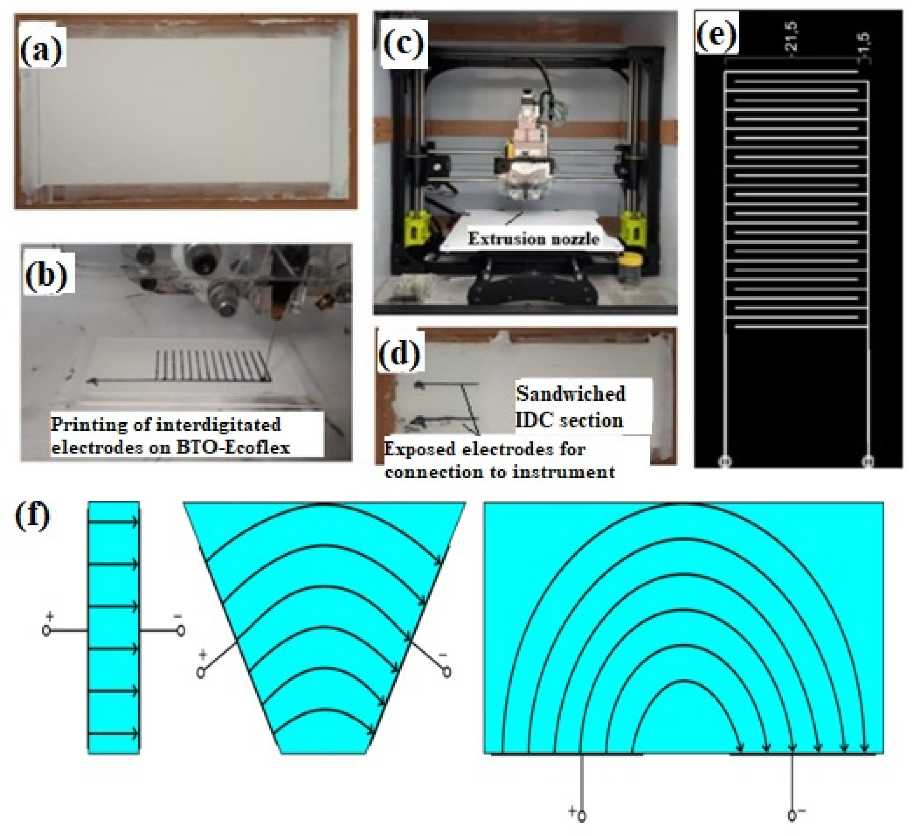
2.1. Fabrication of IDC Sensor

The highly stretchable IDC strain sensor is fabricated with a 40 wt% barium titanate (BTO)-silicone based elastomer (Ecoflex 00-30TM) composite [1], as seen in Figure 1a. The reason for selecting a 40 wt% BTO filler is to create a high relative permittivity substrate material for the IDC sensor, in order to achieve a high initial capacitance and reduce the effect of parasitic capacitance towards the measured capacitance. A further increase in filler loading above 40 wt% leads to failure of the substrate material when subjected to dynamic stretch/relax cycles due to agglomeration of the ceramic filler particles. The IDC electrode structure is shown in Figure 1b and is constructed with carbon black/Ecoflex conductive ink using a customized Lulzbot® 3D printer (Figure 1c) and exposing the electrodes to connect with the testing instrument (see Figure 1d). The design of the IDC electrode structure is presented in Figure 1e. The gradual transition from a parallel plate capacitor to a planar capacitor is presented in Figure 1f. The preparation of the carbon black/Ecoflex 00-30 ink and nomenclature of the IDC electrode structure is presented in the Supplementary Document.

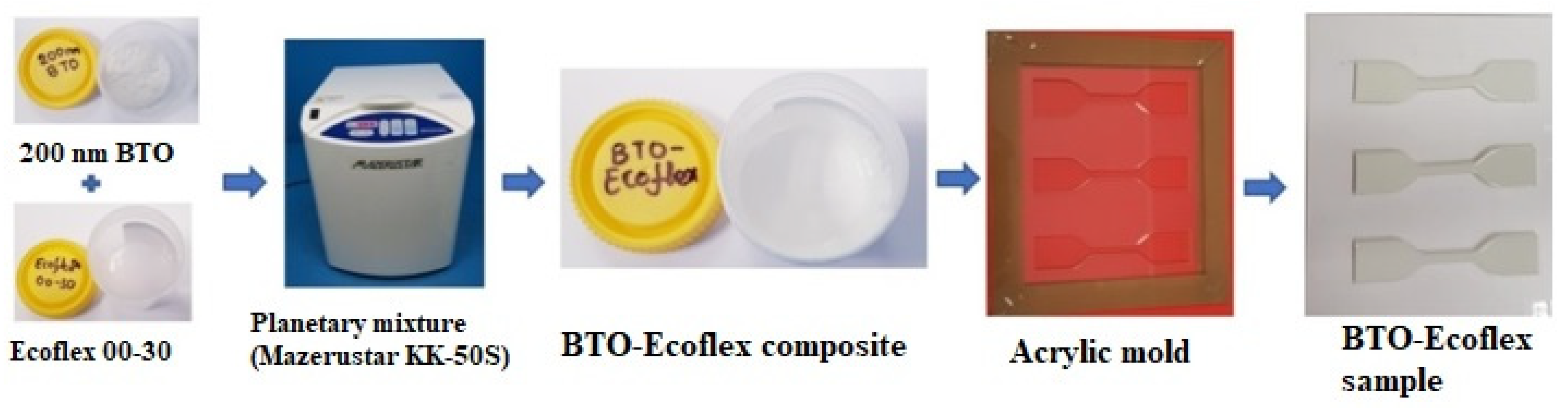
2.2. Fabrication of Composites for Uniaxial Tensile Testing

Tensile test samples were prepared using EcoflexTM 00-30 purchased from Smooth-On (USA), and BTO powder with a particle size of 200 nm, selected due to its high relative permittivity, εr ~5000 [18], from TPL Inc (Albuquerque, NM, USA). Three samples for each composition were prepared for testing, namely 0 (pristine Ecoflex), 10, 20, 30, and 40 wt% of 200 nm BTO. The tensile test samples were prepared by homogeneously mixing the BTO filler powder of the desired wt% in the Ecoflex using a planetary mixture (Mazerustar KK-50S). The mixture was cast using a dog-bone shaped acrylic mold with sample dimensions as per ASTM D412-type C, and left to cure at room temperature for a minimum of 12 h. The dog-bone shaped specimens were extracted from the mold and the overall sample preparation process is illustrated in Figure 2.

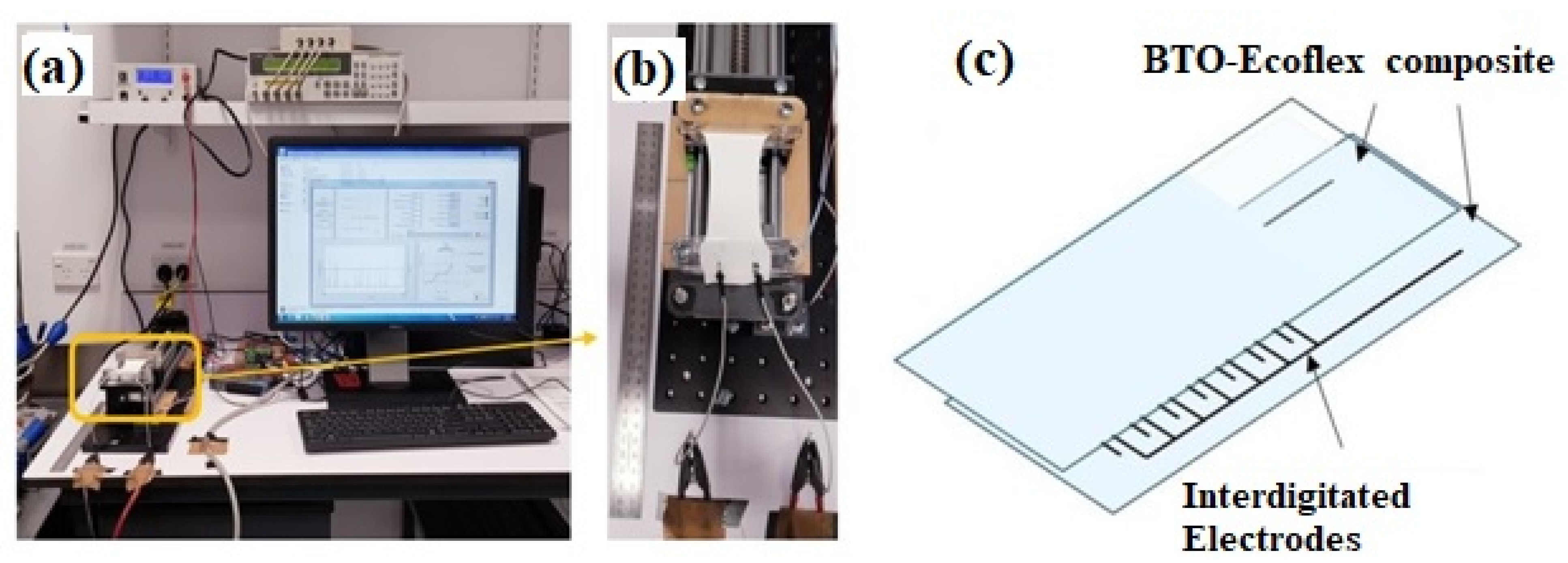
2.3. Stretch-Relax Cyclic Testing of IDC Sensor

In this work, we studied the IDC sensor response at dynamic loading conditions, by conducting 1000 stretch/relax cyclic tests at different strain rates (48 (~50) mm/min and 480 (~500) mm/min), and during each cycle the IDC sensor was subjected to a 100% strain. The cyclic testing was undertaken using an in-house designed and assembled motorized moving stage testing rig. The sensor capacitance was measured at 10 kHz using an Agilent 4263B LCR meter, as presented in Figure 3.

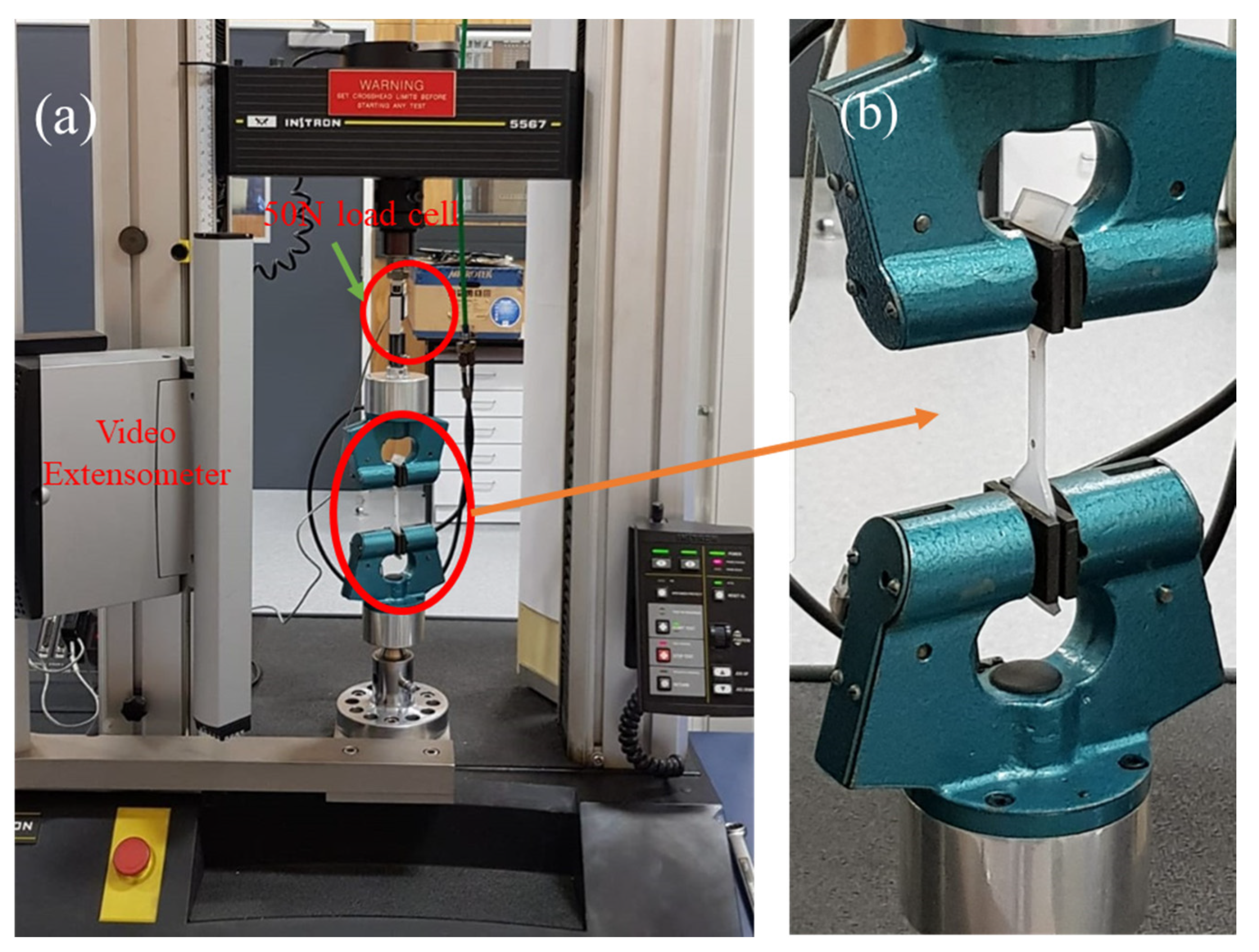
2.4. Uniaxial Tensile Testing at Different Strain Rates of BTO-Ecoflex Composite

The uniaxial tensile test is the most commonly used test to study the strain rate dependent non-linear stress-strain behaviour of viscoelastic composite materials. In this study, the uniaxial tests were carried out to failure of the material, and tests were performed using the Instron 5567 testing machine equipped with a 50 N load cell. The samples were prepared as per ASTM D412-type C, and marked with reference markers at 25 mm spacing to measure the sample displacement using a video extensometer (see Figure 4a), and fixed with two grips as shown in Figure 4b. The thickness and width of the sample, and strain rate are provided in the Bluehill universal dashboard software. The uniaxial tensile tests were performed at three different crosshead speeds: ~5, ~50, and ~500 mm/min. Here, we have included the 5 mm/min strain rate as the mechanical properties of elastomer composites vary at slow quasi-static strain rates [36]. However, in real life applications the IDC sensors are used to measure the strain at higher strain rates. Therefore, we did not include the 5 mm/min (quasi static) strain rate in cyclic testing of the IDC sensor. In the uniaxial tensile test, the stress-strain data are obtained using a 50 N load cell connected to the moving head of the Instron 5567 testing machine. All of the experiments were conducted at room temperature (~25 °C).

3. Results and Discussion

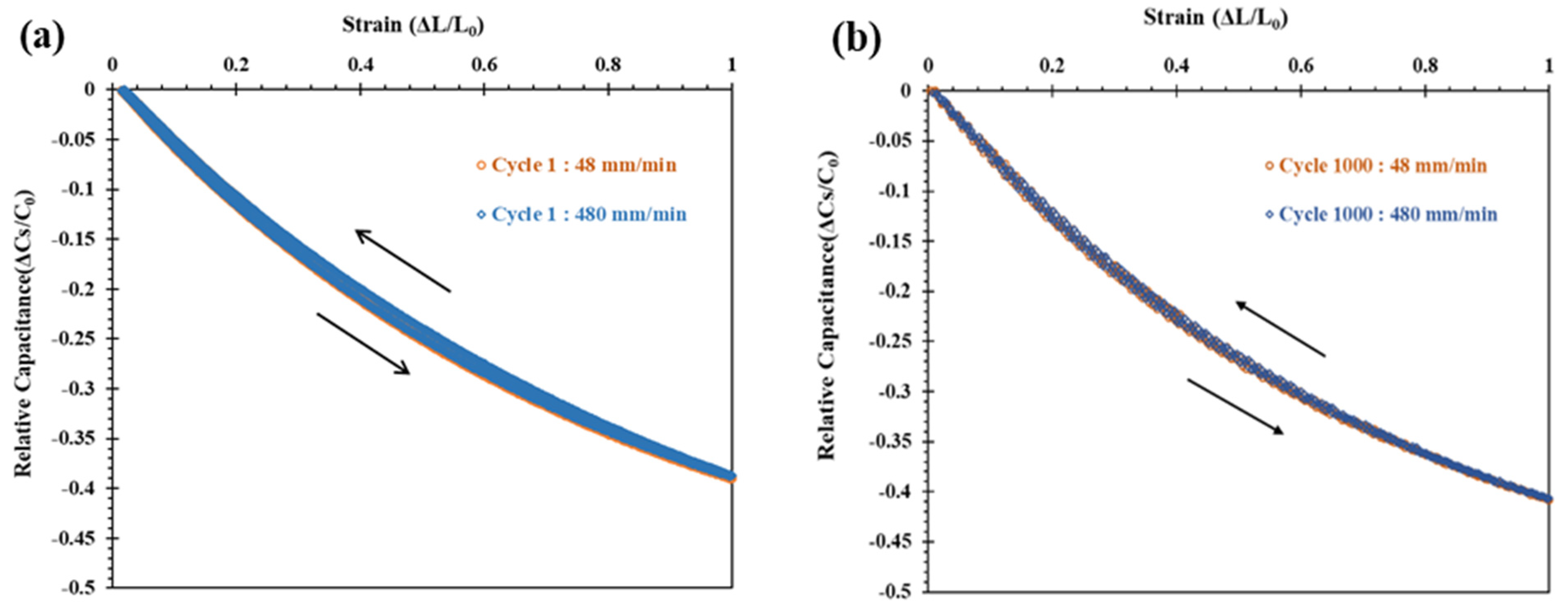
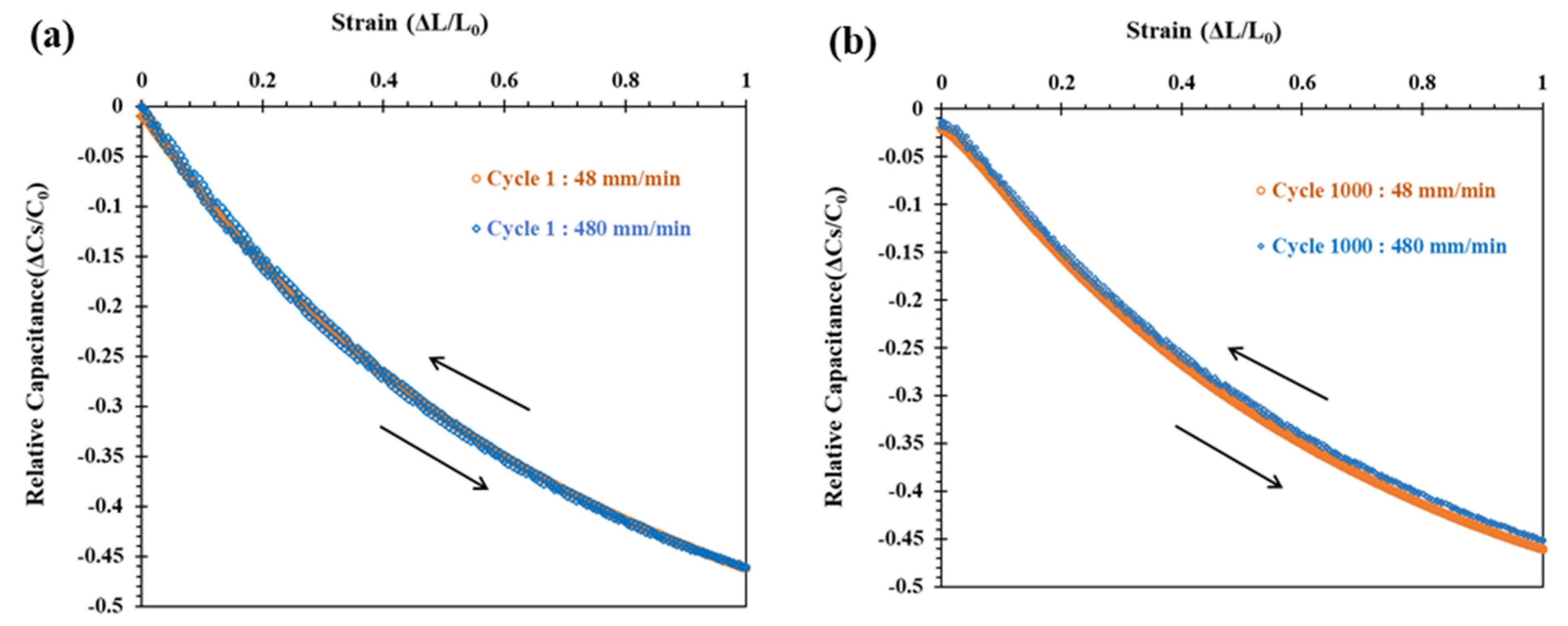
3.1. Strain Rate Dependent Behaviour of IDC Sensor

In the literature, which is also supported with a supplementary document ST.1, most of the work to date did not report the influence of the mechanical properties of IDC sensor substrate materials on the output signal of the IDC sensor when subjected to a variety of static and dynamic loading conditions at a range of strain rates. The output signal of the IDC sensor fabricated with a particulate elastomer composite (BTO-Ecoflex) is likely to be affected by the viscoelastic properties of the composite substrate during static loading conditions. Our recent study on creep testing of IDC sensors (where the strain varies with time at a constant load) showed that the IDC sensor output signal is dependent on the creep behavior due to the viscoelastic nature of the substrate material and, as a result, the distance between the interdigitated electrodes increases as the strain increases at a constant load [37]. However, a stress relaxation study (where the strain is constant while stress varies with time) showed that the IDC sensor output signal is not significantly affected by stress relaxation of the sensor substrate material. This is due to the fact that at a constant strain, the distance between the interdigitated electrodes remains almost constant even though the stress in the substrate material decreases during stress relaxation of the substrate material [38].
In this paper, we examined the output signal of the IDC sensor at dynamic loading conditions with a range of strain rates through cyclic testing of the IDC sensor with two different substrates, including pristine Ecoflex and a 40 wt% 200 nm BTO powder, dispersed in Ecoflex substrate. A low and high speed strain rate were used, namely ~50 and ~500 mm/min, respectively to study the strain rate effect on the sensor output (see Figure 3b). Figure 5 and Figure 6 show the results for the relative change in capacitance against the strain for sensors tested up to 1000 stretch/relax cycles. Figure 5 shows that the IDC sensor fabricated with the pristine Ecoflex substrate shows negligible hysteresis with consistent relative change in capacitance up to a 100% strain at strain rates of ~50 and ~500 mm/min. While the addition of 40 wt% 200 nm BTO filler into Ecoflex increases the viscosity of the composite considerably [37,38], this was shown to have a negligible effect on the output signal of the IDC sensor, with the resulting BTO-Ecoflex composite showing negligible hysteresis with a consistent relative change in capacitance up to a 100% strain at ~50 and ~500 mm/min (see Figure 6).
In summary, the IDC sensors fabricated with pristine Ecoflex and a 40 wt% 200 nm BTO-Ecoflex substrate show a negligible effect of strain rate on the output signal of IDC sensor. While there is some agglomeration and sedimentation of the 200 nm BTO filler in the Ecoflex at this relatively high filler loading level, which will be discussed in detail in the electron microscopy analysis in Section 3.3, this does not affect the performance of the IDC sensor. From Figure 5 and Figure 6, we can conclude that the output signal of the manufactured IDC sensor with a 40 wt% 200 nm BTO-Ecoflex substrate is largely strain rate independent.

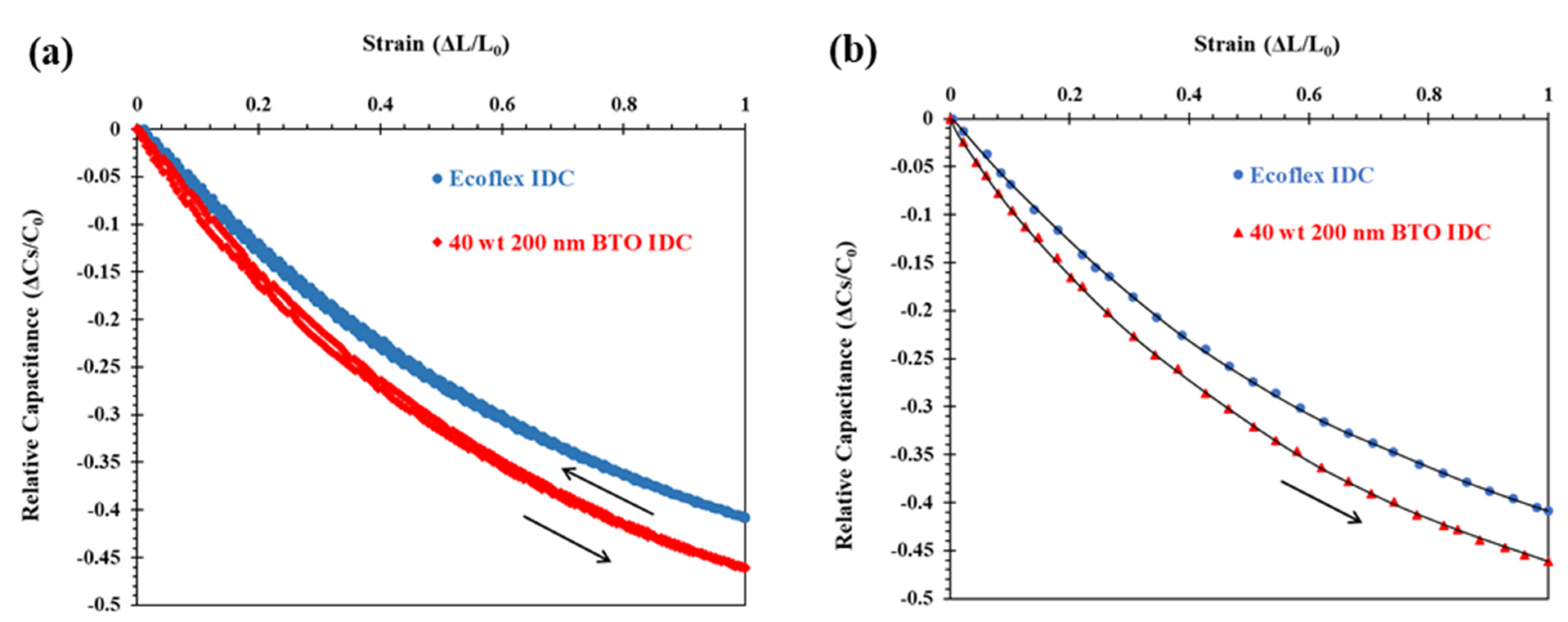
3.2. Sensitivity of Highly Stretchable IDC Sensor to Strain Expressed as Gauge Factor (GF)

The capacitance of a single pair of coplanar interdigitated electrodes can be calculated using the conformal mapping technique, as given by Equation (1) [38,39].
C p = Q 2 V 0 = 2 ε r ε 0 l π ln [ ( 1 + w a ) + ( 1 + w a ) 2 1 ]
where Cp is the capacitance, ε r is the dielectric constant (relative permittivity) of the substrate material, ε 0 is the vacuum permittivity, l is the length of the electrode, w is the width of the electrode, and a is the half-gap between the electrodes.
The relative permittivity of the composite substrate, ε c o m p o s i t e , is calculated using the Lichtenecker model Equation (2) [40], where ε 1 is the relative permittivity of the EcoflexTM 00-30 elastomer ( ε 1 = 2.8 [1,41]) and ε 2 is the relative permittivity of the BTO filler, (for 200 nm BTO, ε 2 = 5000 [17]), and q is the volume fraction of BTO.
l o g   ε c o m p o s i t e = l o g   ε 1 + q   l o g   ( ε 2 ε 1 )
Table S2 in the supplementary information for the 40 wt% 200 nm BTO-Ecoflex composite substrate is ε 40   w t %   200   nm = 5.98 [21].
The total capacitance at a zero strain of interdigitated capacitive strain sensor is calculated using Equation (3) [38,39].
C s = ( 2 N 1 ) C p
where Cs is the capacitance of the IDC sensor at a 0% strain and N is the total number of coplanar electrode pairs.
The relative change in capacitance of the IDC sensor, Equation (4), is independent of the interdigitated transducer dimensions (spacing, length, the thickness of interdigitated electrodes), and is dependent only on the strain (ε), as given by Equation (5) [2,42].
Δ C s C 0 = C C 0 C 0 = C C 0 1
Δ C s C 0 = ( 1 ν ε ) . ( 1 ν ε ) ( 1 + ε ) 1
The gauge factor (GF) represents the sensitivity of the strain sensors. The GF can be defined as the ratio of the relative change of capacitance of the IDC sensor to the corresponding strain. The GF can be calculated by the slope of the relative change of capacitance upon stretching the IDC sensor [42].
G F = Δ C s / C 0 ε = 1 ε [ ( 1 ν ε ) . ( 1 ν ε ) ( 1 + ε ) 1 ]
The IDC sensor fabricated with pristine Ecoflex and a 40 wt% 200 nm BTO-Ecoflex substrate show similar consistent output signals at strain rates of ~50 and 500 mm/min, as presented in Figure 5 and Figure 6, respectively. Generally, strain sensors operate at higher strain rates up to 500 mm/min in real applications such as measuring the strain and deflection of movements by the elbow, finger, knee, etc. [43]. Therefore, we analyzed the sensitivity of the IDC strain sensor at a ~500 mm/min strain rate (see Figure 7).
The relative change in capacitance (ΔCS/C0) versus strain during the stretch cycle of the IDC sensor at a ~500 mm/min strain rate was fitted using Equation (6), as presented in Figure 7b. The GF of the IDC sensors is calculated from the slope of the ΔCS/C0 versus strain during the stretch cycle and is presented in Table 1. The GF of the IDC sensor decreases with the strain due to the non-linear output signal of the IDC sensor [2]. The GF of the IDC sensor with the 40 wt% 200 nm BTO-Ecoflex composite shows a higher sensitivity than the pristine Ecoflex substrate and is summarized in Table 1.
The IDC sensors based on the same interdigitated electrode structure (Figure 1e) with pristine Ecoflex and a 40 wt% 200 nm BTO-Ecoflex composite substrate have a capacitance of 13.27 and 31.4 pF at a 0% strain, respectively. The increase in the capacitance for the composite is due to an increase in the relative permittivity of the substrate material. The addition of 40 wt% 200 nm BTO filler in pristine Ecoflex results in the relative permittivity (dielectric constant) increasing from ε r ~2.8 [1,41] (pristine Ecoflex) to ε r ~6.6 [1], based on Equation (1). As mentioned above, the IDC sensor with different substrates (pristine Ecoflex and 40 wt% 200 nm BTO-Ecoflex) shows a consistent relative change in capacitance over 1000 stretch/relax cycles and is independent of the strain rate in dynamic loading conditions, as seen in Figure 5 and Figure 6. From this we can conclude that the IDC sensor is reliable and robust even though there are varying mechanical properties of the substrate material (depending on the size of the particles and their distribution in the substrate material), due to its viscoelastic nature under static [37,38] and dynamic [36] loading conditions. This will now be discussed in the strain rate study of the BTO-Ecoflex composite.

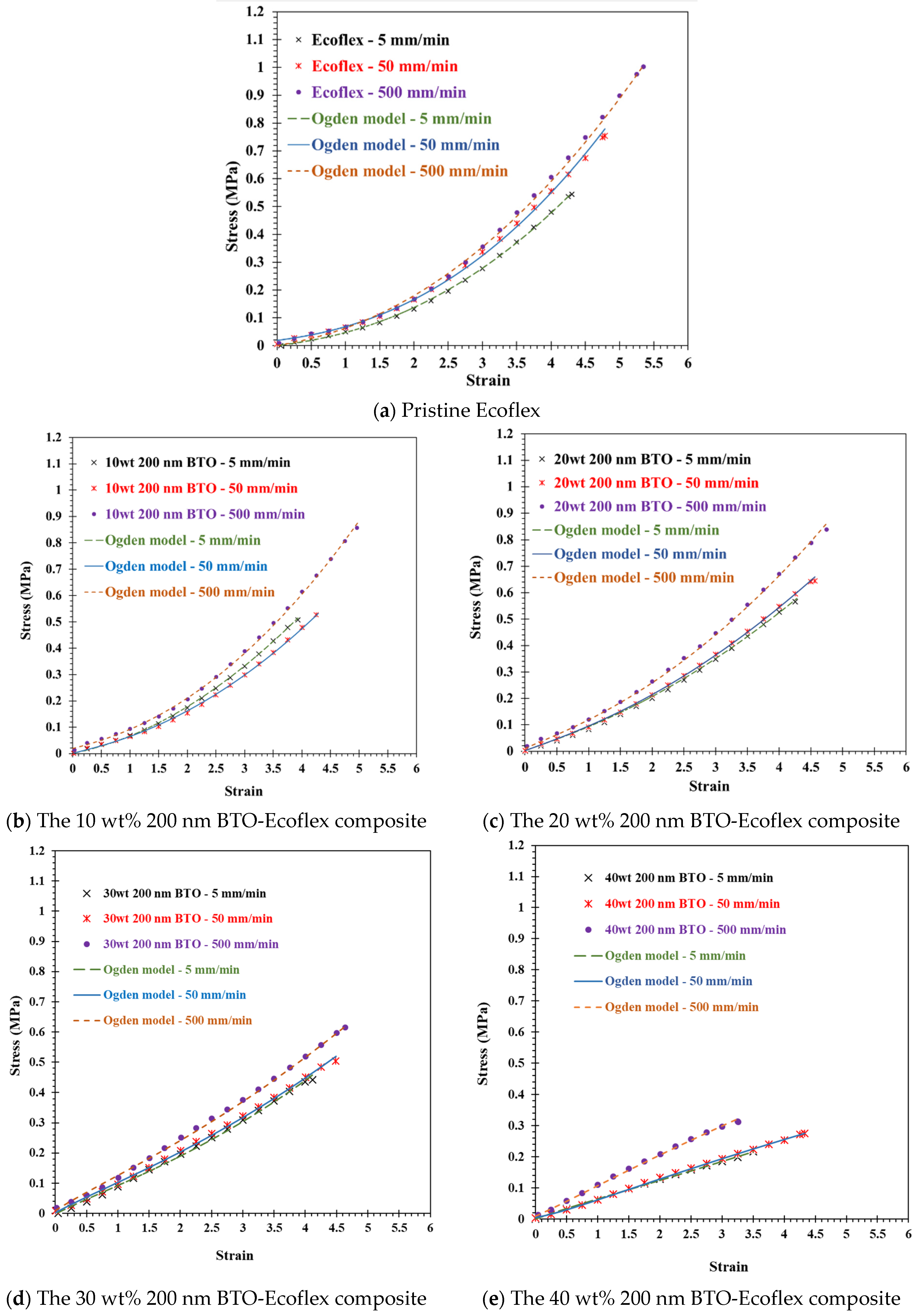
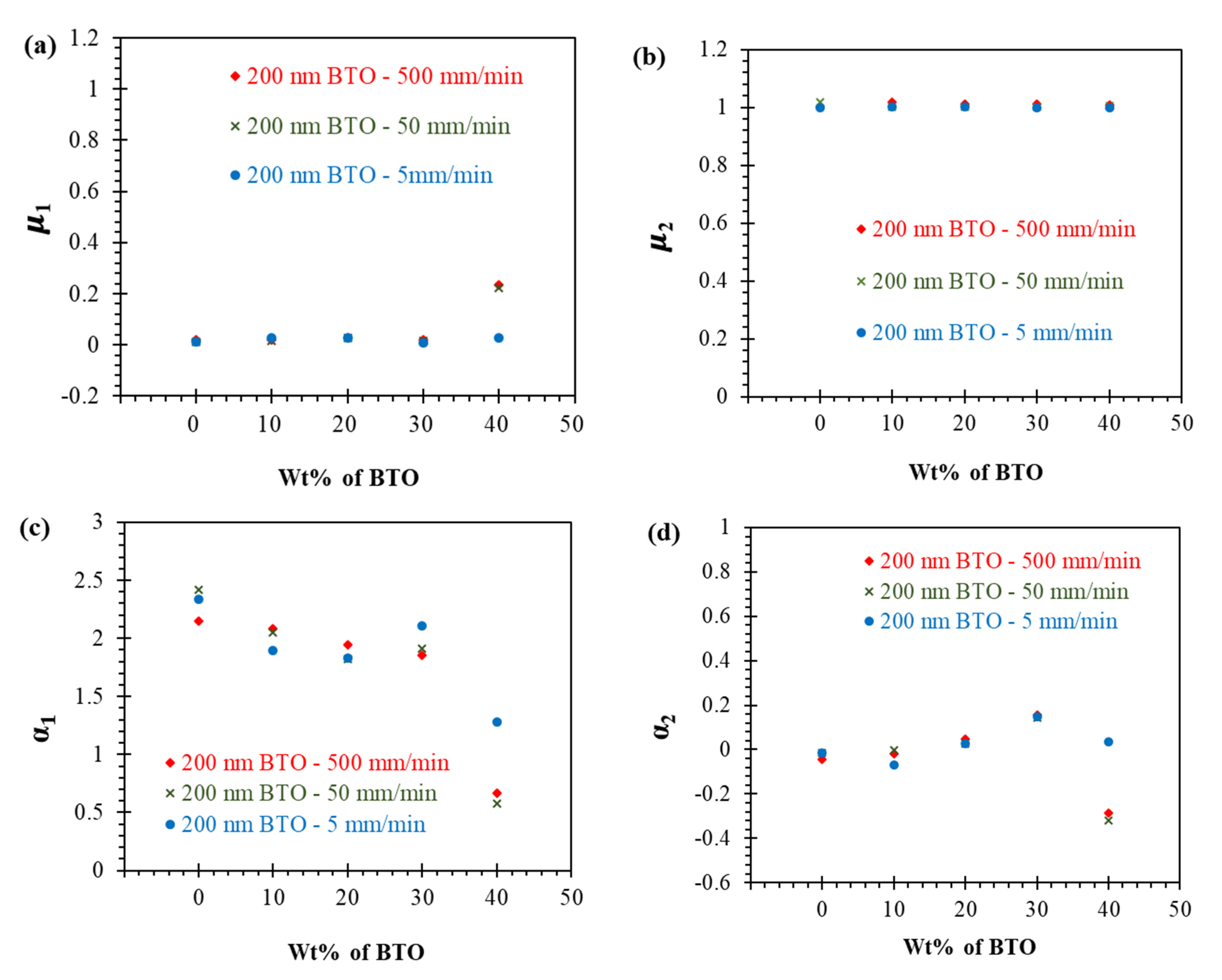
3.3. Stress-Strain Behaviour of BTO-Ecoflex Composite and Ogden Modelling

The non-linear behaviour of elastomeric composites can be studied by performing static tests, such as creep (load constant, strain varies with time), stress relaxation (stress varies with time at a constant strain) or using dynamic tests such as strain rate dependent uniaxial tensile tests. In our earlier study of stress relaxation tests of IDC sensors with the BTO-Ecoflex substrate, it was shown that stress relaxation of the substrate does not influence the output signal of the IDC sensor [38]. The strain rate dependent study also showed similar results as the output signal of IDC sensor with pristine Ecoflex and a 40 wt% 200 nm BTO-Ecoflex substrate show consistent results, which do not vary with the strain rate (see Figure 5 and Figure 6). However, in order to understand the non-linear stress-strain behaviour of BTO-Ecoflex composite during dynamic loading, we performed uniaxial tension testing at ~5, ~50, and ~500 mm/min strain rates up to sample failure. We found that the Ogden model is a suitable model to understand the non-linear stress-strain behaviour of BTO-Ecoflex composite in dynamic tensile loading conditions.
The Ogden model is the most generally used model to describe the non-linear stress-strain behaviour of composite elastomers and has been frequently used for the analysis of rubber components such as O-rings and seals [44]. It can be used for predicting the non-linear stress-strain behaviour of materials such as polymers, biological tissues, and elastomers. The Ogden model, unlike other models such as the Neo-Hookean and Mooney-Rivlin, which are expressed in terms of invariants, is expressed in terms of a strain energy function W which is a function of the three independent variables, the principal stretches λ 1 , λ 2 , and λ 3 . In addition, it is possible to fit the Ogden model to experimental stress-strain test data using, for example, the ABAQUS software, to find the Ogden material parameters. From the literature, the Ogden model shows a good agreement with test data up to 700% strain for tensile test results.
Ecoflex is a silicone based elastomer, and is considered to be incompressible, showing negligible compressibility at even very high strains, up to an axial stretch ratio of 4 [30]. By considering the nearly incompressible behaviour of elastomers, the strain energy density function of an Ogden model is given by Equation (7), by neglecting the contributions of volumetric strain.
W = i = 1 n μ i α i ( λ 1 α i + λ 2 α i + λ 3 α i 3 )
where λ j (j=1,2,3) is the principal stretch, and i is the number of terms considered for the Ogden model. μ i and α i are empirically determined material constants.
For an incompressible material, the three principal stretches ( λ 1 , λ 2 , and λ 3 ) satisfy the constraints given by Equations (8) and (9).
λ 1 λ 2 λ 3 = 1
λ 1 = λ , λ 2 = λ 2 = 1 / λ 1 = 1 / λ
The material is assumed to be isotropic relative to an unstressed undeformed (natural) configuration and its elastic properties are characterized in terms of a strain-energy function W ( λ 1 , λ 2 , λ 3 ) per unit volume, where W depends symmetrically on the stretches subject to Equation (7).
Using the Ogden material model, the three principal values of the Cauchy stresses associated with this deformation are given by Equation (10) and the differentiation of Equation (7) leads to Equation (11).
σ i = λ i W λ i p , I
σ i = p + i = 1 n μ i λ j α i
We now consider an incompressible material under uniaxial tension.
The stretch ratio ‘λ’ (deformed length ‘li’ divided by its initial length ‘lo’) and strain ‘ε’ (change in length ‘li- lo’ divided by original length ‘lo’) are calculated as follows:
λ = l i l 0
ε = Δ l l 0 = l i l 0 l 0
λ = ε + 1
The pressure p is determined from incompressibility and the boundary conditions in uniaxial tension, σ 1 = σ = P / A , where A is a cross sectional area and P is the load, and σ 2 = σ 3 = 0 , yielding:
σ = i = 1 n μ i ( λ α i λ 1 2 α i )
Equation (15) is the simplified Ogden model for an incompressible material under uniaxial tension.
Here, n is the number of terms (order) for the Ogden model, μ i , α i are the material constants of the model, λ j (j = 1,2,3) is a principle stretch ratio, σ j (j = 1,2,3) is the axial stress.
The second-order Ogden model is given by Equation (16), which results from Equations (14) and (15).
σ = μ 1 ( ( ε + 1 ) α 1 ( ε + 1 ) 1 2 α 1 ) + μ 2 ( ( ε + 1 ) α 2 ( ε + 1 ) 1 2 α 2 )
The accuracy of the description of the stress-strain behaviour of real materials depends upon the order of the Ogden model. A best fit Ogden model parameter for each experimental stress-strain curve was obtained using the ABAQUS software and the cftool function in MATLAB. An initial trial and error curve fitting of the stress-strain test data of composite samples showed that the second-order Ogden model is the most suitable order of the Ogden model to describe the stress-strain behaviour of uniaxial tensile testing samples. A second-order Ogden model fit with R-square ~0.99 of the stress-strain data of a BTO-Ecoflex composite is shown in Figure 8.
There is a need to take into account that there will be non-uniqueness in the values of the material parameters, due to the involvement of four material constants in the models for a non-linear elastic response. There is a range of sets of values of the material parameters that can fit the experimental data for various stretches [45]. Ogden et al. stated that the material parameters found from the uniaxial response do not necessarily predict the response for other conditions, for example, biaxial loading at a larger stretch, and vice versa [45]. These mismatches are more relevant for higher order Ogden models. However, the fitting of material parameters for uniaxial loading can provide a good overall fit to the experimental data and help understand the non-linear stress-strain response of the BTO-Ecoflex composite.
The values of the second-order Ogden model parameters are plotted with varying 200 nm BTO filler loading in Figure 9. To evaluate the influence of each parameter of the Ogden model on the non-linear stress-strain response of composites, a study was undertaken at varying strain rates (~5, ~50, and ~500 mm/min) on each sample composition. We have observed that the μ1 and μ2 parameters (related to the modulus in MPa) are almost constant with varying strain rates and filler loading, as can be observed in Figure 9a,b. The α1 and α2 Ogden parameters characterize the degree of non-linearity of the stress-strain response of composites [45,46]. When α1 approaches unity with an increase in filler loading to 40 wt% (see Figure 9c and Equation (15)), there is a decrease in non-linearity of the stress-strain behaviour of the composite. The effect of strain rate on the non-linear elastic behaviour is also seen to be lower at a lower filler loading, as observed in Figure 9c. In addition, it is also evident from Figure 8 that the stress-strain non-linearity of the composites decreases with an increase in matrix filler loading.
While the Ogden model is a macroscale model and thus has the limitation of not being able to explain the precise microscale properties and mechanisms of composites, it is nevertheless useful to predict the non-linear stress-strain behaviour of composites. The several factors at the microscale influencing non-linearity include particle surface area, sedimentation, agglomerations, and the distribution of particles in the matrix.

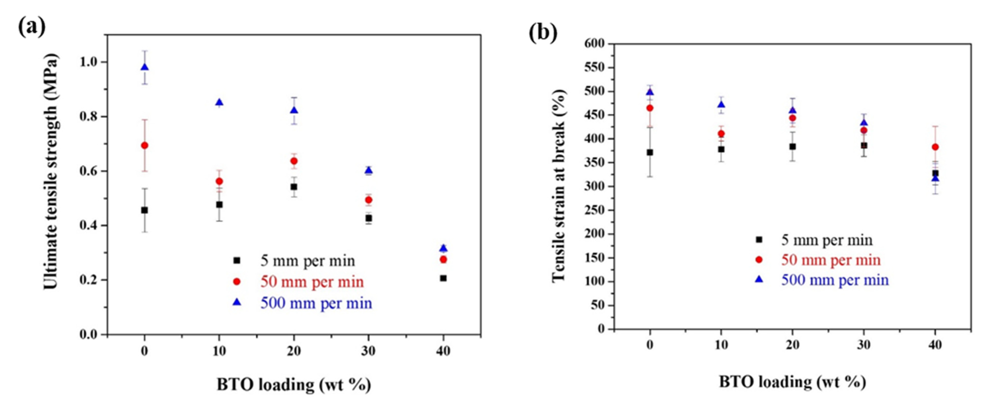
3.4. Ultimate Tensile Strength, Elongation at Breakpoint of 200 nm BTO-Ecoflex Composite

The ultimate tensile strength (UTS) is the maximum stress that a material can withstand before breaking, the strain at this point is the tensile strain at break. The study of UTS and tensile strain at failure of pristine Ecoflex and BTO-Ecoflex composites at different strain rates provides insights into the reinforcement effect of relatively rigid ceramic particles (200 nm BTO) within the matrix (Ecoflex) during dynamic loading conditions. Uniaxial tension testing was performed on pristine Ecoflex and BTO-Ecoflex composites with 10 wt% (volume fraction, Vf = 0.018), 20 wt% (Vf = 0.041), 30 wt% (Vf = 0.068), and 40 wt% (Vf = 0.101) of 200 nm BTO.
The uniaxial tension test to failure is conducted at ~5, ~50, and ~500 mm/min strain rates. A summary of the results for tensile strength and tensile strain at failure show a decrease in strength and failure strain with an increase in the BTO filler, as seen in Figure 10a. This is due to factors (such as the size and surface area of particle, the distribution of particles in the matrix) that decrease the reinforcement mechanical bond due to an increase in the degree of agglomeration of BTO filler in the Ecoflex matrix [47,48].
The pristine Ecoflex and BTO-Ecoflex composites exhibited an increase in strength with an increase in the strain rate (see Figure 10a). This is due to the softening effect of silicone-based elastomer (Ecoflex) with the increasing strain rates [49]. The tensile strain at failure of the composites also increased with an increase in the strain rate (see Figure 10b). The UTS increases (by an average amount of 130%) with an increase in the strain rate. The UTS at ~500 mm/min is increased by nearly twice as large (average 167.3%) over that of ~5 mm/min. It is clear from Figure 10 that the effect of strain rate on the UTS and tensile strain at break decreases with an increase in the loading of the 200 nm BTO. This is due to the more uniform distribution of the 200 nm BTO in Ecoflex at a higher loading (40 wt% BTO-Ecoflex composite), as explained below in relation to the scanning electron microscopy analysis.

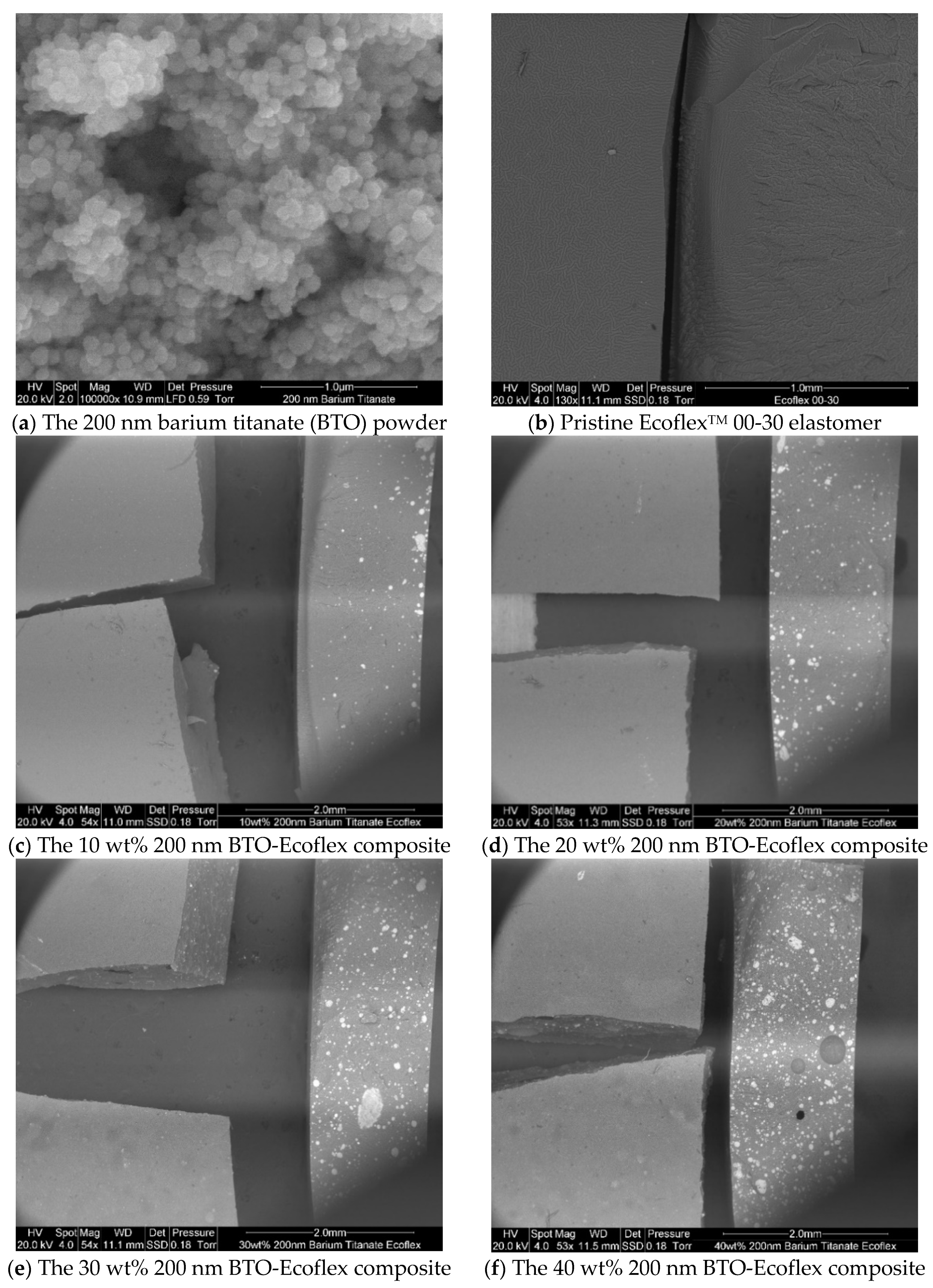
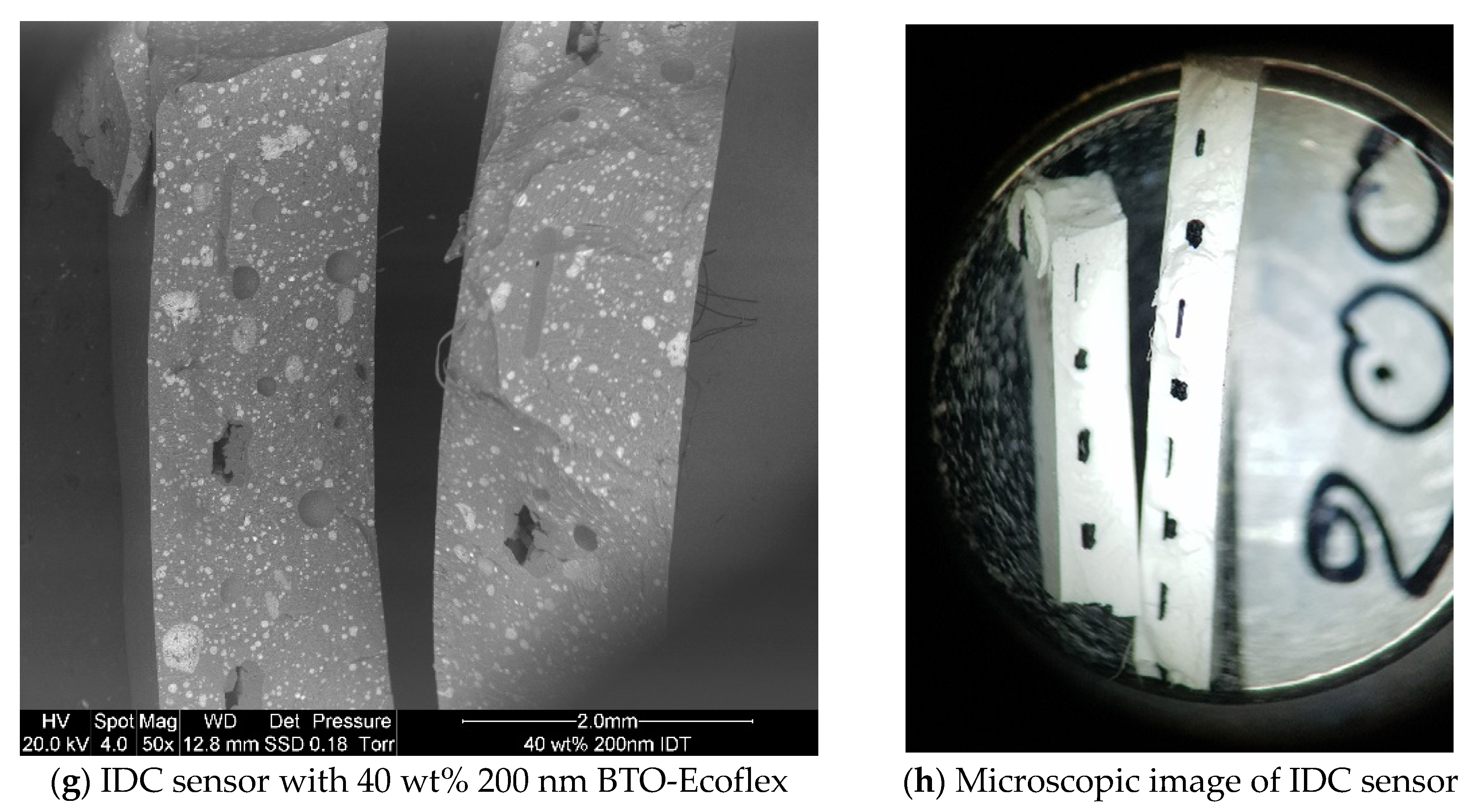
3.5. SEM Analysis of Pristine Ecoflex and 200 nm BTO-Ecoflex Composites

The pristine Ecoflex and BTO-Ecoflex composites with 10, 20, 30, and 40 wt% BTO were cryo-fractured for analysis of the distribution of the 200 nm BTO filler in the Ecoflex matrix using scanning electron microscopy (SEM), an FEI Quanta 200 F model manufactured by FEI company, Dawson creek drive, Hillsboro, USA.
We analyzed the SEM images of 10 wt% (Figure 11c) and 20 wt% (Figure 11d) of BTO-Ecoflex composite, and observed sedementation of the 200 nm BTO filler in the Ecoflex matrix at this lower level of particle loading. The 200 nm BTO filler is more uniformly distributed in the 40 wt% of BTO-Ecoflex composite (Figure 11f) than the 30 wt% of BTO-Ecoflex composite (Figure 11e). Therefore, we have selected the 40 wt% of BTO-Ecoflex composite to fabricate a reliable and robust IDC sensor (see Figure 11g).
While the 40 wt% 200 nm BTO filler exhibits some degree of filler agglomeration due to the high surface area of nanoparticles, the 200 nm BTO filler is mostly uniformly distributed across the Ecoflex matrix, which can be seen in Figure 11f,g. Therefore, the 40 wt% composition represents an optimal balance between achieving a good dispersion, high relative permittivity, and repeatability over large numbers of stretch/relax cycles.

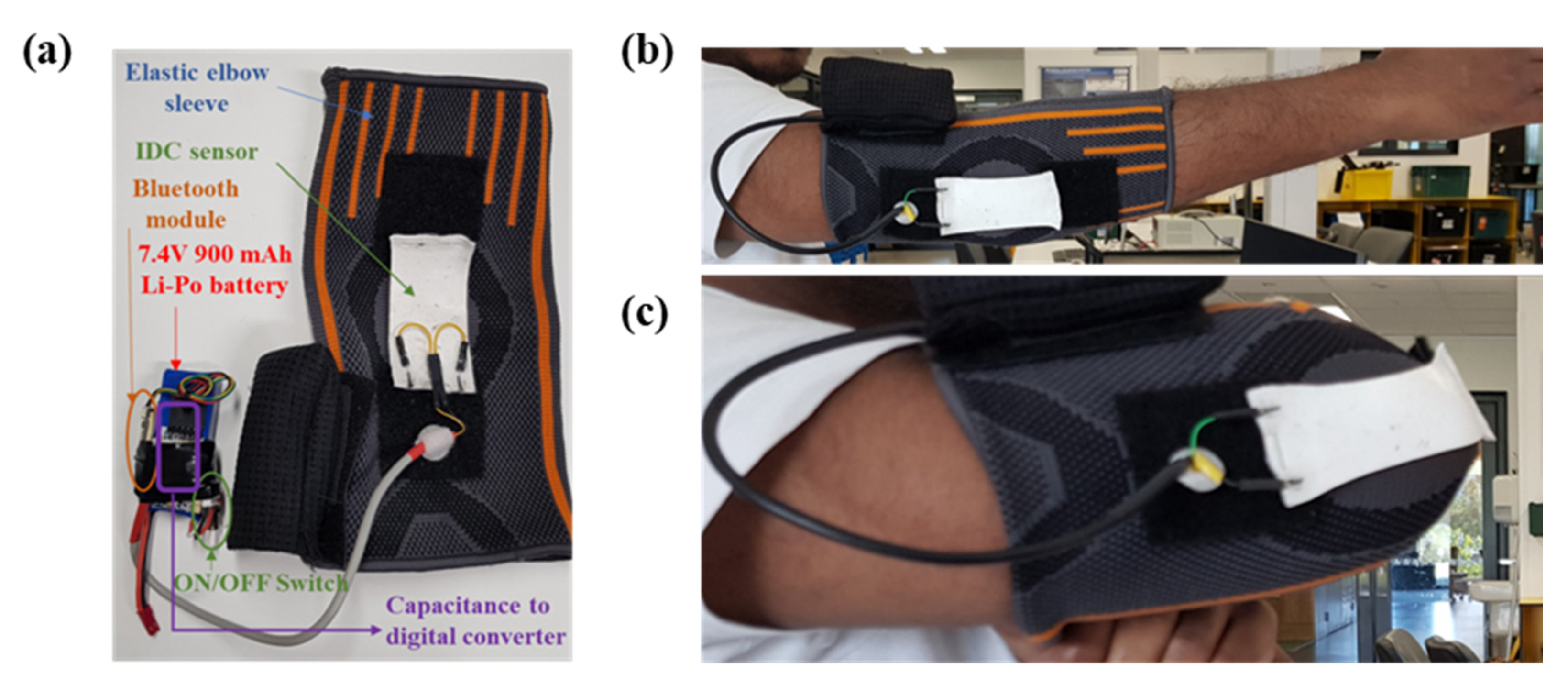
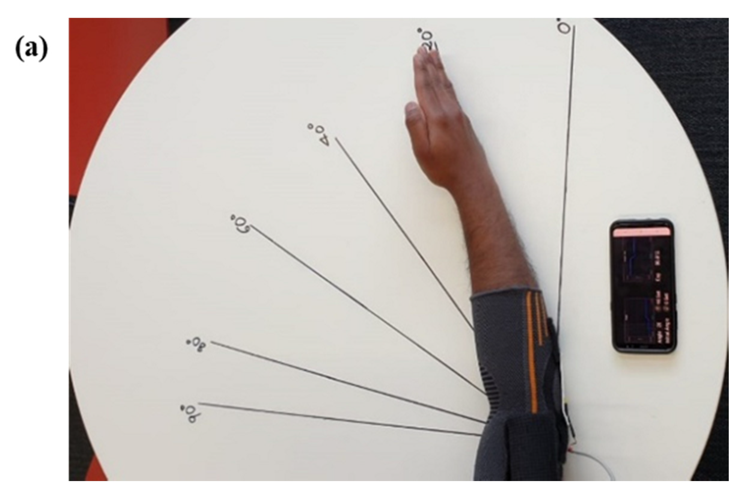
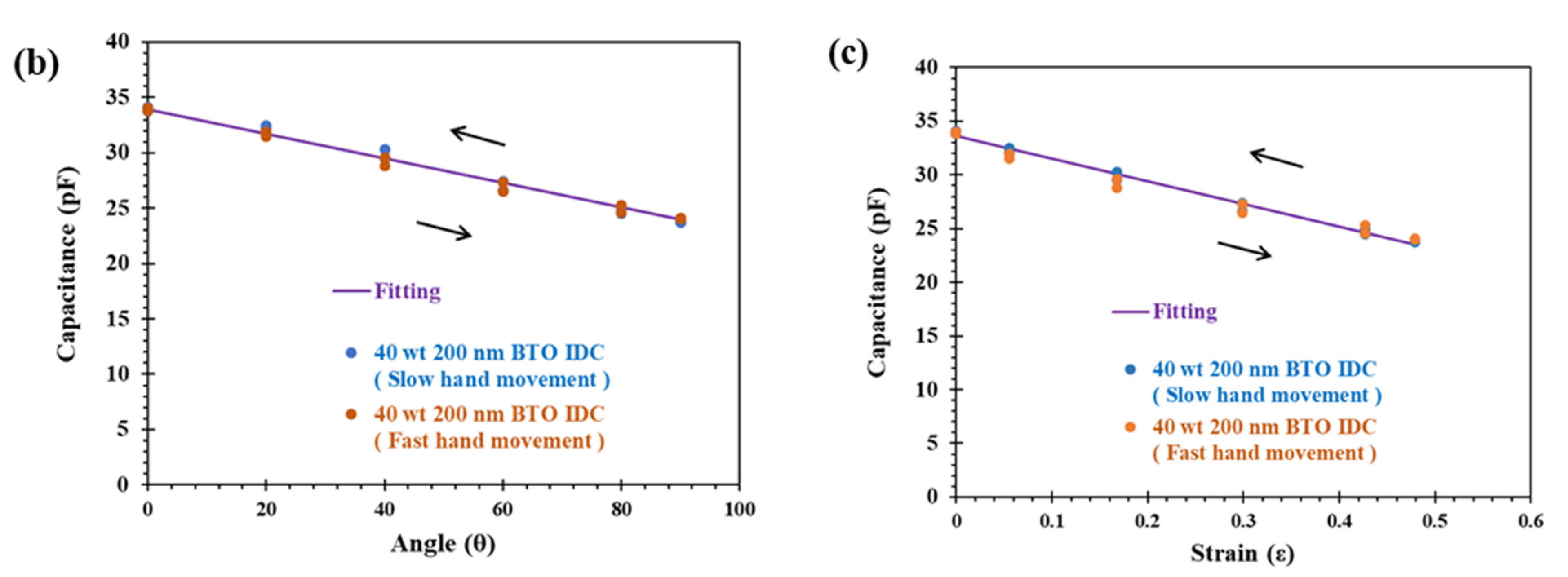
3.6. Application of Stretchable Sensor

The IDC sensor fabricated with the 40 wt% 200 nm BTO-Ecoflex composite substrate shows promising results, with negligible hysteresis up to 1000 stretch/relax cycles at ~50 and ~500 mm/min strain rates, as presented in Figure 6. Therefore, we have selected the IDC sensor with the 40 wt% 200 nm BTO-Ecoflex substrate to develop an application to measure the bending of the elbow irrespective of the hand movement speed.
The IDC strain sensor is mounted on to the elastic elbow sleeve, then connected to the capacitance to a digital converter with the insulated cable and then powered with a 7.4 V, 900 mAh Li-Po rechargeable battery. A Bluetooth module is connected to the converter, which helps connect wirelessly to a mobile app called Bluetooth graphics, which is available in the Google Play store. An elastic sleeve with a sensor is worn on the arm at the elbow, as shown in Figure 12.
The IDC strain sensor with the associated electronics on the elastic sleeve is worn on the right elbow and connected to the Bluetooth graphics app with Bluetooth. Then, the elbow is bent to 0, 20, 40, 60, 80, and 90°, as shown in Figure 13a. The capacitance is recorded at respective marked angles and then recorded as presented in Figure 13b, with the corresponding strain plotted in Figure 13c. The capacitance and the deflection angle of the elbow show an almost linear relationship. The cftool feature in MATLAB is used for curve fitting the capacitance versus angle (θ), and capacitance versus strain (ε) data. The resulting linear relationship is generated as given by Equation (17), with R-square = 0.982 and by Equation (18), with R-square = 0.99, respectively. While the IDC sensor shows some non-linear behaviour at a 100% strain (Figure 7), below the strain level of 50% the IDC sensor with 40 wt% 200 nm BTO-Ecoflex substrate is approximately linear, as shown in Figure 13c.
C = 0.1009 θ + 33.88
C = 21.03 ε + 33.6
In this work, it has been demonstrated that the IDC sensor with the 40 wt% 200 nm BTO-Ecoflex substrate can reliably be used in measuring the bending of an elbow irrespective of the hand movement speed. In the future, this IDC sensor can be customized for use in in various wearable applications, such as virtual reality, soft-robotics, personal health monitoring, human motion detection, and smart clothing systems.
Furthermore, BTO nanoparticles and the Ecoflex are biocompatible and have recently been used as a nano-carrier for drug delivery [50] as well as a skin-safe elastomer used in prosthetic and electronic skin devices for health care applications [51], respectively. Therefore, the IDC strain sensor fabricated with the 40 wt% 200 nm BTO-Ecoflex composite substrate is biocompatible, skin safe, reliable, and robust.

4. Conclusions

An interdigitated capacitive strain sensor is fabricated by sandwiching the printed IDC electrode structure with carbon black ink between the 40 wt% 200 nm BTO-Ecoflex composite substrate. The effect of strain rate on the output signal of IDC sensors with pristine Ecoflex and 200 nm BTO-Ecoflex composites is examined by subjecting the IDC sensor up to 1000 stretch/relax cycles at ~50 and ~500 mm/min strain rates. The IDC sensor fabricated with pristine Ecoflex and a 40 wt% 200 nm BTO-Ecoflex composite has shown a consistent relative change in capacitance up to 1000 stretch/relax cycles. The gauge factor (GF) of IDC sensors based on the 40 wt% 200 nm BTO-Ecoflex composite substrate is higher than the gauge factor of IDC sensor with the pristine Ecoflex substrate. However, the GF of IDC sensors decreases with the strain due to the non-linear relationship between the relative change in capacitance with the strain. Therefore, the GF is measured at 50 and 100% strain of IDC sensors. The advantages of adding the 40 wt% 200 nm BTO filler to the Ecoflex substrate for the IDC sensor are that the relative permittivity of the substrate is increased, which increases the capacitance at a zero strain and also increases the sensitivity of the IDC sensor.
To understand the non-linear elastic behaviour of BTO-Ecoflex composite during dynamic loading conditions, the 0 wt% (pristine Ecoflex) and BTO-Ecoflex composites with 10, 20, 30, and 40 wt% 200 nm BTO were tested for uniaxial testing at 5, 50, and 500 mm/min strain rates. A second-order Ogden model was fitted to the test data using ABAQUS and MATLAB, and the varying material constants of BTO-Ecoflex composite at different strain rates were calculated. The non-linearity in stress-strain response of composites in general decreases with an increase in filler loading, consistent with a decrease in α1 and α2 Ogden parameters.
The ultimate tensile strength and strain at break of BTO-Ecoflex at ~5, ~50, and ~500 mm/min strain rates were studied, where the tensile strength decreased with an increase in the BTO filler in pristine Ecoflex, as well as a decrease in the tensile strain at the break with an increase in BTO loading in Ecoflex. Scanning electron microscopy on the cryo-fractured pristine Ecoflex and BTO-Ecoflex composites with 10, 20, 30 and 40 wt% of BTO revealed that the 200 nm BTO filler is more uniformly distributed at a higher loading (40 wt%) of BTO filler. Thus, a reduced strain-rate effect is observed on the ultimate tensile in the 40 wt% of 200 nm BTO-Ecolfex composite due to the more uniform distribution of BTO in Ecoflex. This might be one of the factors resulting in the lower non-linear stress-strain response during uniaxial tensile loading of 40 wt% BTO-Ecoflex composite in comparison with the 10, 20, and 30 wt% of BTO-Ecoflex composite. An IDC sensor was fabricated with the 40 wt% 200 nm BTO-Ecoflex composite substrate, due to its higher capacitance and sensitivity for demonstrating the application to measure the deflection of elbow angle with the decrease in capacitance with the strain. A linear relationship with respect to the elbow bending angle was observed between the IDC sensor output signal under a 50% strain and deflection of the elbow of the hand indicating its potential as a stretchable and flexible sensor for applications such as soft robotics, etc.

Supplementary Materials

The following are available online at https://www.mdpi.com/article/10.3390/robotics10020069/s1, Supplementary Table S1 (ST 1): literature review of interdigital capacitive strain sensors. Supplementary Table S2 (ST 2): Capacitance and relative permittivity of 40 wt% 200 nm BTO. Supplementary Table S3 (ST 3): The actual dimensions of the printed IDC, dimensions in mm. Supplementary Figure S1 (SF 1): Cross-section view of coplanar strip line with fringing electric field. Supplementary Figure S2 (SF 2): A cross section of the printed carbon black (CB)/Ecoflex electrode. Supplementary Figure S3 (SF 3): SEM image of a cross section of 200 nm BTO–EcoflexTM 00-30 composite substrate and printed CB/Ecoflex electrode. Supplementary Figure S4 (SF 4): IDC sensor with pristine BTO-Ecoflex 00-30TM substrate tested at 0.7 mm per sec, (a) The relative change in capacitance (ΔCS/C0) strained up to 100% after 1, 100, 500 and 1000 stretch/relax cycles. (b) The ΔCS/C0 versus time as the sensor was stretched to 100% strain. Supplementary Figure S5 (SF 5): IDC sensor with pristine BTO-Ecoflex 00-30TM substrate tested at 7 mm per sec, (a) The relative change in capacitance (ΔCS/C0) strained up to 100% after 1, 100, 500 and 1000 stretch/relax cycles. (b) The ΔCS/C0 versus time as the sensor was stretched to 100% strain. Supplementary Figure S6 (SF 6): IDC sensor with 40 wt% 200 nm BTO-Ecoflex 00-30TM substrate tested at 0.7 mm per sec, (a) The relative change in capacitance (ΔCS/C0) strained up to 100% after 1, 100, 500 and 1000 stretch/relax cycles. (b) The ΔCS/C0 versus time as the sensor was stretched to 100% strain. Supplementary Figure S7 (SF 7): IDC sensor with 40 wt% 200 nm BTO-Ecoflex 00-30TM substrate tested at 7 mm per sec, (a) The relative change in capacitance (ΔCS/C0) strained up to 100% after 1, 100, 500 and 1000 stretch/relax cycles. (b) The ΔCS/C0 versus time as the sensor was stretched to 100% strain. Supplementary Figure S8 (SF8): Scanning electron microscope (SEM) analysis of 10 wt%, 20 wt%, 30 wt% and 40 wt% of 200 nm BTO-Ecoflex composite with 1 mm scale of magnification. Supplementary Figure S9 (SF9): Scanning electron microscope (SEM) analysis of 10 wt%, and 40 wt% of 200 nm BTO-Ecoflex composite with 500 μm scale of magnification. Supplementary Figure S10 (SF 10): Flow chart of developing the application with IDC sensor to measure the elbow angle.

Author Contributions

Conceptualization, E.R.C. and P.K.; methodology, E.R.C., P.K., J.S. and K.A.; validation, P.K., C.B., J.S. and K.A.; formal analysis, E.R.C. and P.K.; investigation, E.R.C.; resources, K.A., J.S. and C.B.; data curation, E.R.C.; writing—original draft preparation, E.R.C.; writing—review and editing, J.S., C.B., P.K. and K.A.; visualization, P.K., J.S. and K.A.; supervision, J.S., C.B. and K.A.; project administration, J.S. and K.A. All authors have read and agreed to the published version of the manuscript.

Funding

This research received no external funding.

Institutional Review Board Statement

The study was conducted according to the guidelines approved by The University of Auckland human participants ethics committee.

Informed Consent Statement

Patient consent was waived because the first author is the subject.

Conflicts of Interest

The authors declare no conflict of interest.

References

  1. Cholleti, E.R.; Stringer, J.; Assadian, M.; Battmann, V.; Bowen, C.; Aw, K. Highly Stretchable Capacitive Sen-sor with Printed Carbon Black Electrodes on Barium Titanate Elastomer Composite. Sensors 2019, 19, 42. [Google Scholar] [CrossRef] [Green Version]
  2. Fujimoto, K.T.; Watkins, J.K.; Phero, T.; Litteken, D.; Tsai, K.; Bingham, T.; Ranganatha, K.L.; Johnson, B.C.; Deng, Z.; Jaques, B.; et al. Aerosol jet printed capacitive strain gauge for soft structural materials. npj Flex. Electron. 2020, 4, 1–9. [Google Scholar] [CrossRef]
  3. Zens, M.; Ruhhammer, J.; Goldschmidtboeing, F.; Feucht, M.J.; Bernstein, A.; Niemeyer, P.; Mayr, H.O.; Woias, P. Polydimethylsiloxane strain gauges for biomedical applications. In Proceedings of the 2015 Transducers-2015 18th International Conference on Solid-State Sensors, Actuators and Microsystems (TRANSDUCERS), Anchorage, AK, USA, 21–25 June 2015. [Google Scholar]
  4. Afsarimanesh, N.; Nag, A.; Alahi, E.E.; Han, T.; Mukhopadhyay, S.C. Interdigital sensors: Biomedical, environmental and industrial applications. Sens. Actuators A Phys. 2020, 305, 111923. [Google Scholar] [CrossRef]
  5. Zhao, Y.; Huang, X. Mechanisms and Materials of Flexible and Stretchable Skin Sensors. Micromachines 2017, 8, 69. [Google Scholar] [CrossRef] [Green Version]
  6. Matsuzaki, R.; Keating, T.; Todoroki, A.; Hiraoka, N. Rubber-based strain sensor fabricated using photolithography for intelligent tires. Sens. Actuators A Phys. 2008, 148, 1–9. [Google Scholar] [CrossRef]
  7. Lu, N.; Kim, D.-H. Flexible and Stretchable Electronics Paving the Way for Soft Robotics. Soft Robot. 2014, 1, 53–62. [Google Scholar] [CrossRef]
  8. Yeo, J.C.; Yap, H.K.; Xi, W.; Wang, Z.; Yeow, C.-H.; Lim, C.T. Flexible and Stretchable Strain Sensing Actuator for Wearable Soft Robotic Applications. Adv. Mater. Technol. 2016, 1. [Google Scholar] [CrossRef]
  9. Tan, C.; Dong, Z.; Li, Y.; Zhao, H.; Huang, X.; Zhou, Z.; Jiang, J.-W.; Long, Y.-Z.; Jiang, P.; Zhang, T.-Y.; et al. A high performance wearable strain sensor with advanced thermal management for motion monitoring. Nat. Commun. 2020, 11, 1–10. [Google Scholar] [CrossRef]
  10. Atalay, O.; Atalay, A.; Gafford, J.; Wang, H.; Wood, R.; Walsh, C. A Highly Stretchable Capacitive-Based Strain Sensor Based on Metal Deposition and Laser Rastering. Adv. Mater. Technol. 2017, 2, 1700081. [Google Scholar] [CrossRef]
  11. Xiong, Y.; Shen, Y.; Tian, L.; Hu, Y.; Zhu, P.; Sun, R.; Wong, C.-P. A flexible, ultra-highly sensitive and stable capacitive pressure sensor with convex microarrays for motion and health monitoring. Nano Energy 2020, 70, 104436. [Google Scholar] [CrossRef]
  12. Zhang, P.; Chen, Y.C.; Li, Y.X.; Zhang, Y.; Zhang, J.; Huang, L.S. A Flexible Strain Sensor Based on the Porous Structure of a Carbon Black/Carbon Nanotube Conducting Network for Human Motion Detection. Sensors 2020, 20, 1154. [Google Scholar] [CrossRef] [PubMed] [Green Version]
  13. Shintake, J.; Nagai, T.; Ogishima, K. Sensitivity Improvement of Highly Stretchable Capacitive Strain Sensors by Hierarchical Auxetic Structures. Front. Robot. AI 2019, 6, 127. [Google Scholar] [CrossRef] [Green Version]
  14. Atalay, O. Textile-Based, Interdigital, Capacitive, Soft-Strain Sensor for Wearable Applications. Materials 2018, 11, 768. [Google Scholar] [CrossRef] [PubMed] [Green Version]
  15. Shintake, J.; Piskarev, E.; Jeong, S.H.; Floreano, D. Ultrastretchable Strain Sensors Using Carbon Black-Filled Elastomer Composites and Comparison of Capacitive Versus Resistive Sensors. Adv. Mater. Technol. 2018, 3, 1700284. [Google Scholar] [CrossRef] [Green Version]
  16. Liu, X.; Feng, S.; Chen, X.; Zhao, Y. Research Technologies of Projected Capacitive Touch Screen. In Proceedings of the 2015 5th International Conference on Computer Sciences and Automation Engineering, Sanya, China, 14–15 November 2015; pp. 63–68. [Google Scholar]
  17. Wada, S.; Hoshina, T.; Yasuno, H.; Nam, S.M.; Kakemoto, H.; Tsurumi, T.; Yashima, M. Size dependence of dielectric properties for nm-sized barium titanate crystallites and its origin. J. Korean Phys. Soc. 2005, 46, 303–307. [Google Scholar]
  18. Wada, S.; Yasuno, H.; Hoshina, T.; Nam, S.-M.; Kakemoto, H.; Tsurumi, T. Preparation of nm-Sized Barium Titanate Fine Particles and Their Powder Dielectric Properties. Jpn. J. Appl. Phys. 2003, 42, 6188–6195. [Google Scholar] [CrossRef]
  19. Paul, S.; Kumar, D.; Gagandeep, M. Barium titanate as a ferroelectric and piezoelectric ceramics. J. Biosphere. 2013, 2, 55–58. [Google Scholar]
  20. Cholleti, E.R.; Stringer, J.; Kelly, P.; Bowen, C.; Aw, K. The effect of barium titanate ceramic loading on the stress relaxation behavior of barium titanate-silicone elastomer composites. Polym. Eng. Sci. 2020, 60, 3086–3094. [Google Scholar] [CrossRef]
  21. Cholleti, E.R.; Stringer, J.; Bowen, C.; Lo, C.-Y.; Aw, K. Barium Titanate Elastomer composite based capacitive stretch sensor. In Proceedings of the 2019 IEEE/ASME International Conference on Advanced Intelligent Mechatronics (AIM), Hong Kong, China, 8–12 July 2019; pp. 1233–1237. [Google Scholar]
  22. Tesla, N. Electrical Condenser. Google Patents US464667A, 8 December 1891. [Google Scholar]
  23. Love, A.E.H. Some Electrostatic Distributions in two Dimensions. Proc. Lond. Math. Soc. 1924, 2, 337–369. [Google Scholar] [CrossRef]
  24. Mortley, W.S. Pulse Compression by Dispersive Gratings on Crystal Quartz. Marconi Rev. 1965, 28, 273–290. [Google Scholar]
  25. Alley, G. Interdigital Capacitors and Their Application to Lumped-Element Microwave Integrated Circuits. IEEE Trans. Microw. Theory Tech. 1970, 18, 1028–1033. [Google Scholar] [CrossRef]
  26. Li, J.; Longtin, J.P.; Tankiewicz, S.; Gouldstone, A.; Sampath, S. Interdigital capacitive strain gauges fabricated by direct-write thermal spray and ultrafast laser micromachining. Sens. Actuators A Phys. 2007, 133, 1–8. [Google Scholar] [CrossRef]
  27. Zeiser, R.; Fellner, T.; Wilde, J. Capacitive strain gauges on flexible polymer substrates for wireless, intelligent systems. J. Sens. Sens. Syst. 2014, 3, 77–86. [Google Scholar] [CrossRef] [Green Version]
  28. Shin, H.-S.; Bergbreiter, S. Effect of finger geometries on strain response of interdigitated capacitor based soft strain sensors. Appl. Phys. Lett. 2018, 112, 044101. [Google Scholar] [CrossRef]
  29. Houghton, T.; Vanjaria, J.; Murphy, T.; Yu, H. Stretchable Capacitive Strain Sensors Based on a Novel Polymer Composite Blend. In Proceedings of the 2017 IEEE 67th Electronic Components and Technology Conference (ECTC), Orlando, FL, USA, 30 May–2 June 2017; pp. 2263–2268. [Google Scholar]
  30. Steck, D.; Qu, J.; Kordmahale, S.B.; Tscharnuter, D.; Muliana, A.; Kameoka, J. Mechanical responses of Ecoflex silicone rubber: Compressible and incompressible behaviors. J. Appl. Polym. Sci. 2019, 136, 47025. [Google Scholar] [CrossRef]
  31. Kim, B.; Lee, S.B.; Lee, J.; Cho, S.; Park, H.; Yeom, S.; Park, S.H. A comparison among Neo-Hookean model, Mooney-Rivlin model, and Ogden model for chloroprene rubber. Int. J. Precis. Eng. Manuf. 2012, 13, 759–764. [Google Scholar] [CrossRef]
  32. Choi, D.Y.; Kim, M.H.; Oh, Y.S.; Jung, S.-H.; Jung, J.H.; Sung, H.J.; Lee, H.W.; Lee, H.M. Highly Stretchable, Hysteresis-Free Ionic Liquid-Based Strain Sensor for Precise Human Motion Monitoring. ACS Appl. Mater. Interfaces 2017, 9, 1770–1780. [Google Scholar] [CrossRef] [PubMed]
  33. Tobajas, R.; Elduque, D.; Ibarz, E.; Javierre, C.; Canteli, A.F.; Gracia, L. Visco-Hyperelastic Model with Damage for Simulating Cyclic Thermoplastic Elastomers Behavior Applied to an Industrial Component. Polymers 2018, 10, 668. [Google Scholar] [CrossRef] [PubMed] [Green Version]
  34. Ju, M.; Jmal, H.; Dupuis, R.; Aubry, E. Visco-hyperelastic constitutive model for modeling the quasi-static behavior of polyurethane foam in large deformation. Polym. Eng. Sci. 2014, 55, 1795–1804. [Google Scholar] [CrossRef] [Green Version]
  35. Bai, Y.; Liu, C.; Huang, G.; Li, W.; Feng, S. A Hyper-Viscoelastic Constitutive Model for Polyurea under Uniaxial Compressive Loading. Polymers 2016, 8, 133. [Google Scholar] [CrossRef] [PubMed]
  36. Jacob, G.C.; Starbuck, J.M.; Fellers, J.F.; Simunovic, S.; Boeman, R.G. Strain rate effects on the mechanical properties of polymer composite materials. J. Appl. Polym. Sci. 2004, 94, 296–301. [Google Scholar] [CrossRef]
  37. Cholleti, E.R.; Stringer, J.; Kelly, P.; Bowen, C.; Aw, K. Studying the creep behaviour of strechable capacitive sensor with barium titanate silicone elastomer composite. Sens. Actuators A Phys. 2021, 319, 112560. [Google Scholar] [CrossRef]
  38. Chen, J.Z.; Darhuber, A.A.; Troian, S.M.; Wagner, S. Capacitive sensing of droplets for microfluidic devices based on thermocapillary actuation. Lab A Chip 2004, 4, 473–480. [Google Scholar] [CrossRef] [PubMed] [Green Version]
  39. Qin, H.; Cai, Y.; Dong, J.; Lee, Y.-S. Direct Printing of Capacitive Touch Sensors on Flexible Substrates by Additive E-Jet Printing with Silver Nanoinks. In Proceedings of the Asme 11th International Manufacturing Science and Engineering Conference, Blacksburg, WV, USA, 27 June–1 July 2016. [Google Scholar]
  40. Popielarz, R.; Chiang, C.K.; Nozaki, A.R.; Obrzut, J. Dielectric Properties of Polymer/Ferroelectric Ceramic Composites from 100 Hz to 10 GHz. Macromolecules 2001, 34, 5910–5915. [Google Scholar] [CrossRef]
  41. Eom, S.; Lim, S. Stretchable Complementary Split Ring Resonator (CSRR)-Based Radio Frequency (RF) Sensor for Strain Direction and Level Detection. Sensors 2016, 16, 1667. [Google Scholar] [CrossRef] [PubMed]
  42. Kim, S.-R.; Kim, J.-H.; Park, J.-W. Wearable and Transparent Capacitive Strain Sensor with High Sensitivity Based on Patterned Ag Nanowire Networks. ACS Appl. Mater. Interfaces 2017, 9, 26407–26416. [Google Scholar] [CrossRef] [PubMed]
  43. Faisal, A.I.; Majumder, S.; Mondal, T.; Cowan, D.; Naseh, S.; Deen, M.J. Monitoring Methods of Human Body Joints: State-of-the-Art and Research Challenges. Sensors 2019, 19, 2629. [Google Scholar] [CrossRef] [Green Version]
  44. Cassenti, B.N.; Staroselsky, A. Deformation and stability of compressible rubber O-rings. Int. J. Mech. Mater. Eng. 2017, 12, 1–13. [Google Scholar] [CrossRef] [Green Version]
  45. Ogden, R.W.; Saccomandi, G.; Sgura, I. Fitting hyperelastic models to experimental data. Comput. Mech. 2004, 34, 484–502. [Google Scholar] [CrossRef] [Green Version]
  46. Bidhendi, A.J.; Li, H.; Geitmann, A. Modeling the nonlinear elastic behavior of plant epidermis. Botany 2020, 98, 49–64. [Google Scholar] [CrossRef] [Green Version]
  47. Bhagyashekar, M.; Rao, R. Characterization of Mechanical Behavior of Metallic and Non-metallic Particulate Filled Epoxy Matrix Composites. J. Reinf. Plast. Compos. 2008, 29, 30–42. [Google Scholar] [CrossRef]
  48. Kumar, A.; Ahmad, D.; Patra, K. Barium titanate particle filled silicone elastomer composite: Preparation and evaluation of morphology and mechanical behaviour. J. Phys. Conf. Ser. 2019, 1240, 012049. [Google Scholar] [CrossRef]
  49. Case, J.C.; White, E.L.; Kramer, R.K. Soft Material Characterization for Robotic Applications. Soft Robot. 2015, 2, 80–87. [Google Scholar] [CrossRef]
  50. Genchi, G.G.; Marino, A.; Rocca, A.; Mattoli, V.; Ciofani, G. Barium titanate nanoparticles: Promising multitasking vectors in nanomedicine. Nanotechnology 2016, 27, 232001. [Google Scholar] [CrossRef] [PubMed]
  51. Ma, Z.; Li, S.; Wang, H.; Cheng, W.; Li, Y.; Pan, L.; Shi, Y. Advanced electronic skin devices for healthcare applications. J. Mater. Chem. B 2019, 7, 173–197. [Google Scholar] [CrossRef] [PubMed]
Figure 1. (a) BaTiO3 (BTO)-EcoflexTM 00-30 substrate, (b) printing interdigitated capacitor (IDC) with CB/EcoflexTM 00-30 ink (c) customized Lulzbot® photo polymer extrusion (PPE) 3D printer, (d) stretchable capacitive strain sensor, (e) designed dimensions of the printed IDC (dimensions are in mm), (f) gradual transition from a parallel plate capacitor to a planar capacitor.
Robotics 10 00069 g001
Figure 2. BTO-EcoflexTM composite preparation process.
Robotics 10 00069 g002
Figure 3. (a) Rig to characterize the capacitance (Agilent 4263 LCR meter) as a function of strain, (b) sensor being stretched by the motorized stage, (c) schematic of the construction of a sensor.
Robotics 10 00069 g003
Figure 4. (a). Instron 5567 uniaxial testing machine frame with Interface SM-50N SN: 625735 load cell and video extensometer. (b). Test sample marked to represent the gauge length.
Robotics 10 00069 g004
Figure 5. IDC sensor with a pristine Ecoflex 00−30TM substrate strained up to 100%, (a) the relative change in capacitance (ΔCS/C0) during the first stretch/relax cycle at ~50 and ~500 mm/min strain rates, (b) the ΔCS/C0 versus time for the 1000th stretch/relax cycle at ~50 and ~500 mm/min strain rates.
Robotics 10 00069 g005
Figure 6. IDC sensor with a 40 wt% 200 nm BTO-Ecoflex 00-30TM substrate strained up to 100%, (a) the relative change in capacitance (ΔCS/C0) during the first stretch/relax cycle at ~50 and ~500 mm/min strain rates, (b) the ΔCS/C0 versus time for the 1000th stretch/relax cycle at ~50 and ~500 mm/min strain rates.
Robotics 10 00069 g006
Figure 7. (a) Relative change in capacitance (ΔCS/C0) of the IDC sensor strained up to 100% of the first stretch/relax cycle at a ~500 mm/min strain rate. (b) Curve fitting the ΔCS/C0 versus strain during the first stretch cycle of the IDC sensor at a ~500 mm/min strain rate using Equation (6).
Robotics 10 00069 g007
Figure 8. Uniaxial tensile test results for ~5, ~50, and ~500 mm/min strain rates of BTO-Ecoflex composite, fitted with the second-order Ogden model. (a) Pristine Ecoflex 00-30TM, (b) 10 wt% 200 nm BTO-Ecoflex, (c) 20 wt% 200 nm BTO-Ecoflex, (d) 30 wt% 200 nm BTO-Ecoflex, (e) 40 wt% 200 nm BTO-Ecoflex.
Robotics 10 00069 g008
Figure 9. Material parameters for the second-order Ogden model of pristine Ecoflex and 200 nm BTO-Ecoflex composites, (a) μ1 versus wt% of BTO, (b) μ2 versus wt% of BTO, (c) α1 versus wt% of BTO, and (d) α2 versus wt% of BTO.
Robotics 10 00069 g009
Figure 10. Results for uniaxial tensile testing of pristine Ecoflex and 200 nm BTO-Ecoflex composites at ~5, ~50, and ~100 mm/min strain rates, (a) ultimate tensile strength versus BTO loading, (b) the tensile strain at break versus BTO loading.
Robotics 10 00069 g010
Figure 11. Scanning electron microscope (SEM) analysis of (a) 200 nm barium titanate (BTO) powder, (b) pristine silicone based elastomer (EcoflexTM 00-30), (c) 10 wt% 200 nm BTO-Ecoflex composite, (d) 20 wt% 200 nm BTO-Ecoflex composite, (e) 30 wt% 200 nm BTO-Ecoflex composite, (f) 40 wt% 200 nm BTO-Ecoflex composite, (g) IDC sensor with 40 wt% 200 nm BTO-Ecoflex substrate, (h) microscopic image of cryo-fractured IDC sensor with 40 wt% 200 nm BTO-Ecoflex substrate (the black rectangles are the IDC electrode fingers).
Robotics 10 00069 g011aRobotics 10 00069 g011b
Figure 12. (a) The sleeve with the sensor and Bluetooth module, (b) the sleeve with the arm extended, (c) the sleeve with the elbow bent.
Robotics 10 00069 g012
Figure 13. (a) Demonstration of measuring the elbow angle with a reference angled scale, (b) the measured capacitance versus angle (θ) deflection of the elbow, (c) the measured capacitance versus strain (ε) due to deflection of the elbow.
Robotics 10 00069 g013aRobotics 10 00069 g013b
Table 1. Gauge factor of IDC sensors at 50 and 100% strain at a ~500 mm/min strain rate.
Substrate Material of IDCCapacitance of IDC (pF) at 0% StrainGauge Factor (G.F)
at 50 % Strainat 100 % Strain
Pristine Ecoflex 00-3013.27−0.53−0.39
40 wt% 200 nm BTO31.4−0.62−0.45
Publisher’s Note: MDPI stays neutral with regard to jurisdictional claims in published maps and institutional affiliations.

