
High-Precision Measurements of the Bound Electron’s Magnetic Moment

Abstract
:1. Introduction
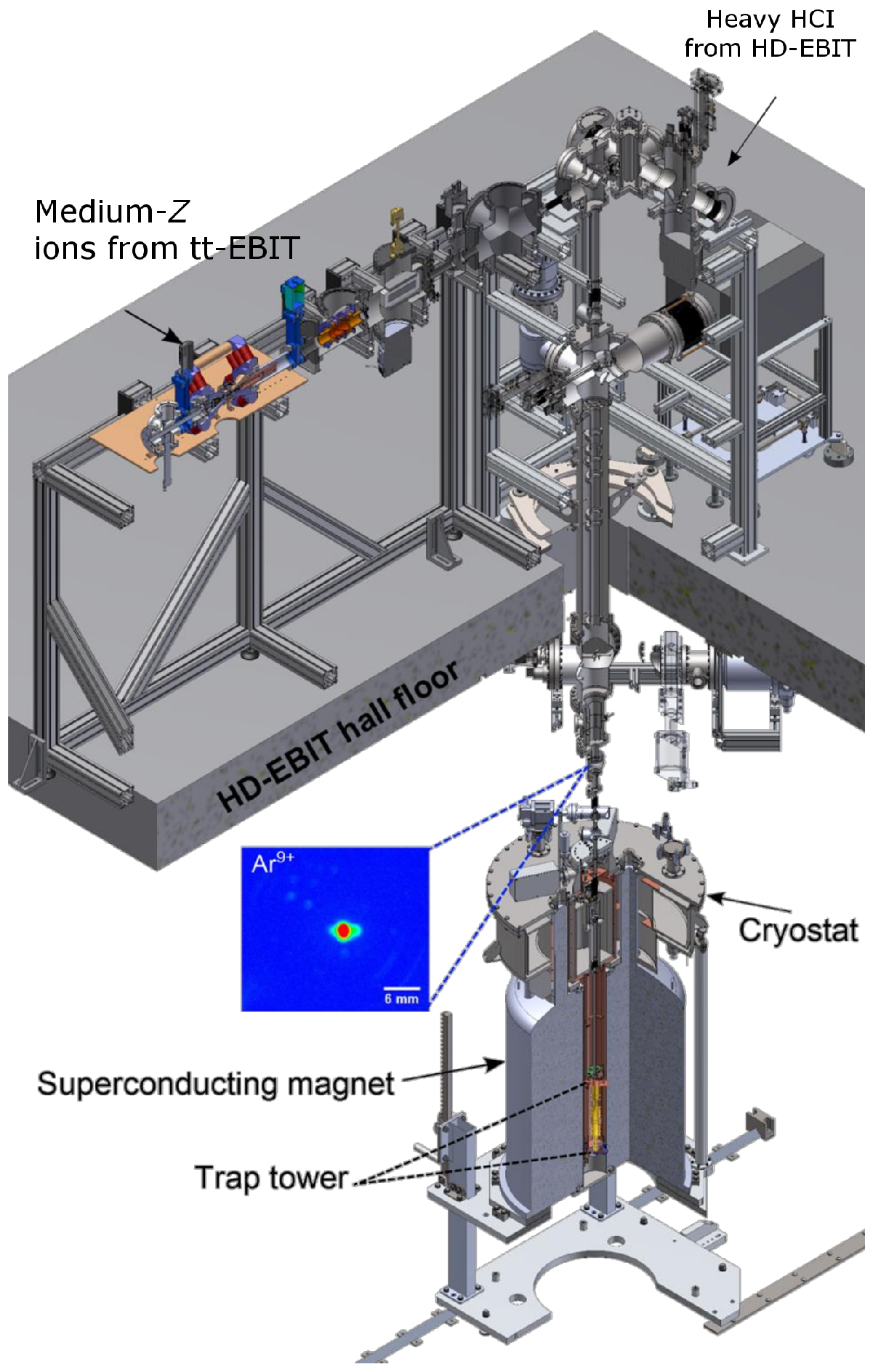
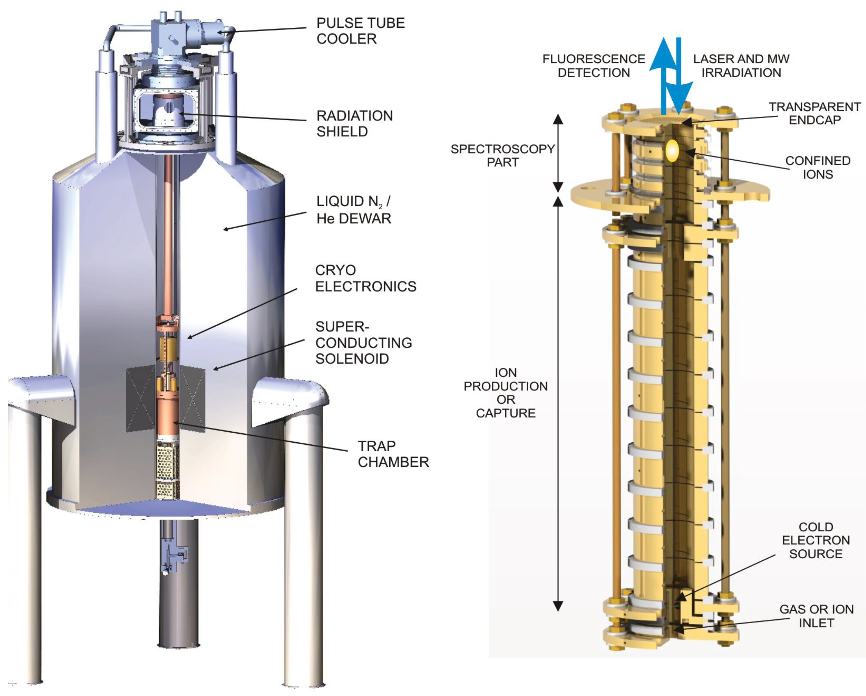
2. Sources of Highly Charged Ions
3. -Factor Measurements with Highly Charged Ions
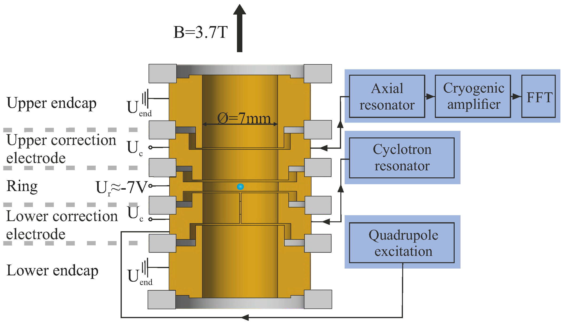
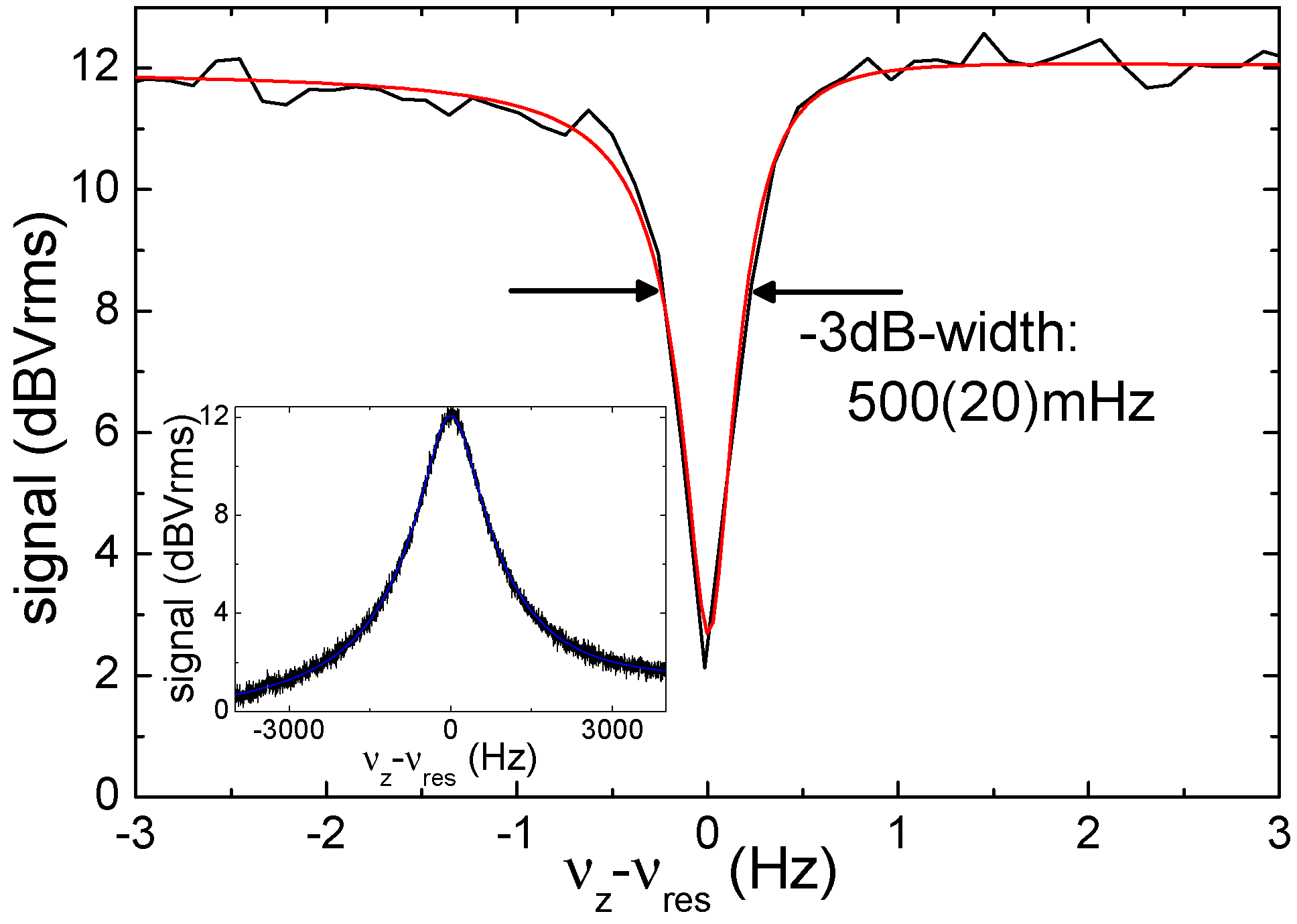
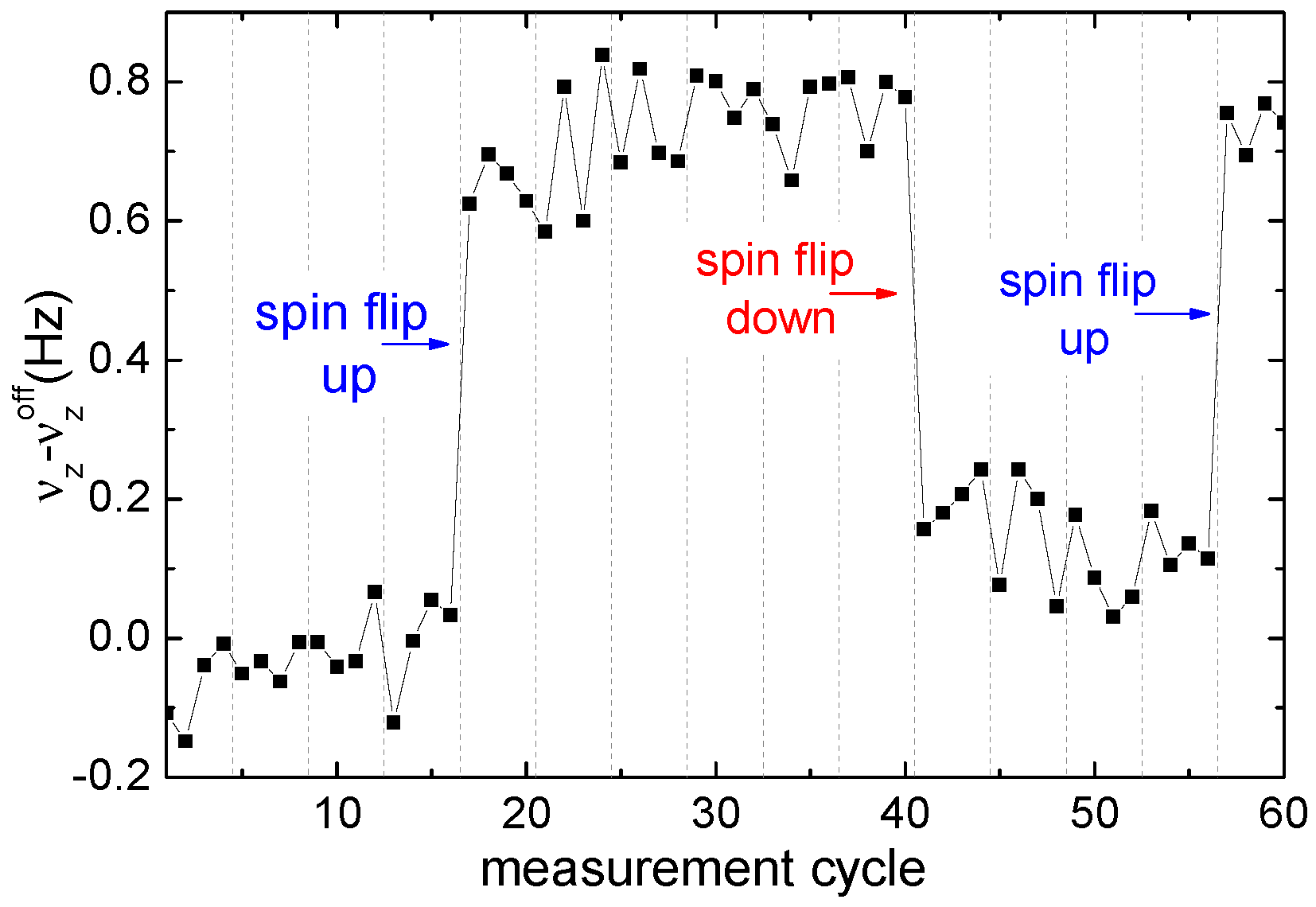
3.1. Mainz g-Factor Experiment
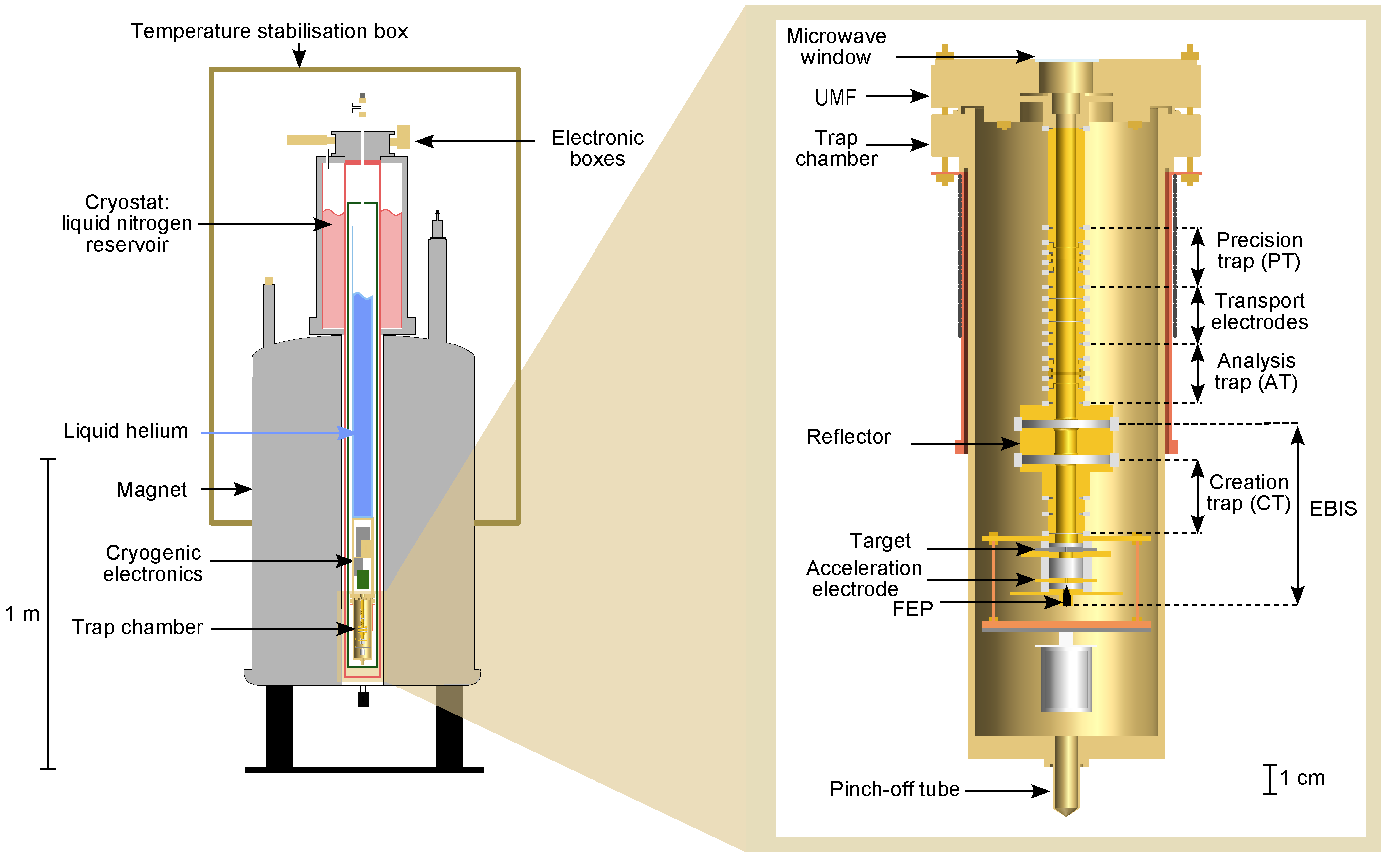
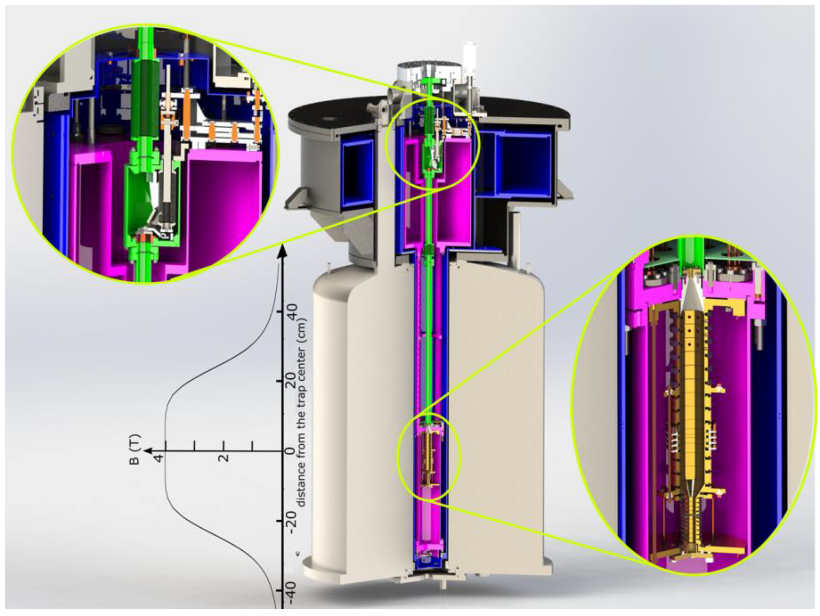
3.2. ALPHATRAP
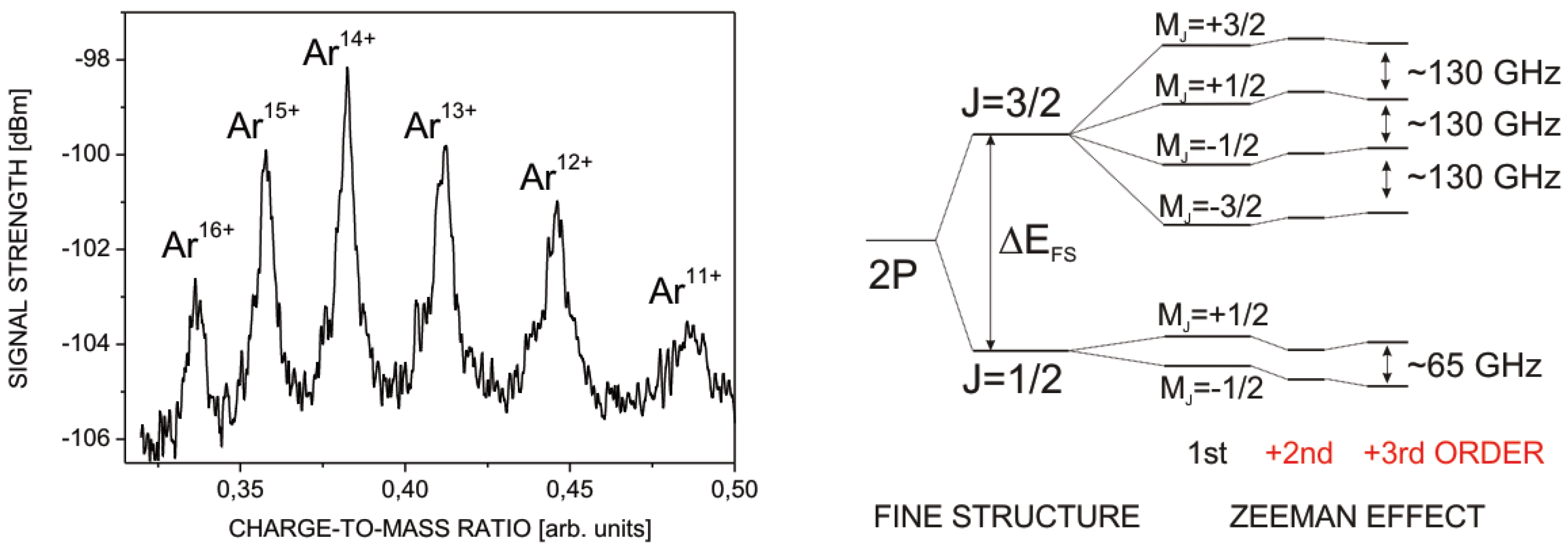
3.3. ARTEMIS
4. Conclusions and Outlook
Author Contributions
Conflicts of Interest
References
- Dirac, P.A.M. The Quantum Theory of the Electron. Proc. R. Soc. A 1928, 117, 610–624. [Google Scholar] [CrossRef]
- Kusch, P.; Foley, H.M. Precision Measurement of the Ratio of the Atomic g Values in the 2P3/2 and 2P1/2 States of Gallium. Phys. Rev. 1947, 72, 1256. [Google Scholar] [CrossRef]
- Kusch, P.; Foley, H.M. On the Intrinsic Moment of the Electron. Phys. Rev. 1948, 74, 250. [Google Scholar] [CrossRef]
- Schwinger, J. On Quantum-Electrodynamics and the Magnetic Moment of the Electron. Phys. Rev. 1948, 73, 416. [Google Scholar] [CrossRef]
- Vogel, M.; Quint, W. Magnetic Moment of the bound electron. In Fundamental Physics in Particle Traps; Springer Tracts in Modern Physics; Springer: Berlin/Heidelberg, Germany, 2014; Volume 256. [Google Scholar]
- Vogel, M. The anomalous magnetic moment of the electron. Contemp. Phys. 2009, 50, 437–452. [Google Scholar] [CrossRef]
- Van Dyck, R.S.; Schwinberg, P.B.; Dehmelt, H.G. New high-precision comparison of electron and positron g factors. Phys. Rev. Lett. 1987, 59, 26. [Google Scholar] [CrossRef] [PubMed]
- Hanneke, D.; Fogwell, S.; Gabrielse, G. New measurement of the electron magnetic moment and the fine structure constant. Phys. Rev. Lett. 2008, 100, 120801. [Google Scholar] [CrossRef] [PubMed]
- Kinoshita, T.; Nio, M. Tenth-order QED contribution to the lepton g − 2: Evaluation of dominant α5 terms of muon g − 2. Phys. Rev. D 2006, 73, 053007. [Google Scholar] [CrossRef]
- Bouchendira, R.; Cladé, P.; Guellati-Khélifa, S.; Nez, F.; Biraben, F. New Determination of the Fine Structure Constant and Test of the Quantum Electrodynamics. Phys. Rev. Lett. 2011, 106, 080801. [Google Scholar] [CrossRef] [PubMed]
- Breit, G. The Magnetic Moment of the Electron. Nature 1928, 122, 649. [Google Scholar] [CrossRef]
- Beier, T. The gj factor of a bound electron and the hyperfine structure splitting in hydrogen-like ions. Phys. Rep. 2000, 339, 79–213. [Google Scholar] [CrossRef]
- Yerokhin, V.A.; Pachucki, K.; Harman, Z.; Keitel, C.H. QED Theory of the Nuclear Magnetic Shielding in Hydrogenlike Ions. Phys. Rev. Lett. 2011, 107, 043004. [Google Scholar] [CrossRef] [PubMed]
- Zatorski, J.; Oreshkina, N.S.; Keitel, C.H.; Harman, Z. Nuclear Shape Effect on the g Factor of Hydrogenlike Ions. Phys. Rev. Lett. 2012, 108, 063005. [Google Scholar] [CrossRef] [PubMed]
- Shabaev, V.M. QED theory of the nuclear recoil effect on the atomic g-factor. Phys. Rev. A 2001, 64, 052104. [Google Scholar] [CrossRef]
- Shabaev, V.M.; Yerokhin, V.A. Recoil Correction to the Bound-Electron g-Factor in H-Like Atoms to All Orders in αZ. Phys. Rev. Lett. 2002, 88, 091801. [Google Scholar] [CrossRef] [PubMed]
- Yerokhin, V.A.; Indelicato, P.; Shabaev, V.M. Self-energy correction to the bound-electron g factor in H-like ions. Phys. Rev. Lett. 2002, 89, 143001. [Google Scholar] [CrossRef] [PubMed]
- Yerokhin, V.A.; Indelicato, P.; Shabaev, V.M. Evaluation of the self-energy correction to the g factor of S states in H-like ions. Phys. Rev. A 2004, 69, 052503. [Google Scholar] [CrossRef]
- Glazov, D.A.; Shabaev, V.M.; Tupitsyn, I.I.; Volotka, A.V.; Yerokhin, V.A.; Plunien, G.; Soff, G. Relativistic and QED corrections to the g factor of Li-like ions. Phys. Rev. A 2004, 70, 062104. [Google Scholar] [CrossRef]
- Volotka, A.V.; Glazov, D.A.; Shabaev, V.M.; Tupitsyn, I.I.; Plunien, G. Screened QED corrections in lithiumlike heavy ions in the presence of magnetic fields. Phys. Rev. Lett. 2009, 103, 033005. [Google Scholar] [CrossRef] [PubMed]
- Glazov, D.A.; Volotka, A.V.; Shabaev, V.M.; Tupitsyn, I.I.; Plunien, G. Evaluation of the screened QED corrections to the g factor and the hyperfine splitting of lithiumlike ions. Phys. Rev. A 2010, 81, 062112. [Google Scholar] [CrossRef]
- Shabaev, V.M.; Andreev, O.V.; Bondarev, A.I.; Glazov, D.A.; Kozhedub, Y.S.; Maiorova, A.V.; Plunien, G.; Tupitsyn, I.I.; Volotka, A.V. Quantum Electrodynamics Effects in Heavy Ions and Atoms. AIP Conf. Proc. 2011, 1344, 60–69. [Google Scholar]
- Shabaev, V.M.; Glazov, D.A.; Plunien, G.; Volotka, A.V. Theory of Bound-Electron g Factor in Highly Charged Ions. J. Phys. Chem. Ref. Data 2015, 44, 031205. [Google Scholar] [CrossRef]
- Häffner, H.; Beier, T.; Hermanspahn, N.; Kluge, H.J.; Quint, W.; Stahl, S.; Verdú, J.; Werth, G. High-Accuracy Measurement of the Magnetic Moment Anomaly of the Electron Bound in Hydrogen-like Carbon. Phys. Rev. Lett. 2000, 85, 5308. [Google Scholar] [CrossRef] [PubMed]
- Verdú, J.; Djekić, S.; Stahl, S.; Valenzuela, T.; Vogel, M.; Werth, G.; Beier, T.; Kluge, H.J.; Quint, W. Electronic g Factor of Hydrogen-like Oxygen 16O7+. Phys. Rev. Lett. 2004, 92, 093002. [Google Scholar] [CrossRef] [PubMed]
- Sturm, S.; Wagner, A.; Schabinger, B.; Zatorski, J.; Harman, Z.; Quint, W.; Werth, G.; Keitel, C.H.; Blaum, K. g-factor of hydrogen-like 28Si13+. Phys. Rev. Lett. 2011, 107, 023002. [Google Scholar] [CrossRef] [PubMed]
- Wagner, A.; Sturm, S.; Köhler, F.; Glazov, D.A.; Volotka, A.V.; Plunien, G.; Quint, W.; Werth, G.; Shabaev, V.M.; Blaum, K. g-Factor of Lithium-like Silicon 28Si11+. Phys. Rev. Lett. 2013, 110, 033003. [Google Scholar] [CrossRef] [PubMed]
- Sturm, S.; Werth, G.; Blaum, K. Electron g-factor determinations in Penning traps. Ann. Phys. 2013, 525, 620–635. [Google Scholar] [CrossRef]
- Köhler, F.; Blaum, K.; Block, M.; Chenmarev, S.; Eliseev, S.; Glazov, D.A.; Goncharov, M.; Hou, J.; Kracke, A.; Nesterenko, D.A.; et al. Isotope dependence of the Zeeman effect in lithium-like calcium. Nat. Commun. 2016, 7, 10246. [Google Scholar] [CrossRef] [PubMed]
- Vogel, M.; Quint, W. Aspects of fundamental physics in precision spectroscopy of highly charged ions in Penning traps. Ann. Phys. 2013, 525, 505–513. [Google Scholar] [CrossRef]
- Sturm, S.; Köhler, F.; Zatorski, J.; Wagner, A.; Harman, Z.; Werth, G.; Quint, W.; Keitel, C.H.; Blaum, K. High-precision measurement of the atomic mass of the electron. Nature 2014, 506, 467–470. [Google Scholar] [CrossRef] [PubMed]
- Beier, T.; Häffner, H.; Hermanspahn, N.; Karshenboim, S.G.; Kluge, H.J.; Quint, W.; Stahl, S.; Verdú, J.; Werth, G. New Determination of the Electron’s Mass. Phys. Rev. Lett. 2002, 88, 011603. [Google Scholar] [CrossRef] [PubMed]
- Shabaev, V.M.; Glazov, D.A.; Oreshkina, N.S.; Volotka, A.V.; Plunien, G.; Kluge, H.J.; Quint, W. g-factor of heavy ions: A new access to the fine structure constant. Phys. Rev. Lett. 2006, 96, 253002. [Google Scholar] [CrossRef] [PubMed]
- Yerokhin, V.A.; Berseneva, E.; Harman, Z.; Tupitsyn, I.I.; Keitel, C.H. g-Factor of Light Ions for an Improved Determination of the Fine-Structure Constant. Phys. Rev. Lett. 2016, 116, 100801. [Google Scholar] [CrossRef] [PubMed]
- Sturm, S.; Wagner, A.; Kretzschmar, M.; Quint, W.; Werth, G.; Blaum, K. g-factor measurement of hydrogen-like 28Si13+ as a challenge to QED calculations. Phys. Rev. A 2013, 87, 030501. [Google Scholar] [CrossRef]
- Dehmelt, H. Continuous Stern Gerlach effect: Principle and idealized apparatus. Proc. Natl. Acad. Sci. USA 1986, 83, 2291–2294. [Google Scholar] [CrossRef] [PubMed]
- Hermanspahn, N.; Häffner, H.; Kluge, H.J.; Quint, W.; Stahl, S.; Verdú, J.; Werth, G. Observation of the Continuous Stern–Gerlach Effect on an Electron Bound in an Atomic Ion. Phys. Rev. Lett. 2000, 84, 427. [Google Scholar] [CrossRef] [PubMed]
- Quint, W.; Moskovkin, D.; Shabaev, V.M.; Vogel, M. Laser-microwave double-resonance technique for g-factor measurements in highly charged ions. Phys. Rev. A 2008, 78, 032517. [Google Scholar] [CrossRef]
- Von Lindenfels, D.; Wiesel, M.; Glazov, D.A.; Volotka, A.V.; Sokolov, M.M.; Shabaev, V.M.; Plunien, G.; Quint, W.; Birkl, G.; Martin, A.; et al. Experimental access to higher-order Zeeman effects by precision spectroscopy of highly charged ions in a Penning trap. Phys. Rev. A 2013, 87, 023412. [Google Scholar] [CrossRef]
- Kluge, H.-J.; Beier, T.; Blaum, K.; Dahl, L.; Eliseev, S.; Herfurth, F.; Hofmann, B.; Kester, O.; Koszudowski, S.; Kozhuharov, C.; et al. HITRAP: A facility at GSI for highly charged ions. Adv. Quantum Chem. 2007, 53, 83–98. [Google Scholar]
- Donets, E.D. Electron Beam Ion Sources. In The Physics and Technology of Ion Sources; Brown, I.G., Ed.; John Wiley and Sons: New York, NY, USA, 1989. [Google Scholar]
- Schneider, D.; DeWitt, D.; Clark, M.W.; Schuch, R.; Cocke, C.L.; Schmieder, R.; Reed, K.J.; Chen, M.H.; Marrs, R.E.; Levine, M.; et al. Ion-collision experiments with slow, very highly charged ions extracted from an electron-beam ion trap. Phys. Rev. A 1990, 42, 3889–3895. [Google Scholar] [CrossRef] [PubMed]
- Gonzalez Martinez, A.J.; López-Urrutia, J.C.; Braun, J.; Brenner, G.; Bruhns, H.; Lapierre, A.; Mironov, V.; Orts, R.S.; Tawara, H.; Trinczek, M.; et al. Benchmarking high-field few-electron correlation and QED contributions in Hg75+ to Hg78+ ions. Phys. Rev. A 2006, 73, 052710. [Google Scholar] [CrossRef]
- Gabrielse, G. Why Is Sideband Mass Spectrometry Possible with Ions in a Penning Trap? Phys. Rev. Lett. 2009, 102, 172501. [Google Scholar] [CrossRef] [PubMed]
- Angeli, I. A consistent set of nuclear rms charge radii: Properties of the radius surface R(N,Z). At. Data Nucl. Data Tables 2004, 87, 185–206. [Google Scholar] [CrossRef]
- Furry, W.H. On Bound States and Scattering in Positron Theory. Phys. Rev. 1951, 81, 115. [Google Scholar] [CrossRef]
- Angeli, I.; Marinova, K.P. Table of experimental nuclear ground state charge radii: An update. At. Data Nucl. Data Tables 2013, 99, 69–95. [Google Scholar] [CrossRef]
- Crespo López-Urrutia, J.R. Progress at the Heidelberg EBIT. J. Phys. Conf. Ser. 2004, 2, 52. [Google Scholar]
- González Martínez, A.J.; López-Urrutia, J.C.; Fischer, D.; Orts, R.S.; Ullrich, J. The Heidelberg EBIT: Present Results and Future Perspectives. J. Phys. Conf. Ser. 2005, 72, 012001. [Google Scholar] [CrossRef]
- Alonso, J.; Blaum, K.; Djekic, S.; Kluge, H.J.; Quint, W.; Schabinger, B.; Stahl, S.; Verdú, J.; Vogel, M.; Werth, G. A miniature electron-beam ion source for in-trap creation of highly charged ions. Rev. Sci. Instrum. 2006, 77, 03A901. [Google Scholar] [CrossRef]
- Buchauer, L. Konstruktion einer kompakten Elektronenstrahl-Ionenfalle mit Permanentmagneten für Fluoreszenzmessungen. Bachelor’s Thesis, Ruprecht-Karls-Universität, Heidelberg, Germany, 2012. [Google Scholar]
- Von Lindenfels, D.; Vogel, M.; Quint, W.; Birkl, G.; Wiesel, M. Half-open Penning trap with efficient light collection for precision laser spectroscopy of highly charged ions. Hyperfine Interact. 2014, 227, 197–207. [Google Scholar] [CrossRef]


| Contribution | C | O | Si |
|---|---|---|---|
| Dirac value | +1.998 721 354 391 (1) | +1.997 726 003 06 (2) | +1.993 023 571 551(5) |
| free QED | +0.002 319 304 358 (1) | +0.002 319 304 358 (1) | +0.002 319 304 358 (1) |
| BS-QED | +0.000 000 843 391 (6) | +0.000 001 594 38 (11) | +0.000 005 855 67 (165) |
| nuclear size | +0.000 000 000 407 | +0.000 000 001 55 (1) | +0.000 000 020 468 |
| nuclear recoil | +0.000 000 087 629 | +0.000 000 116 97 | +0.000 000 205 881 |
| theory total | +2.001 041 590 117 (6) | +2.000 047 021 28 (11) | +1.995 348 957 93 (165) |
| experiment | +2.001 041 592 44 (232) | +2.000 047 025 4 (46) | +1.995 348 959 04 (81) |
© 2017 by the authors. Licensee MDPI, Basel, Switzerland. This article is an open access article distributed under the terms and conditions of the Creative Commons Attribution (CC BY) license ( http://creativecommons.org/licenses/by/4.0/).
Share and Cite
Sturm, S.; Vogel, M.; Köhler-Langes, F.; Quint, W.; Blaum, K.; Werth, G. High-Precision Measurements of the Bound Electron’s Magnetic Moment. Atoms 2017, 5, 4. https://doi.org/10.3390/atoms5010004
Sturm S, Vogel M, Köhler-Langes F, Quint W, Blaum K, Werth G. High-Precision Measurements of the Bound Electron’s Magnetic Moment. Atoms. 2017; 5(1):4. https://doi.org/10.3390/atoms5010004
Chicago/Turabian StyleSturm, Sven, Manuel Vogel, Florian Köhler-Langes, Wolfgang Quint, Klaus Blaum, and Günter Werth. 2017. "High-Precision Measurements of the Bound Electron’s Magnetic Moment" Atoms 5, no. 1: 4. https://doi.org/10.3390/atoms5010004
APA StyleSturm, S., Vogel, M., Köhler-Langes, F., Quint, W., Blaum, K., & Werth, G. (2017). High-Precision Measurements of the Bound Electron’s Magnetic Moment. Atoms, 5(1), 4. https://doi.org/10.3390/atoms5010004