Article

An Investigation of the Loop Oscillations after a Solar Flare

1
Key Laboratory of Dark Matter and Space Science, Purple Mountain Observatory, Chinese Academy of Sciences, Nanjing 210033, China
2
School of Astronomy and Space Science, University of Science and Technology of China, Hefei 230026, China
*
Author to whom correspondence should be addressed.
Universe 2024, 10(5), 201; https://doi.org/10.3390/universe10050201
Submission received: 18 February 2024 / Revised: 22 April 2024 / Accepted: 23 April 2024 / Published: 29 April 2024
(This article belongs to the Section Solar and Stellar Physics)

Abstract

:
We study the loop oscillations after a solar flare on 19 January 2023, in the active region N11E40 3196, which is well observed by the SDO/AIA. After tracing the loop position and fitting, we find that the loop oscillations have a period between 3 and 9 min at various locations, such as from the leg to the top or from the inner to the outer loop. Their oscillating amplitudes decrease with time. Two loops display the position oscillation simultaneously with their brightness oscillation. After the analysis of the differential emission measure (DEM), we find that two of their loop position oscillations resulted from the plasma density fluctuation. Meanwhile, it is interesting that the brightness of these two position oscillations displays a typical period of about 4 min, similar to that of the position oscillation. This is possible due to both the plasma density and temperature fluctuation there. Our findings provide the physical clues for studying and understanding the mechanism of the loop position and brightness oscillations.

1. Introduction

The corona is located in the upper atmosphere of the Sun, and it is filled with various thermal plasma and magnetic structures, such as the corona loops, which are often bright in the active regions (ARs), coronal holes, and some quiet regions [1,2], with a length typically ranging from several hundred kilometers to several hundred megameters, with a width as thin as 100 km [3]. The temperature of the plasma in the loops is on the order of megakelvins [4,5,6]. Therefore, the corona loops can be easily observed in the extreme ultraviolet (EUV) and soft X-ray (SXR) bands due to the high brightness through the thermal mechanism. The coronal loops often display transverse oscillations, which are usually related to magnetohydrodynamic (MHD) waves in the corona [7]. The observed transverse oscillations are usually divided into two types: decaying oscillations and decayless oscillations. The characteristics of decaying oscillations are a large-scale amplitude (≫1 Mm) and a quick decay within several oscillating periods [8,9,10], while decayless oscillations typically exhibit a small-scale amplitude (<1 Mm) and can persist for several oscillating periods or even more [11,12,13].
Theoretically, the loop oscillations are thought to be the kink mode. The decaying oscillation is generally believed to be triggered by solar eruptive activities, such as solar flares, coronal jets, magnetic flux ropes, and so on [14,15,16,17,18]. The observed periods of this oscillation range from a few minutes to several tens of minutes, and the decaying time is roughly equivalent to several oscillating periods [10,19]. On the contrary, decayless kink oscillations have been proven to be ubiquitous in the corona, indicating that they are not significantly related to solar eruptive activity [11,20,21,22]. Their oscillation periods range from tens of seconds to hundreds of seconds [23,24,25]. However, there are some conjectures about the driving mechanism of decayless oscillations [13], such as the magnetic arcade model [26], the Kelvin–Helmholtz (KH) vortex model [27], the self-oscillation model [21], the footprint-harmonic-driven model [28], the steady-flow-driven model [29], and the random-motion-driven model [30,31]. But, the harmonic-footprint-driven model and the KH vortex model have been clearly excluded, while others require observational validation. Kink oscillation is a common and interesting phenomenon in the solar atmosphere, which is related to coronal heating problems [32] and coronal plasma diagnostics [33,34]. Specifically, kink oscillations are used to estimate the coronal magnetic field [35], density stratification [36,37], the variation of the magnetic field along the loop [38,39], and information about fine structures [37,40].
The observed oscillations emit the trajectories of the thermal plasma filled in the loops, and the kink oscillations are closely related to the properties and activities of the hot plasma. The differential emission measure (DEM) diagnostic can study the plasma and energy in coronal loops through different spectroscopic lines or narrowband filters in a set of extreme ultraviolet (EUV) or soft X-ray (SXR) images. The DEM describes the distribution of the temperature and density of the hot plasma. DEM analysis can be used to estimate other parameters, such as the plasma density, thermal X-ray flux, thermal energy, and emission measure (EM)-weighted temperatures. Therefore, it can better study the oscillation properties, propagation modes, coronal loop structures, and so on. The Atmospheric Imaging Assembly (AIA) onboard the Solar Dynamics Observatory (SDO) [41,42,43] provides excellent temperature coverage, spatial resolution, cadence, and data quality for EUV imaging observations of the coronal loops. The multi-wavelength and wide temperature capability demonstrated by the SDO/AIA makes it an ideal choice for constructing DEM models in different regions of coronal loops.
In this work, we explore a series of coronal loop oscillations caused by flare eruptions. After fitting the oscillating signal, we estimate the basic parameters of the oscillation and diagnose the parameters of the coronal loop. Then, we perform DEM analysis on two of the oscillations to explore their physical properties. From the time–distance graph, we found that they were oscillations that deviated from the equilibrium position of the loop. At the same time, we integrate the bright area along the trajectory of the loop to explore whether there is a relationship between its brightness oscillation and position oscillation. Finally, a brief summary and discussion is given.

2. Observations and Measurements

On 19 January 2023, there were two solar flares that subsequently took place at AR NOAA 13196. The first event was an M1.7-class flare, which started at 10:06 UT, reached its peak at 10:12 UT, and ended at 10:19 UT. The second one was an M1.0-class flare, which started at 10:25 UT, reached its peak at 10:27 UT, and ended at 10:45 UT. During the first event, there was also a violent jet. Both flares and the jet were well detected by the SDO/AIA at nine wavelengths.
Figure 1 gives the AIA 171 Å images of the beginning, peak, and end of the first M1.7 flare. The spatial sampling was 0.6 arcsec. At the beginning, there is a group of coronal loops clearly seen at 171 Å in Figure 1a, and they are stable. When the first flare erupts, a large amount of hot material is injected into the footpoint, and then, it rapidly propagates along the corona loop. The loops display the displacement from the original equilibrium, which results in the oscillation. In order to better analyze the oscillations in the coronal loop, we outline six artificial slits at various positions of the coronal loop, and the width of these slits was 1.8″ (3 pixels), as marked by S1, S2, S3, S4, S5, and S6 in Figure 1b.
Figure 2a shows the GOES SXR light curves at 1–8 Å and 0.5–4 Å. Figure 2b shows the time–distance map of slit S1. The loops display the transverse oscillations and four visible oscillations detected and marked by 1, 2, 3, and 4 in four distinct threads, which form the loop from 10:00 UT to 11:00 UT. The oscillation position of the coronal loop is usually determined by the Gaussian fitting method [25,44], but here, due to the numerous overlapping loops in the time–distance map, this method is not very suitable [10,11]. Therefore, we manually selected points along the brightness edge to determine the position of the oscillation [45], as shown by the red plus sign (‘+’). They have a period of 3–6 min for various oscillations. Their oscillating amplitudes are decreasing with time, which evidences that they are decaying oscillations.
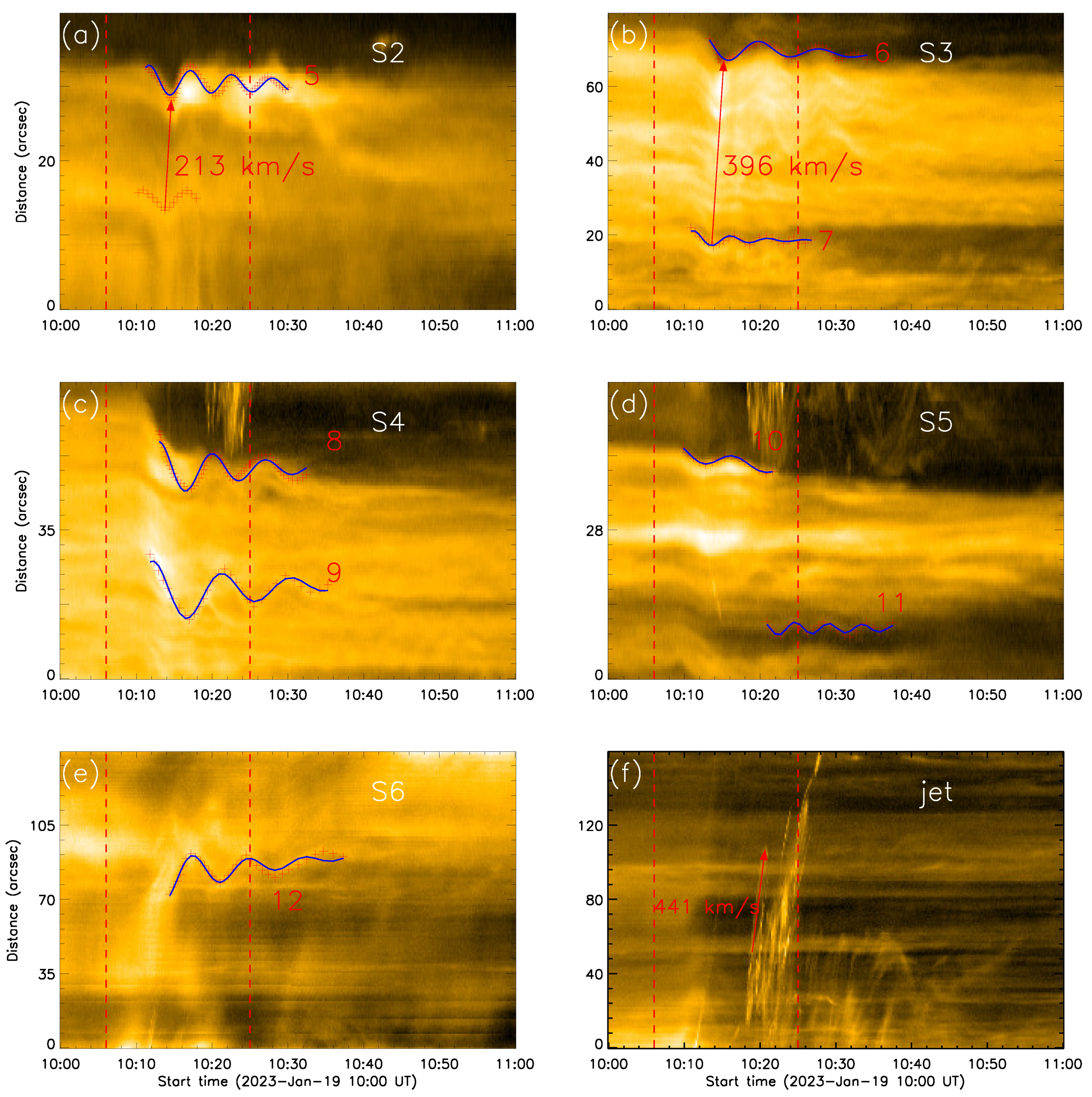
Figure 1b shows six slits at different positions of the coronal loop: S1–S5 are perpendicular, while S6 is parallel to the loop system, to facilitate the observation of the oscillation in the loop. Figure 3a–e show the time–distance maps of S2–S6. The red dashed lines represent the starts of two flares. The same as S1, it is clearly seen that many oscillations are overlapping and intersecting in slits S2–S5. We trace several oscillations that are located at the edges and are more pronounced in slits S1–S5. From Figure 3, it can be seen that these oscillations last for several periods and exhibit decaying kink oscillations. Due to the different lengths of the inner and outer loops, the oscillation of the inner loop begins before that of the outer loop. The red arrow in Figure 3 points from the trough of the inner loop oscillation to the trough of the outer loop oscillation. Its slope represents the speed at which the oscillation propagates from the inner loop to the outer loop. This also indicates that the phase of oscillations between different loops is not strictly the same, but there is a certain phase difference. Figure 3e shows a time–distance map along the loop marked by S6, in which a longitudinal oscillation parallel with the loop appears to be observed. Interestingly, we found that the oscillation in S6 has opposite phases from the other oscillations. At the beginning of the flare eruption, the coronal loop undergoes a severe contraction, causing strong disturbances in the middle loop. Figure 3e shows that the oscillation along S6 is similar as that along S1–S5. However, our observation does not show any relationship between them. Apart from this, there are no other obvious oscillation signals. Figure 3f shows the time–distance map along the direction of the jet, with the red arrow indicating the velocity of about 441 km/s. It is clear that all the loop oscillations are triggered by the first M1.7 flare. But, oscillation 11 seems to occur at the same time as the jet, which indicates the possibility that oscillation 11 is triggered by the jet. However, it is interesting that they are not affected by the second M1.0 flare eruption.

3. Data Analysis and Results

3.1. Position Oscillations in Coronal Loops

From the online animation, after the first M1.7 flare’s eruption, the coronal loop exhibits highly dynamic behavior, and the oscillations spread throughout the entire loop system. Figure 3 shows that the oscillations cross and overlap with each other due to a series of overlapping loop structures in the plots. In total, 12 individual oscillations were detected and marked by the numbers 1–12. We found that these oscillation behaviors basically have a decay trend, and some oscillations have obvious drifting motion along the slits. Therefore, we used a sine function with a decaying term and a linear trend to fit the loop oscillation [8,10,46], as shown in Equation (1):
A ( t ) = A m sin ( 2 π P ( t t 0 ) + ϕ ) · e t t 0 τ + k ( t t 0 ) + A 0 ,
where A m represents the initial displacement amplitude, P and ϕ represent the oscillation period and initial phase, τ represents the decay time, t 0 represents the start time of the oscillations, k ( t t 0 ) represents the drifting motion of the oscillation in the sky plane, where k represents its drifting velocity, and A 0 represents the initial position of the oscillation in the loop. These fitting parameters, as well as the duration of our measurements of 12 individual oscillations are listed in Table 1. The result fit by this function is plotted by the blue curves in Figure 2b and Figure 3a–e, which matches well with the manually identified oscillation. Previous studies of large-amplitude rapidly decaying kink oscillations have shown that both an exponential damping model and a generalized model (consisting of Gaussian and exponential damping patterns) fit observed damping profiles sufficiently well. However, it has recently been shown theoretically that the transition from the decaying regime to the decayless regime could be characterized by a superexponential damping model. Zhong et al. [47] studied ten oscillations and found that, in 7 out of 10 analyzed oscillations, the preferential damping model is the superexponential one. Our study is similar as the superexponential damping mode to study the decaying oscillations, but the latter describes the oscillations decay quickly. As noted earlier, the amplitudes are decreasing with time, and the velocity amplitude v m can be determined by taking the derivative of the displacement amplitude [45], while the velocity amplitude is projected on the plane of the sky. For example, v m = 2 π A m P as listed in Table 1 with an average of v m = 50 km/s for these 12 oscillations. The 12 individual oscillations have different oscillation periods. The fitting results show that they are oscillating almost in the same phase and with an average period of about 5.8 min. The period is between 3.08 and 9.10 min, which is a typical value of kink mode oscillation. Basically, the oscillation period of the outer loop is longer than that of the inner loop [48], which is also because the length of the outer loop is usually longer than that of the inner loop. The linear dependence of the oscillation period on the loop length allows one to estimate the kink wave speed, which for the fundamental harmonic is C k = 2 L / P . By changing the position of the kink velocity and period to obtain P = 2 L / C k , therefore, there are different periods for loops of different lengths, and their slopes remain unchanged, which is equivalent to having the same kink velocity in a loop system. In addition, due to the flare that triggers the transverse oscillation erupting near the southern footpoint of the coronal loop, the displacement amplitude of the oscillation near the southern footpoint (such as S4) is greater than that of the oscillation far away from the flare area (such as S1 and S2). But, from Figure 1b, it can be seen that slit S5 is located near the footpoint on the side of the flare, where the plasma is denser and the magnetic field is strong. The disturbance caused by the flare erupting in the loop near the footpoint is smaller. When the disturbance spreads to the area far away from the footpoint to the top of the loop, the loops are relatively loose and the disturbance is easily amplified.

3.2. DEM Analysis

From the observations, we further conducted differential emission measurement (DEM) analysis of the oscillation loop system. In this study, the improved sparse inversion code [49] developed by Su et al. [50] was applied to determine the DEM (T) distribution at each pixel, which was calculated from the SDO/AIA image data of six EUV passbands, namely AIA 94 Å, 131 Å, 171 Å, 193 Å, 211 Å, and 335 Å. Their uncertainty was estimated based on 100 Monte Carlo (MC) simulations of each pixel, i.e., 3 δ ( δ refers to the standard deviation of the 100 MC simulations).
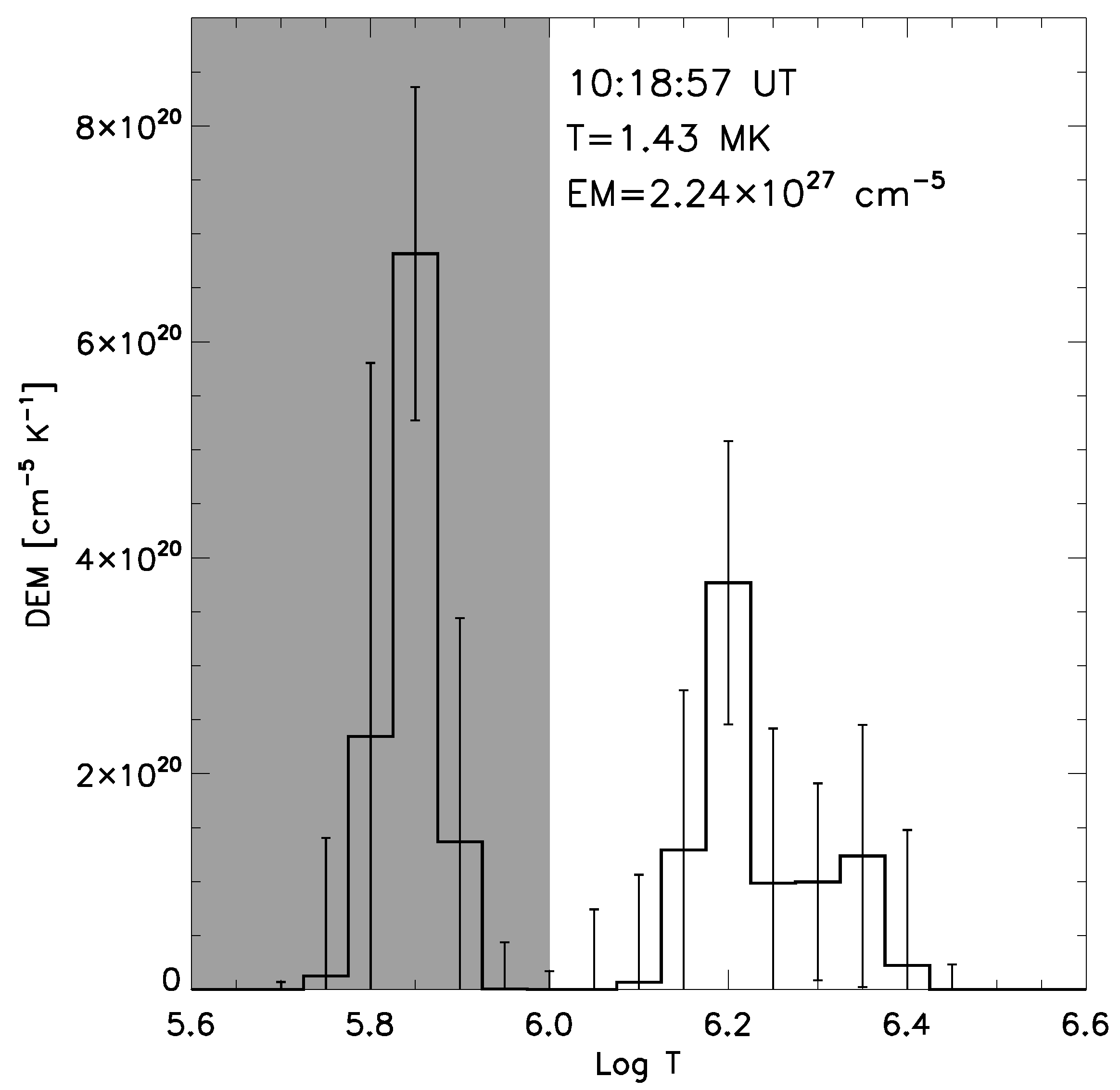
Figure 4 shows the DEM curves of the central position of slit S1, as shown in Figure 1c marked by the red point ‘p’ at 10:18:57 UT, the end time of the flare, with an error bar of double the standard deviation. This position is far from the flare region. It displays the temperature distribution of the DEM. It can be seen that there are two distinct peaks at log T = 5.9 (0.79 MK) corresponding to the temperature of the coronal loop in 171 Å and 6.2 (1.58 MK). We also give the average EM and T in Figure 4. The shaded area is the integral range of the temperature, as shown in Figure 5(a2), which corresponds to the temperature range, ranging from log T = 5.6 to 6.0 (from 0.3 MK to 1.0 MK).
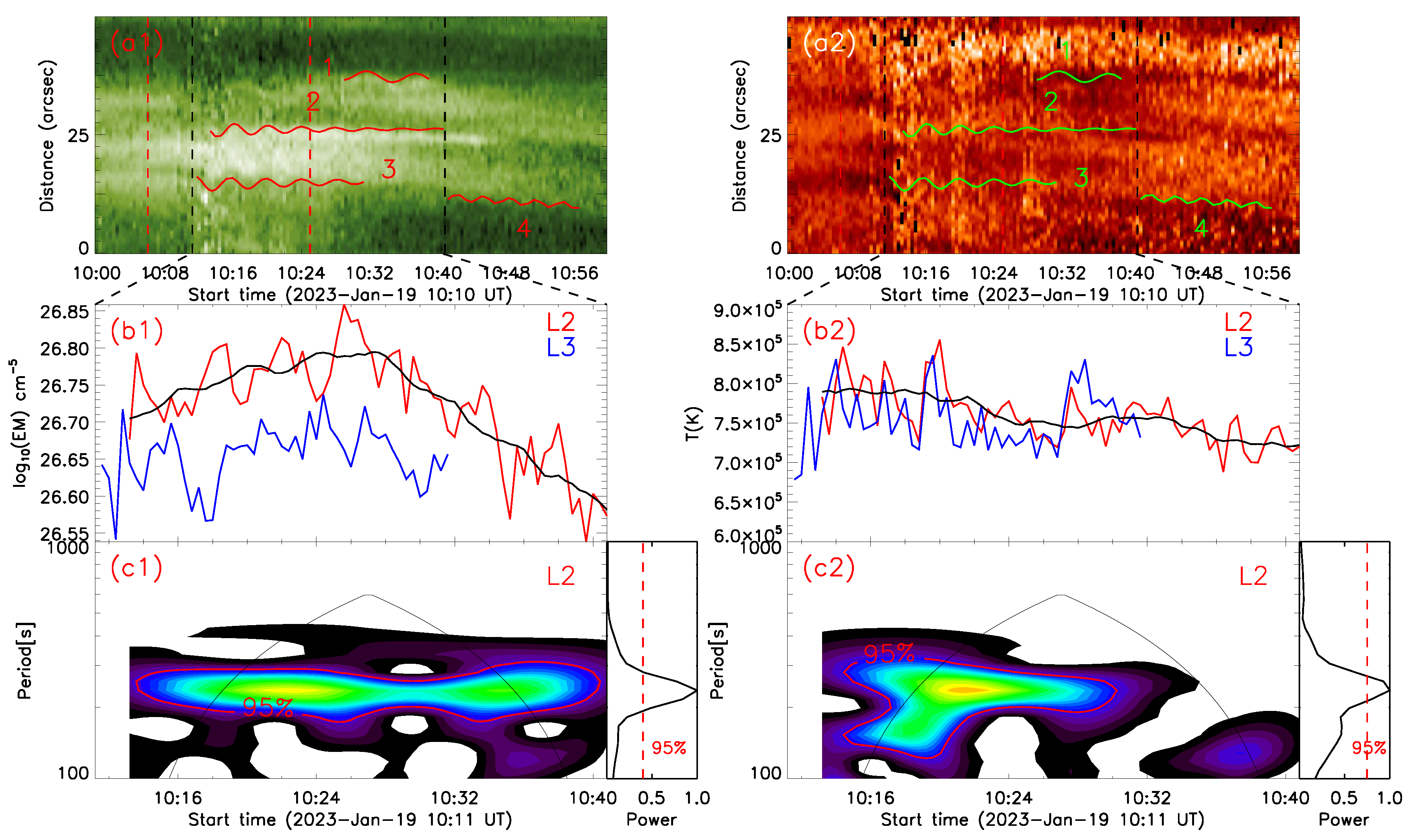
As shown in Figure 5(a1,a2), they are the time–distance maps of the emission measure (EM) and temperature (T) along slit S1, respectively. For the AIA passbands, the emission is optically thin. The EM presents the influence of both the column depth of the emitting volume, i.e., along the line-of-sight, and the plasma density. If the length of the loop system along the line-of-sight would be constant in time and space, then an EM map could present the distribution of the plasma density, with higher material density in a brighter EM and lower material density in a small EM. Similarly, in the temperature map, the bright areas have higher temperatures and the dark areas have lower temperatures. In the EM map, some oscillatory signals can be barely seen, namely the edges of high-density and low-density areas, as well as the center of brighter areas. We draw the fit oscillation trajectory from the time–distance map in Figure 2b on the EM map, as shown by the red line, and it can be observed that the oscillation trajectory is very similar to the change in material density in the loop, indicating that this decaying transverse oscillation is precisely caused by the displacement of the loops. The flare eruption injects hot and high-speed plasma from the footpoint into the coronal loop, which propagates along the coronal loop, causing a brief change in the material density and displacement in the loop. This also explains the phenomenon of the significant decay of these oscillations after a few periods. When the material eruption finishes, the coronal loop tends to stabilize, the material density does not change significantly, and the oscillation phenomenon disappears. In the temperature map, the oscillation trajectory is also drawn in the graph, as shown by the green line. It can be seen that the change in temperature is not as obvious as the oscillation. In the coronal loop, the temperature distribution is relatively uniform, and there is not much change overall.

3.3. Brightness Oscillations

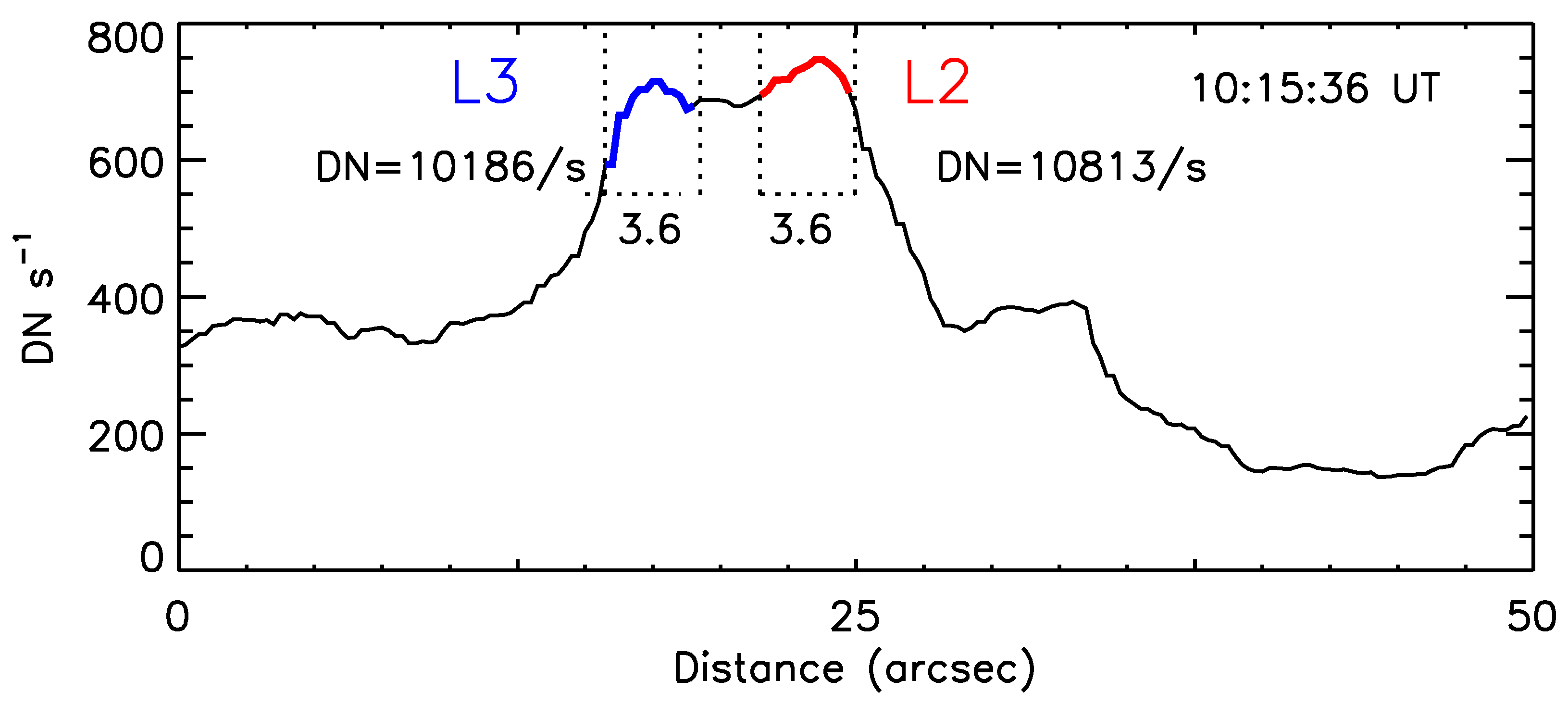
In Figure 2b, we notice that the loop brightness changes with time, as well as the position oscillation, especially for the oscillations 2, 3, and 4. Figure 2c gives the three light curves (red, blue, and brown) of their brightness at 171 Å. The brightness at each time is integrated in a region with a fixed width of 3.6 arcsec around the L2, L3, and L4 oscillating trajectories. Figure 5 gives an example of the brightness integration of L2 and L3 at 10:15:36 UT. The two peaks are the maximum brightness of L2 and L3 in Figure 2b. Two regions of dotted lines, as shown in Figure 6, represent the integration width, and the lines with red and blue color are the integrated brightness of L2 and L3 at 10:15:36 UT, respectively. The integration regions shift their positions with the L2 and L3 oscillations. Both L2 and L3 show their brightness oscillating, especially from 10:10 to 10:36 UT, which is the same as the intervals of loop position oscillations 2 and 3. In addition, it seems that there is no apparent change in the brightness of oscillation 4 in Figure 2b, but when we perform a light curve along the oscillation trajectory, we find that its brightness seems to have a certain periodicity, as shown in Figure 2c. Actually, except for the oscillation 2, 3, and 4, we do not find significant brightness oscillations in other individual position oscillations. In order to detect the L2 brightness oscillating period, we used the original brightness subtracted from the gradual component, as shown in Figure 2c by the black line, which is smoothed by 25 points. Then, we obtain the brightness oscillations of L2, as shown by the purple line from 10:10 to 10:36 UT. Figure 2d shows the global wavelet spectra, and the typical period is about 4 min, which is similar to that of the L2 position oscillation.
It is an interesting question how the brightness oscillation occurs. It is possibly due to the plasma density fluctuation or the temperature oscillations in the loops. Figure 5(b1,b2) show the integration curves along the oscillation trajectories 2 and 3. The width of the integration region is 3.6 arcsec. To better demonstrate the oscillation properties of the integration curve, the integration region of 2 is moved downwards three pixels along the oscillation center, and the integration region of 3 is moved upwards 1.8 arcsec along the oscillation center. The selected time range is from 10:11 UT to 10:40 UT. Oscillation 2 was selected for the analysis here, and the black curve represents its gradual component. After taking the logarithm of the vertical axis DEM, it can be seen that oscillation 2 has an oscillation in the EM as well. In the integral curve of the temperature in Figure 5(b2), it can be seen that the temperature changes between 6.5 × 10 5 K and 8.5 × 10 5 K, and we used the original brightness (red) subtracted from the gradual component (black), which is smoothed by 13 points. The result obtained is a clearer oscillation signal. Finally, oscillation 2 of the DEM and temperature curves was subjected to the wavelet transform to obtain the wavelet power spectra, as shown in Figure 5(c1,c2). A period of about four minutes can also be observed from them, which is similar to the period observed in Figure 2d and the fit period, confirming the relationship between the oscillation and changes in the material density.

4. Discussions and Conclusions

We studied the decaying transverse oscillation at different threads in the coronal loop using images captured by the SDO/AIA at 171 Åand also observed two flare eruptions occurring at the footpoint on the southern side of the coronal loop. The observed coronal loop oscillations are basically transverse, and most of them last for at least two periods, with the significant decay of the displacement amplitude. The initial displacement amplitude is basically 1–10 Mm and rapidly decays within a few periods, which is very similar to previous findings on coronal loop decaying oscillations [8,10,19,46]. The period and displacement amplitude of the oscillations also confirms that the transverse oscillations found in the coronal loop are decaying kink waves. A M1.7 flare was observed near the southern foot of the coronal loop. From the time–distance diagrams in Figure 3, it can be seen that the oscillation occurred a few minutes after the flare eruption, which also confirms that such a large solar flare induced the decaying and transverse oscillation of the coronal loop. This is also similar to previous observations, for example decaying oscillations are usually driven by solar activities such as solar flares, EUV waves, or coronal rain. But, actually, in the vast majority of detected cases, decaying kink oscillations are excited by the coronal eruptions behind these activities.
The observed decaying oscillation period in the coronal loop is between 3 and 9 min. Based on the fitting results of the oscillation trajectory, we found that oscillations 1 and 4 have decay times of 1027 min and 551 min, respectively. Compared to their oscillation periods of a few minutes, they can almost be considered as decayless oscillations. Moreover, both oscillations start later than the other oscillations and appear at the beginning and end of the second flare, respectively. At present, the mechanism of decayless oscillations is not clear, and we speculate that these two oscillations may be related to the eruption of the second flare. So, when calculating the ratio of the decay time to the oscillation period here, we only used data from oscillations with a significant decay, and the average ratio of the decaying time to the oscillation period was about 2.6, indicating that the decaying period was two or three oscillation periods. Generally speaking, the transverse oscillation of the entire coronal loop was considered as a kink mode wave. Based on the obtained oscillation period, assuming that the coronal loop where the oscillation was located was a semicircle, the distance between the two footpoints was measured. Using the half circumference formula of the circle, the loop length can be calculated to be about 122 Mm. Then, we can use Formulas (2)–(4) to diagnose the coronal seismology [48,51,52,53,54,55,56]:
c k = 2 L P
v A = c k · 1 + n e / n i 2
B c k 1 + ρ e / ρ i 2 μ 0 μ ˜ ρ i
Here, c k represents the kink speed and L and P represent the loop length and oscillation period. Here, we used the period of oscillation 2 in slit S1 to calculate c k = 1037 km/s. v A and B represent the Alfvén speed and magnetic field strength in the loop system, respectively. Assuming the ratio of the number density n e / n i = 0.1 [35], we can calculate the Alfvén speed v A = 769 km/s. μ 0 ( 4 π × 10 7 N A−2), and μ ˜ ( 1.27 ) represents the vacuum permeability and average molecular weight in the corona, respectively. ‘N’ is the force unit of Newtons, and ‘A’ is the current unit of Amperes in the International System of Units. Assuming an internal plasma density ρ i = 1.67 × 10 12 kg m−3 and the density contrast ( ρ e / ρ i ) to be equal to 1/3, the magnetic field in the coronal loop can be estimated to be about 13.8 G based on these data.
Much research has been conducted on the kink oscillation in the coronal loops, and many possible mechanisms have been proposed. Zimovets et al. [14] showed that the most probable mechanism for exciting the kink oscillations of coronal loops is the initial displacement of the loops from their equilibria by an eruption of some unstable plasma configuration, such as a flux rope or a system (arcade) of magnetic loops, or by a plasma ejection from a nearby flare site, rather than a blast shock wave excited by a flare. By using the DEM analysis, we found that the DEM displays a similar oscillating behavior, especially for position oscillations 2 and 3. This fact indicates that the thermal plasma is frozen in the loops and oscillates together with them. Interestingly, we found that the brightness of the loop exhibits oscillation similar to its position oscillation. The brightness oscillation has a period of 4.5 min, close to the period of the position oscillation of about 4.18 min. The DEM analysis shows that both the EM and temperature display the oscillations with a similar period. This finding suggests that the loop brightness oscillation could result from the plasma density and temperature fluctuation.
As noted earlier, the EM is assumed only to dependent on the plasma density, while the column depth along the line-of-sight (LOS) is stable. From our observation, we cannot rule out the effect of the column depth, which could affect the loop oscillation. Some studies suggest that the transverse oscillations found in the coronal loop are caused by the modulation of the emission intensity and the DEM by the variation of the column depth along the line-of-sight. Verwichte et al. [57] studied the transverse loop oscillation observed by STEREO and the Extreme Ultraviolet Imager (EUVI), and the plane of wave polarization was found from the comparison with a simulated loop model and showed that the oscillation is a fundamental horizontally polarized fast magnetoacoustic kink mode. They observed the clear intensity variations associated with the transverse loop oscillations, and they were shown to be caused by the effect of line-of-sight integration; the wave period they found was 10–11 min. White et al. [58] performed a detailed analysis including an analysis of the displacement time series and intensity variations and compared the EUVI and AIA data to estimate the 3D loop geometry. Time series analysis revealed periods between 1.7 and 10 min and damping times between 2.9 and 13 min. Cooper et al. [59] suggested that the kink modes of solar coronal structures, perturbing the loop in the direction along the line-of-sight (LOS), can be observed as emission intensity disturbances propagating along the loop provided the angle between the LOS and the structure is not ninety degrees. The effect is based on the change of the column depth of the loop (along the LOS) by the wave. It is an interesting direction to view disturbances in the coronal loop from the variation of the column depth along the line-of-sight, which can help us better understand the structure of oscillations in the coronal loop. More observational research is also needed to reveal the essence of the oscillations.

Author Contributions

Software, J.X., D.L. and F.S.; writing—original draft preparation, J.X.; writing—review and editing, J.X., Z.N., Y.S. and Y.Y. All authors have read and agreed to the published version of the manuscript.

Funding

This work is supported by the Strategic Priority Research Program of the Chinese Academy of Sciences, Grant No. XDB0560000. This work is also funded by the National Key R&D Program of China 2022YFF0503002 (2022YFF0503000) and the NSFC under grant 12073081.

Data Availability Statement

The data presented in this study are openly available on the homepage of SDO, GOES, and SUTRI.

Acknowledgments

We appreciate the teams of GOES, SDO, and SUTRI for their open data use policy.

Conflicts of Interest

The authors declare no conflicts of interest.

References

  1. Reale, F. Coronal loops: Observations and modeling of confined plasma. Living Rev. Sol. Phys. 2014, 11, 4. [Google Scholar] [CrossRef]
  2. Mac Cormack, C.; Fuentes, M.L.; Mandrini, C.; Lloveras, D.; Poisson, M.; Vásquez, A. Scaling Laws of Quiet-Sun Coronal Loops. arXiv 2022, arXiv:2206.09921. [Google Scholar] [CrossRef]
  3. Ji, H.; Cao, W.; Goode, P.R. Observation of ultrafine channels of solar corona heating. Astrophys. J. Lett. 2012, 750, L25. [Google Scholar] [CrossRef]
  4. Aschwanden, M.J.; Boerner, P. Solar corona loop studies with the atmospheric imaging assembly. I. Cross-sectional temperature structure. Astrophys. J. 2011, 732, 81. [Google Scholar] [CrossRef]
  5. Peter, H.; Bingert, S.; Klimchuk, J.; de Forest, C.; Cirtain, J.; Golub, L.; Winebarger, A.; Kobayashi, K.; Korreck, K. Structure of solar coronal loops: From miniature to large-scale. Astron. Astrophys. 2013, 556, A104. [Google Scholar] [CrossRef]
  6. Gupta, G.R.; Del Zanna, G.; Mason, H. Exploring the damping of Alfvén waves along a long off-limb coronal loop, up to 1.4 R⊙. Astron. Astrophys. 2019, 627, A62. [Google Scholar] [CrossRef]
  7. Nakariakov, V.M.; Kolotkov, D.Y. Magnetohydrodynamic waves in the solar corona. Annu. Rev. Astron. Astrophys. 2020, 58, 441–481. [Google Scholar] [CrossRef]
  8. Nakariakov, V.; Ofman, L.; Deluca, E.; Roberts, B.; Davila, J. TRACE observation of damped coronal loop oscillations: Implications for coronal heating. Science 1999, 285, 862–864. [Google Scholar] [CrossRef]
  9. Aschwanden, M.J.; De Pontieu, B.; Schrijver, C.J.; Title, A.M. Transverse oscillations in coronal loops observed with TRACE–II. Measurements of geometric and physical parameters. Sol. Phys. 2002, 206, 99–132. [Google Scholar] [CrossRef]
  10. Goddard, C.; Nisticò, G.; Nakariakov, V.; Zimovets, I. A statistical study of decaying kink oscillations detected using SDO/AIA. Astron. Astrophys. 2016, 585, A137. [Google Scholar] [CrossRef]
  11. Anfinogentov, S.; Nakariakov, V.; Nisticò, G. Decayless low-amplitude kink oscillations: A common phenomenon in the solar corona? Astron. Astrophys. 2015, 583, A136. [Google Scholar] [CrossRef]
  12. Karampelas, K.; Van Doorsselaere, T. Transverse loop oscillations via vortex shedding: A self-oscillating process. Astrophys. J. Lett. 2021, 908, L7. [Google Scholar] [CrossRef]
  13. Mandal, S.; Chitta, L.P.; Antolin, P.; Peter, H.; Solanki, S.K.; Auchère, F.; Berghmans, D.; Zhukov, A.N.; Teriaca, L.; Cuadrado, R.A.; et al. What drives decayless kink oscillations in active-region coronal loops on the Sun? Astron. Astrophys. 2022, 666, L2. [Google Scholar] [CrossRef]
  14. Zimovets, I.; Nakariakov, V. Excitation of kink oscillations of coronal loops: Statistical study. Astron. Astrophys. 2015, 577, A4. [Google Scholar] [CrossRef]
  15. Shen, Y.; Liu, Y.; Tian, Z.; Qu, Z. On a small-scale EUV wave: The driving mechanism and the associated oscillating filament. Astrophys. J. 2017, 851, 101. [Google Scholar] [CrossRef]
  16. Shen, Y.; Tang, Z.; Li, H.; Liu, Y. Coronal EUV, QFP, and kink waves simultaneously launched during the course of jet–loop interaction. Mon. Not. R. Astron. Soc. Lett. 2018, 480, L63–L67. [Google Scholar] [CrossRef]
  17. Reeves, K.K.; Polito, V.; Chen, B.; Galan, G.; Yu, S.; Liu, W.; Li, G. Hot plasma flows and oscillations in the loop-top region during the 2017 September 10 X8. 2 solar flare. Astrophys. J. 2020, 905, 165. [Google Scholar] [CrossRef]
  18. Zhang, Q. Simultaneous transverse oscillations of a coronal loop and a filament excited by a circular-ribbon flare. Astron. Astrophys. 2020, 642, A159. [Google Scholar] [CrossRef]
  19. Nechaeva, A.; Zimovets, I.V.; Nakariakov, V.M.; Goddard, C. Catalog of decaying kink oscillations of coronal loops in the 24th solar cycle. Astrophys. J. Suppl. Ser. 2019, 241, 31. [Google Scholar] [CrossRef]
  20. Hui, T.; McIntosh, S.W.; Wang, T.; Ofman, L.; De Pontieu, B.; Innes, D.E.; Peter, H. Persistent doppler shift oscillations observed with Hinode/EIS in the solar corona: Spectroscopic signatures of Alfvenic waves and recurring upflows. Astrophys. J. 2012, 759, 144. [Google Scholar]
  21. Nakariakov, V.M.; Anfinogentov, S.; Nisticò, G.; Lee, D.H. Undamped transverse oscillations of coronal loops as a self-oscillatory process. Astron. Astrophys. 2016, 591, L5. [Google Scholar] [CrossRef]
  22. Guo, X.; Liang, B.; Feng, S.; Dai, W.; Yang, Y. Simultaneous Detection of Flare-related Decaying and Decayless Kink Oscillations Using Jerk-aware Motion Magnification. Res. Astron. Astrophys. 2022, 22, 115012. [Google Scholar] [CrossRef]
  23. Pascoe, D.J.; Goddard, C.R.; Nakariakov, V.M. Spatially resolved observation of the fundamental and second harmonic standing kink modes using SDO/AIA. Astron. Astrophys. 2016, 593, A53. [Google Scholar] [CrossRef]
  24. Mandal, S.; Tian, H.; Peter, H. Flare-induced decay-less transverse oscillations in solar coronal loops. Astron. Astrophys. 2021, 652, L3. [Google Scholar] [CrossRef]
  25. Zhong, S.; Nakariakov, V.M.; Kolotkov, D.Y.; Verbeeck, C.; Berghmans, D. Two-spacecraft detection of short-period decayless kink oscillations of solar coronal loops. Mon. Not. R. Astron. Soc. 2022, 516, 5989–5996. [Google Scholar] [CrossRef]
  26. Hindman, B.W.; Jain, R. An interpretation of flare-induced and decayless coronal-loop oscillations as interference patterns. Astrophys. J. 2014, 784, 103. [Google Scholar] [CrossRef]
  27. Antolin, P.; De Moortel, I.; Van Doorsselaere, T.; Yokoyama, T. Modeling observed decay-less oscillations as resonantly enhanced Kelvin–Helmholtz vortices from transverse MHD waves and their seismological application. Astrophys. J. Lett. 2016, 830, L22. [Google Scholar] [CrossRef]
  28. Karampelas, K.; Van Doorsselaere, T.; Antolin, P. Heating by transverse waves in simulated coronal loops. Astron. Astrophys. 2017, 604, A130. [Google Scholar] [CrossRef]
  29. Karampelas, K.; Van Doorsselaere, T. Generating transverse loop oscillations through a steady-flow driver. Astrophys. J. Lett. 2020, 897, L35. [Google Scholar] [CrossRef]
  30. Afanasyev, A.; Van Doorsselaere, T.; Nakariakov, V. Excitation of decay-less transverse oscillations of coronal loops by random motions. Astron. Astrophys. 2020, 633, L8. [Google Scholar] [CrossRef]
  31. Ruderman, M.; Petrukhin, N. Excitation of decayless kink oscillations by random motion. Mon. Not. R. Astron. Soc. 2021, 501, 3017–3029. [Google Scholar] [CrossRef]
  32. Goossens, M.; Van Doorsselaere, T.; Soler, R.; Verth, G. Energy content and propagation in transverse solar atmospheric waves. Astrophys. J. 2013, 768, 191, Erratum in Astrophys. J. 2013, 771, 74. [Google Scholar] [CrossRef]
  33. Zaitsev, V.V.; Stepanov, A.V. Coronal magnetic loops. Physics-Uspekhi 2008, 51, 1123. [Google Scholar] [CrossRef]
  34. Stepanov, A.V.; Zaitsev, V.V.; Nakariakov, V.M. Coronal seismology. Physics-Uspekhi 2012, 55, 929. [Google Scholar] [CrossRef]
  35. Nakariakov, V.M.; Ofman, L. Determination of the coronal magnetic field by coronal loop oscillations. Astron. Astrophys. 2001, 372, L53–L56. [Google Scholar] [CrossRef]
  36. Andries, J.; Arregui, I.; Goossens, M. Determination of the coronal density stratification from the observation of harmonic coronal loop oscillations. Astrophys. J. 2005, 624, L57. [Google Scholar] [CrossRef]
  37. Van Doorsselaere, T.; Brady, C.S.; Verwichte, E.; Nakariakov, V.M. Seismological demonstration of perpendicular density structuring in the solar corona. Astron. Astrophys. 2008, 491, L9–L12. [Google Scholar] [CrossRef]
  38. Ruderman, M.S.; Verth, G.; Erdélyi, R. Transverse oscillations of longitudinally stratified coronal loops with variable cross section. Astrophys. J. 2008, 686, 694. [Google Scholar] [CrossRef]
  39. Verth, G.; Erdélyi, R. Effect of longitudinal magnetic and density inhomogeneity on transversal coronal loop oscillations. Astron. Astrophys. 2008, 486, 1015–1022. [Google Scholar] [CrossRef]
  40. Antolin, P.; Yokoyama, T.; Van Doorsselaere, T. Fine strand-like structure in the solar corona from magnetohydrodynamic transverse oscillations. Astrophys. J. Lett. 2014, 787, L22. [Google Scholar] [CrossRef]
  41. Pesnell, W.D.; Thompson, B.J.; Chamberlin, P. The Solar Dynamics Observatory (SDO); Springer: Berlin/Heidelberg, Germany, 2012. [Google Scholar]
  42. Boerner, P.; Edwards, C.; Lemen, J.; Rausch, A.; Schrijver, C.; Shine, R.; Shing, L.; Stern, R.; Tarbell, T.; Title, A.; et al. Initial calibration of the atmospheric imaging assembly (AIA) on the solar dynamics observatory (SDO). Sol. Phys. 2012, 275, 41–66. [Google Scholar] [CrossRef]
  43. Lemen, J.R.; Title, A.M.; Akin, D.J.; Boerner, P.F.; Chou, C.; Drake, J.F.; Duncan, D.W.; Edwards, C.G.; Friedlaender, F.M.; Heyman, G.F.; et al. The atmospheric imaging assembly (AIA) on the solar dynamics observatory (SDO). Sol. Phys. 2012, 275, 17–40. [Google Scholar] [CrossRef]
  44. Wang, T.; Ofman, L.; Davila, J.M.; Su, Y. Growing transverse oscillations of a multistranded loop observed by SDO/AIA. Astrophys. J. Lett. 2012, 751, L27. [Google Scholar] [CrossRef]
  45. Gao, Y.; Tian, H.; Van Doorsselaere, T.; Chen, Y. Decayless oscillations in solar coronal bright points. Astrophys. J. 2022, 930, 55. [Google Scholar] [CrossRef]
  46. Su, W.; Guo, Y.; Erdélyi, R.; Ning, Z.; Ding, M.; Cheng, X.; Tan, B. Period increase and amplitude distribution of kink oscillation of coronal loop. Sci. Rep. 2018, 8, 4471. [Google Scholar] [CrossRef]
  47. Zhong, Y.; Kolotkov, D.Y.; Zhong, S.; Nakariakov, V.M. Comparison of damping models for kink oscillations of coronal loops. Mon. Not. R. Astron. Soc. 2023, 525, 5033–5040. [Google Scholar] [CrossRef]
  48. Nakariakov, V.; Anfinogentov, S.; Antolin, P.; Jain, R.; Kolotkov, D.; Kupriyanova, E.; Li, D.; Magyar, N.; Nistico, G.; Pascoe, D.; et al. Kink oscillations of coronal loops. Space Sci. Rev. 2021, 217, 73. [Google Scholar] [CrossRef]
  49. Cheung, M.C.; Boerner, P.; Schrijver, C.; Testa, P.; Chen, F.; Peter, H.; Malanushenko, A. Thermal diagnostics with the atmospheric imaging assembly on board the solar dynamics observatory: A validated method for differential emission measure inversions. Astrophys. J. 2015, 807, 143. [Google Scholar] [CrossRef]
  50. Su, Y.; Veronig, A.M.; Hannah, I.G.; Cheung, M.C.; Dennis, B.R.; Holman, G.D.; Gan, W.; Li, Y. Determination of differential emission measure from solar extreme ultraviolet images. Astrophys. J. Lett. 2018, 856, L17. [Google Scholar] [CrossRef]
  51. Van Doorsselaere, T.; Gijsen, S.; Andries, J.; Verth, G. Energy propagation by transverse waves in multiple flux tube systems using filling factors. Astrophys. J. 2014, 795, 18. [Google Scholar] [CrossRef]
  52. Yuan, D.; Van Doorsselaere, T. Forward modeling of standing kink modes in coronal loops. I. Synthetic views. Astrophys. J. Suppl. Ser. 2016, 223, 23. [Google Scholar] [CrossRef]
  53. Long, D.M.; Valori, G.; Pérez-Suárez, D.; Morton, R.J.; Vásquez, A.M. Measuring the magnetic field of a trans-equatorial loop system using coronal seismology. Astron. Astrophys. 2017, 603, A101. [Google Scholar] [CrossRef]
  54. Yang, Z.; Tian, H.; Tomczyk, S.; Morton, R.; Bai, X.; Samanta, T.; Chen, Y. Mapping the magnetic field in the solar corona through magnetoseismology. Sci. China Technol. Sci. 2020, 63, 2357–2368. [Google Scholar] [CrossRef]
  55. Li, D.; Bai, X.; Tian, H.; Su, J.; Hou, Z.; Deng, Y.; Ji, K.; Ning, Z. Traveling kink oscillations of coronal loops launched by a solar flare. Astron. Astrophys. 2023, 675, A169. [Google Scholar] [CrossRef]
  56. Li, D.; Long, D.M. A Statistical Study of Short-period Decayless Oscillations of Coronal Loops in an Active Region. Astron. Astrophys. 2023, 944, 8. [Google Scholar] [CrossRef]
  57. Verwichte, E.; Aschwanden, M.J.; Van Doorsselaere, T.; Foullon, C.; Nakariakov, V.M. Seismology of a Large Solar Coronal Loop from EUVI/STEREO Observations of its Transverse Oscillation. Astron. Astrophys. 2009, 698, 397–404. [Google Scholar] [CrossRef]
  58. White, R.S.; Verwichte, E. Transverse coronal loop oscillations seen in unprecedented detail by AIA/SDO. Astron. Astrophys. 2012, 537, A49. [Google Scholar] [CrossRef]
  59. Cooper, F.C.; Nakariakov, V.M.; Tsiklauri, D. Line-of-sight effects on observability of kink and sausage modes in coronal structures with imaging telescopes. Astron. Astrophys. 2003, 397, 765–770. [Google Scholar] [CrossRef]
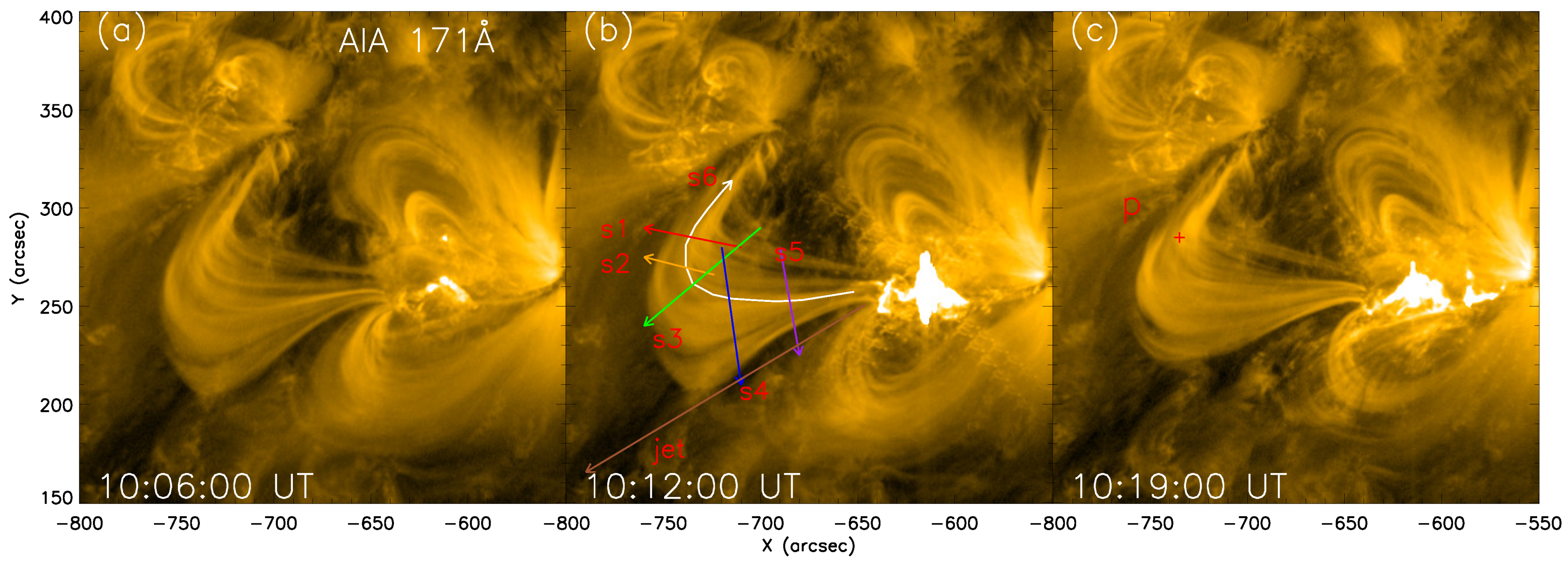
Figure 1. (ac) Flare images at AIA 171 Å. Corresponding to the start, peak, and end of the first flare, respectively.
Universe 10 00201 g001
Figure 2. (a) The GOES soft X-ray flux between 10:00 UT and 11:00 UT. (b) The time–distance map of slit S1. The red dashed lines represent the start times of the two flares. The red arrow points from the inner loop to the outer loop, and the four oscillations are determined and fit by manually selecting points. (c) The light curves along three oscillations L2 (red), L3 (blue), and L4 (brown, multiplied by 2.5), with a time range of 10:11 to 10:40 UT. The black curve represents the smooth component of L2, and the purple curve represents the result obtained by subtracting the smoothed component from the original light curve of L2. (d) The global wavelet spectrum of the purple curve.
Universe 10 00201 g002
Figure 3. (af) Time–distance map of slits S2 to S6 and the jet; the vertical red dotted line labels the onset of the flare. The red plus sign is manually obtained along the oscillation edge position, and the blue curve is a sine fitting of the oscillation; their key parameters are listed in Table 1. The red arrow represents the oscillation propagating outward along the inner loop, and its slope represents the speed of propagation.
Universe 10 00201 g003
Figure 4. The DEM curves of the central position of slit S1 as shown in Figure 1c marked by the red point ‘p’ at 10:18:57 UT, the end time of the flare. The error bars have twice the standard deviation, and the average EM and T are shown in the graph. The shaded area is the integration range for the temperature, from log (T) = 5.6 to 6.0.
Universe 10 00201 g004
Figure 5. (a1,a2) Time–distance maps of the EM and temperature T. The vertical red dashed lines represent the start times of the two flare eruptions, and the red and green lines represent the fit oscillation trajectory. (b1,b2) represent the integration curves along oscillation trajectories 2 and 3, while the black curve represents the gradual component in the time range of 10:11 UT to 10:40 UT. (c1,c2) The power spectrum obtained by the wavelet transform from the rapidly varying component of oscillation curve L2.
Universe 10 00201 g005
Figure 6. Intensity along slit S1 at 10:15:36 UT. The two peaks are the maximum brightness of L2 and L3 in Figure 2b. The lines with red and blue color represent the integration width of 3.6 arcsec to obtain the total intensity (in Figure 2c) at 10:15:36 UT.
Universe 10 00201 g006
Table 1. Key parameters (period, initial displacement amplitude, decay time, velocity amplitude, initial phase, and duration) measured in the oscillating loops at six slits.
SlitLoopsP (min) A m (Mm) τ (min) v m (km/s) ϕ (min)Duration (min)
S115.790.841027.7015.171.629.91
23.931.3011.9834.651.9527.33
34.181.3315.6133.300.8719.55
43.080.58551.0919.651.1314.49
S255.431.5619.3730.161.4518.82
S368.033.2010.5541.701.7920.82
74.911.946.3141.501.0415.89
S487.045.3411.8579.441.5619.42
99.106.6513.6276.492.2623.47
S5107.911.2120.1916.081.7611.77
114.431.0621.9625.050.7416.62
S6127.418.7910.50124.291.4722.94
Disclaimer/Publisher’s Note: The statements, opinions and data contained in all publications are solely those of the individual author(s) and contributor(s) and not of MDPI and/or the editor(s). MDPI and/or the editor(s) disclaim responsibility for any injury to people or property resulting from any ideas, methods, instructions or products referred to in the content.