Article

Cyber Attacks on Precision Time Protocol Networks—A Case Study

School of Computer Science, National University of Ireland, H91 TK33 Galway, Ireland
*
Author to whom correspondence should be addressed.
Electronics 2020, 9(9), 1398; https://doi.org/10.3390/electronics9091398
Submission received: 24 July 2020 / Revised: 21 August 2020 / Accepted: 24 August 2020 / Published: 28 August 2020
(This article belongs to the Section Networks)

Abstract

:
The IEEE 1588 precision time protocol (PTP) is used by many time-sensitive applications and systems, as it achieves sub-microsecond time synchronization between computer clocks. However, a PTP network is vulnerable to cyber-attacks that can reduce the protocol accuracy to unacceptable levels for some or all clocks in a network with potentially devastating consequences. Of particular concern are advanced persistent threats (APT), where an actor infiltrates a network and operates stealthily and over extended periods of time before being discovered. This paper investigates the impact of the most important APT strategies on a PTP network, i.e., the delay attack, packet modification or transparent clock attack, and time reference attack, using a fully programable and customizable man in the middle device, thereby considering the two most popular PTP slave daemons PTPd and PTP4l. In doing so, it determines suitable attack patterns and parameters to compromise the time synchronization covertly.

1. Introduction

The precision time protocol (PTP) has importance for time-sensitive domains such as telecommunications, financial services, and industrial control. It is deployed in infrastructure networks, i.e., well-managed packet switch networks (PSNs) that often use dedicated (PTP-aware) hardware, thereby providing computer clock synchronization accuracy down to microsecond and even nanosecond level [1]. This accuracy is required by many financial markets and leading exchanges such as Eurex, The New York Stock Exchange (NYSE), and International Marketmakers Combination (IMC) that allow PTP time synchronization from their systems with market client/participants, so that they can synchronize their clocks with the exchange [2].
PTP is vulnerable to cyberattacks, which cause a significant hazard to many time-sensitive application areas [3]. Advanced persistent threats (APTs) [4], similar to the Stuxnet attack of 2010 on industrial control systems [5], are of particular concern. Stuxnet’s apparent target was the Natanz uranium enrichment facility, and it stealthily spread there across programmable logical controller (PLC) and supervisory control and data acquisition (SCADA) systems, subsequently compromising the operation of this facility for many months before its discovery. Stuxnet did not require an Internet connection to reach its target; instead, it entered the facility via a removable flash drive brought in by an employee [6]. A Stuxnet-like attack on a time synchronization network could similarly target PTP infrastructure components, slowly interfere with the clock synchronization of endpoints, therefore stealthily undermine proper system and application operation, like for example manipulating the timestamps of high-frequency trading transactions.
The first version of PTP did not provide a security extension, and as a result, there have been various approaches over the last decade to combine it with security protocol extensions or infrastructure enhancements. This includes the experimental security extension Annex K (introduced with the IEEE 1588 version 2) in 2008, which has been proven to be insufficient [7,8]. PTP version 2.1 (IEEE 1588-2019) [9], was recently released in 2020; it includes a new security extension called Annex P. Annex P consist of four prongs as follows [10]:
  • Prong A (integrated security mechanism) specifies an authentication type-length-value (TLV) to protect PTP messages using a symmetric key. More details of implementing Prong A on power profile using PTP daemon (PTPd) can be found in [11];
  • Prong B (PTP external transport security mechanisms) describes external security extensions, i.e., Media Access Control Security (MACsec) and IP Security (IPsec) that can be used to protect the PTP messages;
  • Prong C (architecture guidance) describes various redundancy approaches, i.e., redundant time system, redundant grandmaster, and redundant paths;
  • Prong D (monitoring and management guidance) describes a monitoring system to observe the PTP slave behavior.
However, it has been shown that state-of-the-art cryptographic security protocols (i.e., Prong A and Prong B) can only deter a subset of potential attacks [3], while Prong C (i.e., multiple paths, redundant grandmaster and protocol redundancy) do not provide a provable secure way to prevent an attacker from exploiting PTP vulnerabilities either [12].
An in-depth analysis of potential APT attack strategies on PTP networks, including attacker types (i.e., man in the middle or injector), their location within a network, their impact on clock synchronization (i.e., clock manipulation, versus clock free-running), and the impact range (i.e., affecting all slaves, a subset of slaves or a single slave) in the presence of protocol security extensions and infrastructure redundancy including Annex P was presented in [12], therefore extending prior research conducted by [3,8]. This paper will build on these findings and present the results of the experimental proof-of-concept implementations of the most far-reaching APT attacks identified, therefore making the following contributions: (1) an analysis of the time correction algorithms (and their characteristics/weaknesses) implemented in two popular PTP daemons (i.e., PTP4l and PTPd), (2) prototyping of a PTP hardware “sandbox” testbed that is able to perform various of man in the middle (MitM) attacks, namely delay, time source, and packet modification attacks, (3) determining suitable attack patterns and parameters, and (4) analyzing the effect of such attacks on slave clock synchronization, operation and behavior. The MitM implementation goes beyond existing research in [13,14,15], as this paper simulates the APT behavior using a hardware-based programmable MitM that can manipulate PTP packets and change the attack parameters dynamically over time. In doing so, it determines suitable attack patterns and parameters to compromise the time synchronization covertly.
The rest of this paper is structured as follows: Section 2 provides an overview of PTP, PTP software daemons, and a summary of security concerns. Section 3 describes an experimental testbed based on different PTP devices (i.e., slaves, switches, grandmaster—GM and transparent clock—TC), presents the MitM device, and characterizes different slave clocks. The experimental result of packet propagation attacks (i.e., delay and transparent clock attacks), and time reference attack will be shown in Section 4, followed by the outline of a proposed attack detection system in Section 5 and conclusions and future work in Section 6.

2. The Precision Time Protocol and Security Concerns
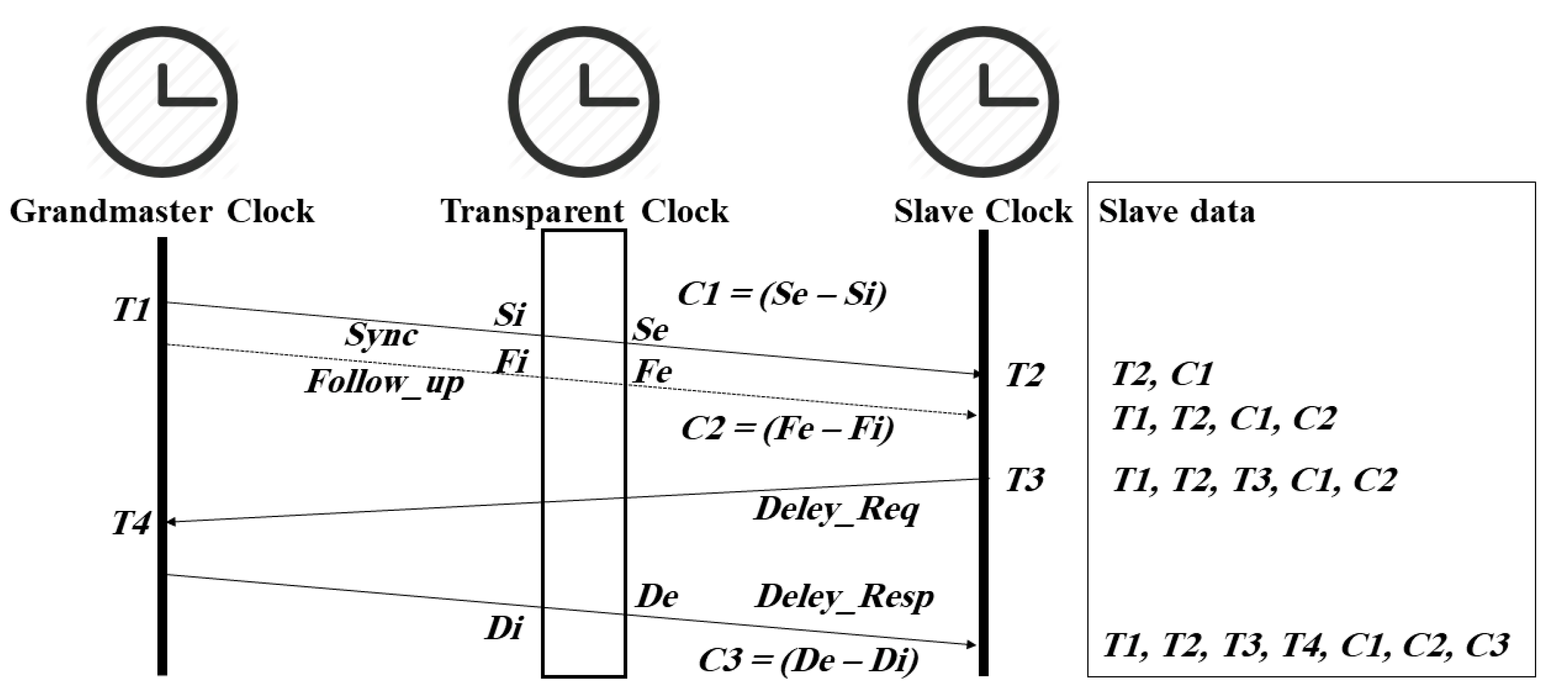
2.1. PTP Overview

IEEE 1588 (PTP) is a protocol used to synchronize a clock or group of clocks (slaves) to the most accurate clock in a network (grandmaster—GM). It can achieve sub-microsecond time synchronization between these clocks. A PTP network may contain different PTP entities (i.e., a single grandmaster clock, slave clock(s), boundary clock(s), and transparent clock(s)) beside the ordinary network infrastructure that includes switches or/and routers. The grandmaster clock and slave clocks are ordinary clocks with different clock attributes. These attributes are used by the best master clock algorithm (BMCA) to determine which clock makes the most suitable grandmaster (i.e., the best clock in the network), forcing the other clocks to go into slave mode or a passive state. The grandmaster clock provides the (root) time reference for all other clocks. Boundary clocks (BC) and transparent clocks (TC) have multiple ports, and they deal with PTP messages in different ways. All boundary clock ports will act as a master to other slaves connected to them, except for one port that will act as a slave to the grandmaster or another master port of a different boundary clock. In contrast, a transparent clock computes the residence time of certain types of PTP messages and adds this value to the correctionField in the PTP message, allowing for a more accurate estimation of uplink and downlink delays. PTP provides two different delay mechanisms (end-to-end and peer-to-peer) and two different mode operations (one-step and two-step). This paper will focus on the end-to-end delay mechanism and the two-step mode operation. More details on PTP and its different delay mechanisms can be found in [1].
In the end-to-end delay mechanism there are four timestamps required to calculate the offset (the time difference between a slave and the master) in slave clocks. They are exchanged between the master and slaves as shown in Figure 1 [7]: a slave measures T2 and T3 itself, while receiving timestamps T1 and T4 as packet payloads sent by the master clock. In addition, if a TC is located between the master and a slave, the TC timestamps the Sync (S), Follow_Up (F) and Delay_Resp (D) messages on ingress (i.e., Si, Fi and Di) and egress (i.e., Se, Fe and De), and computes the time taken (C1, C2 and C3) for these messages to traverse the node by subtracting the egress and ingress values [16]. PTP clock synchronization assumes that the network delay between slaves and their master is symmetric. So, the offset and mean path delay (the average of time taken for a PTP message to traverse from a master to slave and vice versa) are computed as shown in Equations (1) and (2):
offset = ((T2 − T1 − C1 − C2) − (T4 − T3 − C3))/2
meanPathDelay = ((T2 − T1 − C1 − C2) + (T4 − T3 − C3))/2
where C1 = Se − Si, C2 = Fe − Fi and C3 = De − Di.
Finally, the PTP uses the calculated offset to update the slave clock. In addition, PTP provides a method to syntonize a clock (e.g., a TC) to the grandmaster clock, where its clock frequency follows the grandmaster clock frequency, by introducing a dynamic clock correction factor, which is subsequently multiplied with local timestamps. It is calculated as follows [1]:
correction factor = ((T2)n − (T2)0)/((T1+ meanPathDelay + C1 + C2)n − (T1 + meanPathDelay + C1 + C2)0)
with n (n > 0) is the number of sync intervals separating the timestamps, e.g., (T2)n versus (T2)0.

2.2. Existing PTP Software Daemons

There are many PTP implementations that work on different platforms [17]. This paper will focus on two popular open-source PTP slave software implementations, namely linuxptp (also called PTP4l) and PTPd. PTP4l is a Linux client [18], whereas PTPd is available for Linux, FreeBSD and Mac OS X [19]. While both implementations follow the message sequence as shown in Figure 1, in practice the GM and the slave clocks send out Sync/Follow_Up and Delay_Req messages independently from each other at configurable rates, i.e., the transmission of a Delay_Req message is not triggered by the reception of a Follow_Up message. The delay request measurements are only done on a best effort basis and may not be executed in a timely manner.

2.2.1. PTP Daemon (PTPd)—Version 2.3.2

PTPd [20] records the time arrival of each Sync message (T2) as well as the content of its correctionField (C1). It then extracts the preciseOriginTimestamp field value (T1) and the correctionField value (C2) of the corresponding Follow_Up message (that matches the sequenceID of the Sync message). After that, the daemon calculates the delay between the master and the slave:
MSdelay = T2 − T1 − (C1 + C2)
The daemon then records the departure time of a Delay_Req message (T3), and eventually receives the corresponding Delay_Resp message (with identical sequenceID). It extracts the receiveTimestamp field value (T4) and the correctionField value (C3) of this message. The software now calculates the delay between slave and master:
SMdelay = T4 − T3
and the mean path delay via
meanPathDelay = ((MSdelay + SMdelay) − C3)/2
If the meanPathDelay value is greater than one second or a negative value, it is replaced by the last valid delay value, before the offset is calculated:
offsetFromMaster = MSdelay − meanPathDelay
Finally, PTPd calculates the average of this offset and the previous offset, before updating the system clock. The overall offset equation (without averaging) is as follows:
Offset = (T2 − T1 − (C1 + C2)) − (((T2 − T1 − (C1 + C2)) + (T4 − T3)) − C3)/2
More details on PTPd can be found in [21].

2.2.2. Linuxptp (PTP4l) Version (2.0)

PTP4l [22] records the arrival time of the Sync message (T2), extracts its correctionField value (C1), waits for the arrival of the corresponding Follow_Up message (with identical sequenceID) and extracts the preciseOriginTimestamp (T1) as well as the correctionField value (C2). It records the transmission time (T3) of a Delay_Req message and extracts its arrival (T4) and its correctionField (C3) from the corresponding Delay_Resp message. PTP4l has provisions for calculating the time difference (delayAsymmetry) between the transmitting and receiving path (which is positive when the master-to-slave propagation time is longer and negative when the slave-to-master time is longer). However, a default value of zero is hard-coded into the software. PTP4l computes the ratio and frequency deviation of the local clock in relation to the master clock by using the last two values of T2 and two corrected values of T1 (including the path delay), as follows:
ratio = (T2n − T2n−1)/(T1n − T1n−1)
frequency = (1.0 − ratio) * 109
The final offset and delay equations are as follows:
Offset = (T2 − (T1+C1+ delayAsymmetry +C2)) − ((T2 − T3) * frequency + (T4 − C3 − (T1 + C1 +
delayAsymmetry + C2)))/2
meanPathDelay = (((T2 − T3) * ratio) + ((T4 − C3) − (T1 + C1 + C2))) 2
It is worth noting that for both daemons the above methodologies/algorithms did not change between recent software versions.

2.3. Slave Clock Adjustment

Both PTP daemons use the calculated offset to update the slave clock by either resetting the clock, i.e., step the clock, or gradually adjusting the clock, i.e., add a small amount of time to the clock every second and/or change the clock frequency, using the following configuration options:
  • Disable/enable PTP clock adjustment: if the clock adjustment is disabled, the clock will be in free-running mode. If enabled, both daemons use the time offset to calculate the frequency offset between the slave and its master, and gradually adjust the local clock tick duration to improve the local slave clock accuracy. Furthermore, PTPd updates the slave time by adding a small percentage of time to the slave clock depending on the calculated offset.
  • Maximum clock frequency adjustment: this is an upper threshold for the maximal permissible (positive or negative) frequency correction as calculated above.
  • Disable/enable clock reset: if disabled, local clock adjustments per synchronization cycle are limited to the above value. If enabled, the daemon resets the clock when synchronization starts and/or when a calculated offset is larger than a configurable threshold. Resetting the clock makes the slave time the same as the master time in one synchronization step. Further on, PTP4l will also adjust the slave clock frequency before doing a clock reset.
The different offset/delay calculation/averaging mechanisms in both daemons result in variations of the offset/delay values range as shown in Figure 2. Here a slave computer ran both daemons concurrently over a four hours period using the same grandmaster. It can be seen that PTP4l has a higher offset/delay range in comparison to PTPd, which is a result of applying different filter mechanisms as described in the previous section B. For example, PTPd uses the average of the last two offsets calculated as a final offset result of the new synchronization cycle, while PTP4l uses the ratio and frequency deviation of the local clock in its offset calculation. This difference makes the offset range for PTPd smaller than for PTP4l.

2.4. PTP Security Concerns

Many applications require accurate time synchronization as provided by PTP, and the failure in providing such accuracy may lead to serious consequences. Two well documented incidents were reported by Eurex and the Bonneville Power Administration (BPA). Eurex requires PTP to accurately timestamp financial and stock transactions, including high-frequency trading, of its clients. The accuracy and synchronicity of these timestamps are essential to the exchange and its customers. However, on 26 August 2013, a PTP infrastructure glitch happened that forced Eurex to postpone its market opening. It later turned out that an incorrect leap second calculation caused an erroneous synchronization of their critical systems [2]. In June 2016, Bonneville Power Administration reported losing two 500 kV lines 40 and 80 miles long. An investigation concluded that the synchrophasors responsible for the load monitoring along these powerlines were incorrectly synchronized because of erroneous GPS timestamps, resulting in incorrect line current differential readings. The GPS malfunction itself was caused by test procedures executed on the GPS satellites used by the synchrophasors [23].
The above incidents happened purely accidentally, but show the potential impact of a time synchronization malfunction. The Eurex failure was immediately detected, as slave clocks were suddenly off by one second. In contrast, the synchrophasors in the BSA example went gradually out of sync without detection, causing an increasing power imbalance on the grid, which eventually led to a full-scale powerline fault.
An effective internal attack on a PTP network would be best conducted slowly over extended periods of time via an APT, after a successful penetration, reconnaissance, and the setup of command and control (C&C) communication. For example, an employee with sufficient privileges could unknowingly bring malware into the target organization (e.g., via phishing or an infected USB stick), which spreads within the internal PTP network to identify and reconnoiter the role of each connected PTP device (e.g., TC, BCs and the GM). After that, it would choose a node to be the C&C server for the attack, while manipulating the firmware or configuration parameters of other PTP devices (e.g., TC) pivotal for the attack, thereby rendering even infrastructure redundancy useless. In the subsequent attack phase, time synchronization of slaves would be gradually manipulated via subtle coordinated changes, therefore causing slave clocks to go slowly out of sync. The damage caused (e.g., out of sync trading transactions) could be unnoticed for a long time, similar to the way Stuxnet operated stealthily over many months in the Natanz facility.

2.4.1. Summary of PTP Attack Strategies

PTP clock synchronization assumes that the network delay between slaves and their master is symmetric, while relying on a single accurate time reference and correctly circulated timestamps. This makes PTP susceptible to a range of attack strategies:
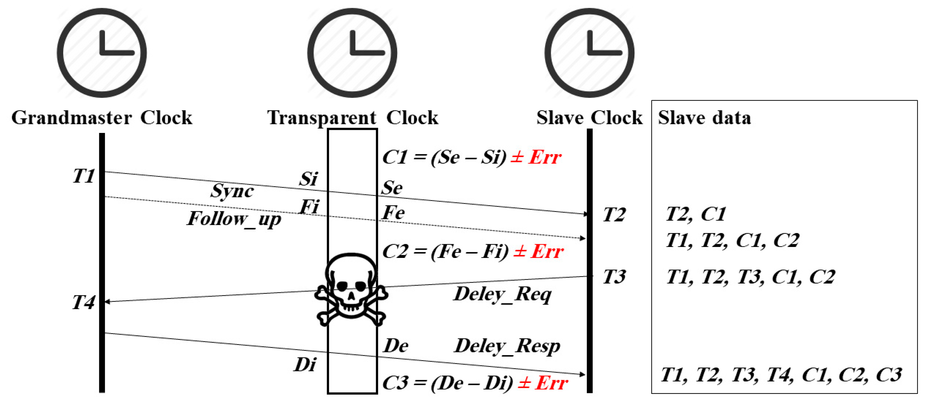
  • Systematically modify PTP message content, i.e., timestamps T1, T4, C1, C2 and/or C3, in transit via a man-in-the-middle (MitM) attacker located in an intermediate node, such as a router, switch, or transparent clock. For example, Figure 3 shows the manipulation of the correctionField segment (that contains the transparent clock residence time) of PTP messages;
  • Selectively delay PTP message propagation by a MitM to induce an asymmetric uplink/downlink delay;
  • Directly manipulate the time reference by compromising the grandmaster clock, or by introducing a Byzantine master clock. The latter requires an ordinary clock to become a rogue master (a clock that pretends to be the best in the network) by circulating announce messages with overrated clock attributes such as the PriorityOne field with the aim to manipulate the BMCA [12]. Once the device becomes the grandmaster, it propagates inaccurate timestamps and desynchronize attached slaves, and ultimately desynchronize the entire network.
This research excluded some PTP attacks (i.e., packet removal attack, master spoofing attack, slave spoofing attack, replay attack, and denial of service attack), as they may influence only individual PTP slaves or are easy to detect by PTP daemons. In contrast, the PTP attack strategies as listed above affect all slave clocks downstream from the location of the attacker, while not causing apparent changes in PTP network traffic patterns or packet content [12].
Previous research has evaluated or simulated some of these attacks. Ullmann [24] has analyzed the delay attack mathematically with a proposal to detect this attack by computing the uplink path (i.e., the delay between the master and its slave) at the beginning of synchronization and store it at the master side, while the slave computes and stores the downlink path delay. Here the attack can be detected when the new uplink/downlink path computed has a significant difference of the reference values. However, the Delay_Req message is not triggered by the arrival of a Sync message in the conventional PTP protocol and is processed on a best-effort basis, which may provide an unstable path delay over time and therefore false alarms could be triggered. Other researchers argued that redundant paths in a PTP network could detect the delay attack by comparing the offset values that are calculated by each port [14,15]. Nevertheless, APT can compromise all redundant paths, which may affect the offset values in both slave ports. Moussa [25] proposed a detection and mitigation method for the delay attack by using a redundant reference clock. However, their detection method works only for delayed Sync messages. Moussa [13] has simulated GM, TC, and asymmetric delay attacks, and they propose another network time reference to monitor the Sync messages as well as collect timestamps from slaves in order to detect an attack. However, the proposal fails in detecting some attacks if the attacker can manipulate the timestamp sent by slaves. The delay attack, packet modification attack, spoofing attack and denial of service attack have been simulated by [14], but without proposing a detection or mitigation method against these attacks. Itkin [8] has simulated some spoofing attacks as well as the BMCA attack.

2.4.2. Summary of Existing PTP Security Measures

Different protocol extensions to protect a PTP packet payload from deliberate manipulation have been introduced, but [26] has outlined the limited effectiveness of such cryptographic security protocol extensions to deflect attacks on PTP networks, particularly when orchestrated by an internal attacker that has access to network infrastructure or authentication/encryption keys. Reference [27] derives a set of conditions to secure the PTP network under the assumption that the attacker does not have access to cryptographic keys. Further on, while infrastructure redundancy [28,29,30] makes an attack more complex (as multiple/redundant system components need to be compromised, possibly in a synchronised fashion), it does not provide a provable secure way to protect PTP networks from manipulation [12]. Also, increasing the accuracy as introduced in PTP v2.1 (IEEE 1588-2019) [31] does not increase security. Girela-López [32] claims that increasing the accuracy can mitigate the asymmetric attack in normal operation, but this is not effective if an asymmetric delay is deliberately introduced. Overall, there is no comprehensive solution to this problem, and, while recent research [13] proposed an extension to PTP that collects timestamps from different slaves and compared these timestamps with another time source in order to detect clock drifts; this approach reassembles a variation of infrastructure redundancy that can be compromised by an APT.

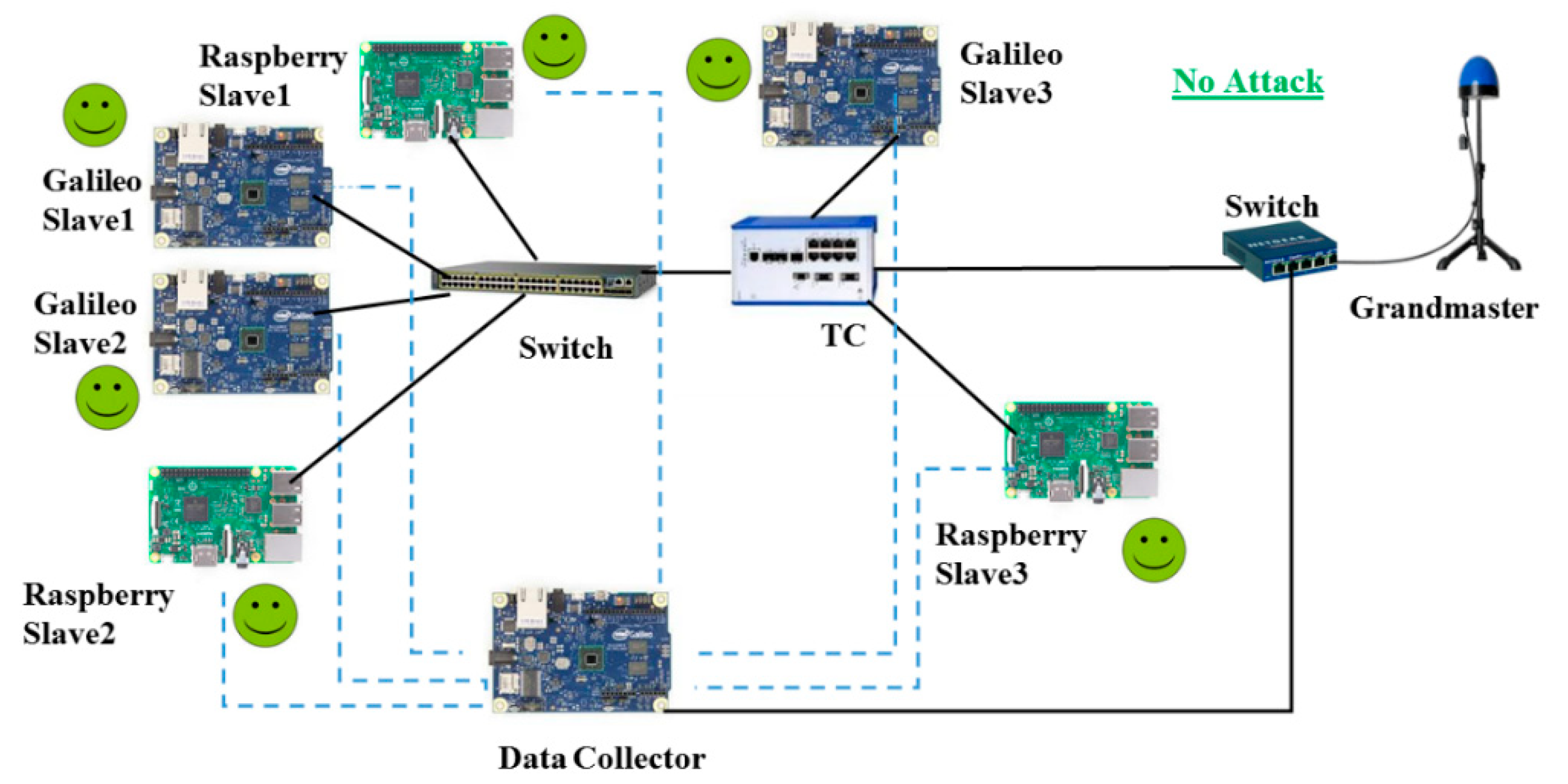
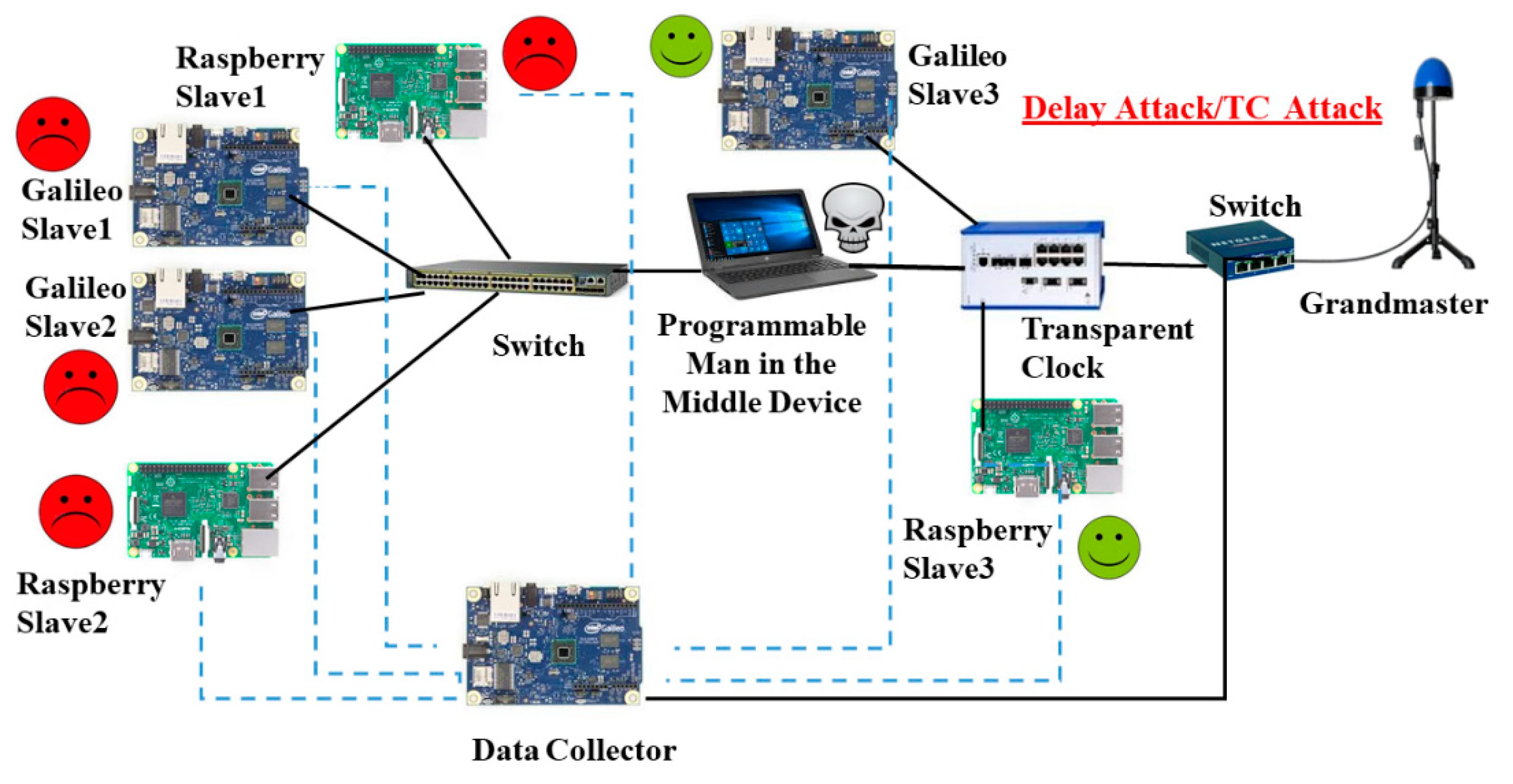
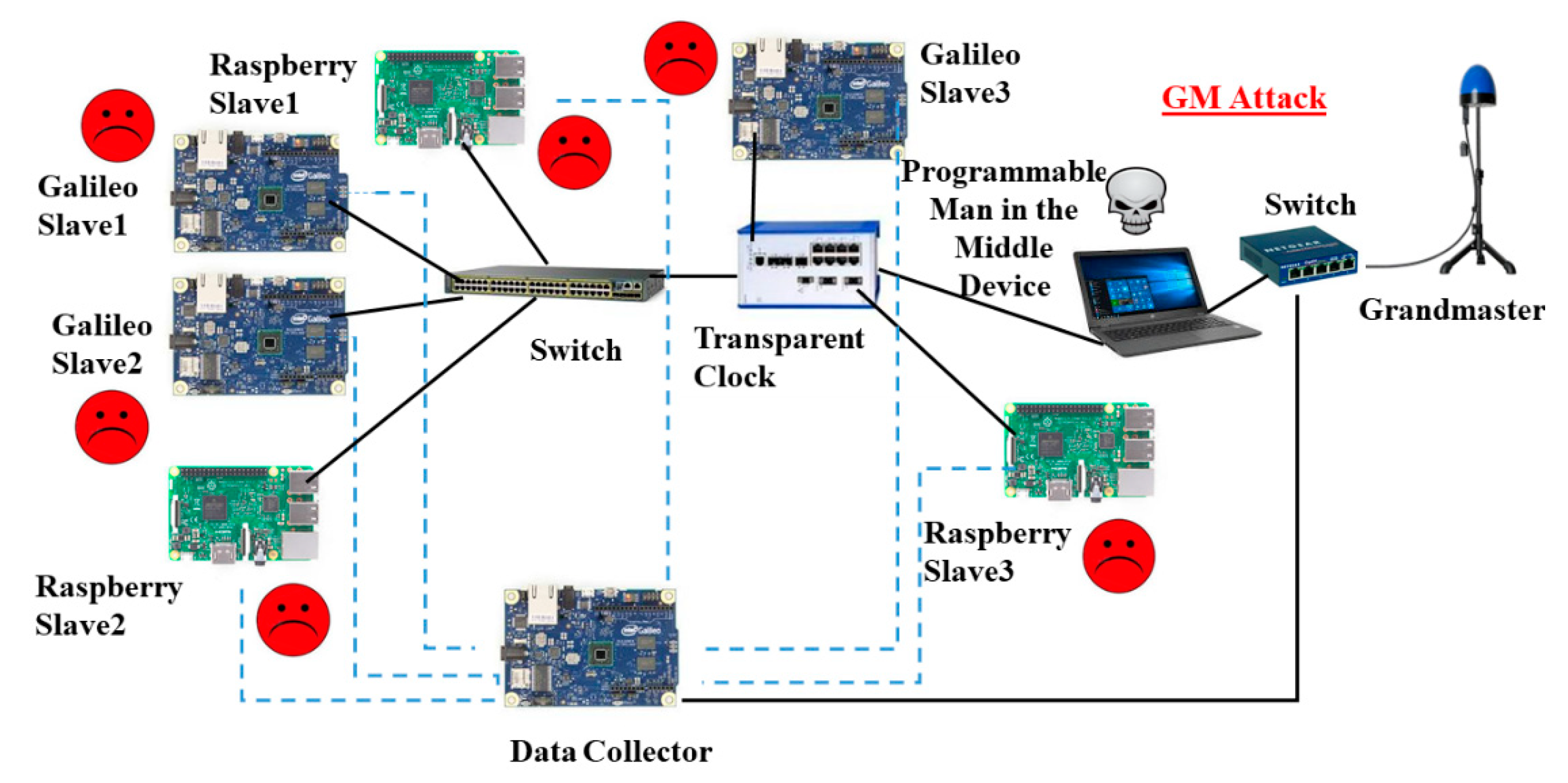
3. Testbed and MITM Device

The testbed as shown in Figure 4 contains one grandmaster clock (OMICRON OTMC 100-antenna-integrated PTP Grandmaster Clock) and two different types of slave devices (Intel Galileo Gen 1 and Raspberry Pi 3 model B) that are interconnected by ordinary switches and one transparent clock (Hirschmann RSP20). The PTP4l daemon is used by the Galileo devices, whereas PTPd is installed on the Raspberry Pi. Since the slave devices do not support hardware timestamping, all experiments were conducted using two-step operation mode. In addition, the ordinary switches used do not support the peer delay mechanism, and hence the end-to-end mechanism was used. The data collector is an ordinary slave, which is always properly synced to the GM. Its primary role is to collect PTP data from nodes under attack while providing a correct time reference. All devices in the network are connected via CAT5e Ethernet cables with a data rate of 1000 Mbps. Also, the network only carries time synchronization traffic to minimize the network load, any non-deterministic packet delay, and jitter, while the CPU load of all devices is kept at a minimum.
The MitM device is a Linux computer with two network ports. It is located in the path between a master and its slaves to intercept and manipulate PTP packets in transit. The two network ports are connected via a bridge, and the ebtables tool is used to intercept PTP packets. A user-space program written in C language manipulates the intercepted packets and forwards them to their destination. Therefore, the programmable MitM simulates the effect of APTs on time synchronization, as it allows to slowly manipulate PTP timestamps over time, for example with small increments in the order of microseconds.
Table 1 shows the time synchronization baseline (i.e., offset and mean path delay) with orderly working PTP daemons after 20 min of operation with and without a programmable MitM device in the packet path. Here the MitM is added between the GM and TC as shown in Figure 4. Please note that all offset and delay values collected during this period were computed at the same slave and were used to calculate the statistics as shown in Table 1. It can be seen that the MitM device introduces a symmetric uplink/downlink delay in the PTP packet path, as well as some jitter, as it is not a fully deterministic soft real-time system, i.e., packets are internally processed on a best-effort basis. Nonetheless, it allows for mimicking an attacker, which would otherwise be located in a switch, a GM or a TC.
While slave (quartz-oscillator) hardware clocks are inherently unstable and tend to drift [33], there are subtle differences in their quality. This is shown in Figure 5 and Figure 6, where both slave device types did run over an 8 h period (from 2 p.m. to 10 p.m.) in free-running mode and periodically sent timestamps to the GM-synchronized data collector device (as shown in Figure 4). The Galileo hardware clock shows have better stability compared to the Raspberry when exposed to different temperature conditions (24 degrees Celsius during the day dropping to 17 degrees Celsius at night), while the latter shows better accuracy.

4. Experimental Results

Four different attack types, listed in Table 2, were mimicked by the appropriately positioned MitM device. All attacks need to be persistent and continuously executed in order to effectively desynchronize a slave. GM timestamp manipulation and Byzantine attack were combined in one experiment (time source attack), as both result in incorrect grandmaster timestamps. Similarly, delayed packet transmission and correctionField manipulation were combined under one attack category (packet propagation attacks), as both result in a false path delay measurement. All experiments were conducted by using the parameters and settings as shown in Table 3. These parameters and settings correspond to many PTP profiles such as the IEEE1588 Default profile [1], ITU-T Telecom G.8275.2 profile [34], and SMTPE ST-2059-2 profile [35]. Hence, all the attacks’ effects as described in this section will be applicable to any sector that use the aforementioned profiles.
All experiments in this section were conducted over relatively short time periods to cover different attack scenarios within a reasonable timeframe. However, in a real APT such attacks could be stretched over much longer time periods (e.g., via using smaller delay increments, as further described in this section), with the overall result being the same.

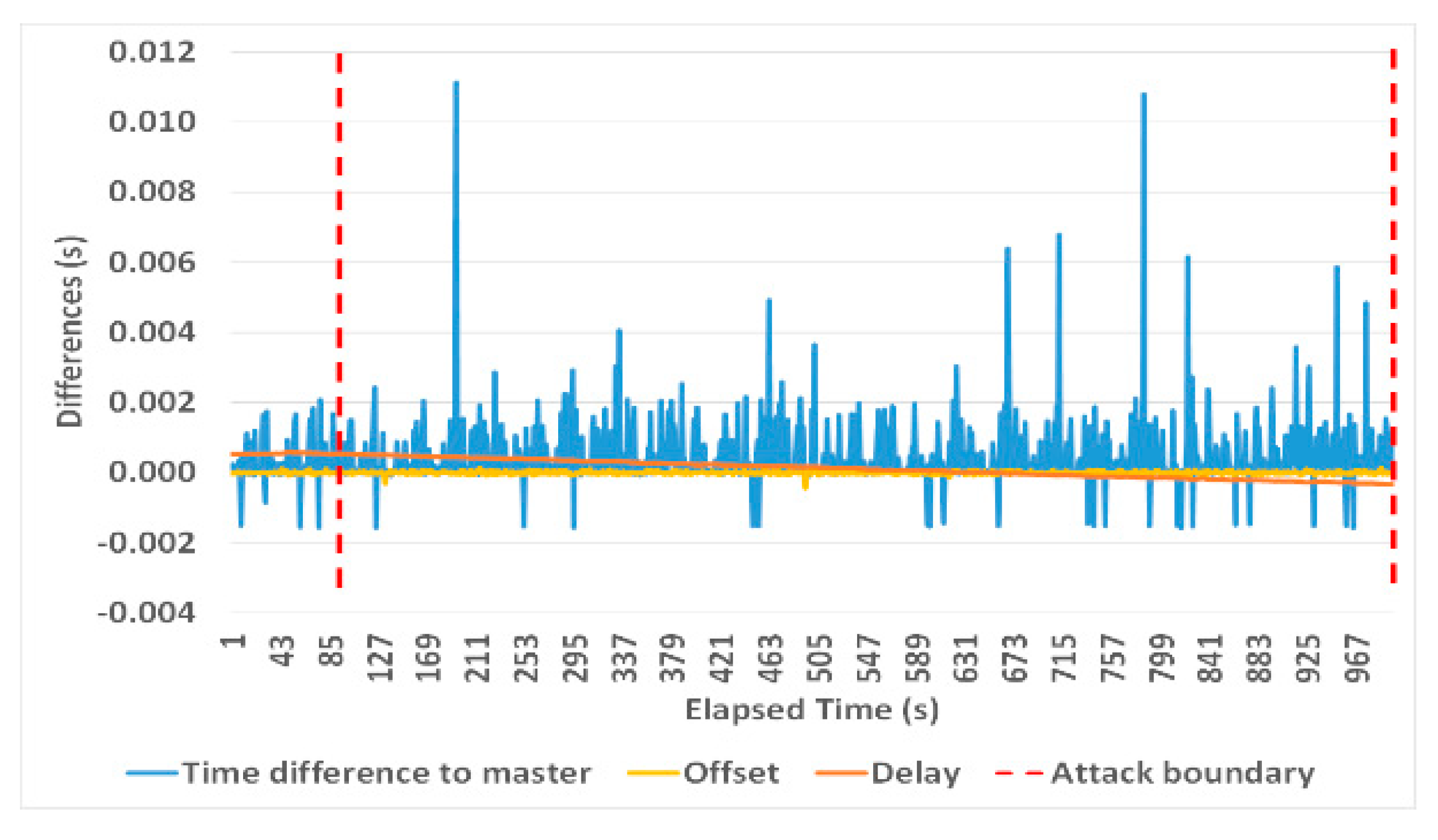
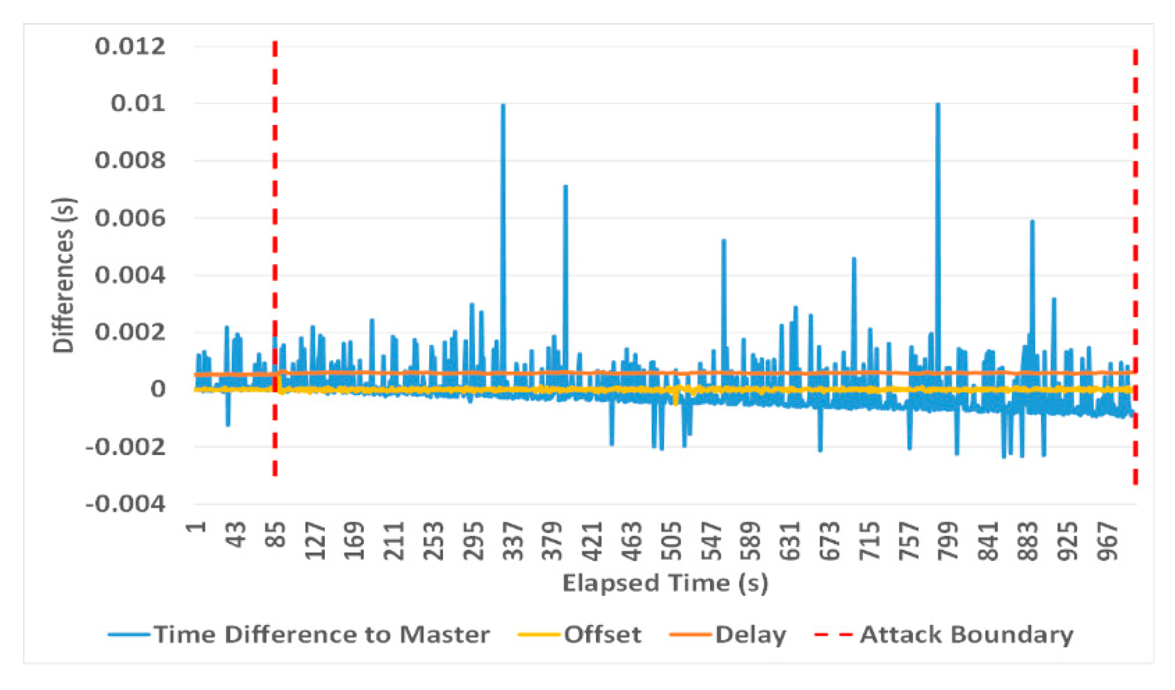
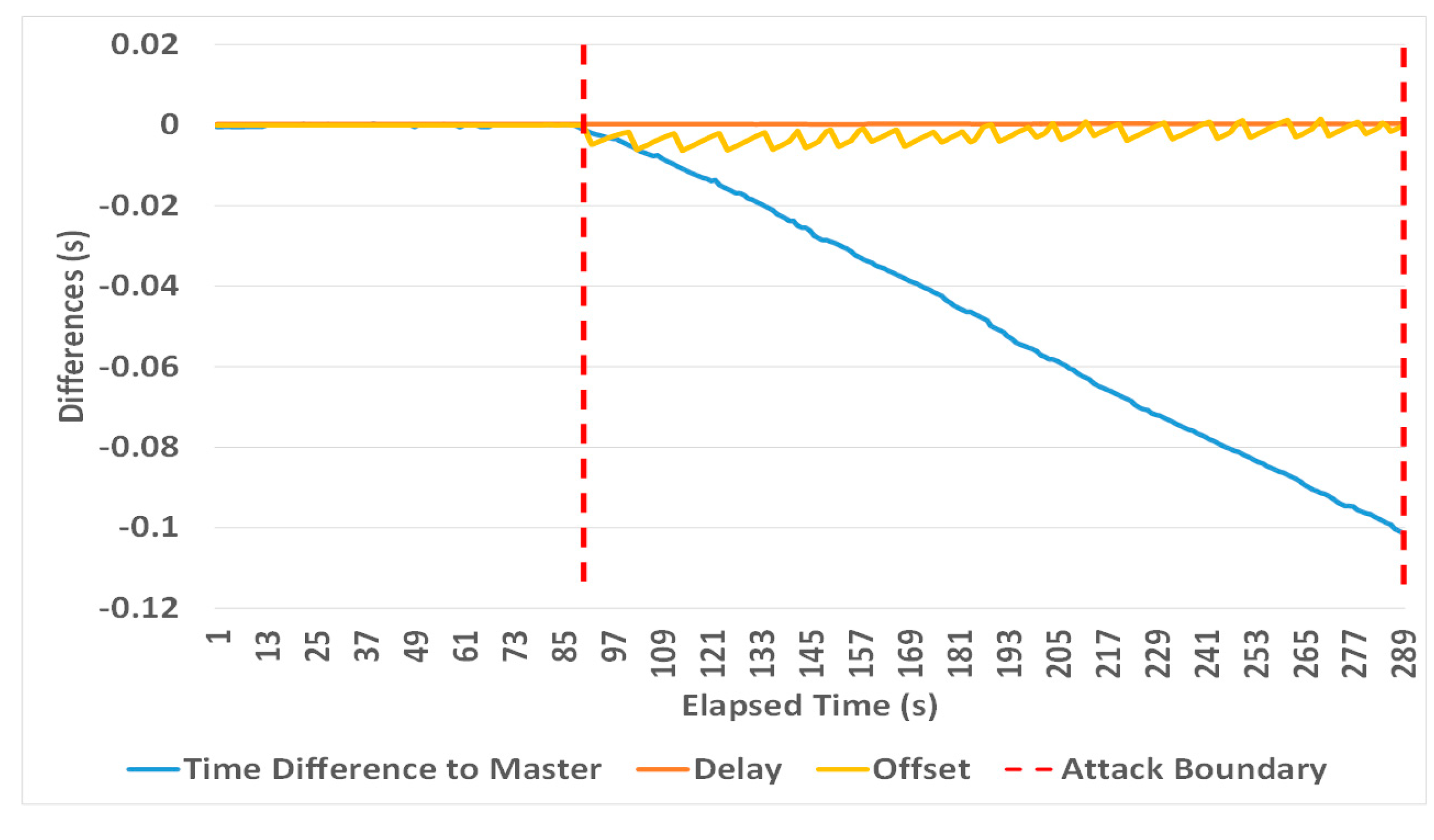
4.1. Attack 1: Packet Propagation Attack

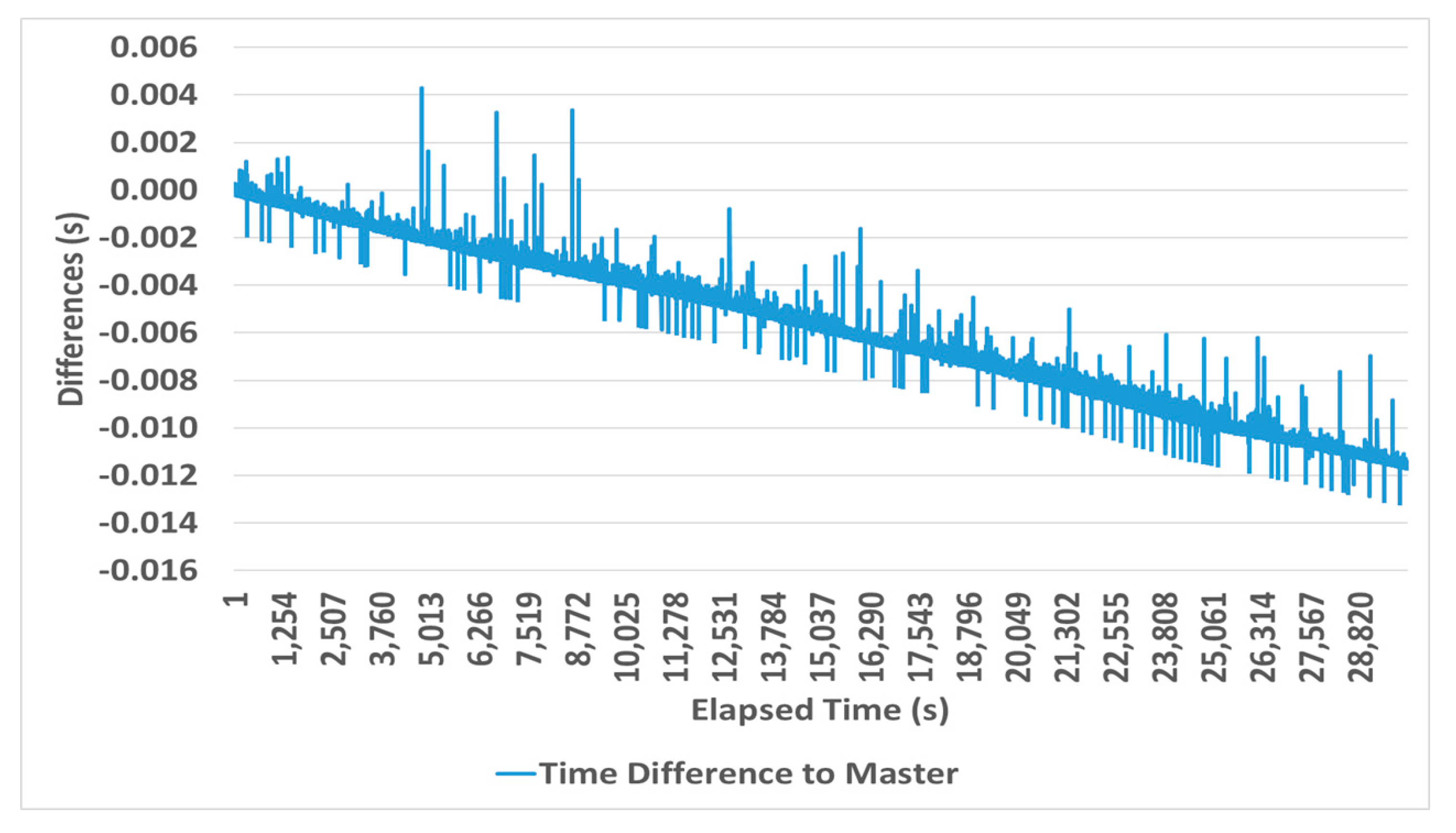
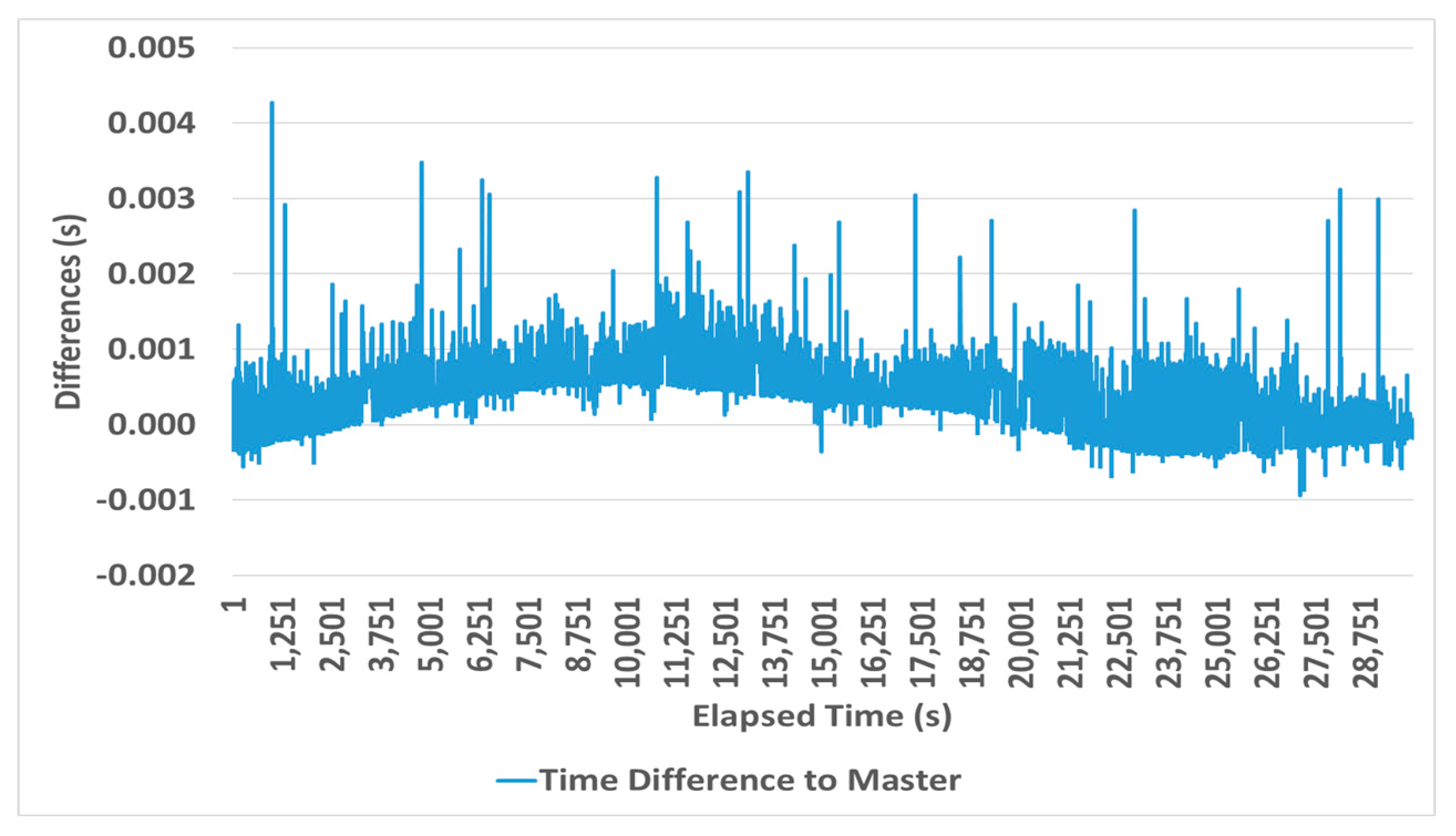
4.1.1. Delayed Packet Transmission (Compromised Switch)

Figure 7 shows the experimental setup to mimic this attack. The MitM systematically changes the residence time of synchronization packets either one-way (Sync or Delay_Req packets) or two-ways (both Sync and Delay_Req packets), introducing therefore either an asymmetric or a symmetric delay that affects timestamps T2 (arrival time of a Sync message), T4 (arrival time of a Delay_Req message), or both. Delay values are either fixed or are incremented between synchronization cycles. Table 4 provides a summary of the conducted experiments. The accumulated slave clock drift is calculated as the difference between the correctly set data collector device time and the timestamps received by the manipulated slaves plus the time taken to traverse these timestamps from the slaves to data collector. The latter also submits calculated offset and delay values, as shown in their PTP daemon’s log files. The offset and delay average calculations consider all reported values during an attack.
An asymmetric delay (downlink or uplink) results in the following:
Offset (PTPd) = ((T2 + delay) − T1 − (C1 + C2)) − ((((T2 + delay) − T1 − (C1 + C2)) + (T4 − T3)) − C3)/2
Offset (PTP4l) = ((T2 + delay) − (T1 + C1 + delayAsymmetry + C2)) − (((T2 + delay) − T3) *
frequency + (T4 − C3 − (T1 + C1 + delayAsymmetry + C2)))/2
meanPathDelay (PTPd) = ((((T2 + delay) − T1 − (C1 + C2)) + (T4 − T3)) − C3)/2
meanPathDelay (PTP4l) = ((((T2 + delay) − T3) * ratio) + ((T4 − C3) − (T1 + C1 + C2)))/2
Offset (PTPd) = (T2 − T1 − (C1 + C2)) − (((T2 − T1 − (C1 + C2)) + ((T4 + delay) − T3)) − C3)/2
Offset (PTP4l) = (T2 − (T1 + C1 + delayAsymmetry + C2)) − ((T2 − T3) * frequency + ((T4 +
delay) − C3 − T1 + C1 + delayAsymmetry + C2)))/2
meanPathDelay (PTPd) = (((T2 − T1 − (C1 + C2)) + ((T4 + delay) − T3)) − C3)/2
meanPathDelay (PTP4l) = (((T2 − T3) * ratio) + (((T4 + delay) − C3) − (T1 + C1 + C2)))/2
where delay represents the added delay introduced by an attacker.
Equations (13)–(16) show how the offset and delay are affected (in both daemons) when an attacker increments the delay from the master to its slaves, while Equations (17)–(20) show the opposite effect i.e., increment the delay from the slaves to their master.
Adding a notable fixed delay (i.e., in the order of milliseconds) to either the uplink or downlink path results in an instantaneous spike of the offset error, as shown in Figure 8 and Figure 9, which can be easily picked up by a PTP slave daemon, while a single smaller fixed delay that blends in with normally occurring delay measurement fluctuations (i.e., in the order of microseconds) do not have a significant impact on slave clock desynchronization. This leads to the conclusion that a high-impact APT requires carefully selected incremental path delays over time.
Figure 10 and Figure 11 show the observed offset, delay and clock errors, when a (Galileo-PTP4l) and (Raspberry–PTPd) slaves were exposed to an asymmetric delay (where Sync message transmissions were delayed) with 5 ms increments per second from about 90 s into the experiment, resulting in a slave clock error of 93 ms (Galileo) and 101 ms (Raspberry) after 200 s of an attack. It is notable that the introduced delay increment is too large to be immediately compensated by slave clock frequency adjustments (which are limited to 512 ppm per synchronization cycle throughout all experiments), resulting in a noticeable cumulated offset error over time. This can be avoided, if the increment is limited to a compensable error as shown in Figure 12 and Figure 13. Here the delay was reduced to 10 μs every second from about 90 s into the experiment, resulting in a slave clock error of around 5 ms after 910 s of the attack and an observable delay drift, while the offset error remained unchanged.
Manipulating a switch’s firmware to introduce delays only in one direction may not be feasible; therefore the impact of a symmetric delay attack was investigated, where a switch would apply a delay to all packets that cross it. Any fixed symmetric delay is naturally compensated by PTP (see (1)), as shown in Figure 14 and Figure 15, while small symmetric delay increments have no effect either (Figure 16 and Figure 17). However, introducing a symmetric delay increment of 5 ms per second shows some unexpected results, as the time synchronization error increased to around 84 ms (Galileo) and 61 ms (Raspberry) after 200 s into the attack, also showing a delayed increase of the measured offset errors (Figure 18 and Figure 19); here, the offset eventually starts drifting after the introduced delay amount exceeds the delay request interval that was set to one second (Table 3). This behavior is a result of the PTP client software implementation mentioned before, where GM-initiated sync packets and slave-initiated delay measurements are not synchronized and are affected by different delay increments.
It can be concluded that delay measurement variations could be a potential indicator to detect a delay attack, as Figure 10, Figure 11, Figure 12 and Figure 13 and Figure 18 show that the delay distribution follows the time error distribution. Also, Table 1 and Table 4 show that the calculated delay averages are different and do change due to the attack.
In summary, an attacker can use the delay attack to desynchronize slave clocks efficiently as follows:
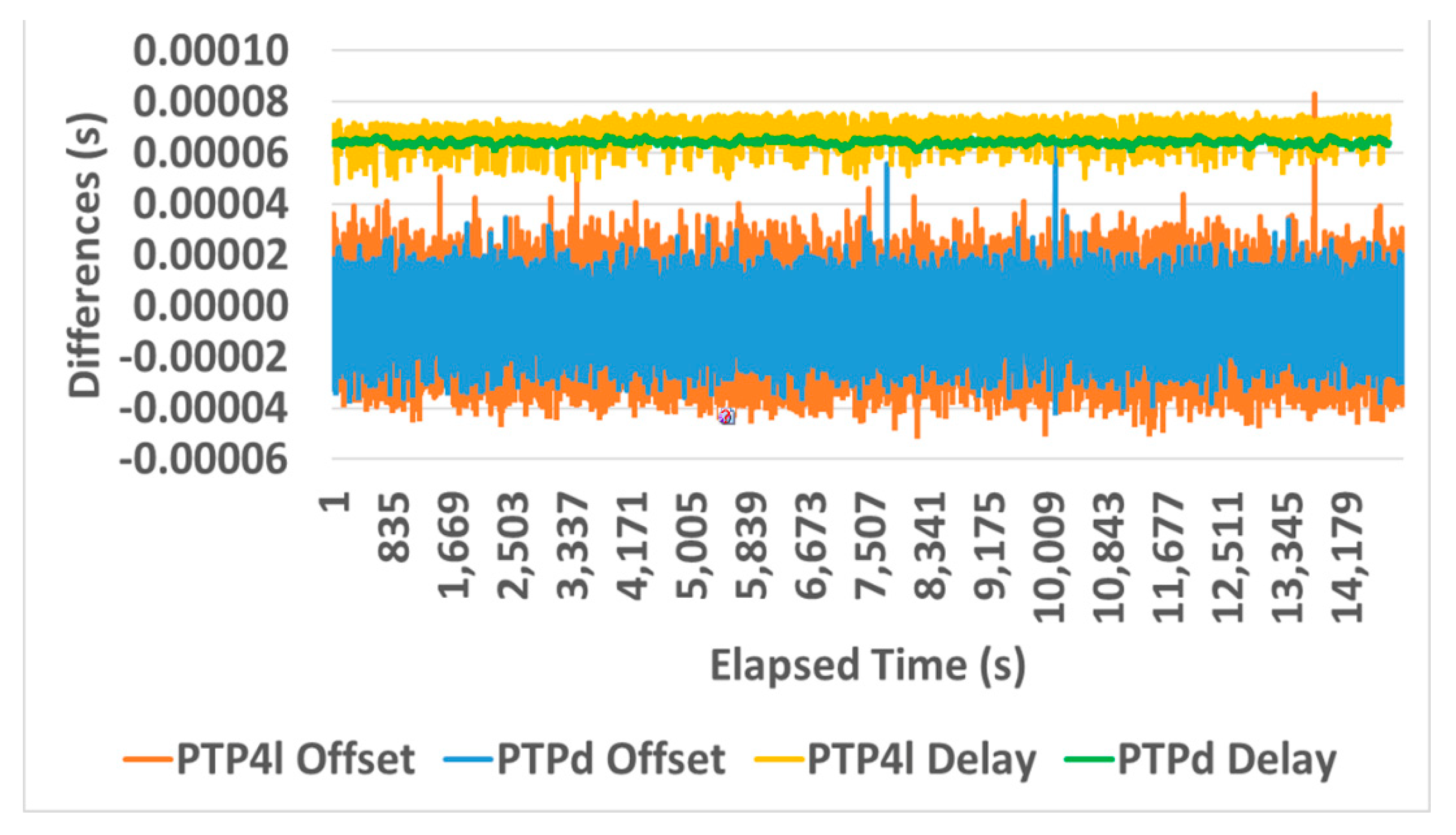
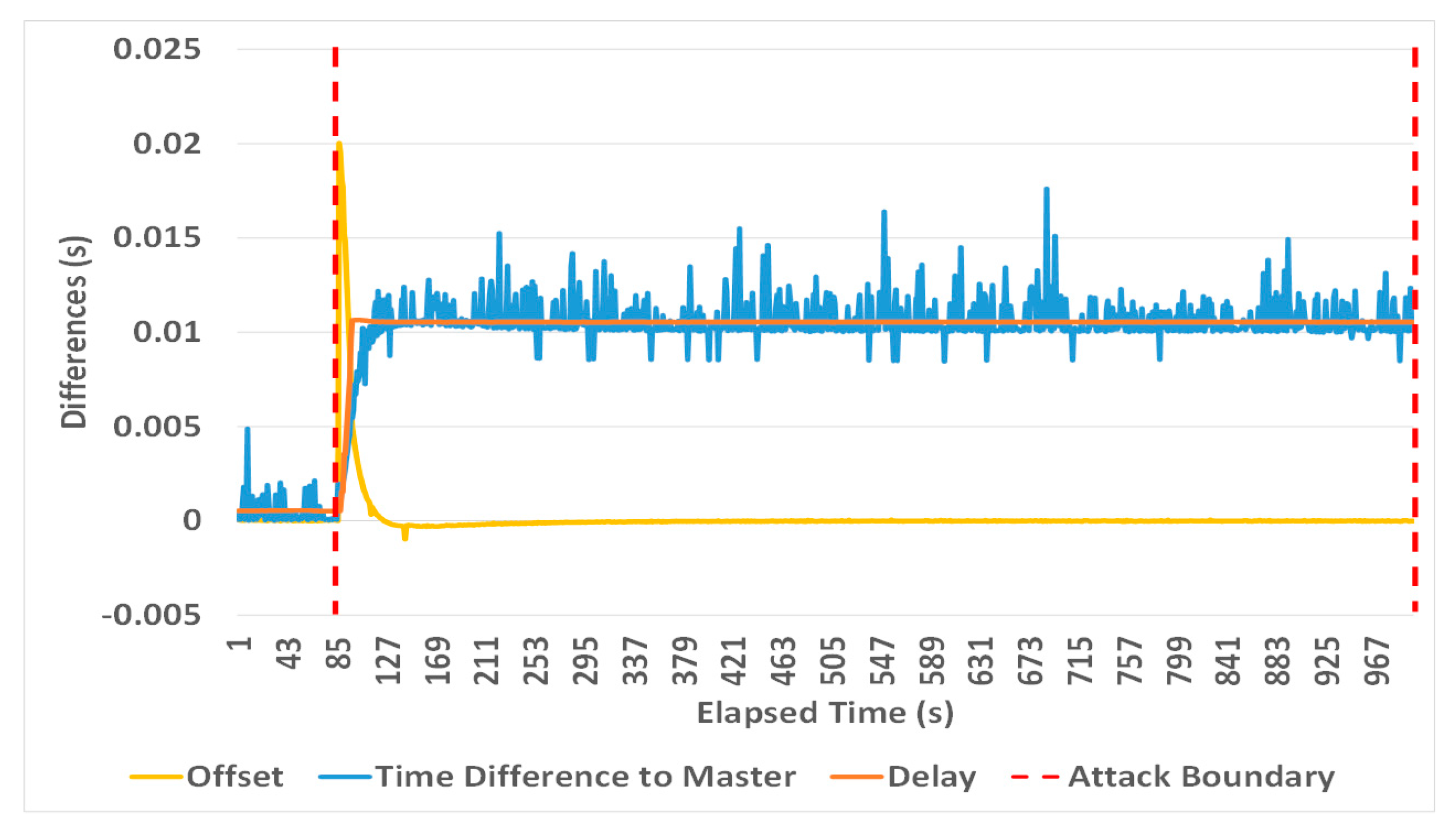
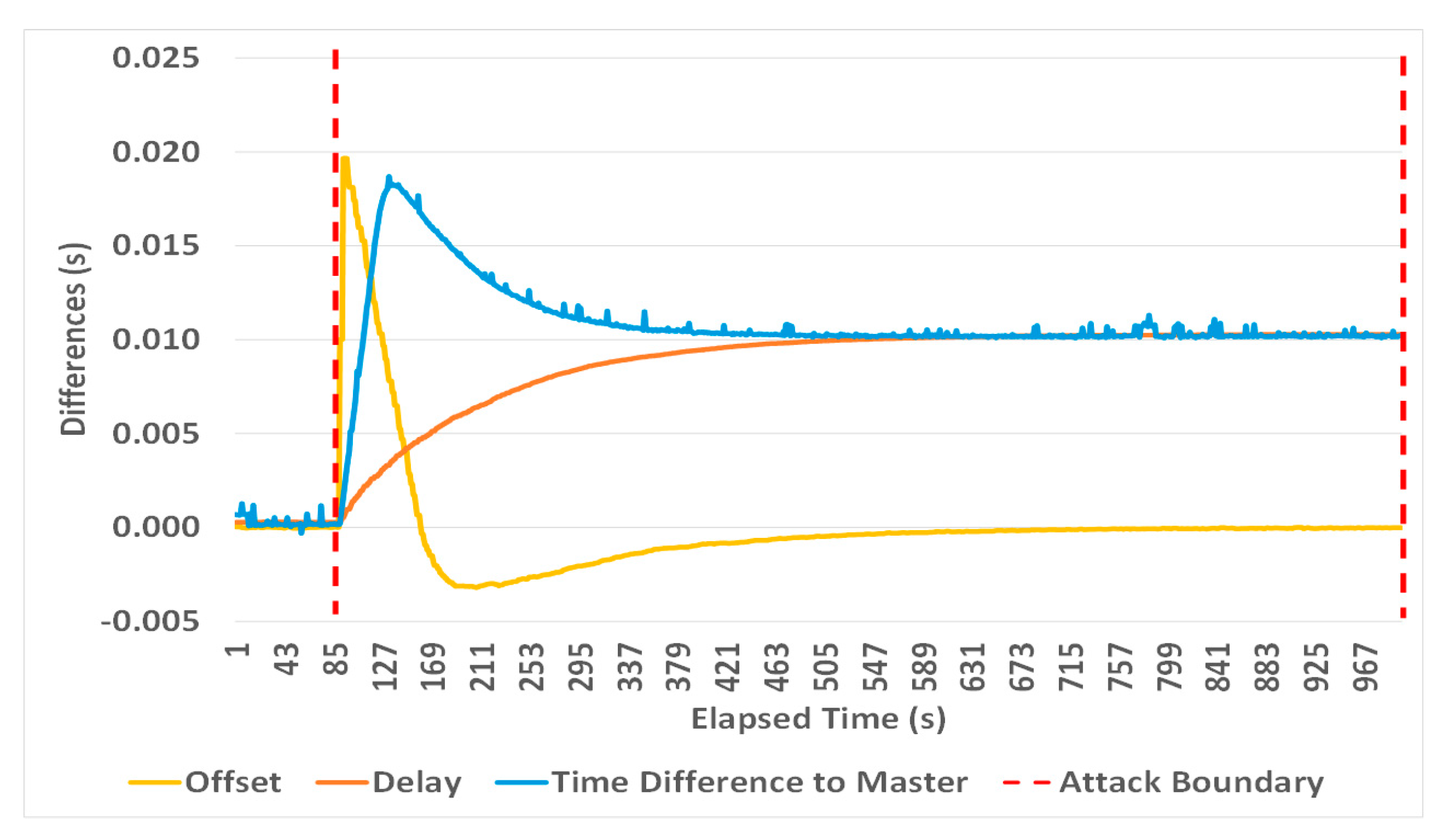
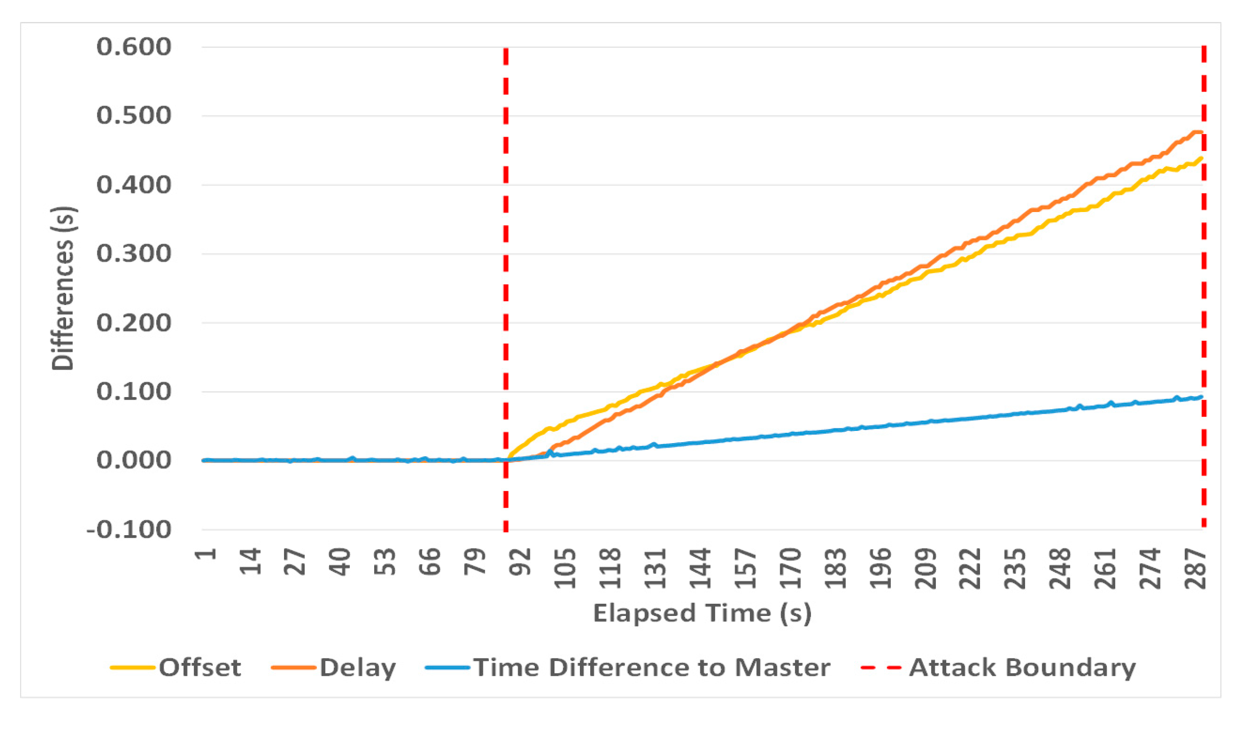
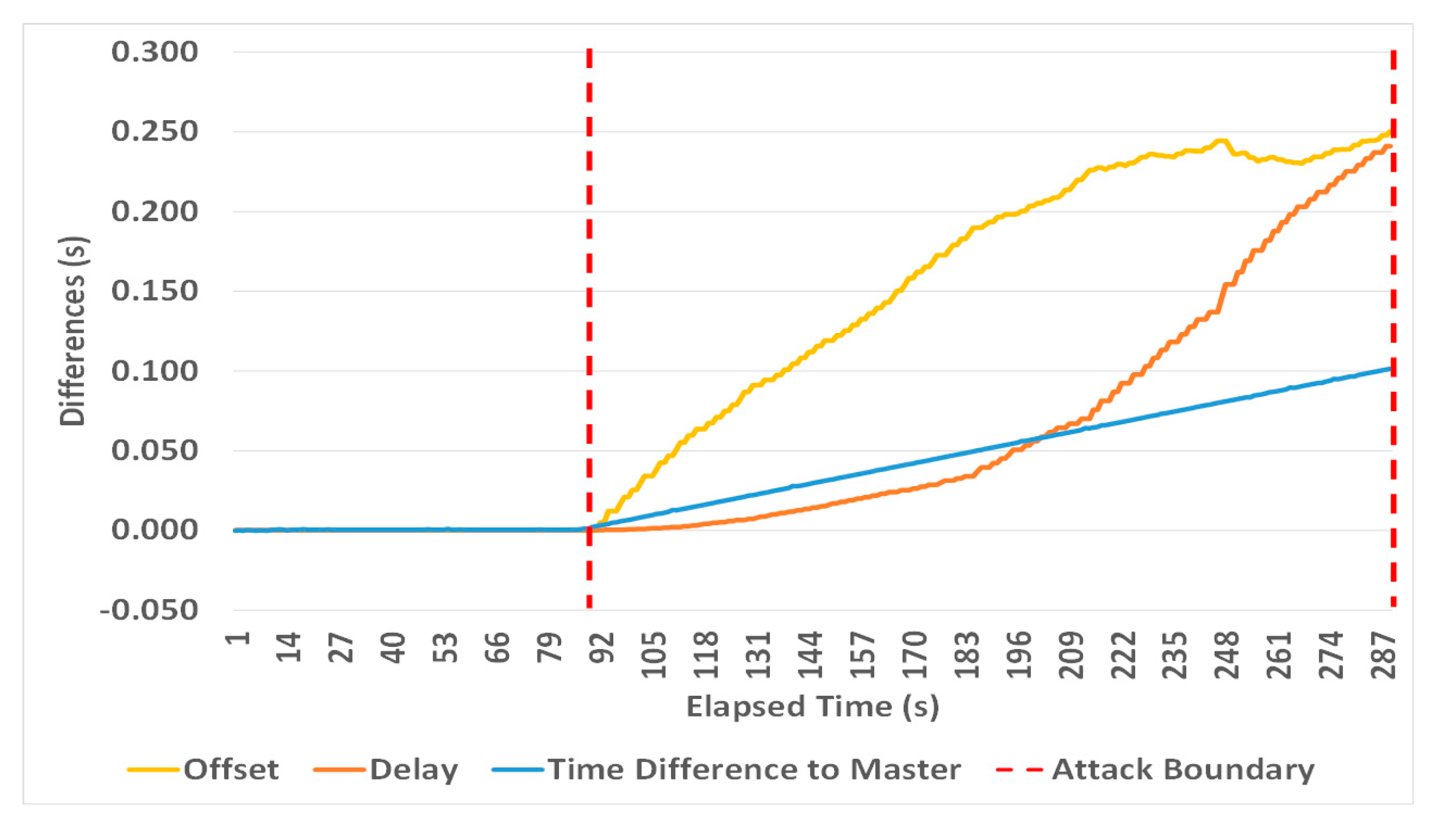
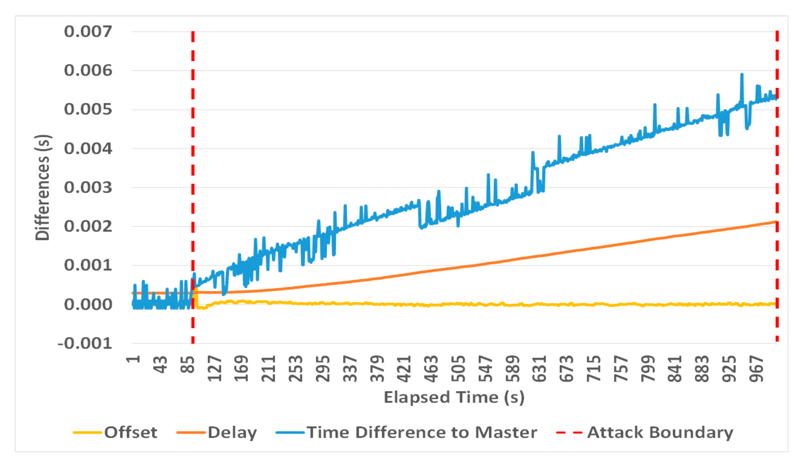
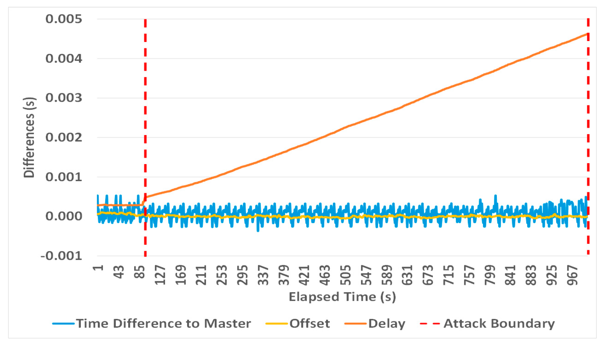
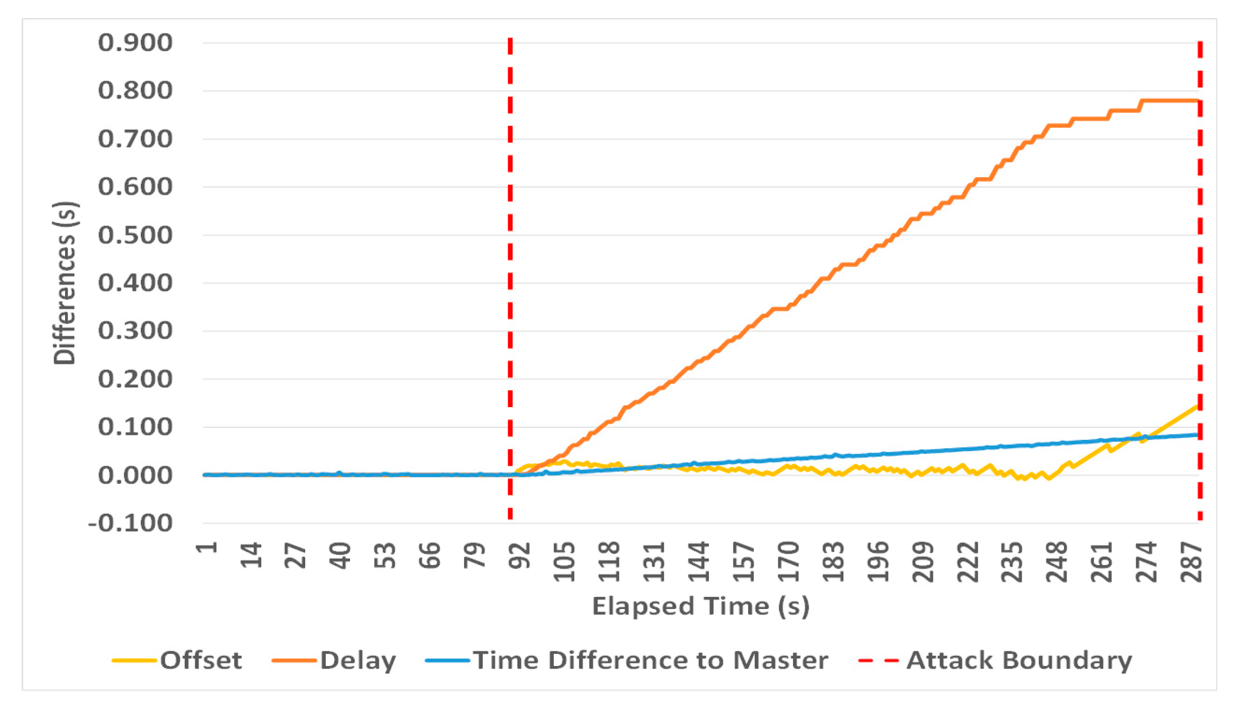
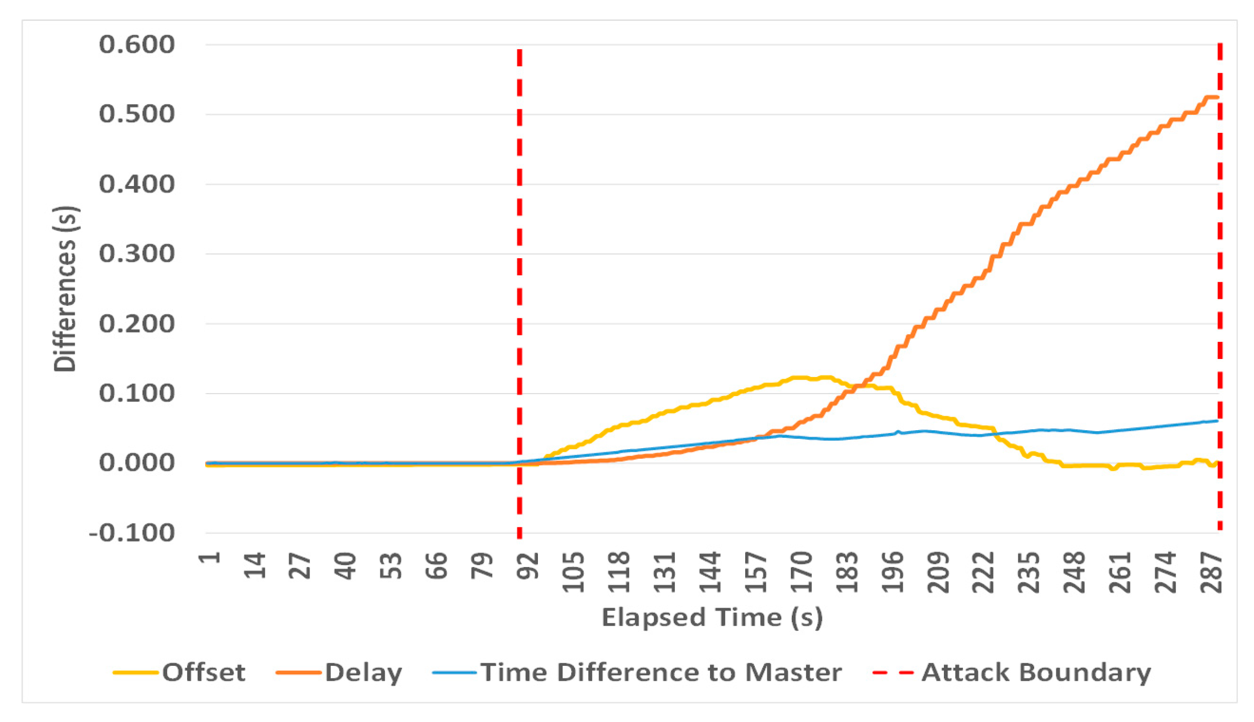
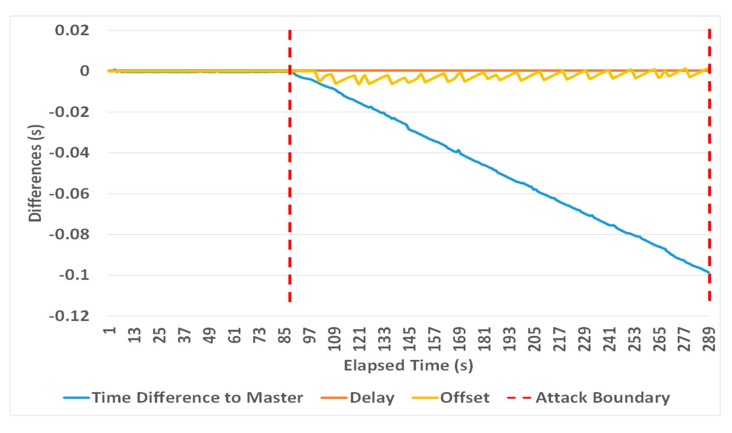
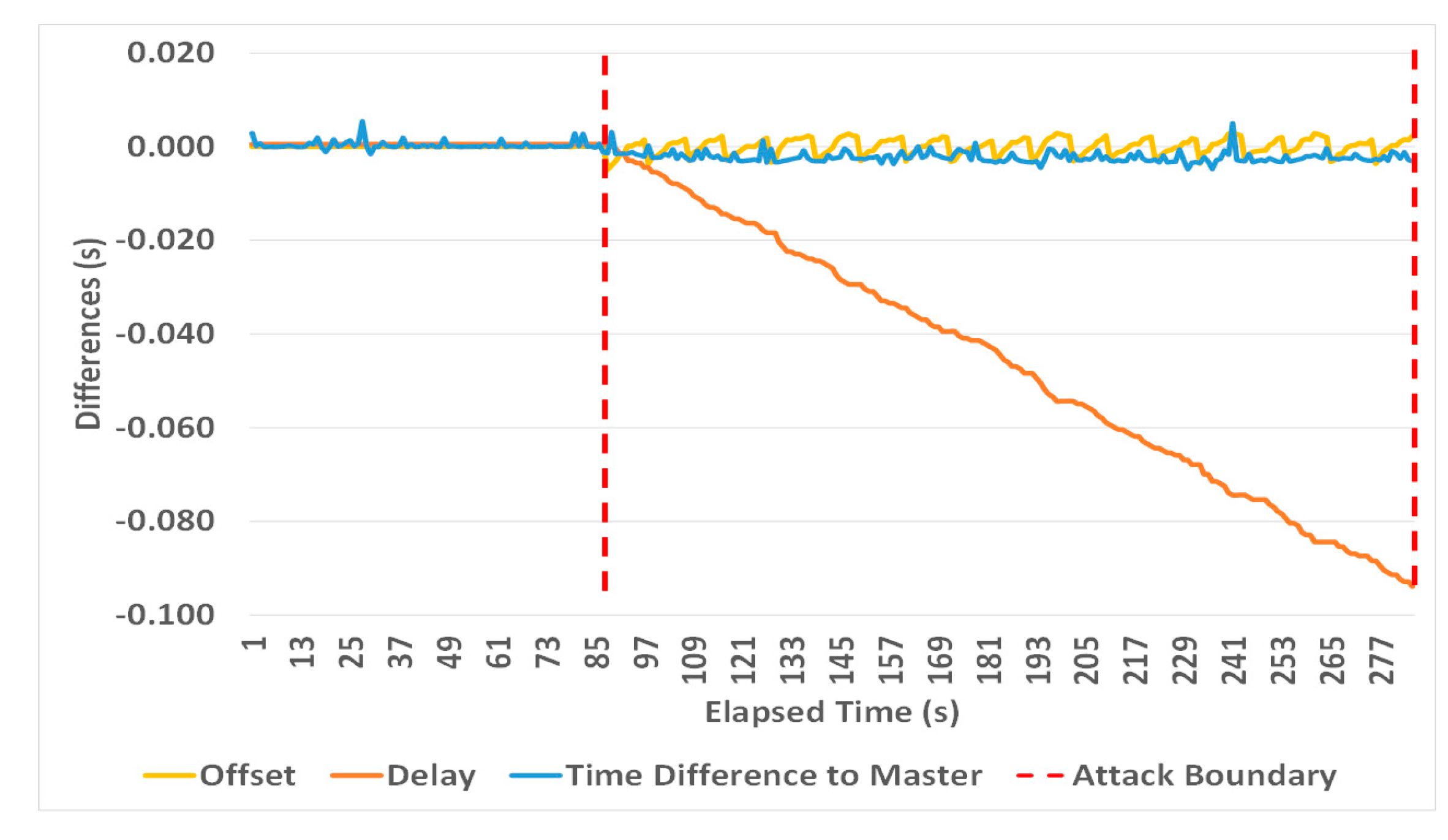
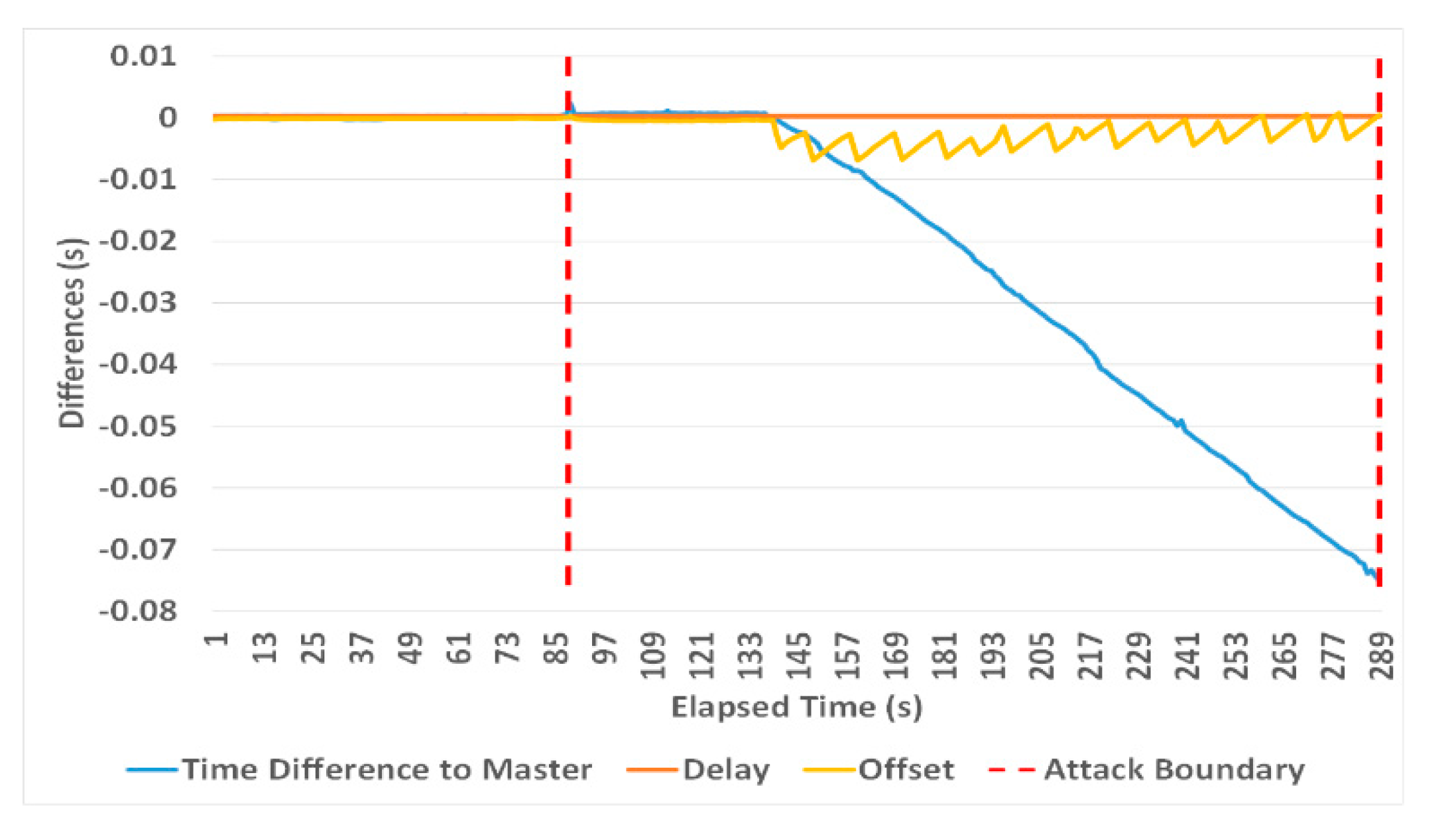
  • Introduce an asymmetric delay in the path between the slaves and their master, resulting in a slave clock drift approximately half the maximum asymmetric delay (e.g., Figure 8 and Figure 9 show how the slaves drift by 10 ms as a result of a 20 ms asymmetric delay). Here smaller increments result in a small adjustment in the clock frequency and less apparent fluctuations of a slave clock offset.
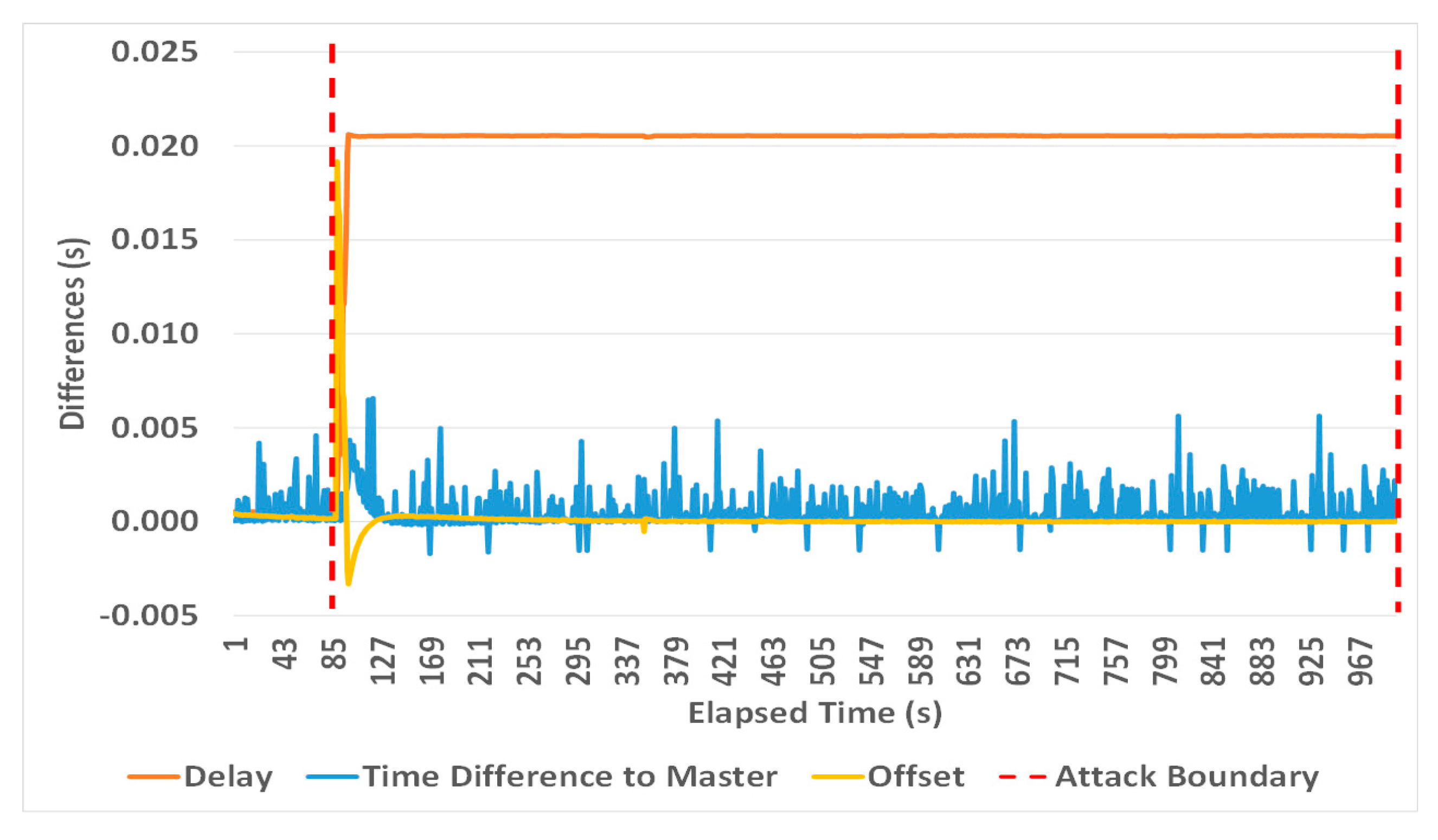
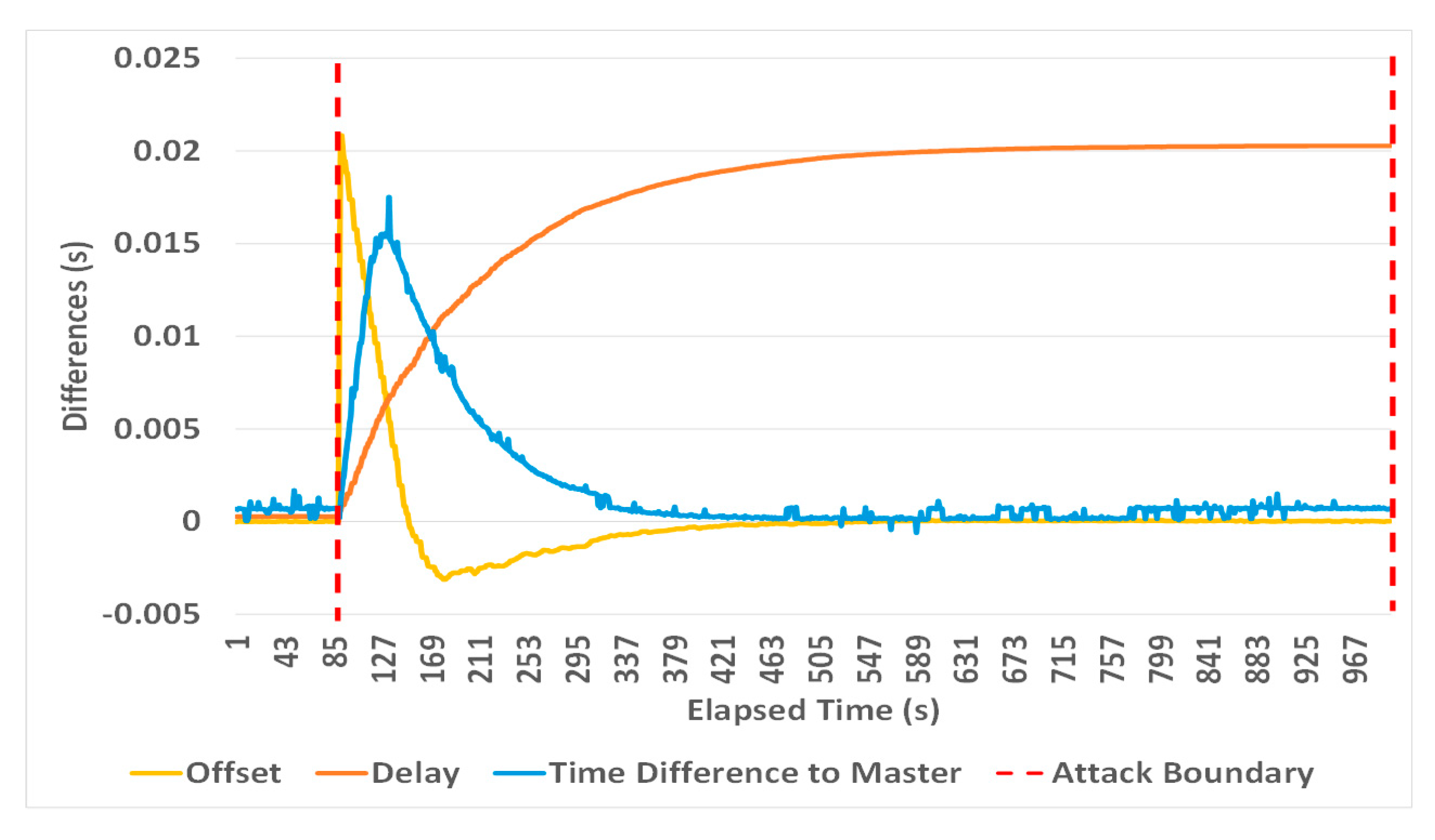
  • Introduce a consecutive large delay in the uplink and downlink path between the master and its slaves that makes a slave clock always slew with the maximum frequency. Here, the value of the slave clock drift is variable and subject to the PTP daemon type and the filtering mechanism that is applied. Such an attack causes an increased slave clock offset over time, which makes the attack easy to be detectable.

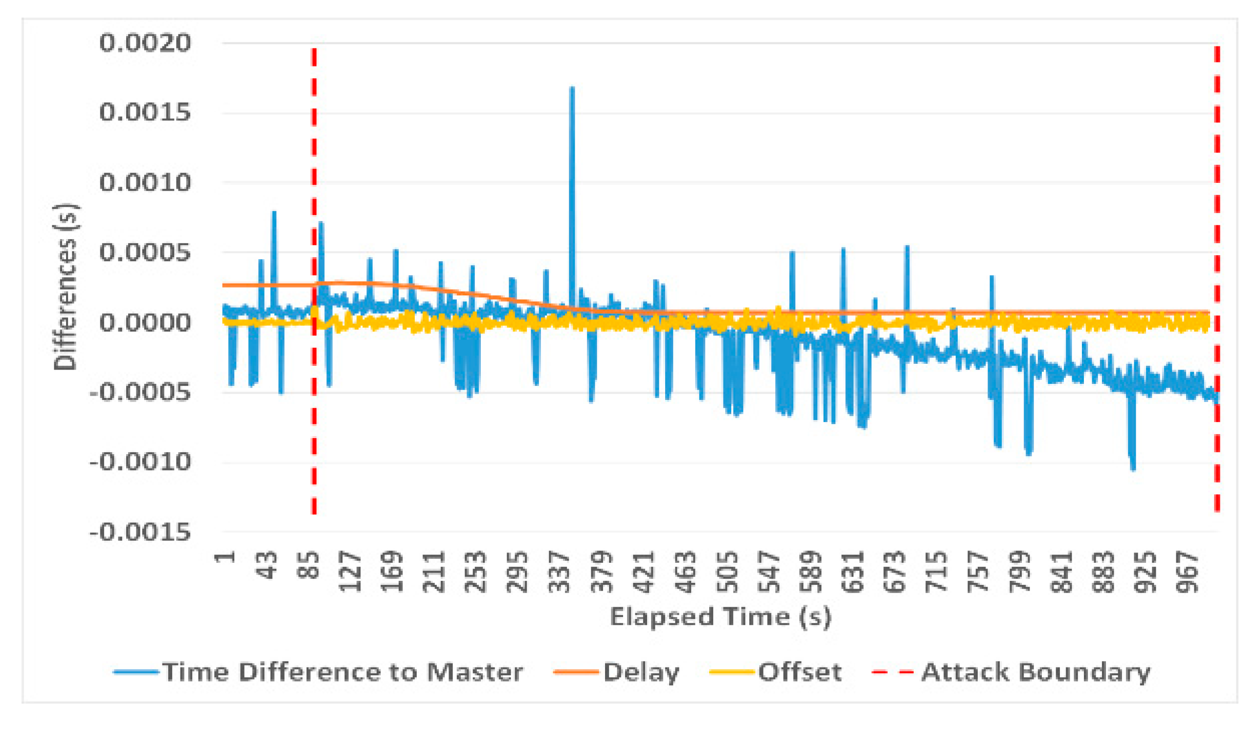
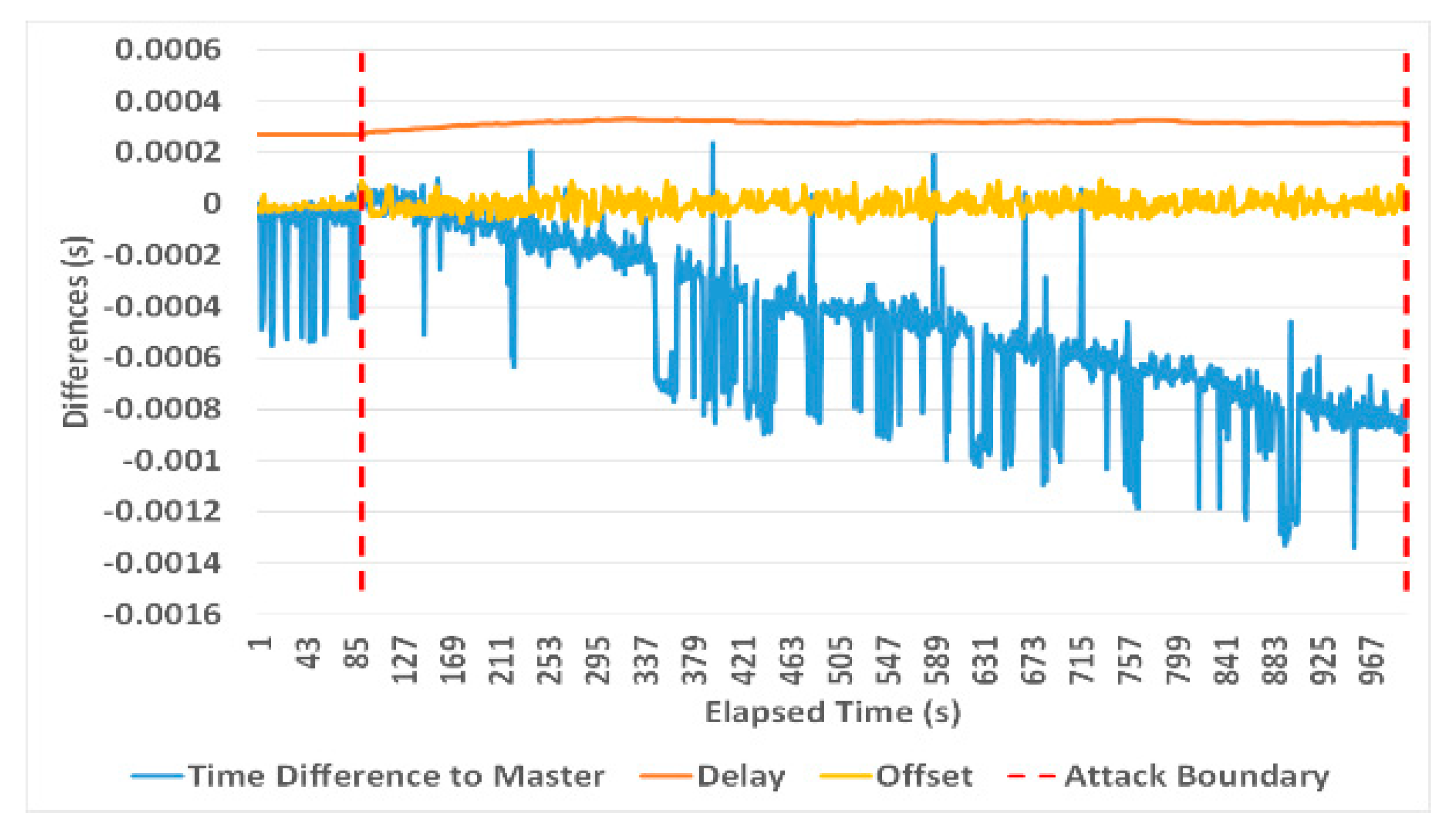
4.1.2. CorrectionField Manipulation (Compromised TC)

Here the MitM attacker intercepts the Follow_Up and/or Delay_Resp messages and gradually changes their correction field value (as normally done by a TC) to provide a false path delay (see Figure 7). Providing a false C2 (correctionField of Follow_Up message) or/and C3 (correctionField of Delay_Resp message) introduces inaccurate offset and mean path delay values accordingly as follows:
Offset (PTPd) = (T2 − T1 − (C1 + C2 + Err)) − (((T2 − T1 − (C1 + C2 + Err)) + (T4 − T3)) − C3)/2
Offset (PTP4l) = (T2 − (T1 + C1 + delayAsymmetry +C2 + Err)) − ((T2−T3) * frequency + (T4 −
C3 − (T1 + C1 + delayAsymmetry +C2 + Err)))/2
meanPathDelay (PTPd) = (((T2 − T1 − (C1 + C2 + Err)) + (T4 − T3)) − C3)/2
meanPathDelay (PTP4l) = (((T2 − T3) * ratio) + ((T4 − C3) − (T1 + C1 + C2 + Err)))/2
Offset (PTPd) = (T2 − T1 − (C1 + C2)) − (((T2 − T1 − (C1 + C2)) + (T4 − T3)) − (C3 + Err))/2
Offset (PTP4l) = (T2 − (T1 + C1 + delayAsymmetry +C2)) − ((T2 − T3) * frequency + (T4 − (C3
+ Err) − (T1 + C1 + delayAsymmetry + C2)))/2
meanPathDelay (PTPd) = (((T2 − T1 − (C1 + C2)) + (T4 − T3)) − (C3 + Err))/2
meanPathDelay (PTP4l) = (((T2 − T3) * ratio) + ((T4 − (C3 + Err)) − (T1 + C1 + C2)))/2
Offset (PTPd) = (T2 − T1 − (C1 + C2+ Err)) − (((T2 − T1 − (C1 + C2 + Err)) + (T4 − T3)) − (C3 + Err))/2
Offset (PTP4l) = (T2 − (T1 + C1 + delayAsymmetry + C2 + Err)) − ((T2−T3) * frequency + (T4 −
(C3 + Err) − (T1 + C1 + delayAsymmetry + C2+ Err)))/2
meanPathDelay (PTPd) = (((T2 − T1 − (C1 + C2 +Err)) + (T4 − T3)) − (C3 + Err))/2
meanPathDelay (PTP4l) = (((T2 − T3) * ratio) + ((T4 − (C3 + Err)) − (T1 + C1 + C2+ Err)))/2
where Err represents the added time value introduced by an attacker.
Equations (21)–(24) show how the offset and delay are affected (in both daemons) when an attacker manipulates the correctionField value of Follow_Up messages, while Equations (25)–(28) show the opposite effect i.e., manipulates the correctionField of Delay_Resp messages. In contrast, the symmetric manipulation (i.e., the attacker manipulates the correctionField of Follow_Up and Delay_Resp messages with the same increment) are shown in Equations (29)–(32).
Table 5 provides a summary of the conducted experiments. They were based on the experiments of the previous section with the difference that the MitM attacker manipulates only the correctionField of either the Follow_Up message or Delay_Resp message to provide an asymmetric manipulation, or manipulate both (Follow_Up and Delay_Resp) to provide a symmetric manipulation when they pass the MitM node as shown in Figure 7. In all experiments, Err was increased every 10 s, while the other attack parameters remained untouched.
Figure 20, Figure 21, Figure 22 and Figure 23 show that an incremental correctionField offset in Follow_Up/Delay_Resp messages causes a proportional desynchronization of the affected slave. Resulting delays are compensated for by the aforementioned clock adjustment mechanisms, therefore the offset oscillations shown in the diagrams.
Increasing the correctionField value of Follow_Up/ Delay_Resp messages may cause the calculated mean path delay to become smaller than zero. PTP4l accepts these values as shown in the figures, and can therefore be used as an indicator for this attack. In contrast, PTPd rejects any negative path delay (from master to slave or slave to master) and it uses the last valid non-negative mean path delay calculated instead as described in Section 2. This makes the mean path delay value keeping the last valid value calculated before the attack, therefore the delay appears as a straight line (see Figure 21 and Figure 23). As a result PTPd’s delay calculations cannot be used to indicate this attack, which is a major weakness that can be specifically exploited in a PTP attack.
Figure 24, Figure 25, Figure 26 and Figure 27 show the impact of a symmetric TC attack on both clients with a similar ripple effect on offset values. PTP4l shows robustness against this attack with very small slave clock time deviations and easy detectable delay measurements. PTPd, in contrast, shows significant slave time errors and normal delay values. Again, this is a major weakness that can be specifically exploited in a PTP attack. This attack causes a time synchronization error ranging from hundreds of microseconds to 98 ms depending on the attack parameters and PTP daemon type as shown in Table 5.
In summary, an attacker can use the correctionField attack to desynchronize slave clocks efficiently as follows:
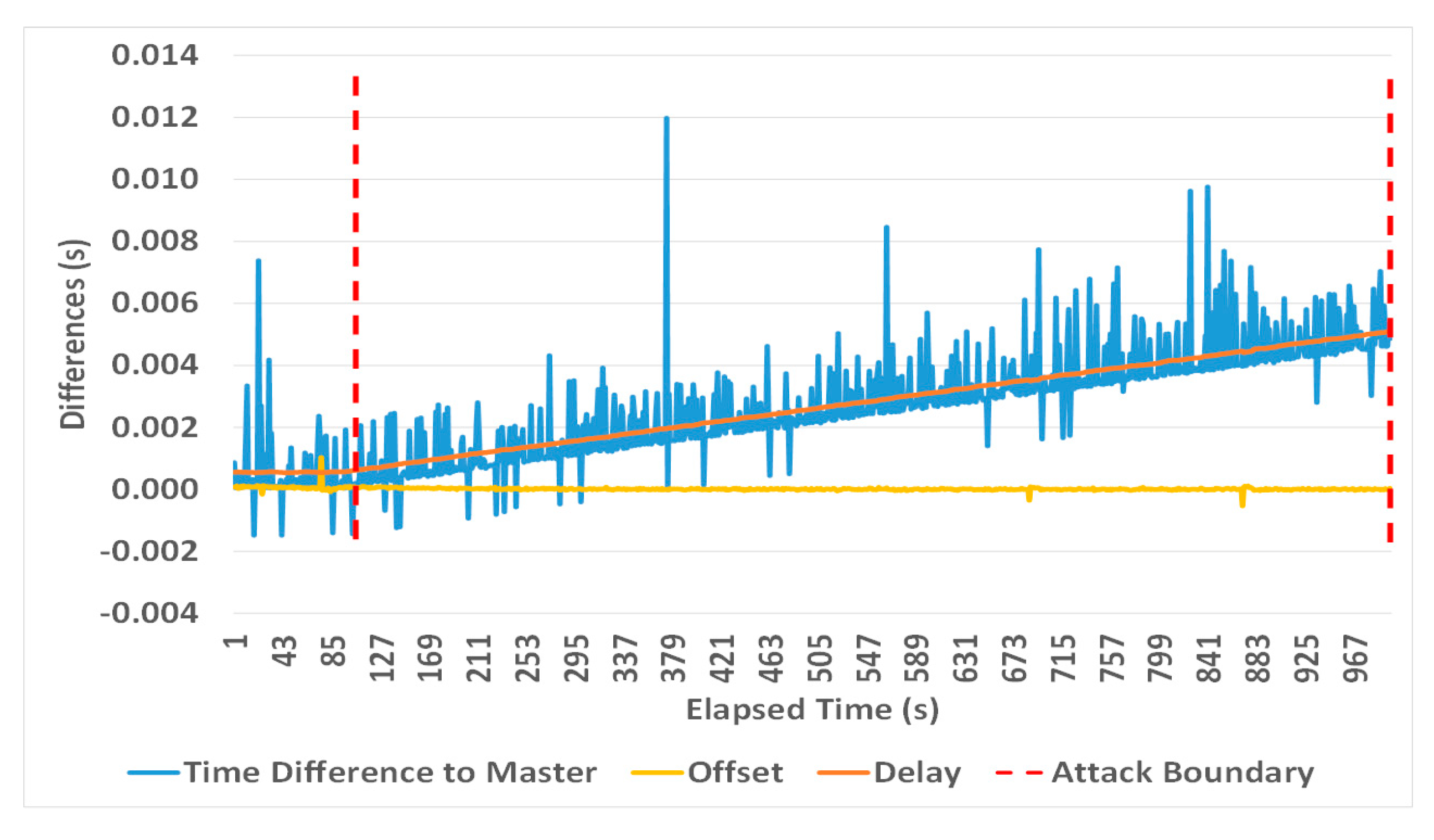
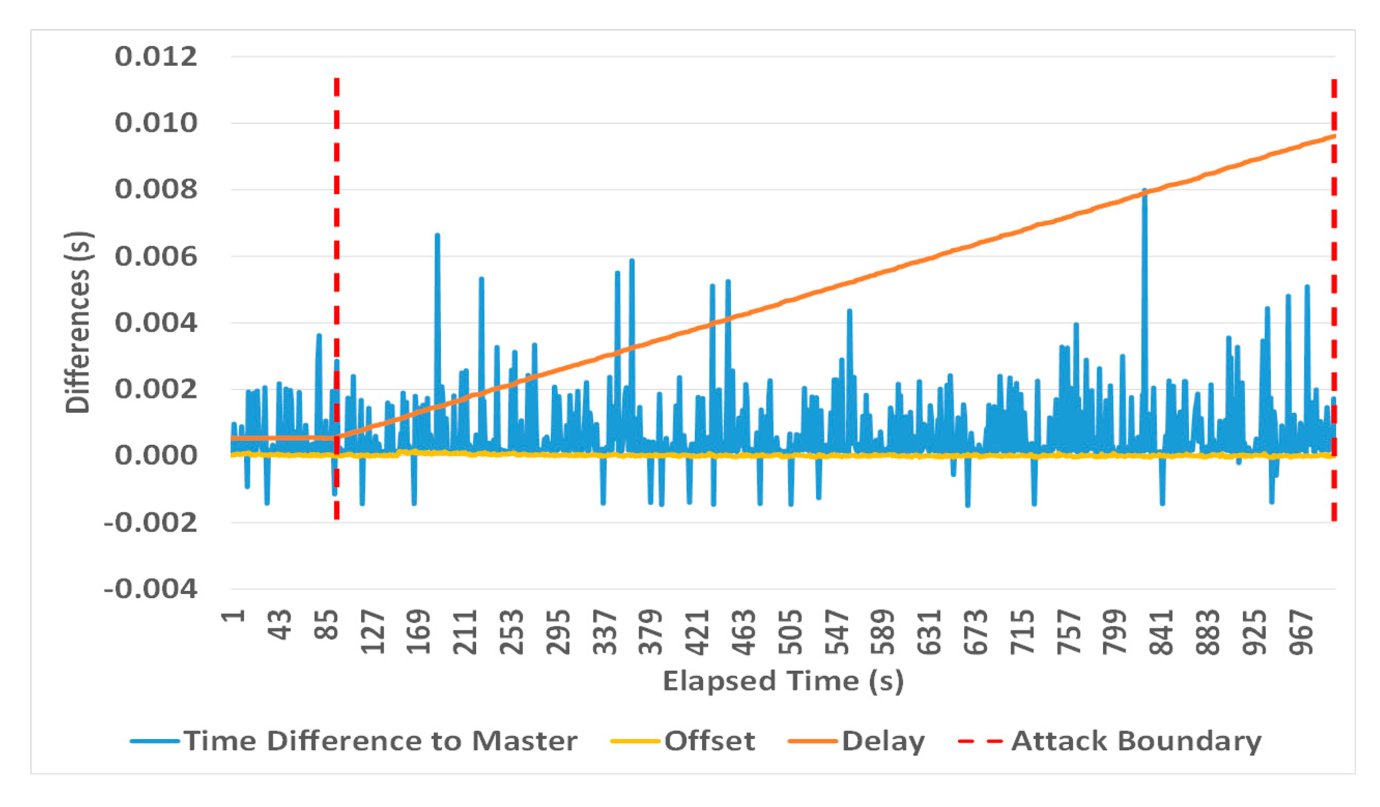
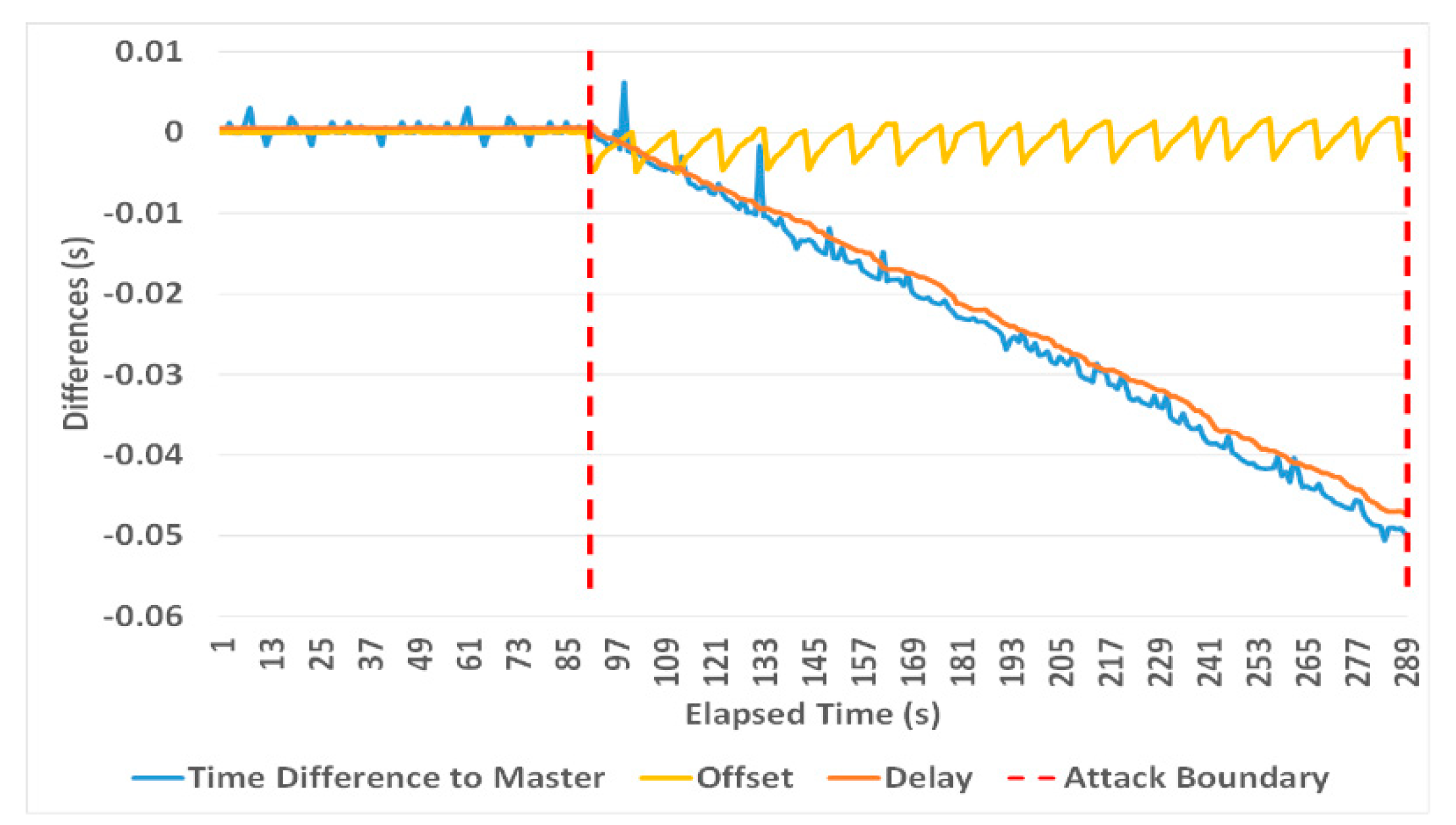
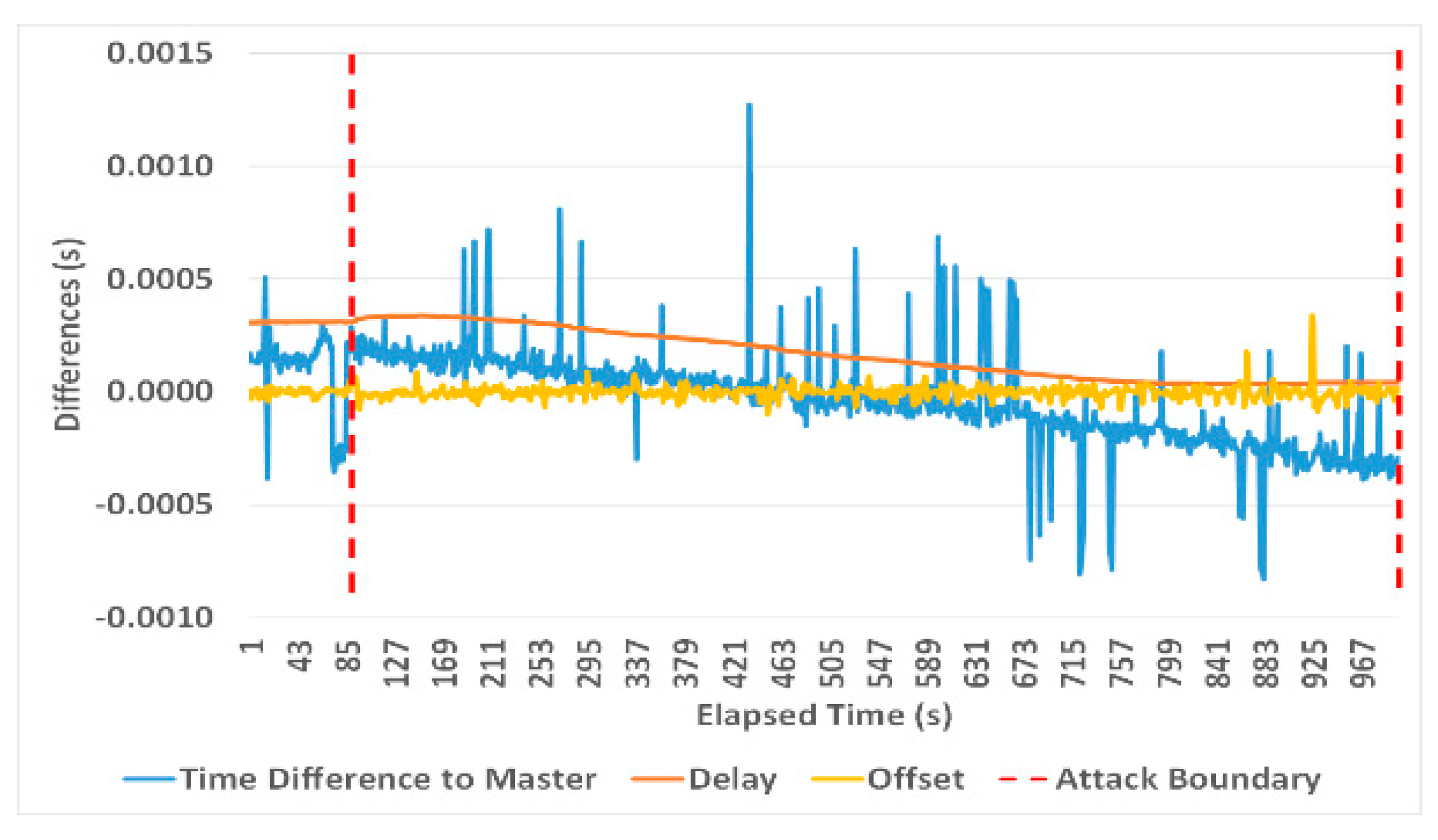
  • In the case of PTPd, introduce an asymmetric/symmetric incremental correctionField offset in the path between the slaves and their master. Here smaller increments result in a small adjustment in the clock frequency and less apparent fluctuations of a slave clock offset and delay value. PTPd is not only vulnerable to both symmetric and asymmetric TC attacks, but its delay values are not correctly reported, making the daemon blind for these attacks.
  • In the case of PTP4l, introduce an incremental asymmetric correctionField offset in the path between the slaves and their master. Here the small increment will not affect the offset values, but the delay values will decrease over time, therefore providing an indicator for this attack.

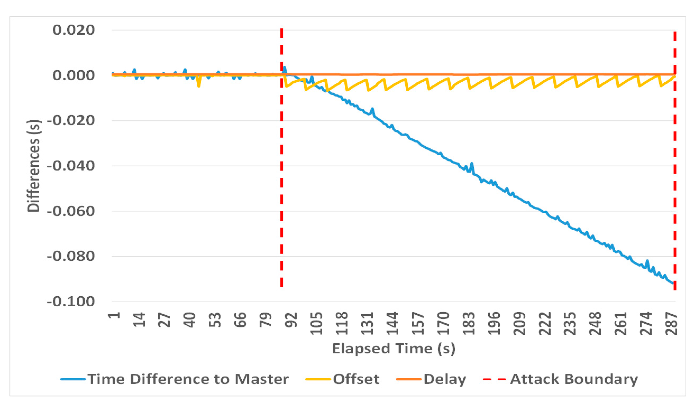
4.2. Attack 2: Time Reference Attack (Compromised TC or GM)

In this attack GM timestamps T1 and T4 are falsified by the MitM device (Figure 28), emulating a manipulation either at source by the GM itself (as a result of a Byzantine attack) or in transit by a manipulated TC. This is done by manipulating the preciseOriginTimestamp of Follow_Up messages (T1) and receiveTimestamp of Delay_Resp messages (T4), whereby T1 and T4 are synchronously and gradually incremented/decremented. This leads to inaccurate offset and mean path delay values as follows:
Offset (PTPd) = (T2 − (T1 ± Err) − (C1 + C2)) − (((T2 − (T1 ± Err) − (C1 + C2)) + ((T4 ± Err) − T3)) − C3)/2
Offset (PTP4l) = (T2 − ((T1 ± Err) + C1 + delayAsymmetry +C2)) − ((T2 − T3) * frequency +
((T4 ± Err) − C3 − ((T1 ± Err) + C1 + delayAsymmetry + C2)))/2
meanPathDelay (PTPd) = (((T2 − (T1 ± Err) − (C1 + C2) + ((T4 ± Err) − T3)) − C3)/2
meanPathDelay (PTP4l) = (((T2 − T3) * ratio) + (((T4 ± Err) − C3) − ((T1 ± Err) + C1 + C2)))/2
where Err represents the manipulated timestamp introduced by an attacker.
Table 6, Figure 29, Figure 30, Figure 31 and Figure 32 show how both PTP daemons behave in the presence of this attack. As already seen in previous experiments, large introduced time errors leave a slave clock slew with the maximum frequency, causing a graduate compensation of offset values as shown in the oscillations in Figure 29 and Figure 31, while small errors have less apparent effects (Figure 30 and Figure 32).
However, this attack does not directly manipulate the delay path and causes only unassuming variations in delay calculations, as shown in Table 6. This makes the time reference attack very devious and hard to detect. It is worth noting that this attack cannot be mitigated via redundant GMs (as the attacker can be positioned in a TC), while infrastructure redundancy can be cancelled if parallel working TCs are manipulated synchronously.

5. Proposed Attack Detection System

In line with the ideas of Annex P Prong D, we propose introducing a monitor node called the trusted supervisor node (TSN) that monitors and analyzes clock offsets and delay values provided by slave devices in a network. The underlying idea is that, while individual slave clocks are intrinsically inaccurate and likely to drift, a group of slaves might show a statistically significant deviation in their offset or delay values if they are exposed to manipulated time packets [7].
Our experiments have already shown that all attacks lead to some increments or oscillations of delay and offset values, respectively, which correlate to the size of the introduced error and the maximum absolute frequency change that can be applied to the clock servo to compensate for local clock errors. Further work will be required to determine if a time-series analysis (conducted by the TSN) of offset and delay values reported by one or more slaves can be used to reliably detect such APTs, therefore complementing recommendations of IEEE 1588 Annex P.

6. Summary and Future Work

This paper provides an experimental validation and characterization on the four most important APTs on PTP networks, comparing the behavior of the two widely used PTP clients PTPd and PTP4l. It presents a testbed and a programmable hardware MitM device that allows conducting a variety of attacks on time synchronization networks.
The experiments show that both clients are vulnerable to the attacks presented and that the resulting time synchronization errors as well as fluctuations of delay and offset values correlate with the chosen attack parameters, i.e., delay or error increments. Their behavior concurs with their specific implementations, which are also outlined and contrasted.
A delayed packet transmission attack can be picked up by both PTP clients by simply observing monotonic increases of delay measurements. A TC (i.e., correctionField) attack, in contrast, can only be reliably detected via delay measurements by PTP4l, while PTPd presents incorrect and unassuming delay values during such an attack. This daemon can also be manipulated via a symmetric correctionField attack, making it therefore even more vulnerable.
In contrast, a time source attack (either implemented in a GM or a TC) does not result in incremental delay calculations, but in oscillating offset values for either daemon, and is, therefore, more difficult to detect. This makes it the most suitable PTP exploit for a high impact APT.
While this paper outlines at attack detection mechanism based on a single monitoring node, further work will be required to determine suitable time-series analysis methods and their limitations with regard to sensitivity and specificity, which depend on the attack type, the duration of the attack, the attack parameters and the number of slaves affected. However, any detection system could be targeted by an APT as well. Therefore, such a solution should be part of a comprehensive defense-in-depth architecture, complemented by other recommendations and best practices as for example outlined by IEEE 1588 Annex P.

Author Contributions

Supervision, M.S.; Writing—original draft, W.A. Both authors have read and agreed to the published version of the manuscript.

Funding

This work was funded by the Technical and Vocational Training Corporation, Saudi Arabia.

Conflicts of Interest

The authors declare no conflict of interest.

References

  1. IEEE Standard for a Precision Clock Synchronization Protocol for Networked Measurement and Control Systems; IEEE Std 1588–2008 (Revision of IEEE Std 1588–2002); IEEE: Piscataway, NJ, USA, 2008; pp. 1–269. [CrossRef]
  2. Estrela, P.V.; Neusüß, S.; Owczarek, W. Using a multi-source NTP watchdog to increase the robustness of PTPv2 in financial industry networks. In Proceedings of the 2014 IEEE International Symposium on Precision Clock Synchronization for Measurement, Control, and Communication (ISPCS), Austin, TX, USA, 21–26 September 2014; pp. 87–92. [Google Scholar]
  3. Mizrahi, T. Time synchronization security using IPsec and MACsec. In Proceedings of the International IEEE Symposium on Precision Clock Synchronization for Measurement Control and Communication, Munich, Germany, 12–16 September 2011; pp. 38–43. [Google Scholar]
  4. Baize, E. Developing Secure Products in the Age of Advanced Persistent Threats. IEEE Secur. Priv. 2012, 10, 88–92. [Google Scholar] [CrossRef]
  5. Langner, R. Stuxnet: Dissecting a cyberwarfare weapon. IEEE Secur. Priv. 2011, 9, 49–51. [Google Scholar] [CrossRef]
  6. Chen, T.; Abu-Nimeh, S. Lessons from stuxnet. Computer 2011, 44, 91–93. [Google Scholar] [CrossRef]
  7. Alghamdi, W.; Schukat, M. Advanced methodologies to deter internal attacks in PTP time synchronization networks. In Proceedings of the 28th Irish Signals and Systems Conference (ISSC), Killarney, Ireland, 20–21 June 2017; pp. 1–6. [Google Scholar]
  8. Itkin, E.; Wool, A. A Security Analysis and Revised Security Extension for the Precision Time Protocol. IEEE Trans. Dependable Secur. Comput. 2020, 17, 22–34. [Google Scholar] [CrossRef] [Green Version]
  9. IEEE Standard for a Precision Clock Synchronization Protocol for Networked Measurement and Control Systems; IEEE Std 1588–2019 (Revision ofIEEE Std 1588–2008); IEEE: Piscataway, NJ, USA, 2020; pp. 1–499.
  10. Shereen, E.; Bitard, F.; Dán, G.; Sel, T.; Fries, S. Next Steps in Security for Time Synchronization: Experiences from implementing IEEE 1588 v2.1. In Proceedings of the 2019 IEEE International Symposium on Precision Clock Synchronization for Measurement, Control, and Communication (ISPCS), Portland, OR, USA, 22–27 September 2019; pp. 1–6. [Google Scholar]
  11. Maftei, D.; Bartos, R.; Noseworthy, B.; Carlin, T. Implementing proposed IEEE 1588 integrated security mechanism. In Proceedings of the 2018 IEEE International Symposium on Precision Clock Synchronization for Measurement, Control, and Communication (ISPCS), Geneva, Switzerland, 30 September–5 October 2018; pp. 1–6. [Google Scholar]
  12. Alghamdi, W.; Schukat, M. Advanced Persistent Threats to Precision Time Protocol Networks: A Vulnerability Analysis. Cybersecur. under review.
  13. Moussa, B.; Kassouf, M.; Hadjidj, R.; Debbabi, M.; Assi, C. An Extension to the Precision Time Protocol (PTP) to Enable the Detection of Cyber Attacks. IEEE Trans. Ind. Inform. 2019, 1. [Google Scholar] [CrossRef]
  14. Han, M.; Crossley, P. Vulnerability of IEEE 1588 under Time Synchronization Attacks. In Proceedings of the 2019 IEEE Power & Energy Society General Meeting (PESGM), Atlanta, GA, USA, 4–8 August 2019; pp. 1–5. [Google Scholar]
  15. Neyer, J.; Gassner, L.; Marinescu, C. Redundant Schemes or How to Counter the Delay Attack on Time Synchronization Protocols. In Proceedings of the 2019 IEEE International Symposium on Precision Clock Synchronization for Measurement, Control, and Communication (ISPCS), Portland, OR, USA, 22–27 September 2019; pp. 1–6. [Google Scholar]
  16. Garner, G.M. IEEE 1588 Version 2. ISPCS Ann. Arbor 2008, 8, 1–89. [Google Scholar]
  17. List of PTP Implementations. Available online: https://en.wikipedia.org/wiki/List_of_PTP_implementations (accessed on 17 April 2020).
  18. The Linux PTP Project. Available online: http://linuxptp.sourceforge.net/ (accessed on 18 April 2020).
  19. Kempen, A.; Kreuzer, S.; Neville, G.; Owczarek, W. Precision Time Protocol Daemon. Available online: https://manpages.debian.org/testing/ptpd/ptpd.8.en.html (accessed on 18 April 2020).
  20. GitHub. PTPd. Available online: https://github.com/ptpd (accessed on 5 May 2020).
  21. Correll, K.; Barendt, N.; Branicky, M. Design Considerations for Software Only Implementations of the IEEE 1588 Precision Time Protocol. Available online: https://citeseerx.ist.psu.edu/viewdoc/download?doi=10.1.1.480.8451&rep=rep1&type=pdf (accessed on 25 August 2020).
  22. GitHub. linuxptp. Available online: https://github.com/openil/linuxptp (accessed on 25 August 2020).
  23. NASPI Time Synchronization Task Force. Time Synchronization in the Electric Power System; Technical Report; North American Synchrophasor Initiative: Washington, DC, USA, 2017. [Google Scholar]
  24. Ullmann, M.; Vögeler, M. Delay attacks—Implication on NTP and PTP time synchronization. In Proceedings of the 2009 International Symposium on Precision Clock Synchronization for Measurement, Control and Communication, Brescia, Italy, 12–16 October 2009; pp. 1–6. [Google Scholar]
  25. Moussa, B.; Debbabi, M.; Assi, C. A Detection and Mitigation Model for PTP Delay Attack in an IEC 61850 Substation. IEEE Trans. Smart Grid 2018, 9, 3954–3965. [Google Scholar] [CrossRef]
  26. Mizrahi, T. Security Requirements of Time Protocols in Packet Switched Networks; Internet Engineering Task Force (IETF): Fremont, CA, USA, 2014. [Google Scholar]
  27. Narula, L.; Humphreys, T.E. Requirements for Secure Clock Synchronization. IEEE J. Sel. Top. Signal Process. 2018, 12, 749–762. [Google Scholar] [CrossRef]
  28. Koskiahde, T.; Kujala, J. PTP monitoring in redundant network. In Proceedings of the 2016 IEEE International Symposium on Precision Clock Synchronization for Measurement, Control, and Communication (ISPCS), Stockholm, Sweden, 4–9 September 2016; pp. 1–5. [Google Scholar]
  29. Dalmas, M.; Rachadel, H.; Silvano, G.; Dutra, C. Improving PTP robustness to the byzantine failure. In Proceedings of the 2015 IEEE International Symposium on Precision Clock Synchronization for Measurement, Control, and Communication (ISPCS), Beijing, China, 11–16 October 2015; pp. 111–114. [Google Scholar]
  30. Shpiner, A.; Revah, Y.; Mizrahi, T. Multi-path Time Protocols. In Proceedings of the 2013 IEEE International Symposium on Precision Clock Synchronization for Measurement, Control and Communication (ISPCS), Lemgo, Germany, 22–27 September 2013; pp. 1–6. [Google Scholar]
  31. IEEE Draft Standard for a Precision Clock Synchronization Protocol for Networked Measurement and Control Systems; IEEE: Piscataway, NJ, USA, 2019; pp. 1–535.
  32. Girela-López, F.; López-Jiménez, J.; Jiménez-López, M.; Rodríguez, R.; Ros, E.; Díaz, J. IEEE 1588 high accuracy default profile: Applications and challenges. IEEE Access 2020, 8, 45211–45220. [Google Scholar] [CrossRef]
  33. Shannon, J.; Melvin, H.; Ruzzelli, A.G. Dynamic flooding time synchronisation protocol for WSNs. In Proceedings of the 2012 IEEE Global Communications Conference (GLOBECOM), Anaheim, CA, USA, 3–7 December 2012; pp. 365–371. [Google Scholar]
  34. ITU. G.8275.2: Precision Time Protocol Telecom Profile for Time/Phase Synchronization with Partial Timing Support from the Network. Available online: https://www.itu.int/rec/T-REC-G.8275.2-202003-I/en (accessed on 21 June 2020).
  35. ST 2059-2:2015—SMPTE Standard—SMPTE Profile for Use of IEEE-1588 Precision Time Protocol in Professional Broadcast Applications; ST 2059-2:2015; The Society of Motion Picture and Television Engineers (SMPTE): White Plains, NY, USA, 2015; pp. 1–19. ISBN 9781614828648.
Figure 1. Precision time protocol (PTP) timestamps and time synchronization messages in transparent clock end–to-end mode.
Electronics 09 01398 g001
Figure 2. Offset and delay range of two PTP daemons running on the same machine.
Electronics 09 01398 g002
Figure 3. Manipulated residence time in transparent clock.
Electronics 09 01398 g003
Figure 4. The PTP testbed.
Electronics 09 01398 g004
Figure 5. Galileo clock in free-running mode.
Electronics 09 01398 g005
Figure 6. Raspberry Pi clock in free-running mode.
Electronics 09 01398 g006
Figure 7. The packet propagation attack.
Electronics 09 01398 g007
Figure 8. A single asymmetric delay increment of 20 ms (PTP4l).
Electronics 09 01398 g008
Figure 9. A single asymmetric delay increment of 20 ms (PTPd).
Electronics 09 01398 g009
Figure 10. Asymmetric delay attack with a 5 ms increment every second (PTP4l).
Electronics 09 01398 g010
Figure 11. Asymmetric delay attack with a 5 ms increment every second (PTPd).
Electronics 09 01398 g011
Figure 12. Asymmetric delay attack with a 10 µs increment every second (PTP4l).
Electronics 09 01398 g012
Figure 13. Asymmetric delay attack with a 10 µs increment every second (PTPd).
Electronics 09 01398 g013
Figure 14. A single symmetric delay increment of 20 ms (PTP4l).
Electronics 09 01398 g014
Figure 15. A single symmetric delay increment of 20 ms (PTPd).
Electronics 09 01398 g015
Figure 16. Symmetric delay attack with a 10 µs increment every second (PTP4l).
Electronics 09 01398 g016
Figure 17. Symmetric delay attack with a 10 µs increment every second (PTPd).
Electronics 09 01398 g017
Figure 18. Symmetric delay attack with a 5 ms increment every second (PTP4l).
Electronics 09 01398 g018
Figure 19. Symmetric delay attack with a 5 ms increment every second (PTPd).
Electronics 09 01398 g019
Figure 20. Asymmetric TC manipulation with a 5 ms increment every 10 s (PTP4l).
Electronics 09 01398 g020
Figure 21. Asymmetric TC manipulation with a 5 ms increment every 10 s (PTPd).
Electronics 09 01398 g021
Figure 22. Asymmetric TC manipulation with a 10 µs increment every 10 s (PTP4l).
Electronics 09 01398 g022
Figure 23. Asymmetric TC manipulation with a 10 µs increment every 10 s (PTPd).
Electronics 09 01398 g023
Figure 24. Symmetric TC manipulation with a 5 ms increment every 10 s (PTP4l).
Electronics 09 01398 g024
Figure 25. Symmetric TC manipulation with a 5 ms increment every 10 s (PTPd).
Electronics 09 01398 g025
Figure 26. Symmetric TC manipulation with a 10 µs increment every 10 s (PTP4l).
Electronics 09 01398 g026
Figure 27. Symmetric TC manipulation with a 10 µs increment every 10 s (PTPd).
Electronics 09 01398 g027
Figure 28. Grandmaster (GM) attack setup.
Electronics 09 01398 g028
Figure 29. GM timestamp increment of 5 ms every 10 s (PTP4l).
Electronics 09 01398 g029
Figure 30. GM timestamp increment of 10 µs every 10 s (PTP4l).
Electronics 09 01398 g030
Figure 31. GM timestamp increment of 5 ms every 10 s (PTPd).
Electronics 09 01398 g031
Figure 32. GM timestamp increment of 10 µs every 10 s (PTPd).
Electronics 09 01398 g032
Table 1. Offset/Delay statistics.
ConfigurationClock Characteristics after 20 min
OffsetMean Path Delay
Average (µs)Standard Deviation (µs)Average (µs)Standard Deviation (µs)
Galileo without MitM−0.066154243
Galileo with MitM−0.031305376
Raspberry without MitM0.12581691
Raspberry with MitM0.065142802
Table 2. Summary of investigated attacks.
Attack TypeTypical Attacker Location
Delayed packet transmissionSwitch
correctionField manipulationTC
GM timestamp manipulationTC
Byzantine attackGM
Table 3. Experiments parameters and settings.
ParameterSettingComment
Delay mechanismEnd-to-EndThe ordinary switches used do not support peer delay mechanism
Operation ModeTwo-StepSlave NIC does not support HW timestamping
IP protocolVersion 4-
Log Sync Interval0The master sends a Sync message every 20 s
Log Announce Interval1The master sends an Announce message each 21 s
Announce receipt timeout3After 3 unsuccessful announce intervals a slave clock will change into free-running mode
Log delay request interval0The slave sends a new Delay_Req message every 20 s
Clock Frequency512 ppmMaximum absolute frequency change that can be applied to the clock servo
Clock AdjustmentenabledSlave clock update enabled
Clock Reset & Step threshold (PTP4l)On start-upReset the clock only at the beginning of the synchronization
Clock Reset & Step threshold (PTPd)offset >1 sReset the clock only if the offset from the master is greater than one second
Table 4. Experiments and delay attack parameters.
Experiment NoAttack Parameters
Delay Increment between CyclesIntervalDuration of AttackDelay TypePTP DaemonAccumulated Slave Clock DriftOffset AverageDelay Average
15 ms1 s200 sAsymmetricPTP4l93 ms226 ms234 ms
PTPd101 ms164 ms74 ms
SymmetricPTP4l84 ms24 ms432 ms
PTPd61 ms51 ms187 ms
210 µs1 s910 sAsymmetricPTP4l5 ms8.6 µs2.8 ms
PTPd5 ms13 µs1 ms
SymmetricPTP4l013 µs5 ms
PTPd0−3.3 µs2.4 ms
320 ms (once-off increment)-910 sAsymmetricPTP4l10 ms135 µs10 ms
PTPd10 ms75 µs9 ms
SymmetricPTP4l0114 µs20 ms
PTPd0268 µs17 ms
Table 5. Experiments and correctionField manipulation parameters.
Experiment NoAttack Parameters
Correction Field Timestamp Increment between CyclesIntervalDuration of AttackIncrement TypePTP DaemonAccumulated Slave Clock DriftOffset AverageDelay Average
15 ms10 s200 sAsymmetricPTP4l−50 ms−1 ms−22.8 ms
PTPd−98 ms−2.2 ms116 µs
SymmetricPTP4l−3 ms−0.807 µs−48 ms
PTPd−75 ms−2.3 ms28 µs
210 µs10 s910 sAsymmetricPTP4l−230 µs6 µs388 µs
PTPd−326 µs−0.802 µs163 µs
SymmetricPTP4l≈ 0−0.077 µs108.5 µs
PTPd−500 µs−0.822114 µs
Table 6. Experiments and timestamp manipulation parameters.
Experiment NoAttack Parameters
Grandmaster Timestamp Increment between CyclesIntervalDuration of AttackIncrement TypePTP DaemonAccumulated Slave Clock DriftOffset AverageDelay Average
15 ms10 s200 sSymmetricPTP4l−92 ms−3.2 ms452 µ
PTPd−101 ms−2.3 ms310 µ
210 µs10 s910 sPTP4l−910 µ−0.913 µ583 µ
PTPd−910 µ−16 µ315 µ

