Multiband Dual-Meander Line Antenna for Body-Centric Networks’ Biomedical Applications by Using UMC 180 nm


Abstract
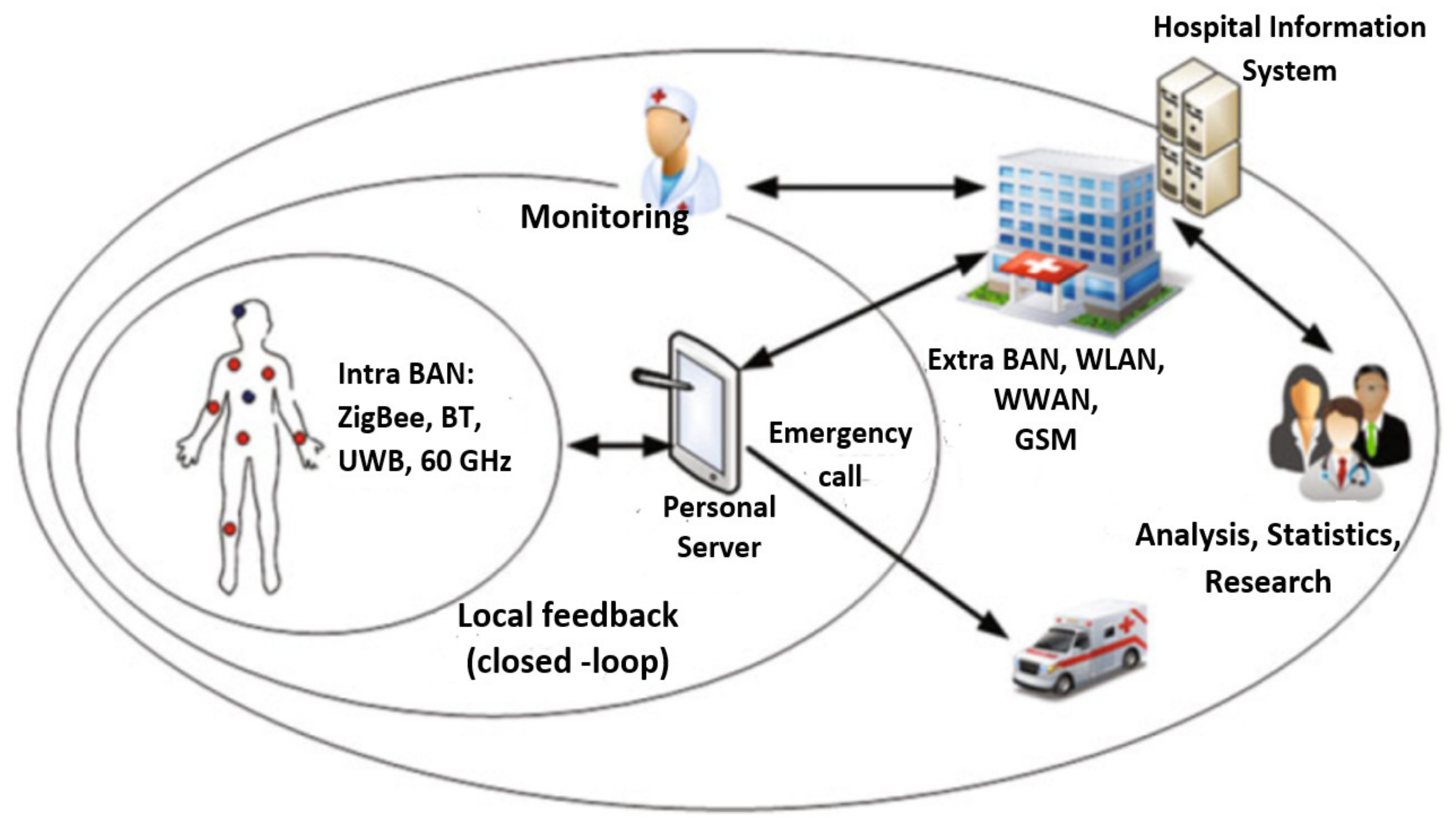
:1. Introduction
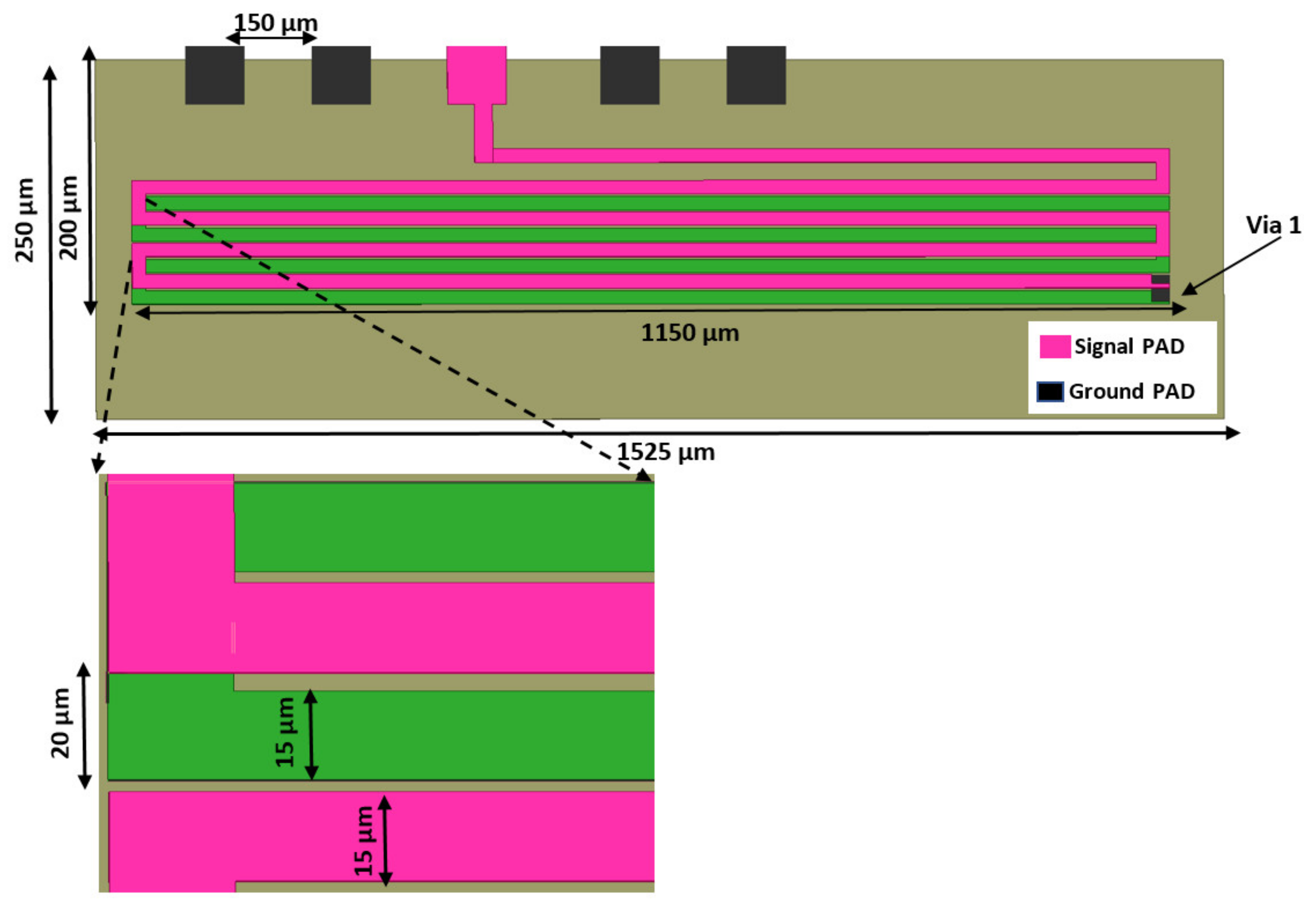
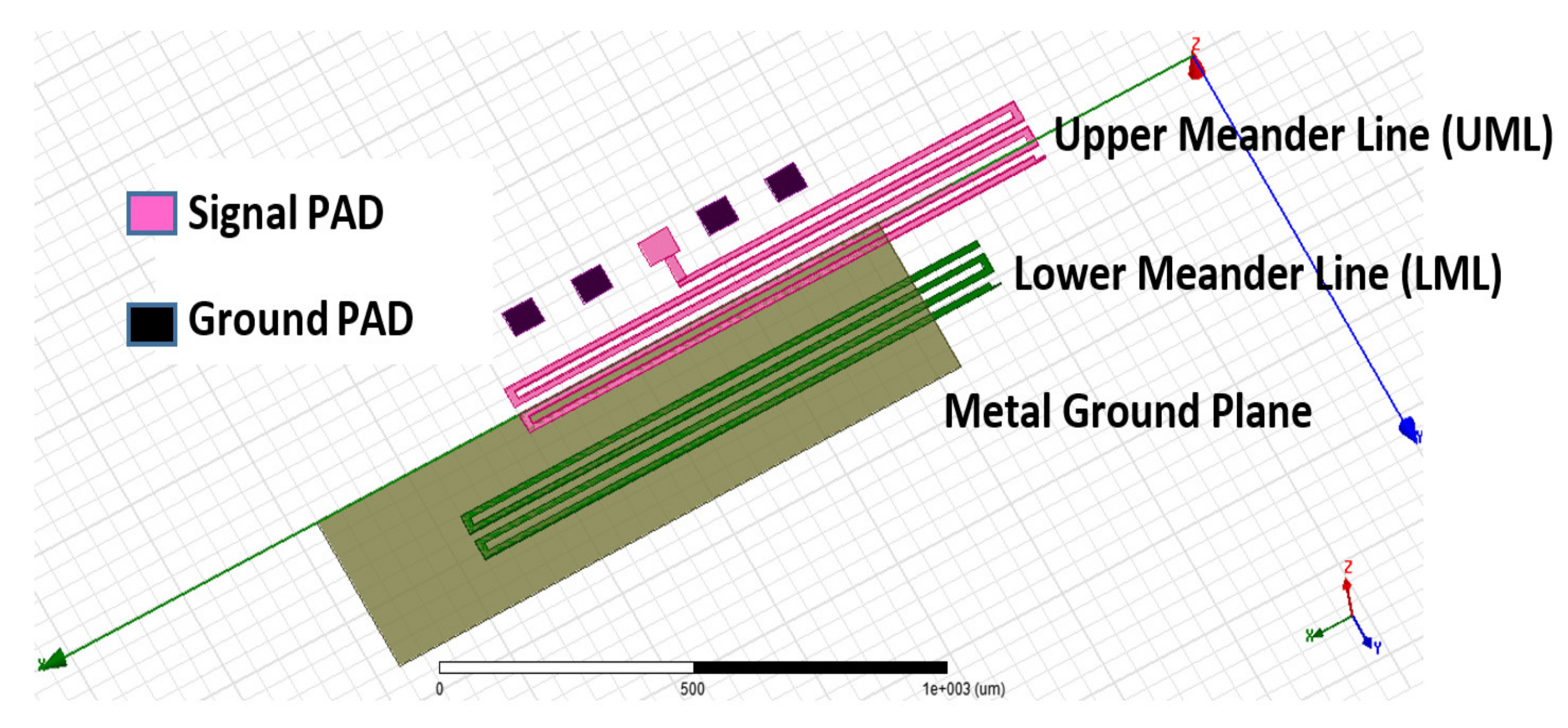
2. Antenna Configuration and Design
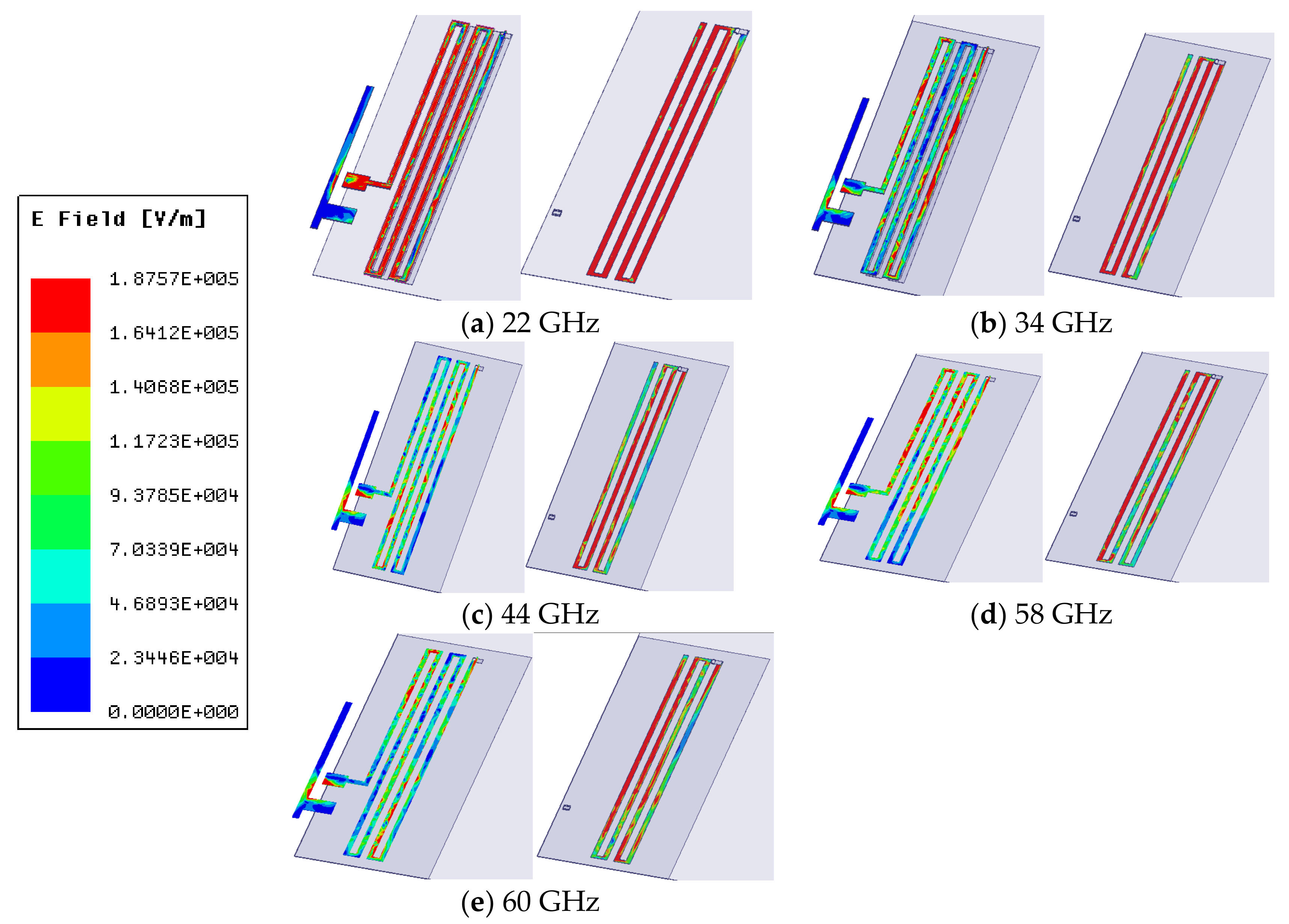
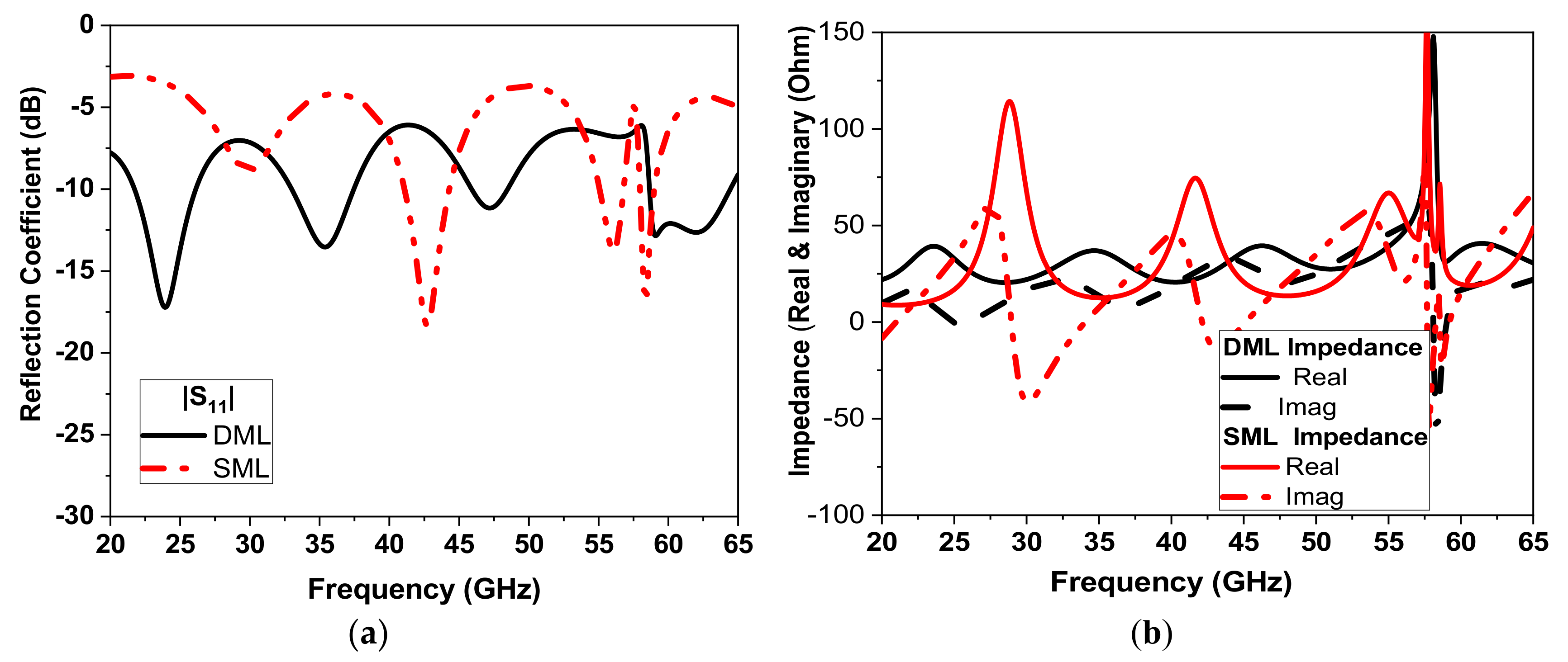
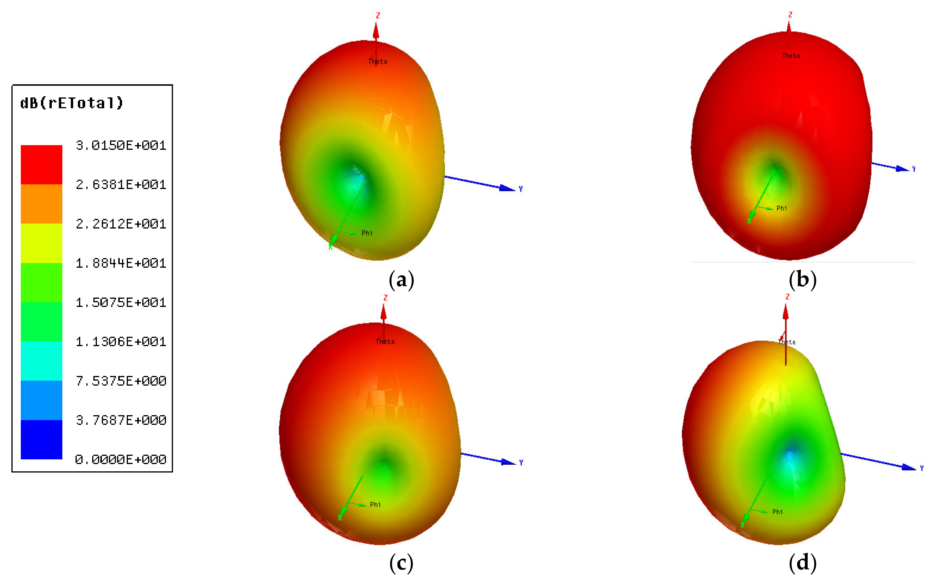
3. Antenna Performance Results
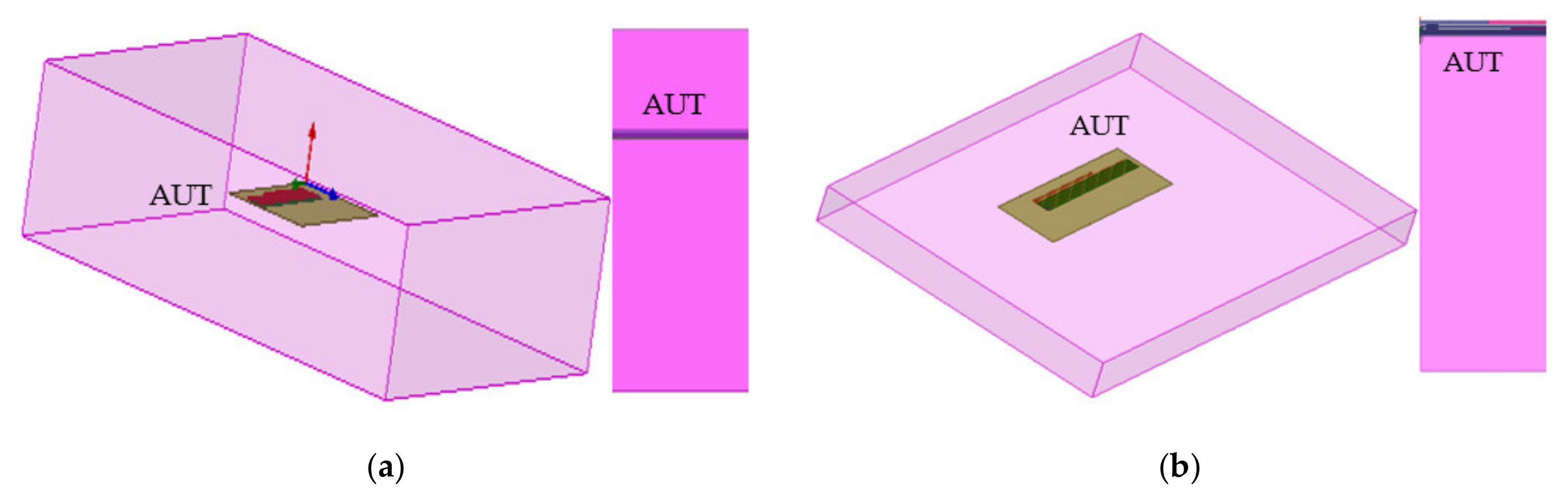
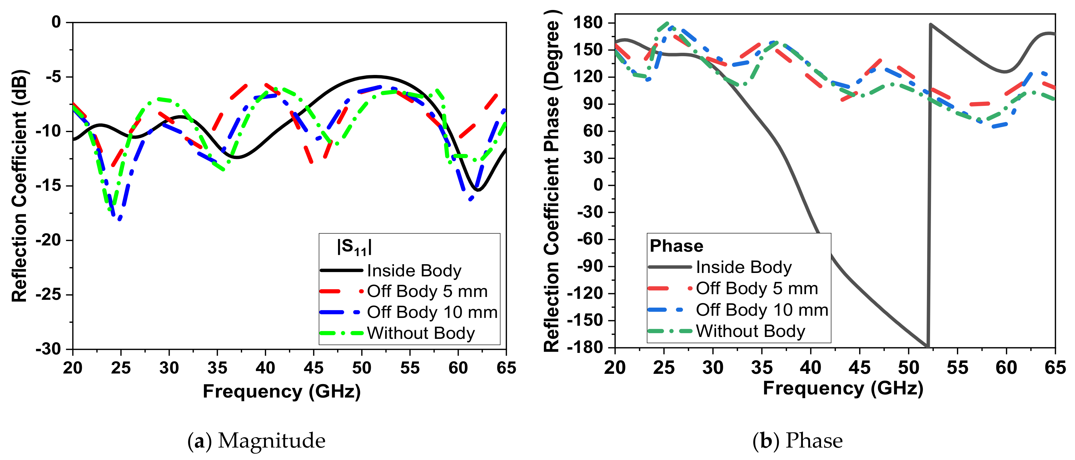
4. Analysis of Human-Body Effect
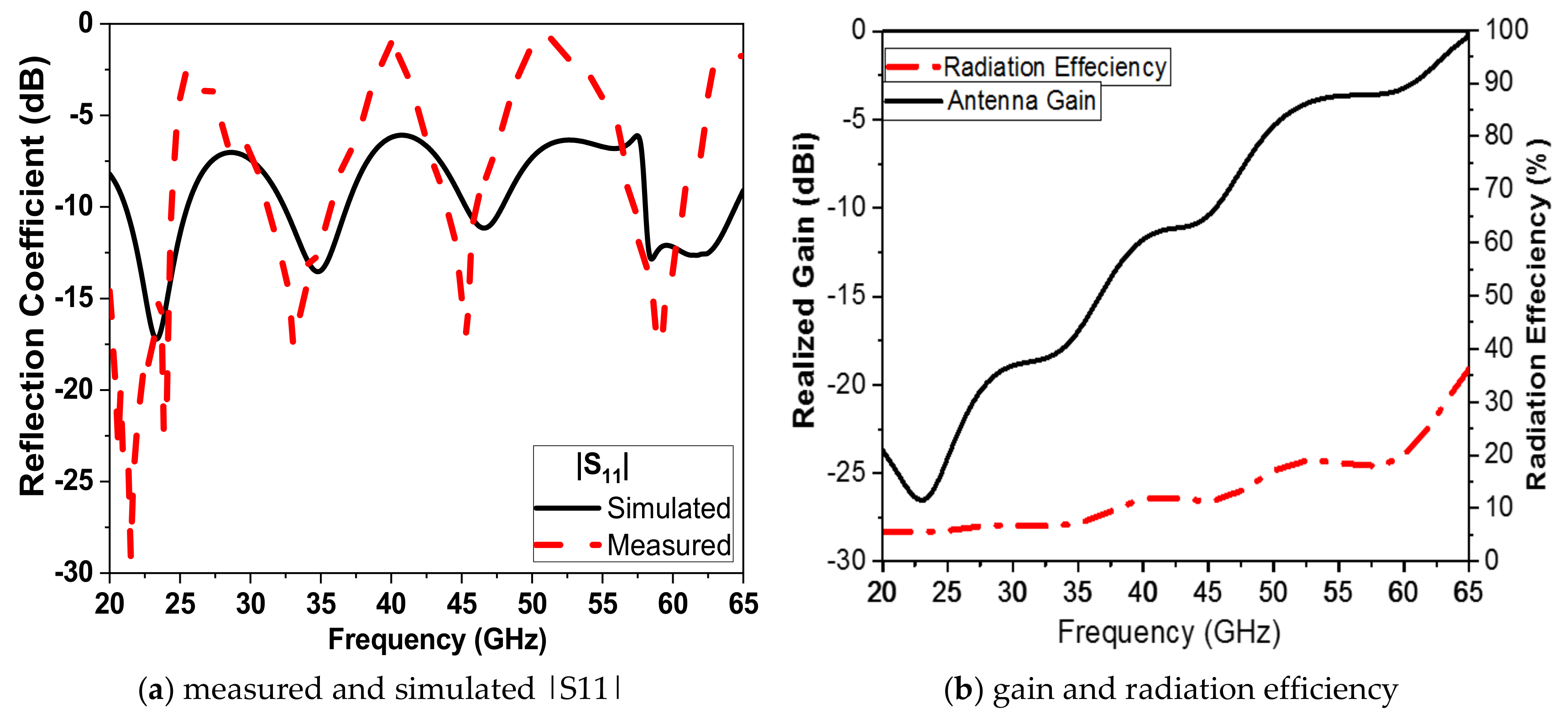
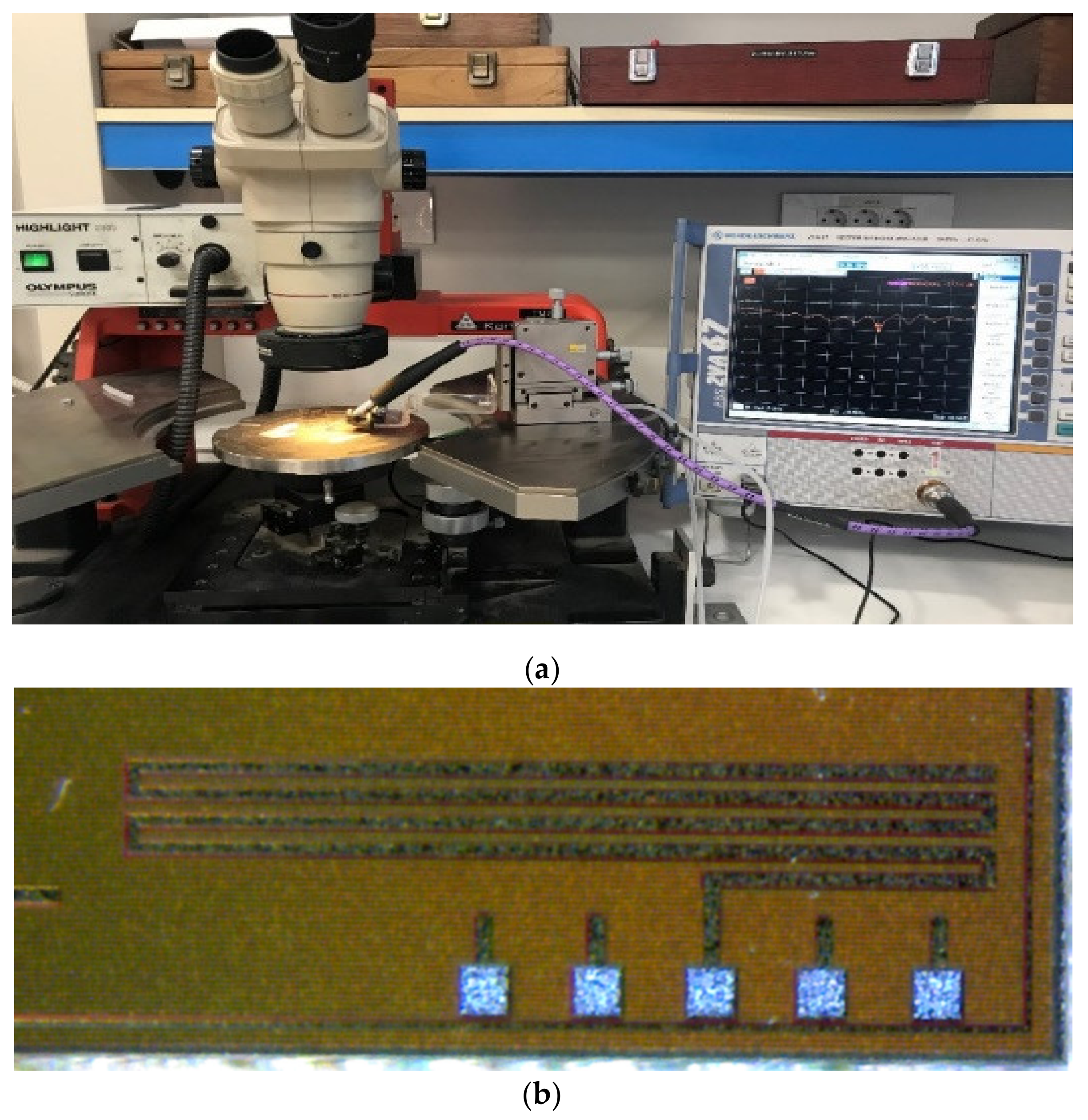
5. Measurement of the Proposed Antenna
6. Conclusions
Author Contributions
Funding
Conflicts of Interest
References
- Mehmet, R.Y. Ultra-Wideband and 60 GHz Communications for Biomedical Applications; Springer Science Business Media: New York, NY, USA, 2014. [Google Scholar]
- Abbasi, Q.H.; Ur-Rehman, M.; Qaraqe, K.; Alomainy, A. Advances in Body-Centric Wireless Communication: Applications and State of the Art; The IET: Stevenage, UK, 2016. [Google Scholar]
- Ali, M.; Shawkey, H.; Zekry, A.; Sawan, M. One Mbps 1 nJ/b 3.5–4 GHz Fully Integrated FM-UWB Transmitter for WBAN Applications. IEEE Trans. Circuits Syst. I: Regul. Pap. 2018, 65, 2005–2014. [Google Scholar] [CrossRef]
- Hall, P. Advances in Antennas and Propagation for Body Centric Wireless Communications. In Proceedings of the Fourth European Conference on Antennas and Propagation, Barcelona, Spain, 12–16 April 2010. [Google Scholar]
- Taylor, W.; Shah, S.A.; Dastoor, K.; Qamar, A.Z.; Abbasi, H.; Imran, M.A. An intelligent non-invasive real-time human activity recognition system for next-generation healthcare. Sensors 2020, 20, 2653. [Google Scholar] [CrossRef] [PubMed]
- Fan, D.; Ren, A.; Zhao, N.; Yang, X.; Zhang, Z.; Aziz, S.; Shah, F.H.; Abbasi, Q.H. Breathing rhythm analysis in body centric networks. IEEE Access 2018, 6, 32507–32513. [Google Scholar] [CrossRef]
- Lin, X.; Seet, B.; Joseph, F. Fabric antenna with body temperature sensing for BAN applications over 5G wireless systems. In Proceedings of the 2015 9th International Conference on Sensing Technology (ICST), Auckland, New Zealand, 8–10 December 2015; pp. 591–595. [Google Scholar] [CrossRef]
- Sodhro, H.; Shah, M.A. Role of 5G in medical health. In Proceedings of the 2017 International Conference on Innovations in Electrical Engineering and Computational Technologies (ICIEECT), Karachi, Pakistan, 5–7 April 2017; pp. 1–5. [Google Scholar]
- Lal, N.; Kumar, A. E-health application over 5G using Content-Centric networking (CCN). In Proceedings of the International Conference on IoT and Application (ICIOT), Navaratnam, India, 19–20 May 2017; pp. 1–5. [Google Scholar]
- Huang, J.; Xing, C.; Wang, C. Simultaneous wireless information and power transfer: Technologies, applications, and research challenges. IEEE Commun. Mag. 2017, 55, 26–32. [Google Scholar] [CrossRef]
- Wang, X.; Cenk, M.; Gursoy, I. Simultaneous wireless information and power transfer in UAV-assisted cellular IoT networks. In Proceedings of the 2020 IEEE 17th Annual Consumer Communications & Networking Conference (CCNC), Las Vegas, NV, USA, 10–13 January 2020. [Google Scholar]
- Zhao, N.; Zhang, Z.; Rehman, M.U.; Ren, A.; Yang, X.; Zhao, J.; Zhao, W.; Dong, B. Authentication in millimeter-wave body-centric networks through wireless channel characterization. IEEE Trans. Antennas Propag. 2017, 65, 6616–6623. [Google Scholar] [CrossRef] [Green Version]
- Mavromoustakis, C.X.; Mastorakis, G.; Batalla, J.M. Internet of Things (IoT) in 5G Mobile Technologies; Springer International Publishing: Geneva, Switzerland, 2016. [Google Scholar]
- Ladan, S.; Guntupalli, A.B.; Wu, K. A high-efficiency 24 GHz rectenna development towards millimeter-wave energy harvesting and wireless power transmission. IEEE Trans. Cir. Syst. I Regul. Pap. 2014, 61, 3358–3366. [Google Scholar] [CrossRef]
- Shinohara, N.; Nishikawa, K.; Seki, T.; Hiraga, K. Development of 24 GHz rectennas for fixed wireless access. In Proceedings of the URSI General Assembly and Scientific Symposium, Istanbul, Turkey, 13–20 August 2011; pp. 1–4. [Google Scholar]
- Mizojiri, S.; Shimamura, K. Wireless power transfer via sub terahertz-wave. Appl. Sci. 2018, 8, 2653. [Google Scholar] [CrossRef] [Green Version]
- Chiou, H.-K.; Chen, I.-S. High efficiency dual-band on-chip rectenna for 35- and 94-GHz wireless power transmission in 0.13-μm CMOS Technology. IEEE Trans. Microw. Theory Tech. 2010, 58, 3598–3606. [Google Scholar]
- Tabesh, M.; Dolatsha, N.; Arbabian, A.; Niknejad, A.M. A Power-harvesting pad-less millimeter-sized radio. IEEE J. Solid State Circuits Jsscs 2015, 50, 962–977. [Google Scholar] [CrossRef]
- Huang, J.; Wu, J.; Chiou, Y.; Jou, C. A 24/60 GHz dual-band millimeter-wave on-chip monopole antenna fabricated with a 0.13-μm CMOS Technology. In Proceedings of the IEEE International Workshop on Antenna Technology, Santa Monica, CA, USA, 2–4 March 2009. [Google Scholar]
- Song, Y.; Xu, Q.; Tian, Y.; Yang, J.; Wu, Y.; Tang, X.; Kang, K. An on chip frequency-reconfigurable antenna For Q-band broadband applications. IEEE Antennas Wirel. Propag. Lett. 2017, 16, 2232–2235. [Google Scholar] [CrossRef]
- Ur-Rehman, M.; Adekanye, M.; Chattha, H.T. Tri-band millimetre-wave antenna for body-centric networks. Nano Commun. Netw. 2018, 18, 72–81. [Google Scholar] [CrossRef] [Green Version]
- Taeb, A.; Gigoyan, S.; Naeini, S.S. Millimetre-wave waveguide reflectometers for early detection of skin cancer. IET Microw. Antennas Propag. 2013, 7, 1182–1186. [Google Scholar] [CrossRef]
- Porter, E.; Bahrami, H.; Santorelli, A.; Gosselin, B.; Rusch, L.A.; Popović, M. A Wearable microwave antenna array for time-domain breast tumor screening. IEEE Trans. Med. Imaging 2016, 35, 1501–1509. [Google Scholar] [CrossRef] [PubMed] [Green Version]
- Gabriel, S.; Lau, R.W.; Gabriel, C. The dielectric properties of biological tissues: II. measurements in the frequency range 10 Hz to 20 GHz. Phys. Med. Biol. 1996, 41, 2251–2269. [Google Scholar] [CrossRef] [Green Version]
- Dielectric Properties, ITIS Website. Available online: http://http://www.itis.ethz.ch/virtualpopulation/tissue-properties/database/dielectric-properties (accessed on 10 August 2020).
- Elsheakh, D.N.; Iskander, M.F. Circularly polarized tri-band printed quasi-Yagi antenna for millimeter-wave applications. Int. J. Antennas Propag. 2015, 15, 1–10. [Google Scholar] [CrossRef]
- Cao, C.; Ding, Y.; Yang, X.; Lin, J.; Verma, A.; Lin, J.; Martin, F.; Kenneth, K.O. A 24-GHz Transmitter with an On-chip Antenna in 130-nm CMOS. IEEE Trans. Antenna Propag. 2008, 56, 1394–1402. [Google Scholar]
- Wang, L.; Sun, W.Z. A 60-GHZ differential-fed circularly polarized on-chip antenna based on 0.18-m COMS technology with AMC structure. In Proceedings of the IET International Radar Conference, Hangzhou, China, 14–16 October 2015; pp. 1–4. [Google Scholar]
- Khan, M.S.; Tahir, F.A.; Cheema, H.M. Design of bowtie-slot on chip antenna backed with E-shaped FSS at 94 GHz. In Proceedings of the 2016 10th European Conference on Antennas and Propagation (EU CAP), Davos, Switzerland, 10–15 April 2016; pp. 1–3. [Google Scholar]
- Song, Y.; Wu, Y.; Yang, J.; Kang, K. The design of a high gain on-chip antenna for SoC application. In Proceedings of the 2015 IEEE MTT-S International Microwave Workshop Series on Advanced Materials and Processes for RF and THz Applications (IMWS-AMP), Suzhou, China, 1–3 July 2015; pp. 1–3. [Google Scholar]


| Plane | 22 GHz | 34 GHz | 45 GHz | 58 GHz |
|---|---|---|---|---|
| φ = 0° |  | 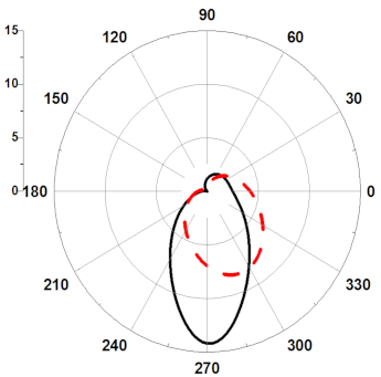 |  | 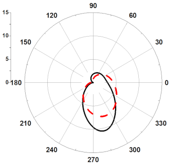 |
| Ɵ = 90° |  | 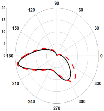 |  | 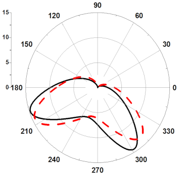 |
 without human body,
  with human body.
| Reference | |||||||
|---|---|---|---|---|---|---|---|
| [27] | [19] | [20] | [28] | [29] | [30] | This Work | |
| Freq. GHz | 24 | 24/60 | 40–50 | 60 | 94 | 67 | 22/34/44/58 |
| Gain dBi | −8 | −9/−1 | −0.8 to 3.3 | −3.2 | Rehman-2.71 | −8 | −20/−15/−10/−1 |
| BW GHz | - | 0.18/0.7 | 5.3 | 5.5 | 15 | 4 | 5/6/4/8 |
| Area mm2 | 3 mm length | 0.794 | 1.87 | 2.25 | 0.22 | 0.875 | 0.23 mm2 |
| Tech. | 0.13 μm CMOS | 0.13 μm CMOS | 0.18 μm CMOS | 0.18 μm CMOS | IHP 0.13 μm Bi-CMOS | 0.18 μm CMOS | 0.18 μm CMOS |
© 2020 by the authors. Licensee MDPI, Basel, Switzerland. This article is an open access article distributed under the terms and conditions of the Creative Commons Attribution (CC BY) license (http://creativecommons.org/licenses/by/4.0/).
Share and Cite
Shawkey, H.; Elsheakh, D. Multiband Dual-Meander Line Antenna for Body-Centric Networks’ Biomedical Applications by Using UMC 180 nm. Electronics 2020, 9, 1350. https://doi.org/10.3390/electronics9091350
Shawkey H, Elsheakh D. Multiband Dual-Meander Line Antenna for Body-Centric Networks’ Biomedical Applications by Using UMC 180 nm. Electronics. 2020; 9(9):1350. https://doi.org/10.3390/electronics9091350
Chicago/Turabian StyleShawkey, Heba, and Dalia Elsheakh. 2020. "Multiband Dual-Meander Line Antenna for Body-Centric Networks’ Biomedical Applications by Using UMC 180 nm" Electronics 9, no. 9: 1350. https://doi.org/10.3390/electronics9091350
APA StyleShawkey, H., & Elsheakh, D. (2020). Multiband Dual-Meander Line Antenna for Body-Centric Networks’ Biomedical Applications by Using UMC 180 nm. Electronics, 9(9), 1350. https://doi.org/10.3390/electronics9091350