Article

Low-Complexity Multi-User Parameterized Beamforming in Massive MIMO Systems

Department of Electrical and Computer Engineering, Institute of New Media and Communications, Seoul National University, Seoul 08826, Korea
*
Author to whom correspondence should be addressed.
Electronics 2020, 9(6), 882; https://doi.org/10.3390/electronics9060882
Submission received: 20 April 2020 / Revised: 14 May 2020 / Accepted: 21 May 2020 / Published: 26 May 2020
(This article belongs to the Special Issue Massive MIMO for 5G)

Abstract

:
In this paper, we design a complexity-reduced transmission scheme in massive antenna environments. To reduce the implementation complexity for the generation of beam weight, we design a multi-user parameterized beamforming (MUPB) scheme that can control the beam direction using a single parameter with combined use of maximum ratio transmission and partial zero-forcing scheme that partially nulls out interference. We design the MUPB to maximize the signal-to-leakage plus noise ratio (SLNR). To further reduce the implementation complexity, we optimize the MUPB based on approximated SLNR instead of accurate SLNR. Finally, the performance of the proposed MUPB is verified by computer simulation.

1. Introduction

The use of massive multi-input multi-output (m-MIMO) techniques has widely been applied to advanced wireless communication systems [1,2,3]. A base station (BS) equipped with an m-MIMO configuration can serve a large number of users by means of beamforming. The channel becomes asymptotically orthogonal to each other as the number of antennas increases to infinity [4]. In this case, we may achieve optimum performance by using a maximum ratio transmission (MRT) technique with affordable implementation complexity. However, the MRT may suffer from inter-user interference in practical m-MIMO operation environments mainly due to the presence of insufficient orthogonality [5].
The use of zero-forcing (ZF) beamforming can be a practical choice in m-MIMO environments since it may easily null out inter-user interference [6,7,8]. However, it may require large computational complexity for the generation of beam weight in m-MIMO environments. A number of approaches have been proposed to reduce the computational complexity of ZF [9,10,11,12,13,14,15,16,17]. The complexity can be reduced by using an approximation technique such as Neumann series (NS) expansion [9], truncated polynomial expansion (TPE) [10], Kapteyn series expansion [11], and eigen-based approximation [12]. The complexity can also be reduced by using an iteration method such as Gauss-Seidel (GS) method [13], symmetric successive over relaxation (SSOR) method [14], Newton iteration (NI) method [15], Jacobi algorithm [16], and weighted two stage (WTS) method [17]. These approaches may somewhat reduce the computational complexity, but they may suffer from performance degradation associated with the approximation in matrix inversion. Moreover, when they are applied to a large number of users, they may not be effective since their complexity increases in proportion to the number of users.
The complexity for the generation of ZF beam weight can be reduced as the dimension of nulling subspace decreases [18,19]. The lower the dimension of nulling subspace, the larger the spatial degrees of freedom (DoF), making it possible to enhance desired signal power while marginally increasing interference. It may be effective in low signal-to-noise ratio (SNR) environments (e.g., cell boundary region). A ZF technique can decrease the dimension of nulling subspace by only considering intra-cell interfering channel [18]. A cell-edge-aware (CEA)-ZF technique can selectively null out interference to inter-cell users based on the path loss between the BS and inter-cell users [19]. However, these approaches may not be effective in low SNR environments since they decrease the dimension of nulling subspace without careful consideration of transmission environments.
In this paper, we design a complexity-reduced multi-user beamforming scheme in m-MIMO environments. The beam weight can be determined to maximize the signal-to-interference plus noise ratio (SINR), which may require large computational complexity mainly due to non-convexity property of the SINR [20,21]. Instead, we consider the signal-to-leakage plus noise ratio (SLNR) for the generation of beam weight. The SLNR is defined by the ratio between the desired signal power to a target user and the total interference power to other users (i.e., the leakage power) plus noise. The Max SLNR technique maximizes the SLNR by applying Rayleigh–Ritz quotient theorem [22,23]. However, it may require computational complexity in cubic proportion to the number of antennas, which may be unaffordable in m-MIMO environments. To further reduce the computational complexity, we employ a parameterized beamforming (PB) technique that employs MRT and ZF beamforming techniques, where large-scale beam weight can be determined by a single parameter [24,25]. As the number of users increases, the ZF may experience the presence of insufficient spatial DoF, yielding poor performance of PB in multi-user environments. To alleviate this problem, we consider the use of a partial ZF (PZF) beamforming technique that selectively nulls out interference, making it possible to reduce the dimension of nulling subspace (i.e., to exploit more spatial DoF). We may alleviate the performance degradation of ZF in multi-user environments by increasing the spatial DoF, while reducing the computational complexity. With combined use of MRT and PZF, we design a multi-user parameterized beamforming (MUPB) scheme that maximizes the SLNR. To further reduce the computational complexity, we approximate the SNLR by exploiting the deterministic equivalent property [10,26,27]. We analytically design the MUPB by applying the zero-gradient condition [28] to the approximated SNLR. The MUPB provides performance marginally poorer than the Max SLNR, while significantly reducing the computational complexity. We analyze the computational complexity in terms of real-floating point operation (flop) [29,30]. Finally, we verify the performance of the proposed MUPB by computer simulation.
The rest of this paper is organized as follows. The system model is described in Section 2. The proposed beamforming scheme is described in Section 3. The performance of the proposed scheme is verified by computer simulation in Section 4. Finally, conclusions are given in Section 5.
Notations: Boldface letter X and x denote a matrix and a column vector, respectively. X H and tr ( X ) denote the conjugate transpose and the trace of X , respectively. x denotes the two-norm of x and I M denotes an ( M × M ) identity matrix. x ~ C N ( m , C ) refers to that x is a circularly-symmetric complex Gaussian random vector with mean m and covariance C. M × 1 denotes all sets of M dimensional complex column vectors. The notation “ M a . s . ” refers to almost sure convergence.

2. System Model

We consider a cellular system comprising B BSs with an m-MIMO configuration, where BS i serves K i users and 1 i B . We assume that each BS and users are equipped with M antennas and a single antenna, respectively, and that each BS has perfect channel state information (CSI) of all users. Let Ω be the set of BSs and U i be the set of users in BS i. Then, U i can be represented as U i = { k | j = 1 i 1 K j < k j = 1 i 1 K j + K i } .
The signal received by user k can be represented as
y k = p k α i , k h i , k H v k s k + l U i \ { k } p l α i , k h i , k H v l s l + j Ω \ { i } l U j p l α j , k h j , k H v l s l + n k
where p k is the transmit power to user k, α i , k is the path loss between BS i and user k, h i , k M × 1 ~ C N ( 0 , I M ) is the channel between BS i and user k, v k M × 1 is the beam weight for user k ( v k 2 = 1 ) , s k is the data for user k, and n k is zero-mean complex circular-symmetric additive white Gaussian noise (AWGN). The SINR of user k can be represented as
SIN R k = S k I k + σ n 2
where S k is the desired signal power to user k and can be represented as
S k = p k α i , k | h i , k H v k | 2
and I k is the interference power to user k and can be represented as
I k = l U i \ { k } I l , k + j Ω \ { i } l U j I l , k
here, I l , k is the interference power to user k generated by signal transmission to user l, represented as
I l , k = { p l α i , k | h i , k H v l | 2 ,   for   l U i \ { k } p l α j , k | h j , k H v l | 2 ,   for   l U j ,   j Ω \ { i }
and σ n 2 is the noise power. The corresponding achievable transmission rate of user k can be represented as
r k = log 2 ( 1 + SIN R k )
The corresponding sum rate can be represented as
r sum = i Ω k U i r k

3. Proposed Beamforming Scheme

3.1. Proposed Multi-User Parameterized Beamforming (MUPB)

As M increases to infinity, the MRT can provide optimum transmission performance [4], where the beam weight for user k can be determined by
v k MRT = h i , k h i , k .
However, the MRT may suffer from interference when M is not sufficiently large [5]. The ZF can be a practical choice in m-MIMO environments since it can simply null out interference [6,7,8]. The ZF beam weight for user k can be determined by
v k ZF = w k w k
where w k is the k-th column vector of H i ( H i H H i ) 1 . Here, H i can be represented as
H i = [ H i , 1 H i , B ]
where H i , j is the channel from BS i to users served by BS j and can be represented as
H i , j = [ h i , l 1 h i , l K j ]
here, l n denotes the n-th user in U j .
When the beam weight is determined to maximize the SINR, it may require large computational complexity [20,21]. To reduce the complexity, we determine the beam weight to maximize the SLNR. The SLNR of user k can be represented as
SLNR k = S k L k + σ n 2
where L k is the leakage power to the other users by v k and can be represented as
L k = l U i \ { k } L k , l + j Ω \ { i } l U j L k , l
here, L k , l is the leakage power to user l by v k , represented as
L k , l = { p k α i , l | h i , l H v k | 2 ,   for   l U i \ { k } p k α j , l | h j , l H v k | 2 ,   for   l U j ,   j Ω \ { i }
It can be seen that the SLNR of user k is a function of v k .
We can determine the beam weight for user k so as to maximize the SLNR by
v k * = arg max v k 2 = 1   SLNR k ,   k U i ,   i Ω
It can be shown from Rayleigh–Ritz quotient theorem that the beam weight (15) can be represented as [22,23]
v k * = ( i Ω H i H i H + σ n 2 p k I M ) 1 h i , k ( i Ω H i H i H + σ n 2 p k I M ) 1 h i , k
It may require a computational complexity of O ( M 3 + K total M 2 ) for the calculation of (16), where K total = i Ω K i , which may not be affordable in m-MIMO environments.
We consider a sub-optimal solution of (15) to reduce the computational complexity. We employ a parameterized beamforming (PB) scheme that determines the beam weight for user k by [24,25]
v k PB = β k [ θ k v k MRT + ( 1 θ k ) v k ZF ]
where θ k ( [ 0 , 1 ] ) is a scalar parameter and β k is a coefficient for normalization. The beam weight can be determined by optimizing the scalar parameter as
θ k * = arg max θ k [ 0 , 1 ]   SLNR k ,   k U i ,   i Ω
Figure 1 illustrates the behavior of PB according to parameter θ k . It can be seen that as θ k increases, S k increases and L k , l may increase as well. On the other hand, as θ k decreases, L k , l and S k may also decrease. Thus, it may be desirable to determine θ k by taking consideration of the desired signal power and the leakage power as well.
As the number of users increases, the ZF may not provide desired signal power mainly due to the absence of sufficient spatial DoF [6,7,8]. As a result, the PB may not provide desired performance in multi-user environments. To alleviate this problem, we consider the use of a PZF scheme that selectively nulls out interference. The PZF can reduce the dimension of nulling subspace, making it possible to exploit more spatial DoF. Moreover, the computational complexity for the generation of beam weight can be reduced as the dimension of nulling subspace decreases.
For BS i U can be partitioned into two sets, U i o and U i - o , where U i o denotes a set of users whose channel vector lies in the nulling subspace by the PZF and U i - o = U U i o . Let user n i o be the n -th user in U i o . When user k is the u-th user in U i o , the PZF beam weight for user k can be determined by
v k PZF = w u i o o w u i o o
where w u i o o is the u-th column vector of H i o ( ( H i o ) H H i o ) 1 . Here,
H i o = [ h i , 1 i o h i , ( K i o ) i o ]
where K i o is the number of users in U i o . The PZF beam weight for user k in U i - o can be determined by
v k PZF = w 1 - o w 1 - o
where w 1 - o is the first column vector of H i , k - o ( ( H i , k - o ) H H i , k - o ) 1 . Here,
H i , k - o = [ h i , k   H i o ]
It can be conjectured that, when K i o is small, the desired signal power may increase. However, users in U i - o may experience severe interference since their channel does not lie in the nulling subspace. It may be desirable to determine U i - o so that total interference-to-noise ratio (INR) is lower than a certain level.
When user k is included in the non-nulling user set of all BSs, the INR of user k can be represented as
δ k = l U i \ { k } p l α i , k | h i , k H v l PZF | 2 + j Ω \ { i } l U j p l α j , k | h j , k H v l PZF | 2 σ n 2
The INR can be calculated using the PZF beam weight. However, the PZF beam weight has not been determined since the nulling user set is yet to be determined. As M goes to infinity, the channel becomes deterministic [10,26,27], making it possible to calculate the INR without knowing the PZF beam weight. To this end, we approximate the INR assuming that the channel is deterministic. For ease of description, we introduce the following lemmas [26].
Lemma 1.
Let A M × M and x C N ( 0 , 1 M I M ) . When the spectral norm of A is uniformly bounded and x is independent of A, it can be shown that [26]
x H A x 1 M tr ( A ) M a . s . 0
Lemma 2.
Let A be in Lemma 1, and x and y C N ( 0 , 1 M I M ) . When x and y are independent of A, it can be shown that [26]
x H A y M a . s . 0
It can be shown from Lemma 1 that
h j , k H v l PZF ( v l PZF ) H h j , k tr ( v l PZF ( v l PZF ) H ) M a . s . 0
Note that
v l PZF = P j , l o h j , l P j , l o h j , l
where P j , l o is the projection onto the null space by the PZF of BS j for user l [7]. It can be shown that
tr ( v l PZF ( v l PZF ) H ) = tr ( P j , l o h j , l h j , l H ( P j , l o ) H ) P j , l o h j , l 2 = 1
It can also be shown that
δ k δ ¯ k M a . s . 0
where δ ¯ k is a deterministic equivalent of δ k and can be represented as
δ ¯ k = l U i \ { k } p l α i , k + j Ω \ { i } l U j p l α j , k σ n 2
If δ ¯ k < δ th , where δ th is a threshold to be determined, user k can be included in the non-nulling user set of all BSs. Otherwise, the BS yielding the highest interference to user k excludes user k from its non-nulling user set and updates δ ¯ k . This process is repeated until δ ¯ k < δ th or all BSs exclude user k from their non-nulling user set. Finally, we can generate a PZF beam weight that yields interference to users in the non-nulling user set lower than a certain level.
With combined use of MRT and PZF, we determine the beam weight for user k by
v k MUPB = β k [ θ k v k MRT + ( 1 θ k ) v k PZF ]
The beam weight v k MUPB can provide user k SLNR represented as
SLNR k = S k L k o + σ n 2
where L k o is the leakage power to the other users in U i o . Note that the parameter θ k only affects the leakage power to users in the nulling user set.
Since P i , k o is a Hermitian and idempotent matrix (i.e., ( P i , k o ) H = P i , k o and ( P i , k o ) 2 = P i , k o ) [31], it can be shown that
h i , k H v k MRT = h i , k H h i , k h i , k = h i , k 0 h i , k H v k PZF = h i , k H P i , k o h i , k P i , k o h i , k = h i , k H P i , k o P i , k o h i , k P i , k o h i , k = P i , k o h i , k 0
It can be shown that
S k = p k α i , k | h i , k H v k MUPB | 2 = p k α i , k β k 2 | θ k h i , k H v k MRT + ( 1 θ k ) h i , k H v k PZF | 2 = ( a ) p k α i , k β k 2 ( θ k h i , k H v k MRT + ( 1 θ k ) h i , k H v k PZF ) 2 = ( b ) p k α i , k ( θ k h i , k H v k MRT + ( 1 θ k ) h i , k H v k PZF ) 2 θ k 2 + 2 θ k ( 1 θ k ) ( v k MRT ) H v k PZF + ( 1 θ k ) 2 = p k α i , k ( Δ G k θ k + G k PZF ) 2 2 ( 1 q k ) θ k ( θ k 1 ) + 1
where Δ G k = ( G k MRT G k PZF ) 2 , G k MRT = | h i , k H v k MRT | 2 , G k PZF = | h i , k H v k PZF | 2 , and q k = ( v k MRT ) H v k PZF . Here, (a) and (b) follow from the fact that h i , k H v k MRT and h i , k H v k PZF are non-negative.
Let U i , k o be the set of users whose interference is nulled out by v k PZF and user n i , k o be the n-th user in … Then, U i , k o and L k o can be represented as, respectively,
U i , k o = { U i o \ { k } for   k U i o U i o for   k U i o
L k o = n i , k o U i , k o L k , n i , k o
where L k , n i , k o is the leakage power to user n i , k o . It can be shown that
L k , n i , k o = p k α i , n i , k o | h i , n i , k o H v k MUPB | 2 = p k α i , n i , k o | θ k h i , n i , k o H v k MRT + ( 1 θ k ) h i , n i , k o H v k PZF | 2 2 ( 1 q k ) θ k ( θ k 1 ) + 1 = L k , n i , k o MRT θ k 2 2 ( 1 q k ) θ k ( θ k 1 ) + 1
where the last equality comes from h i , n i , k o H v k PZF = 0 and L k , n i , k o MRT = p k α i , n i , k o | h i , n i , k o H v k MRT | 2 .
It may still require large computational complexity to determine the parameter θ k maximizing the SLNR. We consider the approximation of SLNR to further reduce the complexity.
Lemma 3.
A deterministic equivalent of MRT gain can be represented as [27]
G k MRT G ¯ k MRT M a . s . 0
where G ¯ k MRT = M .
Lemma 4.
A deterministic equivalent of PZF gain can be represented as
G k PZF G ¯ k PZF M a . s . 0
where G ¯ k PZF = M K i , k o .
Proof. 
Please refer to Appendix A.
Lemma 5.
A deterministic equivalent of q k can be approximated to 1.
Proof. 
Please refer to Appendix B.
It can be shown from Lemma 5 that
S k S ¯ k M a . s . 0
where S ¯ k is a deterministic equivalent of S k and can be approximated as
S ¯ k p k α i , k ( Δ G ¯ k θ k + G ¯ k PZF ) 2 .
here, Δ G ¯ k = ( G ¯ k MRT G ¯ k PZF ) 2 . It can be shown from Lemma 1 that
L k , n i , k o MRT L ¯ k , n i , k o MRT M a . s . 0
where L ¯ k , n i , k o MRT is a deterministic equivalent of L k , n i , k o MRT and can be represented as
L ¯ k , n i , k o MRT = p k α i , n i , k o
It can also be shown from Lemma 5 that
L k , n i , k o L ¯ k , n i , k o M a . s . 0
where L ¯ k , n i , k o is a deterministic equivalent of L k , n i , k o and can be approximated as
L ¯ k , n i , k o n i , k o U i , k o L ¯ k , n i , k o MRT θ k 2 = L ¯ U i , k o MRT θ k 2
It can be seen that
SLNR k SLNR ¯ k M a . s . 0
where SLNR ¯ k is a deterministic equivalent of SLNR k and can be approximated as
SLNR ¯ k p k α i , k ( Δ G ¯ k θ k + G ¯ k PZF ) 2 L ¯ U i , k o MRT θ k 2 + σ n 2
We can determine the parameter θ k maximizing (47) by invoking the zero-gradient condition [28]. The gradient of SLNR ¯ k with respect to θ k can be represented as
θ k SLNR ¯ k = Φ k Γ k
where
Φ k = 2 p k α i , k ( Δ G ¯ k θ k + G ¯ k PZF ) ( L ¯ U i , k o MRT θ k 2 + σ n 2 ) 2
Γ k = Δ G ¯ k σ n 2 L ¯ U i , k o MRT G ¯ k PZF θ k
It can be seen from Φ k > 0 that Γ k should be zero to satisfy the zero-gradient condition. The parameter θ k can optimally be determined by
θ k * = σ n 2 L ¯ U i , k o MRT Δ G ¯ k G ¯ k PZF
Note that θ k * is unique and globally optimal since SLNR ¯ k is a strict quasi-concave function of θ k [28]. For the proof, refer to Appendix C.
It can be shown that
θ k * = σ n 2 L ¯ U i , k o MRT M ( 1 K i , k o M 1 ) K i , k o M K i , k o
Let α ¯ i , k o be the average path loss between BS i and users in U i , k o . It can be shown that
α ¯ i , k o = n i , k o U i , k o α i , n i , k o K i , k o
L ¯ U i , k o MRT = n i , k o U i , k o p k α i , n i , k o = K i , k o p k α ¯ i , k o
It can also be shown from the first-order Taylor approximation [28] that
θ k * σ n 2 2 p k α ¯ i , k o η i , k o
where η i , k o ( = M K i , k o ) is the effective spatial DoF of BS i for user k. It can be seen that as η i , k o increases, θ k * decreases. When the effective spatial DoF is large, the PZF may yield marginal performance deterioration, implying marginal improvement of desired signal power with the use of a large value of θ k . In this case, the use of a small θ k may be effective to maximize the approximated SLNR, while decreasing the leakage power. On the other hand, as η i , k o decreases, θ k increases, increasing the desired signal power. In this case, the use of a large θ k may be effective to maximize the approximated SLNR, while avoiding large performance degradation by the PZF.

3.2. Computational Complexity

We measure the computational complexity in terms of real-floating point operation (flop). We assume that a multiplication of two ( p × q ) and ( q × r ) complex matrices requires 8pqr flops, an inner product of two ( p × 1 ) complex vectors requires 2p flops, a calculation of ( p × q ) complex Gram matrix requires p q 2 flops, and an inversion of ( q × q ) Hermitian matrix requires 4 q 3 3 flops [29,30].
It can be shown that BS i requires ψ i MRT = 4 K i M flops to generate the MRT beam weight, approximately B ( B 1 ) K total flops to determine the nulling and the non-nulling user sets, ψ i , U i o PZF = K i o M 2 + ( 8 ( K i o ) 2 + 4 Q i o ) M + 4 3 ( K i o ) 3 flops to generate the PZF beam weight for users in U i o , and ψ i , U i - o PZF = [ ( K i o + 1 ) M 2 + ( 8 ( K i o + 1 ) 2 + 4 ) M + 4 3 ( K i o + 1 ) 3 ] Q i - o flops to generate the PZF beam weight for users in U i - o , where Q i o and Q i - o are the number of users served by BS i in U i o and U i - o , respectively. Thus, BS i requires ψ i PZF = ψ i , U i o PZF + ψ i , U i - o PZF flops to generate the PZF beam weight. It may approximately require a computational complexity of 10 K total M flops to generate the normalized beam weight using MRT and PZF beam weight. Finally, the MUPB requires a computational complexity of ψ MUPB = i = 1 B ( ψ i MRT + ψ i PZF ) + [ B ( B 1 ) + 10 M ] K total flops. The computational complexity of beamforming schemes is summarized in Table 1, where K i E is the number of users in other cells ( j Ω ,   j i ) to be nulled out.

4. Performance Verification

We verify the performance of the proposed MUPB by computer simulation. We consider a three-cell cellular system as illustrated in Figure 2 [7,30], where each cell equally serves K (i.e., K i = K ,   i ) users randomly distributed in the cell boundary region. The other simulation parameters are summarized in Table 2 [32,33].
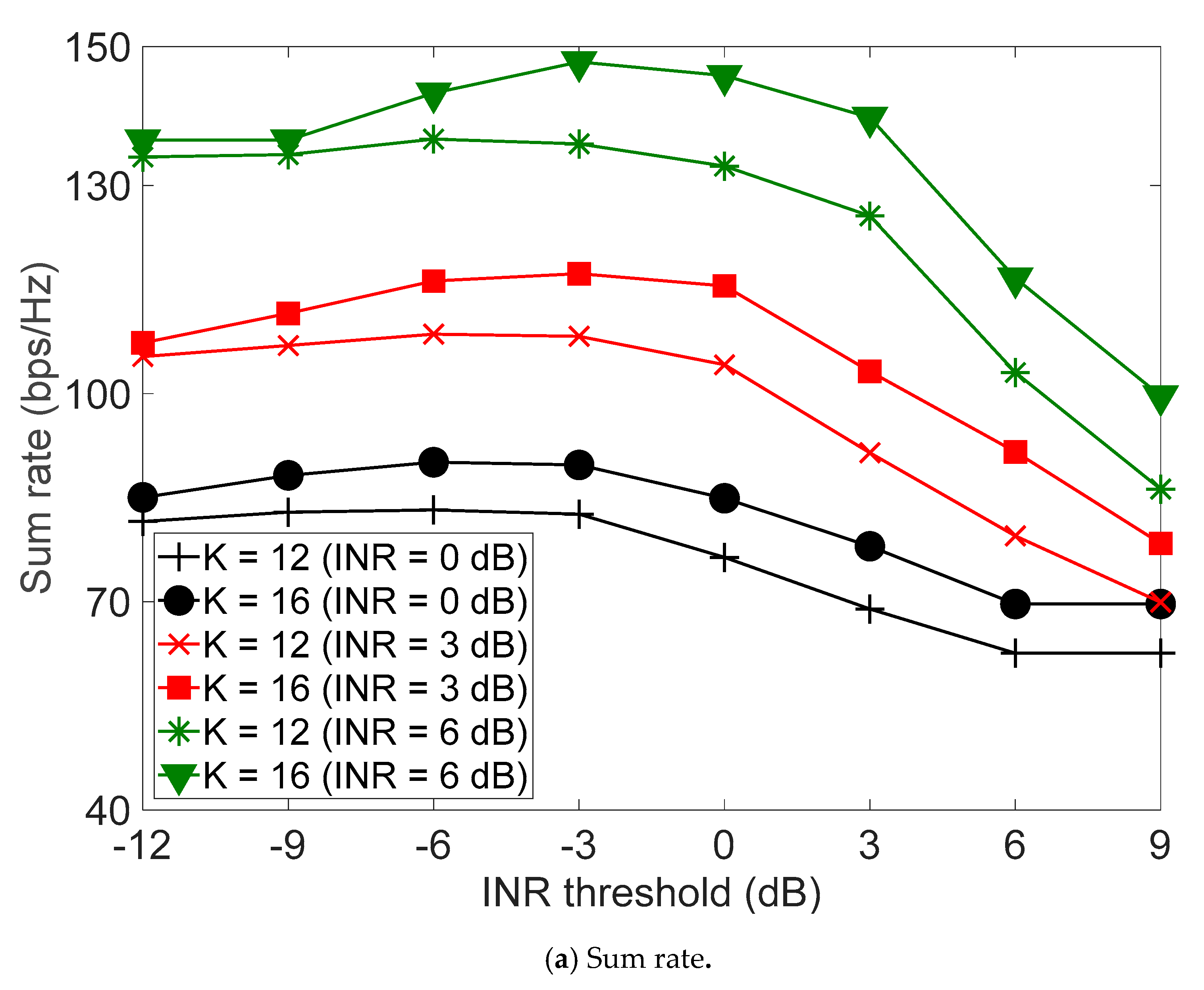
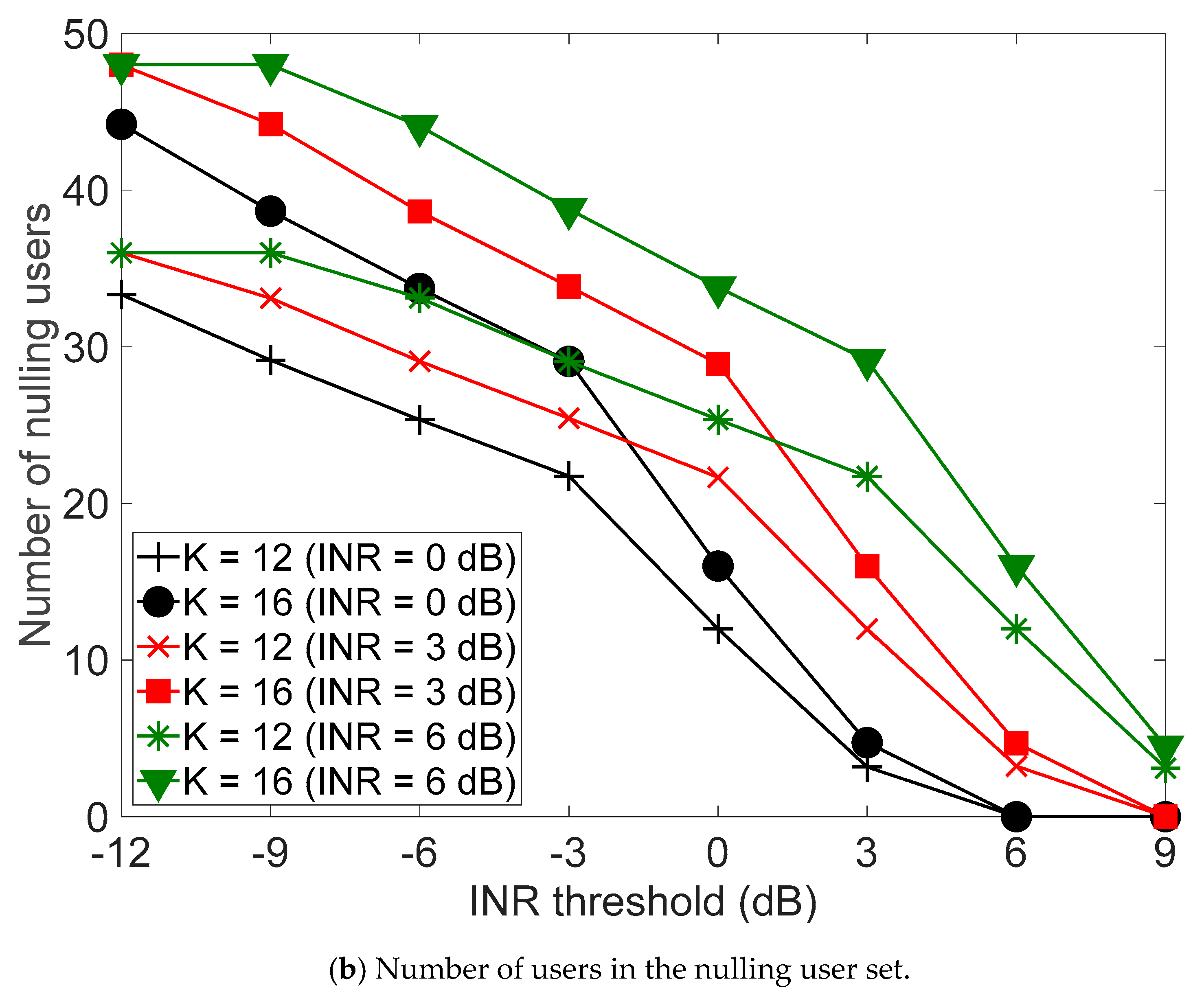
Figure 3 depicts the sum rate and the number of users in the nulling user set of the MUPB according to the threshold δ th when M = 64 , K = 12 ,   16 , and the INR is 0 dB, 3 dB, 6 dB. It can be seen that as K increases, δ th maximizing the sum rate and the number of users in the nulling user set increase as well. That is, when K is large, the number of users in the nulling user set needs to be decreased to avoid performance degradation by the PZF. Otherwise, the MUPB may suffer from performance degradation mainly due to the absence of sufficient spatial DoF for the PZF. It can also be seen that when δ th is large, the performance severely degrades even for large K due to the presence of large interference caused by a small number of users in the nulling user set. This implies that the number of users in the nulling user set should properly be adjusted for the generation of MUPB beam weight. It can also be seen that the number of users in the nulling user set should be large to reduce interference in multi-user environments.
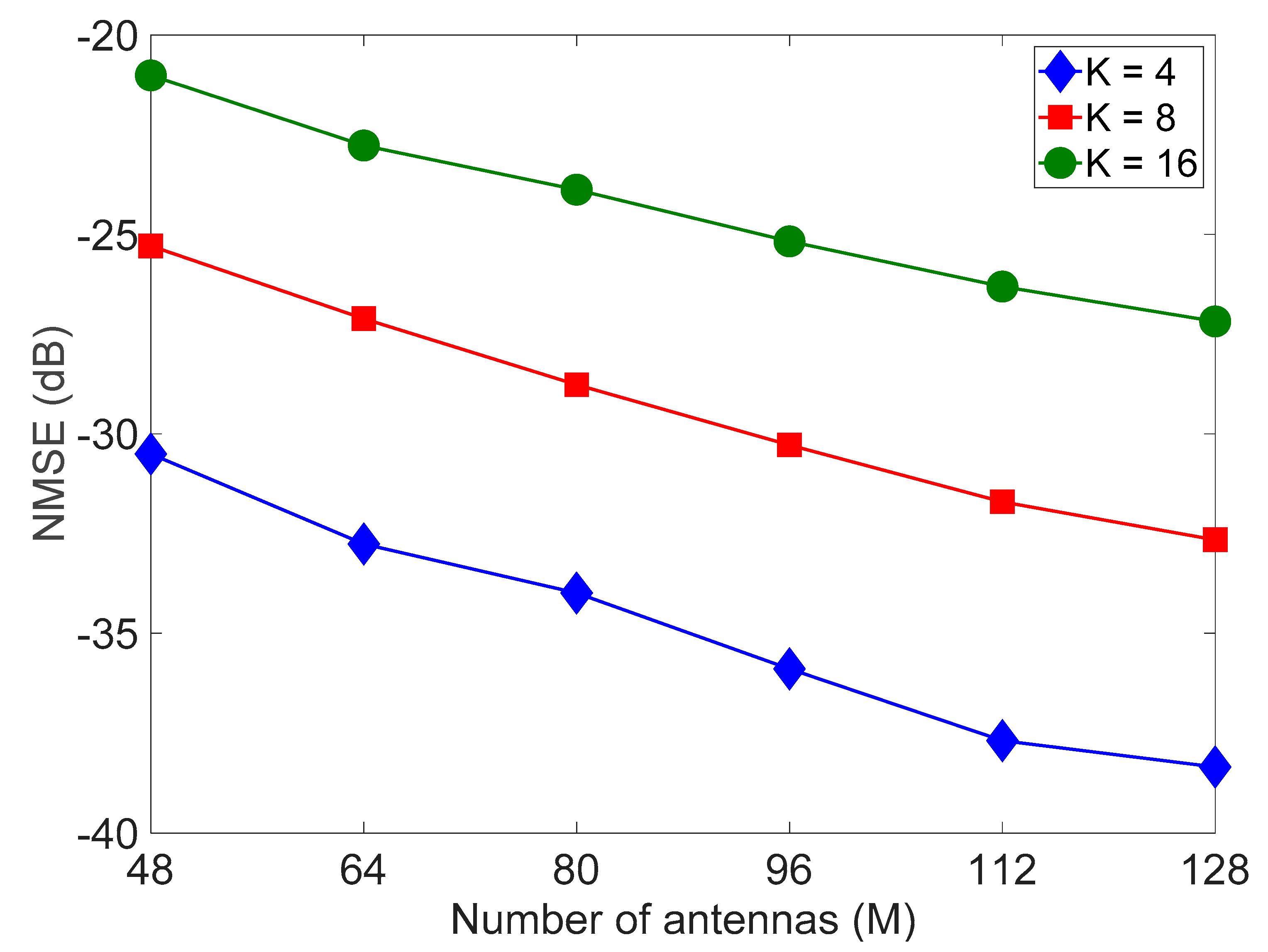
Figure 4 depicts the normalized mean square error (NMSE) of SLNR approximation in the MUPB according to the number of antennas M when K = 4 ,   8 ,   16 . We define the NMSE by
NMSE = 1 K total k = 1 K total ( SLNR k * SLNR k MUPB ) 2 ( SLNR k * ) 2
where SLNR k * is the optimum SLNR of user k obtained by Rayleigh–Ritz quotient theorem, SLNR k MUPB is the approximated SLNR of user k in the MUPB, and the threshold δ th is determined to minimize the NMSE. It can be seen that the validity of the proposed approximation increases as M increases. This is mainly because the deterministic equivalent property, applied to the approximation of SLNR, becomes accurate as M increases. As a consequence, the proposed MUPB can provide performance slightly worse than the Max SLNR, while significantly reducing the computational complexity.
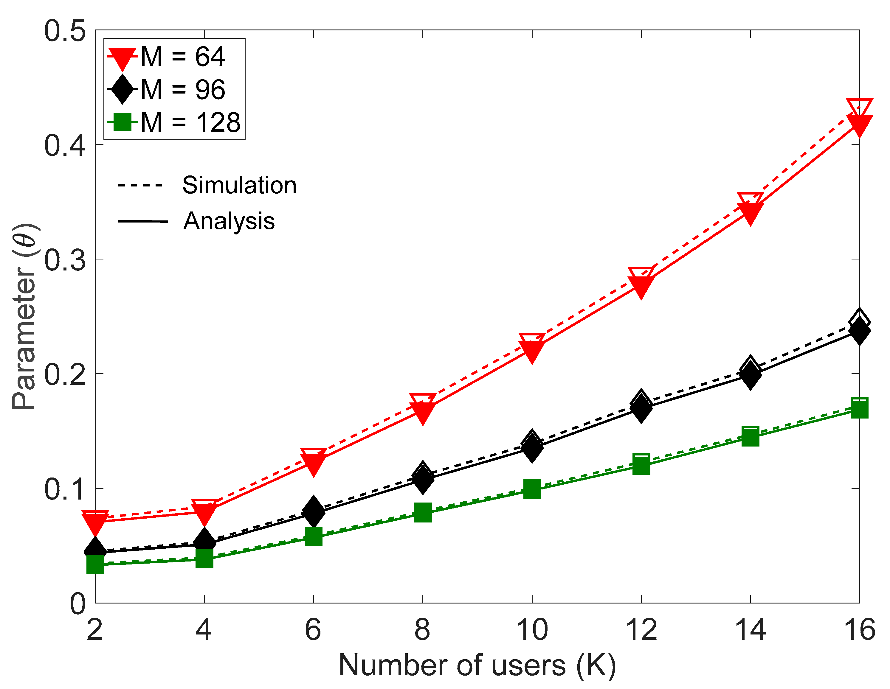
Figure 5 depicts the parameter θ according to K when M = 64 ,   96 ,   128 and δ th = 6   dB . It can be seen that as K increases, θ also increases. When K is large, the PZF may experience performance deterioration mainly due to the absence of sufficient spatial DoF. In this case, θ needs to be increased so as to maximize the approximated SLNR. It can be seen that as M increases, θ decreases. When M is large, the approximated SLNR can be maximized by reducing the leakage power with the use of small θ .
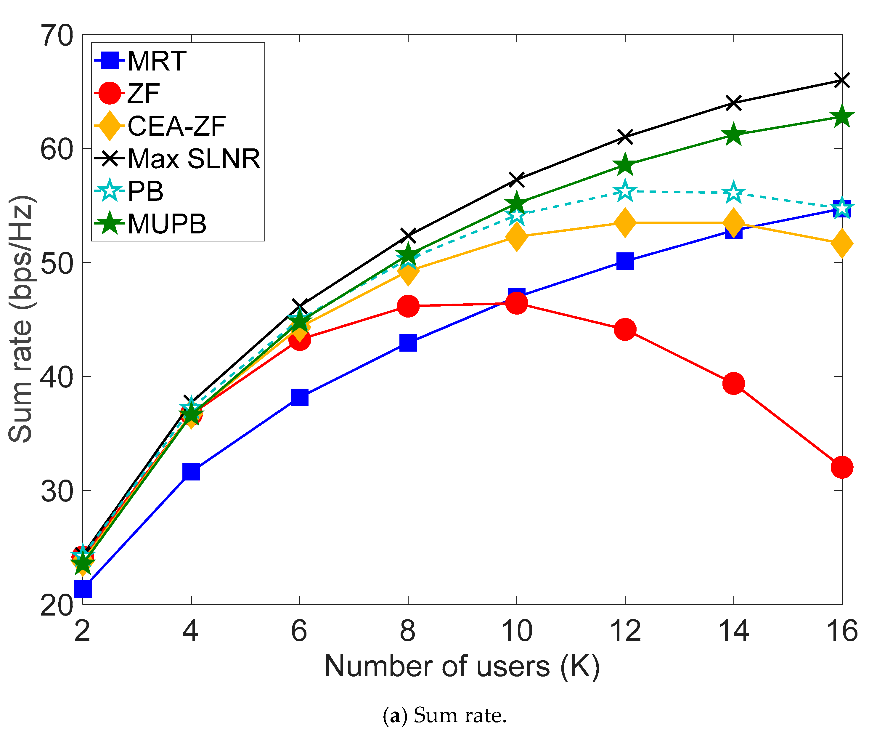
Figure 6 depicts the performance of the proposed MUPB in terms of the sum rate and the computational complexity according to K when M = 64 and δ th = 6   dB . For comparison, we also evaluate the performance of MRT [4], ZF [6], CEA-ZF [19], Max SNLR [23], and PB that maximizes the approximated SLNR by (51) with combined use of MRT and ZF. It can be seen that the MUPB provides performance slightly worse than the Max SLNR, while outperforming the other schemes. It can also be seen that the MRT and the ZF may be effective in certain operation environments, and the CEA-ZF can work better than the ZF since it does not require full dimensional nulling subspace. However, since the CEA-ZF determines the beam weight without consideration of SINR or SLNR, it may provide marginal performance improvement. The PB and the MUPB work better than the CEA-ZF since their beam weight is determined to maximize the approximated SLNR. However, as K increases, the performance gap between the PB and the MUPB increases since the PB may suffer from the absence of sufficient spatial DoF due to the use of ZF. It can be seen that the MUPB requires the computational complexity much lower than the Max SLNR, the ZF, and the PB. The MUPB can outperform the CEA-ZF, while requiring the computational complexity similar to the CEA-ZF.
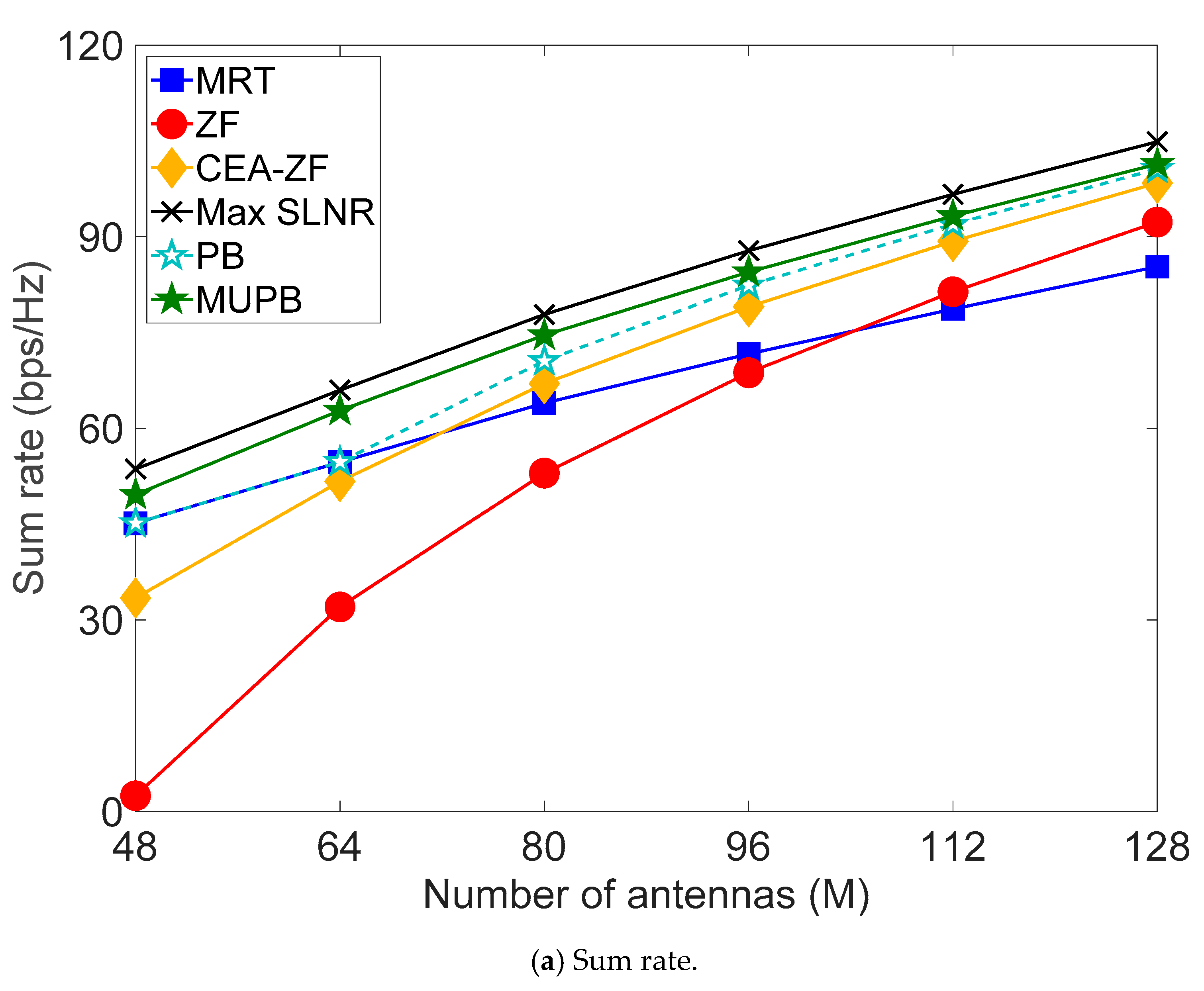
Figure 7 compares the sum rate and the computational complexity according to M when K = 16 and δ th = 6   dB . It can be seen that the MUPB provides performance improvement over the other schemes other than the Max SLNR which requires unaffordable computational complexity.

5. Conclusions

In this paper, we have proposed a low-complexity multi-user beamforming scheme MUPB in m-MIMO environments. To reduce the computational complexity, we have determined the beam weight of MUPB to maximize approximated SLNR with combined use of MRT and partial ZF. The simulation results show that the MUPB provides performance slightly worse than the Max SLNR, while significantly reducing the computational complexity.

Author Contributions

G.-W.J. conceived the main idea of this paper and designed the proposed scheme. The mathematical analysis and the experiments were performed by G.-W.J.; Y.-H.L. directed the academic research. G.-W.J. wrote the paper and Y.-H.L. revised the manuscript. All authors have read and agreed to the published version of the manuscript.

Funding

This work was supported by the National Research Foundation of Korea(NRF) grant funded by the Korea government(MSIT) (No. 2019R1F1A1063171).

Acknowledgments

The authors would like to thank the Editor and the anonymous reviewers for their valuable comments and suggestions.

Conflicts of Interest

The authors declare no conflict of interest.

Appendix A

Proof of Lemma 4.
Let user k be the u-th user in U i o . G k PZF can be represented as [6]
G k PZF = G k MRT D k PZF
where
D k PZF = n u K i o D u , n PZF
here, D u , n PZF can be represented as
D u , n PZF = ( 1 ) u + n + 1 h k H h n i o Θ u , n
where
Θ u , n = det ( R u , n ) det ( R u , u )
here, R = ( H i o ) H H i o and R u , n denotes R without the u-th row and the n-th column. It can be shown that [34]
Θ u , n = p = 1 K i , k o ( 1 ) p + l u , n h b i o H h k det ( [ R u , n ] p , l u , n ) p = 1 K i , k o ( 1 ) p + l n , u h b i o H h n i o det ( [ R u , u ] p , l n , u ) = ( 1 ) z u , n p = 1 K i , k o w u , n ( p ) h b i o H h k p = 1 K o w u , n ( p ) h b i o H h n i o
where
l u , n = { u   for   u < n u 1   for   u > n
z u , n = { u n + 1   for   u < n u n 1   for   u > n
b = { p   for   p < u p + 1   for   p > u
w u , n ( p ) = ( 1 ) p det ( [ R u , u ] p , l n , u )
Since ( 1 ) u + n + 1 ( 1 ) z u , n = 1 irrespective of u and n, it can also be shown that
D u , n PZF = p = 1 K i , k o f u , n ( p ) p = 1 K i , k o g u , n ( p ) = f u , n ( l n , u ) + p l n , u K i , k o f u , n ( p ) g u , n ( l n , u ) + p l n , u K i , k o g u , n ( p )
where f u , n ( p ) = w u , n ( p ) h b i o H h k h k H h n i o and g u , n ( p ) = w u , n ( p ) h b i o H h n i o . It can be seen from Lemma 2 that for b n h b i o H h k h k H h n i o M a . s . 0 and h b i o H h n i o M a . s . 0 , and that p l n , u K i , k o f u , n ( p ) M a . s . 0 and p l n , u K i , k o g u , n ( p ) M a . s . 0 . It can be shown that
f u , n ( l n , u ) g u , n ( l n , u ) = h k H h n i o h n i o H h k h n i o H h n i o .
It can be seen from Lemma 1 that h k H h n i o h n i o H h k tr ( h n i o h n i o H ) M a . s . 0 , and thus f u , n i o ( l n , u ) / g u , n i o ( l n , u ) 1 M a . s . 0 . It can be shown that D k PZF K i , k o M a . s . 0 . Finally, it can be shown that G k PZF G ¯ k PZF M a . s . 0 , where G ¯ k PZF = M K i , k o .

Appendix B

Proof of Lemma 5.
It can be shown from Lemma 1 that
h i , k H P i , k o h i , k tr ( P i , k o ) M a . s . 0 .
It can be seen from Lemma 3 and 4 that
q k q ¯ k M a . s . 0
where q ¯ k is a deterministic equivalent of q k and can be represented as
q ¯ k = tr ( P i , k o ) M M K i , k o .
Since tr ( P i , k o ) = M K i , k o , it can be seen that
q ¯ k = M K i , k o M 1 K i , k o M .
Thus, it can be seen that lim M q ¯ k 1 .

Appendix C

Proof of strict quasi-concavity of  SLNR ¯ k .
We prove that SLNR ¯ k is a strict quasi-concave function of θ k by using the following Theorem A1 [28].
Theorem A1.
A continuous function f : R R is strictly quasi-concave if and only if there is a point c dom   f such that f is an increasing function for x < c ( x dom   f ), and f is a decreasing function for x > c ( x dom   f ). The point c can be chosen by any point that globally maximizes f.
Let c k be a global maximizer of SLNR ¯ k . Without loss of generality, we can assume that c k can be set to σ n 2 L ¯ U k o MRT Δ G ¯ k G ¯ k PZF since the global optimum occurs at which the gradient vanishes [28]. For θ k < c k , θ k can be set to θ k * ε , where ε is an arbitrary positive real number satisfying θ k * ε [ 0 , 1 ] . For θ k < c k , Φ k in (49) and Γ k in (50) can be represented as, respectively,
Φ k = 2 p k α i , k ( L ¯ U i , k o MRT θ k 2 + σ n 2 ) 2 [ G ¯ k PZF ( σ n 2 Δ G ¯ k L ¯ U i , k o MRT G ¯ k PZF + 1 ) Δ G ¯ k ε ]
Γ k = L ¯ U i , k o MRT G ¯ k PZF θ k ε
It can be shown that
θ k SLNR ¯ k = ε N k D k
where
N k = 2 p k α i , k L ¯ U i , k o MRT G ¯ k PZF ( Δ G ¯ k θ k + G ¯ k PZF )
D k = ( L ¯ U i , k o MRT θ k 2 + σ n 2 ) 2
It can be seen that N k > 0 since θ k 0 and D k > 0 . Then, it can be shown for θ k < c k that SLNR ¯ k is a strictly increasing function since θ k SLNR ¯ k > 0
For θ k > c k , θ k can be set to θ k * + ε , where ε is an arbitrary positive real number satisfying θ k * + ε [ 0 , 1 ] . It can be shown for θ k > c k that
θ k SLNR ¯ k = ε N k D k
It can be seen for θ k > c k that SLNR ¯ k is a strictly decreasing function since θ k SLNR ¯ k < 0 . Finally, it can be shown from Theorem A1 that SLNR ¯ k is a strict quasi-concave function of θ k .

References

  1. Yang, P.; Xiao, Y.; Xiao, M.; Li, S. 6G wireless communications: Vision and potential techniques. IEEE Netw. 2019, 33, 70–75. [Google Scholar] [CrossRef]
  2. Maruta, K.; Falcone, F. Massive MIMO systems: Present and future. Electronics 2020, 9, 385. [Google Scholar] [CrossRef] [Green Version]
  3. Viswanathan, H.; Mogensen, P.E. Communications in the 6G era. IEEE Access 2020, 8, 57063–57074. [Google Scholar] [CrossRef]
  4. Marzetta, T.L. Noncooperative cellular wireless with unlimited numbers of base station antennas. IEEE Trans. Wirel. Commun. 2010, 9, 3590–3600. [Google Scholar] [CrossRef]
  5. Rusek, F.; Persson, D.; Lau, B.K.; Larsson, E.G.; Marzetta, T.L.; Edfors, O.; Tufvesson, F. Scaling up MIMO: Opportunities and challenges with very large arrays. IEEE Trans. Signal Process. Mag. 2013, 30, 40–60. [Google Scholar] [CrossRef] [Green Version]
  6. Wong, K.; Pan, Z. Array gain and diversity order of multiuser MISO antenna systems. Int. J. Wirel. Inf. Netw. 2008, 15, 82–89. [Google Scholar] [CrossRef]
  7. Moon, S.H.; Lee, C.; Lee, S.R.; Lee, I. Joint user scheduling and adaptive intercell interference cancelation for MISO downlink cellular systems. IEEE Trans. Veh. Technol. 2013, 62, 172–181. [Google Scholar] [CrossRef]
  8. Lu, L.; Li, G.Y.; Swindlehurst, A.L.; Ashikhmin, A.; Zhang, R. An overview of massive MIMO: Benefits and challenges. IEEE J. Sel. Top. Signal Process. 2014, 8, 742–758. [Google Scholar] [CrossRef]
  9. Prabhu, H.; Rodrigues, J.; Edfors, O.; Rusek, F. Approximative matrix inverse computations for very-large MIMO and applications to linear pre-coding systems. In Proceedings of the IEEE Wireless Communications and Networking Conference (WCNC), Shanghai, China, 7–10 April 2013; pp. 2710–2715. [Google Scholar]
  10. Kammoun, A.; Müller, A.; Björnson, E.; Debbah, M. Linear precoding based on polynomial expansion: Large-scale multi-cell MIMO systems. IEEE J. Sel. Top. Signal Process. 2014, 8, 861–875. [Google Scholar] [CrossRef] [Green Version]
  11. Man, Y.; Li, Z.; Yan, F.; Xing, S.; Shen, L. Massive MIMO pre-coding algorithm based on truncated Kapteyn series expansion. In Proceedings of the IEEE International Conference on Communication Systems (ICCS), Shenzhen, China, 14–16 December 2016; pp. 1–5. [Google Scholar]
  12. Lee, K.; Chen, C. An eigen-based approach for enhancing matrix inversion approximation in massive MIMO systems. IEEE Trans. Veh. Techol. 2017, 66, 5483–5487. [Google Scholar]
  13. Gao, X.; Dai, L.; Zhang, J.; Han, S.; I, C.L. Capacity-approaching linear precoding with low-complexity for large-scale MIMO systems. In Proceedings of the IEEE International Conference on Communications (ICC), London, UK, 8–12 June 2015; pp. 1577–1582. [Google Scholar]
  14. Xie, T.; Dai, L.; Gao, X.; Dai, X.; Zhao, Y. Low-complexity SSOR-based precoding for massive MIMO systems. IEEE Commun. Lett. 2016, 20, 744–747. [Google Scholar] [CrossRef]
  15. Man, Y.; Zhang, C.; Li, Z.; Yan, F.; Xing, S.; Shen, L. Massive MIMO precoding algorithm based on improved Newton iteration. In Proceedings of the IEEE 85th Vehicular Technology Conference (VTC Spring), Sydney, Australia, 4–7 June 2017; pp. 1–5. [Google Scholar]
  16. Minango, J.; Almeida, C. A low-complexity linear precoding algorithm based on Jacobi method for massive MIMO systems. In Proceedings of the IEEE 87th Vehicular Technology Conference (VTC Spring), Porto, Portugal, 3–6 June 2018; pp. 1–5. [Google Scholar]
  17. Liu, Y.; Liu, J.; Wu, Q.; Zhang, Y.; Jin, M. A near-optimal iterative linear precoding with low complexity for massive MIMO systems. IEEE Commun. Lett. 2019, 23, 1105–1108. [Google Scholar] [CrossRef]
  18. Lee, C.; Moon, S.H.; Lee, S.R.; Lee, I. Adaptive beamforming selection methods for inter-cell interference cancellation in multicell multiuser systems. In Proceedings of the IEEE International Conference on Communications (ICC), Budapest, Hungary, 9–13 June 2013; pp. 5684–5688. [Google Scholar]
  19. Yang, H.H.; Geraci, G.; Quek, T.Q.S.; Andrews, J.G. Cell-edge-aware precoding for downlink massive MIMO cellular networks. IEEE Trans. Signal Process. 2017, 65, 3344–3358. [Google Scholar] [CrossRef]
  20. Venturino, L.; Prasad, N.; Wang, X. Coordinated linear beamforming in downlink multicell wireless networks. IEEE Trans. Wirel. Commun. 2010, 9, 1451–1461. [Google Scholar] [CrossRef]
  21. Garzás, J.J.E.; Hong, M.; Garcia, A.; García-Armada, A. Interference pricing mechanism for downlink multicell coordinated beamforming. IEEE Trans. Commun. 2014, 62, 1871–1883. [Google Scholar] [CrossRef] [Green Version]
  22. Sadek, M.; Tarighat, A.; Sayed, A.H. A leakage-based precoding scheme for downlink multi-user MIMO channels. IEEE Trans. Wirel. Commun. 2007, 6, 1711–1721. [Google Scholar] [CrossRef]
  23. Boukhedimi, I.; Kammoun, A.; Alouini, M. Coordinated SLNR based precoding in large-scale heterogeneous networks. IEEE J. Sel. Top. Signal Process. 2017, 11, 534–548. [Google Scholar] [CrossRef] [Green Version]
  24. Jorswieck, E.; Larsson, E.; Danev, D. Complete characterization of the Pareto boundary for the MISO interference channel. IEEE Trans. Signal Process. 2008, 56, 5292–5296. [Google Scholar] [CrossRef] [Green Version]
  25. Mochaourab, R.; Jorswieck, E. Optimal beamforming in interference networks with perfect local channel information. IEEE Trans. Signal Process. 2011, 59, 1128–1141. [Google Scholar] [CrossRef]
  26. Couillet, R.; Debbah, M. Random Matrix Methods for Wireless Communications, 1st ed.; Cambridge University Press: Cambridge, UK, 2011. [Google Scholar]
  27. Ngo, H.; Larsson, E.; Marzetta, T.L. Energy and spectral efficiency of very large multiuser MIMO systems. IEEE Trans. Commun. 2013, 61, 1436–1449. [Google Scholar]
  28. Boyd, S.; Vandenberghe, L. Convex Optimization; Cambridge University Press: Cambridge, UK, 2004. [Google Scholar]
  29. Hunger, R. Floating Point Operations in Matrix-Vector Calculus; Technical Report; Munich University of Technology: Munich, Germany, 2007. [Google Scholar]
  30. He, S.; Huang, Y.; Yang, L.; Ottersten, B. Coordinated multicell multiuser precoding for maximizing weighted sum energy efficiency. IEEE Trans. Signal Process. 2014, 62, 741–751. [Google Scholar] [CrossRef]
  31. Horn, R.; Johnson, C. Matrix Analysis; Cambridge University Press: Cambridge, UK, 1985. [Google Scholar]
  32. Parkvall, S.; Dahlman, E.; Furuskär, A.; Jading, Y.; Olsson, M.; Wänstedt, S.; Zangi, K. LTE-Advanced—Evolving LTE towards IMT-Advanced. In Proceedings of the IEEE 68th Vehicular Technology Conference, Calgary, AB, Canada, 21–24 September 2008; pp. 1–5. [Google Scholar]
  33. Pan, C.; Ren, H.; Elkashlan, M.; Nallanathan, A.; Hanzo, L. The non-coherent ultra-dense C-RAN is capable of outperforming its coherent counterpart at a limited fronthaul capacity. IEEE J. Sel. Areas Commun. 2018, 36, 2549–2560. [Google Scholar] [CrossRef] [Green Version]
  34. Rose, H.E. Linear Algebra: A Pure Mathematical Approach; Birkhaüser: Basel, Switzerland, 2002. [Google Scholar]
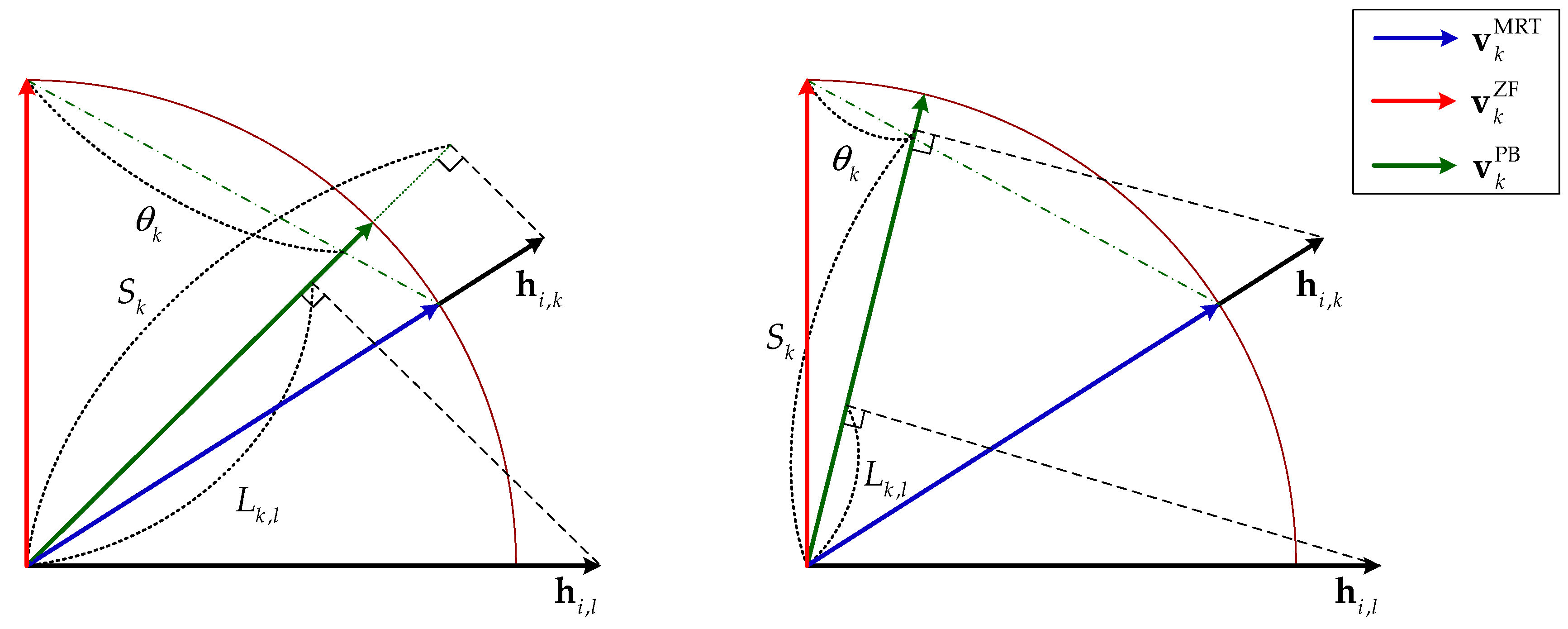
Figure 1. Behavior of parameterized beamforming (PB) according to parameter θ k .
Electronics 09 00882 g001
Figure 2. A three-cell cellular system.
Electronics 09 00882 g002
Figure 3. Performance of multi-user parameterized beamforming (MUPB) according to δ th .
Electronics 09 00882 g003aElectronics 09 00882 g003b
Figure 4. Normalized mean square error (NMSE) performance of MUPB according to M.
Electronics 09 00882 g004
Figure 5. Parameter θ according to K when δ th = 6   dB .
Electronics 09 00882 g005
Figure 6. Performance according to K when M = 64 and δ th = 6   dB .
Electronics 09 00882 g006aElectronics 09 00882 g006b
Figure 7. Performance according to M when K = 16 and δ th = 6   dB .
Electronics 09 00882 g007aElectronics 09 00882 g007b
Table 1. Computational complexity for the generation of beam weight.
SchemeComputational Complexity
MRT 4 K total M
ZF B K total M 2 + ( 8 B K total + 4 ) K total M + 4 3 B K total 3
CEA-ZF i = 1 B [ ( K i + K i E ) M 2 + ( 8 ( K i + K i E ) 2 + 4 K i ) M + 4 3 ( K i + K i E ) 3 ]
Max SLNR 4 3 K total M 3 + ( ( B + 8 ) K total + 2 ( B 1 ) ) M 2 + 6 K total M
PB B K total M 2 + ( 8 B K total + 18 ) K total M + 4 3 B K total 3
MUPB i = 1 B ( ψ i MRT + ψ i PZF ) + [ B ( B 1 ) + 10 M ] K total
Table 2. Simulation parameters.
Simulation ParametersValue
Number of BSs B3
Cell radius R max 300 m
Cell center radius R c 200 m
Path loss α i , k ,   i   and   k 148.1 + 37.6 log 10 ( d i , k )   dB , where d i , k is
the distance between BS i and user k in km
Maximum transmit power P T 30 dBm
Power allocation p k ,   k P T / K
Noise power σ n 2 −92 dBm