An Overview of FIR Filter Design in Future Multicarrier Communication Systems


Abstract
1. Introduction
2. Multicarrier Modulations and FIR Filter
2.1. Modulation Waveforms
2.1.1. OFDM
2.1.2. FBMC
2.1.3. GFDM
2.1.4. UFMC
2.1.5. F-OFDM
2.2. FIR Filter
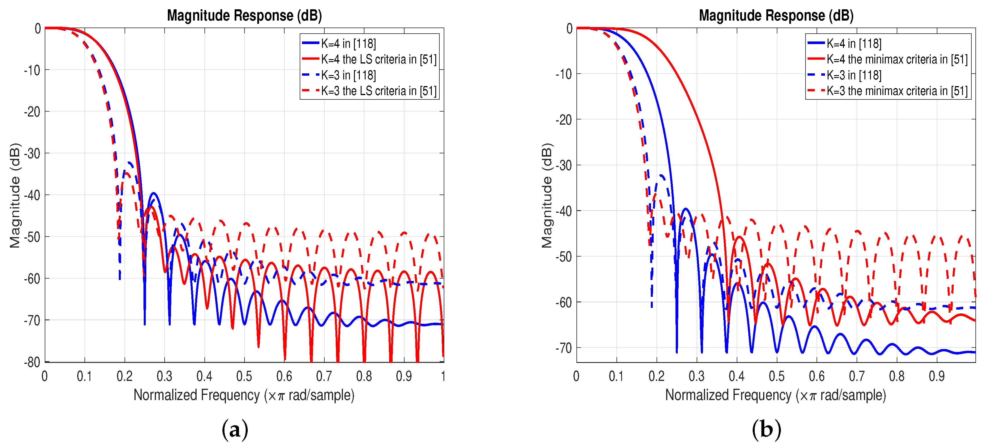
- LS criterionThe goal of the least-squares criterion is to minimize the stopband energy of the filter, whose objective function is
- Minimax criterionThe goal of the minimax criterion is to minimize the maximum stopband ripple, and its objective function can be written as
- PCLS criterionThe PCLS criterion establishes a trade-off between the LS and the minimax criteria. The PCLS criterion can be described as belowwhere is a prescribed value. If is close to zero, the PCLS criterion approaches the minimax criterion, while in the limit of , that is, is up to infinite, the criterion turns out the LS criterion.
- Minimum total interference criterionThis criterion is to minimize the total interference of ICI and ISI for filter bank structure. Its objective function is defined aswherewhere is the transfer matrix, the element represents the relationship between the input signal and the output signal , where z is the complex argument of z-transform. is the ideal impulse, and △ denotes the delay of the TMUX system. Thus the transfer function between input and output signals is given bywhere
3. FIR Prototype Filter Design
3.1. Frequency Sampling Methods
3.1.1. Bellanger’s Method
3.1.2. Viholainen’s Method
3.1.3. Cruz-Roldán’s Method I
- (a)
- Initialize the filter length N and the required number of samples L in the transition band.
- (b)
- Initialize the frequency response in (27) and (28). The resulting vector is presented as followswhere .
- (c)
- Let be the vector whose elements are the samples of the magnitude response at the transition band. Find and minimize an objective function defined as [122]where M is related to the number of channels, is the DFT of and defined as .
- (d)
- (e)
3.1.4. Cruz-Roldán’s Method II
3.1.5. Salcedo-Sanz’s Method
3.2. Windowing Based Methods
- step 1:
- Taking linear phase low-pass FIR filter as an example, the general selection of iswhere is a constant.
- step 2:
- Determine via IDFT
- step 3:
- The impulse response of the linear phase FIR filter is obtained by multiplying a specific window , as belowThus the corresponding is obtained by DFT.
3.2.1. Jain’s Method
3.2.2. Kumar’s Method
3.2.3. Mottaghi-Kashtiban’s Method
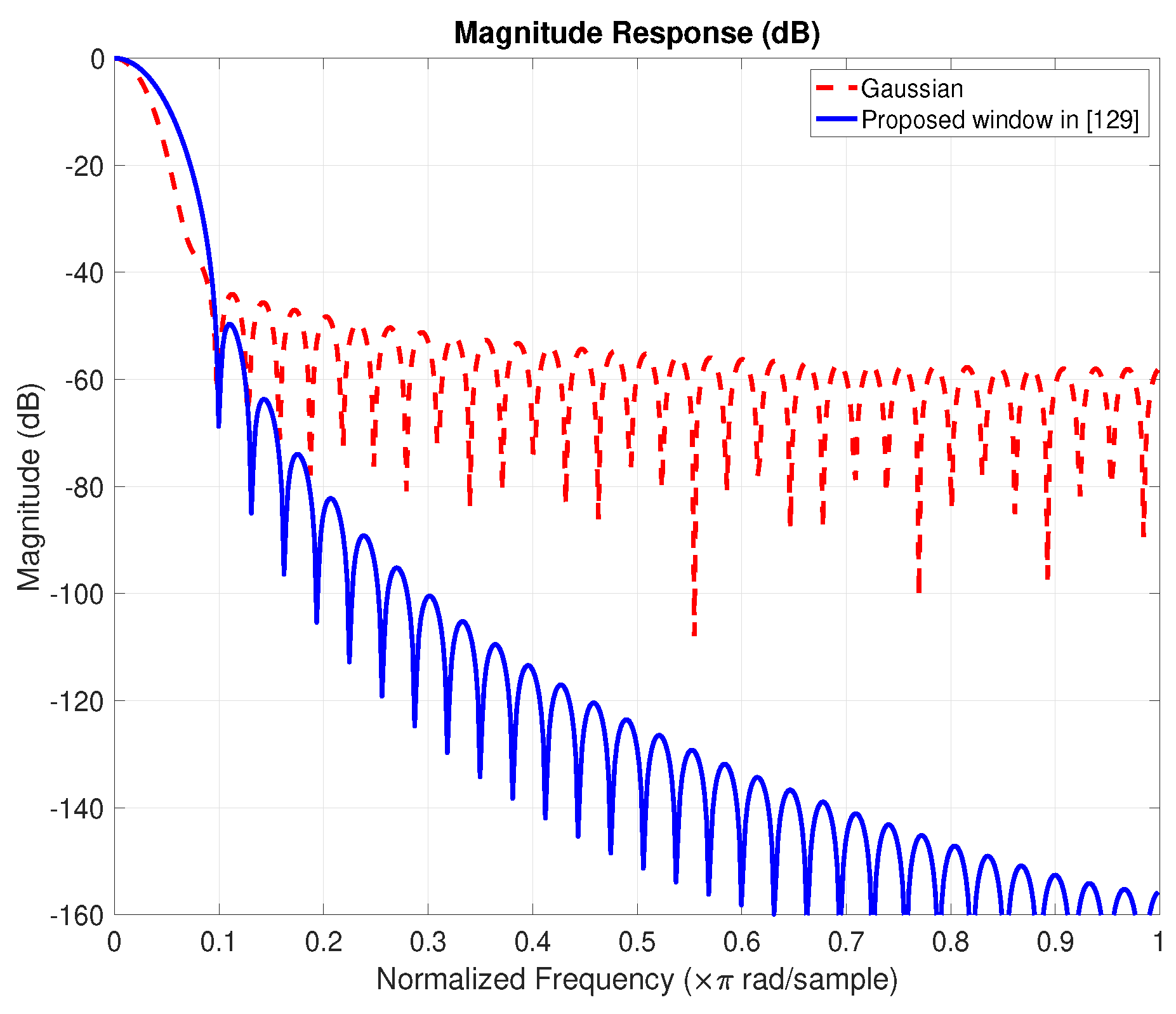
3.2.4. Rakshit’s Method
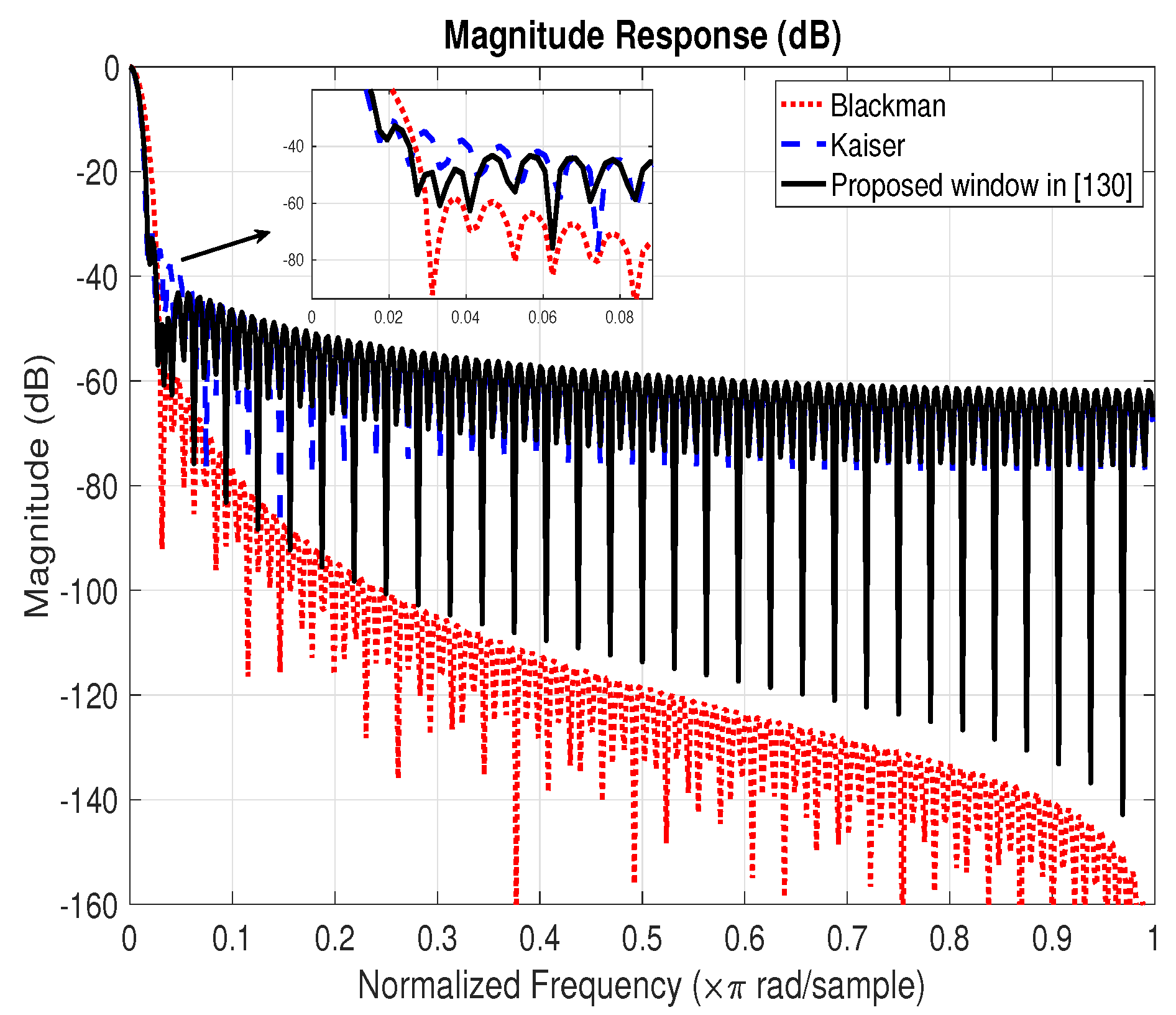
3.2.5. Martin-Martin’s Method
3.3. Optimization Based Methods
3.3.1. Ababneh’s Method
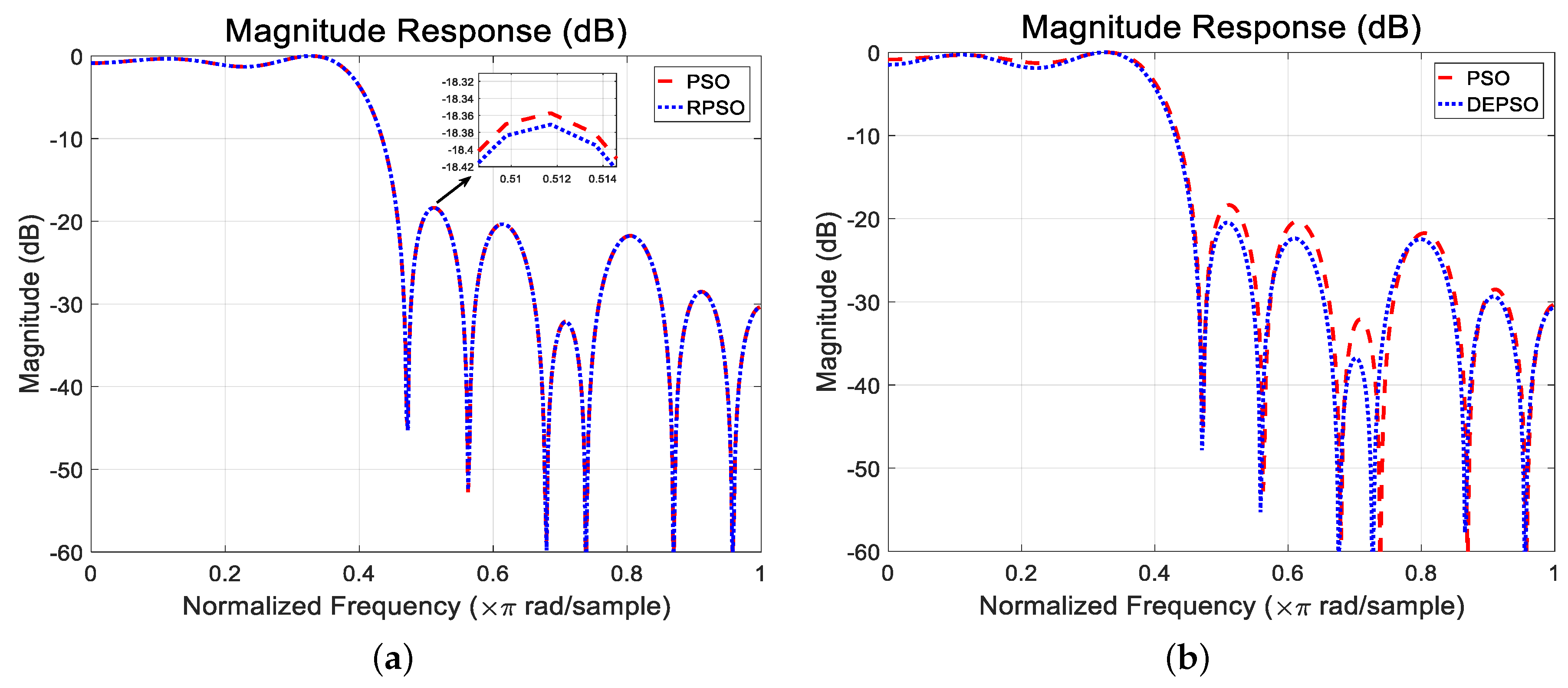
3.3.2. Luitel’s Method
3.3.3. Gupta’s Method
3.3.4. Li’s Method
| Algorithm 1 The GA Algorithm. |
| Input: Initialize parameters: population size , current generation , maximum generation , swarm S; Output: The best resolution ;
|
3.3.5. Karaboga’s Method
| Algorithm 2 The DE Algorithm. |
| Input: Initialize parameters: population size , current generation , maximum generation , dimension D, tolerance , swarm S, base vector s, mutant vector v, trial vector u; Output: The best resolution ; for do for do ; end for end for while do for i = 1 to NP do for d = 1 to D do ; ; end for if then ; if then ; end if else ; end if end for ; end while return The best resolution . |
3.3.6. Chen’s Method
3.3.7. Hunziker’s Method
3.3.8. Dedeoğlu’s Method
3.3.9. Kobayashi’s Method
4. Discussion
4.1. Frequency Sampling Methods
4.2. Windowing Based Methods
4.3. Optimization Based Methods
5. Conclusions
Author Contributions
Funding
Conflicts of Interest
References
- Andrews, J.G.; Buzzi, S.; Choi, W.; Hanly, S.V.; Lozano, A.; Soong, A.C.K.; Zhang, J.C. What Will 5G Be? IEEE J. Sel. Areas Commun. 2014, 32, 1065–1082. [Google Scholar] [CrossRef]
- Agiwal, M.; Roy, A.; Saxena, N. Next Generation 5G Wireless Networks: A Comprehensive Survey. IEEE Commun. Surv. Tutor. 2016, 18, 1617–1655. [Google Scholar] [CrossRef]
- Gupta, A.; Jha, R.K. A Survey of 5G Network: Architecture and Emerging Technologies. IEEE Access 2015, 3, 1206–1232. [Google Scholar] [CrossRef]
- Sahin, A.; Guvenc, I.; Arslan, H. A Survey on Multicarrier Communications: Prototype Filters, Lattice Structures, and Implementation Aspects. IEEE Commun. Surv. Tutor. 2014, 16, 1312–1338. [Google Scholar] [CrossRef]
- Kaiwartya, O.; Abdullah, A.H.; Cao, Y.; Altameem, A.; Prasad, M.; Lin, C.T.; Liu, X. Internet of Vehicles: Motivation, Layered Architecture, Network Model, Challenges, and Future Aspects. IEEE Access 2016, 4, 5356–5373. [Google Scholar] [CrossRef]
- Chen, K.W.; Wang, C.H.; Wei, X.; Liang, Q.; Chen, C.S.; Yang, M.H.; Hung, Y.P. Vision-Based Positioning for Internet-of-Vehicles. IEEE Trans. Intell. Transp. Syst. 2017, 18, 364–376. [Google Scholar] [CrossRef]
- Zhang, W.; Xi, X. The innovation and development of Internet of Vehicles. China Commun. 2016, 13, 122–127. [Google Scholar] [CrossRef]
- Pishva, D. Internet of Things: Security and privacy issues and possible solution. In Proceedings of the International Conference Infocomm Commun. Technoligy (ICACT), Bongpyeong, Korea, 19–22 Feburary 2017; pp. 797–808. [Google Scholar]
- Yaqoob, I.; Ahmed, E.; Hashem, I.A.T.; Ahmed, A.I.A.; Gani, A.; Imran, M.; Guizani, M. Internet of Things Architecture: Recent Advances, Taxonomy, Requirements, and Open Challenges. IEEE Wirel. Commun. 2017, 24, 10–16. [Google Scholar] [CrossRef]
- Morin, E.; Maman, M.; Guizzetti, R.; Duda, A. Comparison of the Device Lifetime in Wireless Networks for the Internet of Things. IEEE Access 2017, 5, 7097–7114. [Google Scholar] [CrossRef]
- Rosedale, P. Virtual Reality: The Next Disruptor: A new kind of worldwide communication. IEEE Consum. Electron. Mag. 2017, 6, 48–50. [Google Scholar] [CrossRef]
- Serafin, S.; Erkut, C.; Kojs, J.; Nilsson, N.C.; Nordahl, R. Virtual Reality Musical Instruments: State of the Art, Design Principles, and Future Directions. Comput. Music J. 2016, 40, 22–40. [Google Scholar] [CrossRef]
- Douik, A.; Sorour, S.; Tembine, H.; Al-Naffouri, T.Y.; Alouini, M.S. A Game-Theoretic Framework for Network Coding Based Device-to-Device Communications. IEEE Trans. Mob. Comput. 2017, 16, 901–917. [Google Scholar] [CrossRef]
- Chen, B.; Yang, C.; Molisch, A.F. Cache-Enabled Device-to-Device Communications: Offloading Gain and Energy Cost. IEEE Trans. Wirel. Commun. 2017, 16, 4519–4536. [Google Scholar] [CrossRef]
- Haus, M.; Waqas, M.; Ding, A.Y.; Li, Y.; Tarkoma, S.; Ott, J. Security and Privacy in Device-to-Device (D2D) Communication: A Review. IEEE Commun. Surv. Tutor. 2017, 19, 1054–1079. [Google Scholar] [CrossRef]
- Liu, J.; Kato, N.; Ma, J.; Kadowaki, N. Device-to-Device Communication in LTE-Advanced Networks: A Survey. IEEE Commun. Surv. Tutor. 2015, 17, 1923–1940. [Google Scholar] [CrossRef]
- Miao, L.; Na, L.; Sun, Z. Optimal deactivated sub-carriers guard bands for spectrum pooling systems based on wavelet-based orthogonal frequency division multiplexing. IET Commun. 2014, 8, 1117–1123. [Google Scholar] [CrossRef]
- Boukour, T.; Chennaoui, M.; Rivenq, A.; Rouvaen, J.M.; Berbineau, M. A new WOFDM design for high data rates in the case of trains communications. In Proceedings of the Fifth IEEE International Symposium on Signal Processing and Information Technology, Athens, Greece, 21–21 December 2005; pp. 635–638. [Google Scholar]
- Poveda, H.; Ferré, G.; Grivel, E. Way to design an orthogonal frequency-division multiple access-base station receiver disturbed by a narrowband interfering cognitive radio signal. IET Commun. 2015, 9, 1547–1554. [Google Scholar] [CrossRef]
- Reddy, B.S.K. Orthogonal frequency division multiple access downlink physical layer communication for IEEE 802.16-2009 standard. IET Signal Process. 2016, 10, 274–279. [Google Scholar] [CrossRef]
- Liu, Y.F. Complexity Analysis of Joint Subcarrier and Power Allocation for the Cellular Downlink OFDMA System. IEEE Wirel. Commun. Lett. 2014, 3, 661–664. [Google Scholar] [CrossRef]
- Li, Z.; Xia, X.G. An Alamouti coded OFDM transmission for cooperative systems robust to both timing errors and frequency offsets. IEEE Trans. Wirel. Commun. 2008, 7, 1839–1844. [Google Scholar]
- Choi, K. Inter-carrier interference-free Alamouti-coded OFDM for cooperative systems with frequency offsets in non-selective fading environments. IET Commun. 2011, 5, 2125–2129. [Google Scholar] [CrossRef]
- Kim, B.S.; Choi, K. FADAC-OFDM: Frequency-asynchronous distributed alamouti-coded OFDM. IEEE Trans. Veh. Technol. 2014, 64, 466–480. [Google Scholar] [CrossRef]
- Kim, B.s.; Choi, K. Over-sampling effect in distributed Alamouti coded OFDM with frequency offset. IET Commun. 2016, 10, 2344–2351. [Google Scholar] [CrossRef]
- Barhumi, I.; Leus, G.; Moonen, M. Optimal training design for MIMO OFDM systems in mobile wireless channels. IEEE Trans. Signal Process. 2003, 51, 1615–1624. [Google Scholar] [CrossRef]
- Li, Y.G.; Winters, J.H.; Sollenberger, N.R. MIMO-OFDM for wireless communications: Signal detection with enhanced channel estimation. IEEE Trans. Commun. 2002, 50, 1471–1477. [Google Scholar] [CrossRef]
- Basar, E. On Multiple-Input Multiple-Output OFDM with Index Modulation for Next Generation Wireless Networks. IEEE Trans. Signal Process. 2016, 64, 3868–3878. [Google Scholar] [CrossRef]
- Yoshizawa, R.; Ochiai, H. Energy Efficiency Improvement of Coded OFDM Systems Based on PAPR Reduction. IEEE Syst. J. 2017, 11, 717–728. [Google Scholar] [CrossRef]
- Bao, H.; Fang, J.; Chen, Z.; Li, H.; Li, S. An Efficient Bayesian PAPR Reduction Method for OFDM-Based Massive MIMO Systems. IEEE Trans. Wirel. Commun. 2016, 15, 4183–4195. [Google Scholar] [CrossRef]
- Demir, A.F.; Elkourdi, M.; Ibrahim, M.; Arslan, H. Waveform design for 5G and beyond. arXiv 2019, arXiv:1902.05999. [Google Scholar]
- Sahin, A.; Yang, R.; Bala, E.; Beluri, M.C.; Olesen, R.L. Flexible DFT-S-OFDM: Solutions and Challenges. IEEE Commun. Mag. 2016, 54, 106–112. [Google Scholar] [CrossRef]
- Schellmann, M.; Zhao, Z.; Lin, H.; Siohan, P.; Rajatheva, N.; Luecken, V.; Ishaque, A. FBMC-based air interface for 5G mobile: Challenges and proposed solutions. In Proceedings of the International Conference Cognitive Radio Oriented Wireless Networks and Commun. (CROWNCOM), Oulu, Finland, 2–4 June 2014; pp. 102–107. [Google Scholar]
- Şahin, A.; Güvenç, I.; Arslan, H. A comparative study of FBMC prototype filters in doubly dispersive channels. In Proceedings of the 2012 IEEE Globecom Workshops, Anaheim, CA, USA, 3–7 December 2012; pp. 197–203. [Google Scholar]
- Kim, C.; Yun, Y.H.; Kim, K.; Seol, J.Y. Introduction to QAM-FBMC: From Waveform Optimization to System Design. IEEE Commun. Mag. 2016, 54, 66–73. [Google Scholar] [CrossRef]
- Medjahdi, Y. Interference Modeling and Performance Analysis of Asynchronous OFDM and FBMC Wireless Communication Systems. Ph.D. Thesis, Conservatoire National des Arts et Metiers-CNAM, Paris, France, 2012. [Google Scholar]
- Zhang, L.; Xiao, P.; Zafar, A.; ul Quddus, A.; Tafazolli, R. FBMC system: An insight into doubly dispersive channel impact. IEEE Trans. Veh. Technol. 2017, 66, 3942–3956. [Google Scholar] [CrossRef]
- Farhangboroujeny, B. Filter Bank Multicarrier Modulation: A Waveform Candidate for 5G and Beyond. Adv. Electr. Eng. 2014, 2014. [Google Scholar] [CrossRef]
- Qi, Y.; Al-Imari, M. An Enabling Waveform for 5G-QAM-FBMC: Initial Analysis. arXiv 2018, arXiv:1803.03169. [Google Scholar]
- Michailow, N.; Matthé, M.; Gaspar, I.S.; Caldevilla, A.N.; Mendes, L.L.; Festag, A.; Fettweis, G. Generalized Frequency Division Multiplexing for 5th Generation Cellular Networks. IEEE Trans. Commun. 2014, 62, 3045–3061. [Google Scholar] [CrossRef]
- Fettweis, G.; Krondorf, M.; Bittner, S. GFDM—Generalized Frequency Division Multiplexing. In Proceedings of the IEEE Vehicle Technology Conference, Barcelona, Spain, 26–29 April 2009; pp. 1–4. [Google Scholar]
- Vakilian, V.; Wild, T.; Schaich, F.; ten Brink, S.; Frigon, J.F. Universal-filtered multi-carrier technique for wireless systems beyond LTE. In Proceedings of the 2013 IEEE Globecom Workshops, Atlanta, GA, USA, 9–13 December 2013; pp. 223–228. [Google Scholar]
- Wild, T.; Schaich, F.; Chen, Y. 5G air interface design based on Universal Filtered (UF-)OFDM. In Proceedings of the International Conference Digital Signal Process, Hong Kong, China, 20–23 August 2014; pp. 699–704. [Google Scholar]
- Wen, J.; Hua, J.; Lu, W.; Zhang, Y.; Wang, D. Design of Waveform Shaping Filter in the UFMC System. IEEE Access 2018, 6, 32300–32309. [Google Scholar] [CrossRef]
- Abdoli, J.; Jia, M.; Ma, J. Filtered OFDM: A new waveform for future wireless systems. In Proceedings of the 2015 IEEE 16th International Workshop on Signal Processing Advances in Wireless Communications, Stockholm, Sweden, 28 June–1 July 2015; pp. 66–70. [Google Scholar]
- Zhang, X.; Jia, M.; Chen, L.; Ma, J.; Qiu, J. Filtered-OFDM—Enabler for Flexible Waveform in the 5th Generation Cellular Networks. In Proceedings of the IEEE Global Telecommunication Conference (GLOBECOM), San Diego, CA, USA, 6–10 December 2015; pp. 1–6. [Google Scholar]
- Yli-Kaakinen, J.; Levanen, T.; Palin, A.; Renfors, M.; Valkama, M. Generalized Fast-Convolution-based Filtered-OFDM: Techniques and Application to 5G New Radio. arXiv 2019, arXiv:1903.02333. [Google Scholar] [CrossRef]
- Yazar, A.; Arslan, H. Selection of Waveform Parameters Using Machine Learning for 5G and Beyond. arXiv 2019, arXiv:1906.03909. [Google Scholar]
- Shu, F.; Qin, Y.; Chen, R.; Xu, L.; Shen, T.; Wan, S.; Jin, S.; Wang, J.; You, X. Directional Modulation: A Secure Solution to 5G and Beyond Mobile Networks. arXiv 2019, arXiv:1803.09938. [Google Scholar]
- Viholainen, A.; Bellanger, M.; Huchard, M. FP7-ICT PHYDYAS-Physical Layer for Dynamic Access and Cognitive Radio. Project Deliverable. Available online: http://www.ict-phydyas.org/delivrables/PHYDYAS-D5-1.pdf (accessed on 31 December 2010).
- Viholainen, A.; Ihalainen, T.; Stitz, T.H.; Renfors, M. Prototype filter design for filter bank based multicarrier transmission. In Proceedings of the Signal Processing Conference, Glasgow, UK, 24–28 August 2009; pp. 1359–1363. [Google Scholar]
- Konopacki, J.; Moscinska, K. A Simplified Method for IIR Filter Design with Quasi-Equiripple Passband and Least-Squares Stopband. In Proceedings of the IEEE International Conference Electronics, Circuits and Systems, Marrakech, Morocco, 11–14 December 2007; pp. 302–305. [Google Scholar]
- Proakis, J.G. Digital Signal Processing: Principles Algorithms and Applications; Pearson Education India: New Delhi, India, 2001. [Google Scholar]
- Shaeen, K.; Elizabeth, E. Prototype Filter Design Approaches for Near Perfect Reconstruction Cosine Modulated Filter Banks—A Review. J. Signal Process. Syst. 2015, 81, 183–195. [Google Scholar]
- Chu, P. Quadrature mirror filter design for an arbitrary number of equal bandwidth channels. IEEE Trans. Acoust. Speech Signal Process. 1985, 33, 203–218. [Google Scholar] [CrossRef]
- Nguyen, T.Q. Near-perfect-reconstruction pseudo-QMF banks. IEEE Trans. Signal Process. 1994, 42, 65–76. [Google Scholar] [CrossRef]
- Saramäki, T. A generalized class of cosine-modulated filter banks. In Proceedings of the TICSP Workshop on transforms and filter banks, Tampere, Finland, 23–25 Feburary 1998; pp. 336–365. [Google Scholar]
- Lu, W.S.; Saramaki, T.; Bregovic, R. Design of practically perfect-reconstruction cosine-modulated filter banks: A second-order cone programming approach. IEEE Trans. Circuits Syst. I Reg. Pap. 2004, 51, 552–563. [Google Scholar] [CrossRef]
- Kha, H.H.; Tuan, H.D.; Nguyen, T.Q. Efficient Design of Cosine-Modulated Filter Banks via Convex Optimization. IEEE Trans. Signal Process. 2009, 57, 966–976. [Google Scholar]
- Yin, S.S.; Chan, S.C.; Tsui, K.M. On the Design of Nearly-PR and PR FIR Cosine Modulated Filter Banks Having Approximate Cosine-Rolloff Transition Band. IEEE Trans. Circuits Syst. II Exp. Briefs 2 2008, 55, 571–575. [Google Scholar] [CrossRef][Green Version]
- Lobo, M.S.; Vandenberghe, L.; Boyd, S.; Lebret, H. Applications of second-order cone programming. Linear Algebra Its Appl. 1998, 284, 193–228. [Google Scholar] [CrossRef]
- Furtado, M.B.; Diniz, P.S.R.; Netto, S.L. Numerically efficient optimal design of cosine-modulated filter banks with peak-constrained least-squares behavior. IEEE Trans. Circuits Syst. I Reg. Pap. 2005, 52, 597–608. [Google Scholar] [CrossRef]
- Johnston, J. A filter family designed for use in quadrature mirror filter banks. In Proceedings of the ICASSP ’80. IEEE International Conference Acoustics, Speech, and Signal Processing, Denver, CO, USA, 9–11 April 1980; Volume 5, pp. 291–294. [Google Scholar]
- Koilpillai, R.D.; Vaidyanathan, P.P. A spectral factorization approach to pseudo-QMF design. In Proceedings of the IEEE Intertational Sympoisum Circuits and Systems, Singapore, 11–14 June 1991; Volume 1, pp. 160–163. [Google Scholar]
- Creusere, C.D.; Mitra, S.K. A simple method for designing high-quality prototype filters for M-band pseudo QMF banks. IEEE Trans. Signal Process. 1995, 43, 1005–1007. [Google Scholar] [CrossRef]
- Bergen, S.W.A. Design of prototype filters for cosine-modulated filter banks using the constrained least-squares method. In Proceedings of the 2005 IEEE Pacific Rim Conference Communications, Computers and Signal Processing, Victoria, BC, Canada, 24–26 August 2005; pp. 554–557. [Google Scholar]
- Bergen, S.W.A.; Antoniou, A. An efficient closed-form design method for cosine-modulated filter banks using window functions. Signal Process. 2007, 87, 811–823. [Google Scholar] [CrossRef]
- Cruz-Roldan, F.; Martin-Martin, P.; Saez-Landete, J.; Blanco-Velasco, M.; Saramaki, T. A Fast Windowing-Based Technique Exploiting Spline Functions for Designing Modulated Filter Banks. IEEE Trans. Circuits Syst. I Reg. Pap. 2009, 56, 168–178. [Google Scholar] [CrossRef]
- Kumar, A.; Singh, G.K.; Anand, R.S. A Simple Iterative Technique for the Design of Cosine Modulated Pseudo QMF Banks. In Proceedings of the ACM International Conference on Advances in Computing, Communication and Control (ICAC3-2009), Mumbai, India, 23–24 January 2009; pp. 591–596. [Google Scholar]
- Kumar, A.; Singh, G.K.; Anand, R.S. An improved closed form design method for the cosine modulated filter banks using windowing technique. Appl. Soft Comput. 2011, 11, 3209–3217. [Google Scholar] [CrossRef]
- Dhabal, S.; Venkateswaran, P. Efficient Cosine Modulated Filter Bank Using Multiplierless Masking Filter and Representation of Prototype Filter Coefficients Using CSD. Int. J. Image Graph. Signal Process. 2012, 4. [Google Scholar] [CrossRef]
- Chang, D.C.; Lee, D.L. Prototype Filter Design for a Cosine-Modulated Filterbank Transmultiplexer. In Proceedings of the APCCAS 2006—2006 IEEE Asia Pacific Conference Circuits and Systems, Singapore, 4–7 December 2006; pp. 454–457. [Google Scholar]
- Soni, R.K.; Jain, A.; Saxena, R. Design of M-Band NPR Cosine-Modulated Filterbank Using IFIR Technique. J. Signal Inf. Process. 2010, 1, 35–43. [Google Scholar] [CrossRef]
- Diniz, P.S.R.; Barcellos, L.C.R.; Netto, S.L. Design of cosine-modulated filter bank prototype filters using the frequency-response masking approach. In Proceedings of the 2001 IEEE International Conference Acoustics, Speech, and Signal Processing, Salt Lake City, UT, USA, 7–11 May 2001; Volume 6, pp. 3621–3624. [Google Scholar]
- Furtado, M.B., Jr.; Diniz, P.S.R.; Netto, S.L. Optimized Prototype Filter Based on the FRM Approach for Cosine-Modulated Filter Banks. Circuits Syst. Signal Process. 2003, 22, 193–210. [Google Scholar] [CrossRef]
- Rosenbaum, L.; Löwenborg, P.; Johansson, M. Cosine and sine modulated FIR filter banks utilizing the frequency-response masking approach. In Proceedings of the 2003 International Symposium on Circuits and Systems, Bangkok, Thailand, 25–28 May 2003; Volume 3, pp. 882–885. [Google Scholar]
- Rosenbaum, L.; Löwenborg, P.; Johansson, H. An Approach for Synthesis of Modulated M-Channel FIR Filter Banks Utilizing the Frequency-Response Masking Technique. EURASIP J. Adv. Signal Process. 2007, 2007, 1–13. [Google Scholar] [CrossRef][Green Version]
- Xu, X. Design of cosine-modulated filter banks with large number of channels based on FRM technique. In Proceedings of the 2011 International Conference Computer Science and Network Technology, Harbin, China, 24–26 December 2011; Volume 2, pp. 776–780. [Google Scholar]
- Shaeen, K.; Elias, E. Design of multiplier-less cosine modulated filter banks with sharp transition using evolutionary algorithms. Int. J. Comput. Appl. 2013, 68, 1–9. [Google Scholar]
- Bansal, B.N.; Singh, A.; Bhullar, J.S. A Review of FIR Filter Designs. In Networking Communication and Data Knowledge Engineering; Perez, G.M., Mishra, K.K., Tiwari, S., Trivedi, M.C., Eds.; Springer: Singapore, 2018; pp. 125–140. [Google Scholar]
- Medjahdi, Y.; Terré, M.; le Ruyet, D.; Roviras, D. On the accuracy of PSD-based interference modeling of asynchronous OFDM/FBMC in spectrum coexistence context. In Proceedings of the 2014 11th Intertational Symposium Wireless Communication Systtem (ISWCS), Barcelona, Spain, 26–29 August 2014; pp. 638–642. [Google Scholar]
- Zakaria, R.; Ruyet, D.L. Theoretical Analysis of the Power Spectral Density for FFT-FBMC Signals. IEEE Commun. Lett. 2016, 20, 1748–1751. [Google Scholar] [CrossRef]
- Bouhadda, H.; Shaiek, H.; Roviras, D.; Zayani, R.; Medjahdi, Y.; Bouallegue, R. Theoretical analysis of BER performance of nonlinearly amplified FBMC/OQAM and OFDM signals. EURASIP J. Adv. Sign. Process. 2014, 2014, 1–16. [Google Scholar] [CrossRef]
- Medjahdi, Y.; Terre, M.; Ruyet, D.L.; Roviras, D.; Dziri, A. The Impact of Timing Synchronization Errors on the Performance of OFDM/FBMC Systems. In Proceedings of the 2011 IEEE International Conference on Communication (ICC), Kyoto, Japan, 5–9 June 2011; pp. 1–5. [Google Scholar]
- Cai, Y.; Qin, Z.; Cui, F.; Li, G.Y.; McCann, J.A. Modulation and Multiple Access for 5G Networks. IEEE Commun. Surv. Tutor. 2018, 20, 629–646. [Google Scholar] [CrossRef]
- Bala, E.; Li, J.; Yang, R. Shaping spectral leakage: A novel low-complexity transceiver architecture for cognitive radio. IEEE Veh. Technol. Mag. 2013, 8, 38–46. [Google Scholar] [CrossRef]
- Ijaz, A.; Zhang, L.; Xiao, P.; Tafazolli, R. Analysis of Candidate Waveforms for 5G Cellular Systems. In Towards 5G Wireless Networks—A Physical Layer Perspective; IntechOpen: London, UK, 2016. [Google Scholar]
- Li, J.; Kearney, K.; Bala, E.; Yang, R. A resource block based filtered OFDM scheme and performance comparison. In Proceedings of the ICT 2013, Casablanca, Morocco, 6–8 May 2013; pp. 1–5. [Google Scholar]
- Liu, Y.; Chen, X.; Zhong, Z.; Ai, B.; Miao, D.; Zhao, Z.; Sun, J.; Teng, Y.; Guan, H. Waveform Design for 5G Networks: Analysis and Comparison. IEEE Access 2017, 5, 19282–19292. [Google Scholar] [CrossRef]
- Zayani, R.; Medjahdi, Y.; Shaiek, H.; Roviras, D. WOLA-OFDM: A potential candidate for asynchronous 5G. In Proceedings of the 2016 IEEE Globecom Workshops (GC Wkshps), Washington, DC, USA, 4–8 December 2016; pp. 1–5. [Google Scholar]
- An, C.; Ryu, H.; Li, Y.; Asharif, M.R. NW-OFDM using cyclic postfix and windowing for the eMBB waveform of the 5G/B5G mobile system. In Proceedings of the 2017 International Conference on Information and Communication Technology Convergence (ICTC), Jeju, Korea, 18–20 October 2017; pp. 110–113. [Google Scholar]
- Vaidyanathan, P.P. Multirate digital filters, filter banks, polyphase networks, and applications: A tutorial. Proc. IEEE 1990, 78, 56–93. [Google Scholar] [CrossRef]
- Tzannes, M.A.; Tzannes, M.C.; Proakis, J.; Heller, P.N. DMT systems, DWMT systems and digital filter banks. In Proceedings of the ICC/SUPERCOMM’94-1994 International Conference on Communications, New Orleans, LA, USA, 1–5 May 1994; pp. 311–315. [Google Scholar]
- Zhang, H.; Ruyet, D.L.; Terre, M. Spectral efficiency comparison between OFDM/OQAM- and OFDM- based CR networks. Wirel. Commun. Mob. Comput. 2009, 9, 1487–1501. [Google Scholar] [CrossRef]
- Zhang, H.; Le Ruyet, D.; Roviras, D.; Medjahdi, Y.; Sun, H. Spectral efficiency comparison of OFDM/FBMC for uplink cognitive radio networks. EURASIP J. Adv. Signal Process. 2010, 2010, 4. [Google Scholar] [CrossRef]
- Zhang, H.; Lv, H.; Li, P. Spectral Efficiency Analysis of Filter Bank Multi-Carrier (FBMC)-Based 5G Networks with Estimated Channel State Information (CSI). In Towards 5G Wireless Networks—A Physical Layer Perspective; IntechOpen: London, UK, 2016. [Google Scholar]
- Kang, A.; Vig, R. Computational complexity analysis of FBMC-OQAM under different strategic conditions. In Proceedings of the 2014 Recent Advances in Engineering and Computational Sciences (RAECS), Chandigarh, India, 6–8 March 2014; pp. 1–6. [Google Scholar]
- Chen, D.; Qu, D.; Jiang, T.; He, Y. Prototype Filter Optimization to Minimize Stopband Energy With NPR Constraint for Filter Bank Multicarrier Modulation Systems. IEEE Trans. Signal Process. 2013, 61, 159–169. [Google Scholar] [CrossRef]
- Renfors, M.; Yli-Kaakinen, J.; Harris, F.J. Analysis and Design of Efficient and Flexible Fast-Convolution Based Multirate Filter Banks. IEEE Trans. Signal Process. 2014, 62, 3768–3783. [Google Scholar] [CrossRef]
- Lv, S.; Zhao, J.; Ni, S. Prototype Filter Design Using Genetic Algorithm for Orientated Sidelobe Energy Suppression in FBMC. In Proceedings of the 2019 11th International Conference on Wireless Communications and Signal Processing (WCSP), Xi’an, China, 23–25 October 2019; pp. 1–6. [Google Scholar]
- Liu, Y.; Chen, X.; Zhao, Y. Prototype Filter Design Based on Channel Estimation for FBMC/OQAM Systems. Math. Probl. Eng. 2019, 2019. [Google Scholar] [CrossRef]
- Rahimi, S.; Champagne, B. Joint Channel and Frequency Offset Estimation for Oversampled Perfect Reconstruction Filter Bank Transceivers. IEEE Trans. Commun. 2014, 62, 2009–2021. [Google Scholar] [CrossRef]
- Han, H.; Park, H. CFO estimation for QAM-FBMC systems considering non-orthogonal prototype filters. In Proceedings of the 2017 IEEE 28th Annual International Symposium on Personal, Indoor, and Mobile Radio Communications (PIMRC), Montreal, QC, Canada, 8–13 October 2017; pp. 1–5. [Google Scholar]
- Pérez-Neira, A.I.; Caus, M.; Zakaria, R.; Ruyet, D.L.; Kofidis, E.; Haardt, M.; Mestre, X.; Cheng, Y. MIMO Signal Processing in Offset-QAM Based Filter Bank Multicarrier Systems. IEEE Trans. Signal Process. 2016, 64, 5733–5762. [Google Scholar] [CrossRef]
- Hu, S.; Liu, Z.; Guan, Y.L.; Jin, C.; Huang, Y.; Wu, J.M. Training Sequence Design for Efficient Channel Estimation in MIMO-FBMC Systems. IEEE Access 2017, 5, 4747–4758. [Google Scholar] [CrossRef]
- Mestre, X.; Gregoratti, D. Parallelized Structures for MIMO FBMC Under Strong Channel Frequency Selectivity. IEEE Trans. Signal Process. 2016, 64, 1200–1215. [Google Scholar] [CrossRef]
- FP7 European Project 211887 PHYDYAS (Physical Layer for Dynamic Access and Cognitive Radio). Available online: http://www.ict-phydyas.org (accessed on 1 January 2008).
- FP7 European Project 317669 METIS (Mobile and Wireless Communications Enablers for the Twenty-Twenty Information Society) 2012. Available online: https://metis2020.com (accessed on 1 November 2012).
- FP7 European Project 318555 5G NOW (5th Generation Non-Orthogonal Waveforms for Asynchronous Signalling) 2012. Available online: http://www.5gnow.eu (accessed on 1 September 2012).
- Ihalainen, T.; Viholainen, A.; Stitz, T.H.; Renfors, M.; Bellanger, M. Filter Bank Based Multi-mode Multiple Access Scheme for Wireless Uplink. In Proceedings of the 2009 17th European Signal Processing Conference, Glasgow, UK, 24–28 August 2009; pp. 1354–1358. [Google Scholar]
- Na, D.; Choi, K. Low PAPR FBMC. IEEE Trans. Wirel. Commun. 2017, 17, 182–193. [Google Scholar] [CrossRef]
- Choi, K. Alamouti coding for DFT spreading-based low PAPR FBMC. IEEE Trans. Wirel. Commun. 2018, 18, 926–941. [Google Scholar] [CrossRef]
- Liu, Z.; Xiao, P.; Hu, S. Low-PAPR Preamble Design for FBMC Systems. IEEE Trans. Veh. Technol. 2019, 68, 7869–7876. [Google Scholar] [CrossRef]
- Hsieh, J.H.; Tang, M.F.; Lin, M.C.; Su, B. The effect of carrier frequency offsets on an IDMA-UFMC system. In Proceedings of the 2017 Eighth International Workshop on Signal Design and Its Applications in Communications (IWSDA), Sapporo, Japan, 24–28 September 2017; pp. 89–93. [Google Scholar]
- Zhang, L.; Ijaz, A.; Xiao, P.; Wang, K.; Qiao, D.; Imran, M.A. Optimal filter length and zero padding length design for Universal Filtered Multi-carrier (UFMC) system. IEEE Access 2019, 7, 21687–21701. [Google Scholar] [CrossRef]
- Padmavathi, T.; Udayasree, P.; Kusumakumari, C.; Madhu, R. Performance of Universal Filter Multi Carrier in the presence of Carrier Frequency Offset. In Proceedings of the 2017 International Conference on Wireless Communications, Signal Processing and Networking (WiSPNET), Chennai, India, 22–24 March 2017; pp. 329–333. [Google Scholar]
- Proakis, J.G.; Manolakis, D.G. Digital Signal Processing-Principles, Algorithms and Applications; Macmillan: New York, NY, USA, 1992. [Google Scholar]
- Bellanger, M.G. Specification and design of a prototype filter for filter bank based multicarrier transmission. In Proceedings of the IEEE Intertional Conference Acoustics, Speech, and Signal Processing, Salt Lake City, UT, USA, 7–11 May 2001; Volume 4, pp. 2417–2420. [Google Scholar]
- Martin, K.W. Small side-lobe filter design for multitone data-communication applications. IEEE Trans. Circuits Syst. II Analog Digit. Signal Process. 1998, 45, 1155–1161. [Google Scholar] [CrossRef]
- Cruz-Roldán, F.; Blanco-Velasco, M.; Martín-Martín, P.; Godino-Llorente, J.I.; Santamaría, I.; Bravo, A.M. Frequency sampling design of arbitrary-length filters for filter banks and Discrete Subband Multitone transceivers. In Proceedings of the European Signal Processing Conference, Antalya, Turkey, 4–8 September 2005; pp. 1–4. [Google Scholar]
- Cruz-Roldan, F.; Santamaria, I.; Bravo, A.M. Frequency sampling design of prototype filters for nearly perfect reconstruction cosine-modulated filter banks. IEEE Signal Process. Lett. 2004, 11, 397–400. [Google Scholar] [CrossRef]
- Lin, Y.P.; Vaidyanathan, P.P. A Kaiser Window Approach For The Design Of Prototype Filters Of Cosine Modulated Filterbanks. IEEE Signal Process. Lett. 1998, 5, 132–134. [Google Scholar]
- Cruz-Roldán, F.; Heneghan, C.; Saez-Landete, J.B.; Blanco-Velasco, M.; Amo-Lopez, P. Multi-objective optimisation technique to design digital filters for modulated multi-rate systems. Electron. Lett. 2008, 44, 827–828. [Google Scholar] [CrossRef]
- Salcedo-Sanz, S.; Cruz-Roldan, F.; Heneghan, C.; Yao, X. Evolutionary Design of Digital Filters With Application to Subband Coding and Data Transmission. IEEE Trans. Signal Process. 2007, 55, 1193–1203. [Google Scholar] [CrossRef]
- Jain, M.; Mandloi, A.S.; Parihar, A.; Shrivastava, R. A new spectral efficient window for designing of efficient FIR filter. In Proceedings of the International Conference Computer, Communication and Control (IC4), Indore, India, 10–12 September 2015; pp. 1–4. [Google Scholar]
- Kumar, V.; Bangar, S.; Kumar, S.N.; Jit, S. Design of effective window function for FIR filters. In Proceedings of the International Conference Advances in Engineering Technology Research (ICAETR-2014), Unnao, India, 1–2 August 2014; pp. 1–5. [Google Scholar]
- Mottaghi-Kashtiban, M.; Shayesteh, M.G. A new window function for signal spectrum analysis and FIR filter design. In Proceedings of the Iranian Conference on Electrical Engineering, Isfahan, Iran, 11–13 May 2010; pp. 215–219. [Google Scholar]
- Harris, F.J. On the use of windows for harmonic analysis with the discrete Fourier transform. Proc. IEEE 1978, 66, 51–83. [Google Scholar] [CrossRef]
- Rakshit, H.; Ullah, M.A. An adjustable novel window function with its application to FIR filter design. In Proceedings of the International Conference Computer and Information Engineering (ICCIE), Rajshahi, Bangladesh, 26–27 November 2015; pp. 36–41. [Google Scholar]
- Martin-Martin, P.; Bregovic, R.; Martin-Marcos, A.; Cruz-Roldan, F.; Saramaki, T. A Generalized Window Approach for Designing Transmultiplexers. IEEE Trans. Circuits Syst. I Reg. Pap. 2008, 55, 2696–2706. [Google Scholar] [CrossRef][Green Version]
- Ababneh, J.I.; Bataineh, M.H. Linear phase FIR filter design using particle swarm optimization and genetic algorithms. Digit. Signal Process. 2008, 18, 657–668. [Google Scholar] [CrossRef]
- Luitel, B.; Venayagamoorthy, G.K. Differential evolution particle swarm optimization for digital filter design. In Proceedings of the IEEE Congress on Evolutionary Computation (IEEE World Congress on Computational Intelligence), Hong Kong, China, 1–6 June 2008; pp. 3954–3961. [Google Scholar]
- Gupta, H.; Mandloi, D.; Jat, A.; Gupta, A.; Ojha, P. Design of linear phase low pass FIR filter using restart particle swarm optimization. In Proceedings of the Conference Advances in Computing, Communications and Informatics (ICACCI), Jaipur, India, 21–24 September 2016; pp. 2658–2661. [Google Scholar]
- Li, K.; Liu, Y. The FIR window function design based on evolutionary algorithm. In Proceedings of the International Conference Mechatronic Science, Electric Engineering and Computer (MEC), Jilin, China, 19–22 August 2011; pp. 1797–1800. [Google Scholar]
- Karaboga, N.; Cetinkaya, B. Design of Digital FIR Filters Using Differential Evolution Algorithm. Circuits Syst. Signal Process. 2006, 25, 649–660. [Google Scholar] [CrossRef]
- Hunziker, T.; Rehman, U.U.; Dahlhaus, D. Spectrum sensing in cognitive radios: Design of DFT filter banks achieving maximal time-frequency resolution. In Proceedings of the 2011 8th International Conference on Information, Communications & Signal Processing, Singapore, 13–16 December 2011; pp. 1–5. [Google Scholar]
- Cvetkovic, Z.; Vetterli, M. Tight Weyl-Heisenberg frames in l2(Z). IEEE Trans. Signal Process. 1998, 46, 1256–1259. [Google Scholar] [CrossRef][Green Version]
- Ju, Z.; Hunziker, T.; Dahlhaus, D. Optimized Paraunitary Filter Banks for Time-Frequency Channel Diagonalization. EURASIP J. Adv. Sig. Proc. 2010, 2010, 1–12. [Google Scholar] [CrossRef][Green Version]
- Dedeoğlu, M.; Alp, Y.K.; Arıkan, O. FIR Filter Design by Convex Optimization Using Directed Iterative Rank Refinement Algorithm. IEEE Trans. Signal Process. 2016, 64, 2209–2219. [Google Scholar] [CrossRef]
- Kobayashi, R.T.; Abrão, T. FBMC Prototype Filter Design via Convex Optimization. IEEE Trans. Veh. Technol. 2019, 68, 393–404. [Google Scholar] [CrossRef]
- Bizaki, H.K. Towards 5G Wireless Networks-A Physical Layer Perspective; IntechOpen: London, UK, 2016. [Google Scholar]
- Zhang, H.; Ruyet, D.L.; Terre, M. Spectral Efficiency Analysis in OFDM and OFDM/OQAM Based Cognitive Radio Networks. In Proceedings of the VTC Spring 2009-IEEE 69th Vehicular Technology Conference, Barcelona, Spain, 26–29 April 2009; pp. 1–5. [Google Scholar]
- Medjahdi, Y.; Terré, M.; Ruyet, D.L.; Roviras, D. On spectral efficiency of asynchronous OFDM/FBMC based cellular networks. In Proceedings of the 2011 IEEE 22nd International Symposium on Personal, Indoor and Mobile Radio Communications, Toronto, ON, Canada, 11–14 September 2011; pp. 1381–1385. [Google Scholar]
- Kumar, R.; Tyagi, A. Computationally Efficient Mask-Compliant Spectral Precoder for OFDM Cognitive Radio. IEEE Trans. Cogn. Commun. Netw. 2016, 2, 15–23. [Google Scholar] [CrossRef]
- Cheng, X.; He, Y.; Ge, B.; He, C. A Filtered OFDM Using FIR Filter Based on Window Function Method. In Proceedings of the 2016 IEEE 83rd Vehicular Technology Conference (VTC Spring), Nanjing, China, 15–18 May 2016; pp. 1–5. [Google Scholar]
- Zhong, Z.; Guo, J. Bit error rate analysis of a MIMO-generalized frequency division multiplexing scheme for 5th generation cellular systems. In Proceedings of the 2016 IEEE International Conference on Electronic Information and Communication Technology, Harbin, China, 20–22 August 2016; pp. 62–68. [Google Scholar]
- Kumar, P.P.; Kishore, K.K. BER and PAPR Analysis of UFMC for 5G Communications. Indian J. Sci. Technol. 2016, 9, S1. [Google Scholar]
- Yoshizawa, A.; Kimura, R.; Sawai, R. A Singularity-Free GFDM Modulation Scheme with Parametric Shaping Filter Sampling. In Proceedings of the 2016 IEEE 84th Vehicular Technology Conference (VTC-Fall), Montreal, QC, Canada, 18–21 September 2016; pp. 1–5. [Google Scholar]
- Lin, D.W.; Wang, P.S. On the Configuration-Dependent Singularity of GFDM Pulse-Shaping Filter Banks. IEEE Commun. Lett. 2016, 20, 1975–1978. [Google Scholar] [CrossRef]
- Gudmundson, M.; Anderson, P.O. Adjacent channel interference in an OFDM system. In Proceedings of the Vehicular Technology Conference-VTC, Atlanta, GA, USA, 28 April–1 May 1996; Volume 2, pp. 918–922. [Google Scholar]
- Pauli, M.; Kuchenbecker, P. On the reduction of the out-of-band radiation of OFDM-signals. In Proceedings of the 1998 IEEE International Conference on Communications, Atlanta, GA, USA, 7–11 June1998; Volume 3, pp. 1304–1308. [Google Scholar]
- Xia, X.G. A family of pulse-shaping filters with ISI-free matched and unmatched filter properties. IEEE Trans. Commun. 1997, 45, 1157–1158. [Google Scholar]
- Wu, D.; Zhang, X.; Qiu, J.; Gu, L.; Saito, Y.; Benjebbour, A.; Kishiyama, Y. A Field Trial of f-OFDM toward 5G. In Proceedings of the 2016 IEEE Globecom Workshops (GC Wkshps), Washington, DC, USA, 4–8 December 2016; pp. 1–6. [Google Scholar]
- Vahlin, A.; Holte, N. Optimal finite duration pulses for OFDM. In Proceedings of the 1994 IEEE GLOBECOM. Commun.: The Global Bridge, San Francisco, CA, USA, 28 November–2 December 1994; Volume 1, pp. 258–262. [Google Scholar]
- Floch, B.L.; Alard, M.; Berrou, C. Coded orthogonal frequency division multiplex [TV broadcasting]. Proc. IEEE 1995, 83, 982–996. [Google Scholar] [CrossRef]
- Aminjavaheri, A.; Farhang, A.; Doyle, L.E.; Farhang-Boroujeny, B. Prototype filter design for FBMC in massive MIMO channels. In Proceedings of the 2017 IEEE Intternational Conference Communication (ICC), Paris, France, 21–25 May 2017; pp. 1–6. [Google Scholar]
- Chen, D.; Qu, D.; Jiang, T. Novel prototype filter design for FBMC based cognitive radio systems through direct optimization of filter coefficients. In Proceedings of the International Conference on Wireless Communications & Signal Processing, Suzhou, China, 21–23 October 2010; pp. 1–6. [Google Scholar]
- Jahani-Nezhad, T.; Taban, M.R.; Tabataba, F.S. CFO estimation in GFDM systems using extended Kalman filter. In Proceedings of the 2017 Iranian Conference Electrical Engineering (ICEE), Tehran, Iran, 2–4 May 2017; pp. 1815–1819. [Google Scholar]
- Chen, P.C.; Su, B.; Huang, Y. Matrix Characterization for GFDM: Low Complexity MMSE Receivers and Optimal Filters. IEEE Trans. Signal Process. 2017, 65, 4940–4955. [Google Scholar] [CrossRef]
- Nimr, A.; Matthé, M.; Zhang, D.; Fettweis, G. Optimal Radix-2 FFT Compatible Filters for GFDM. IEEE Commun. Lett. 2017, 21, 1497–1500. [Google Scholar] [CrossRef]
- Han, S.; Sung, Y.; Lee, Y.H. Filter Design for Generalized Frequency-Division Multiplexing. IEEE Trans. Signal Process. 2017, 65, 1644–1659. [Google Scholar] [CrossRef]
- Mukherjee, M.; Shu, L.; Kumar, V.; Kumar, P.; Matam, R. Reduced out-of-band radiation-based filter optimization for UFMC systems in 5G. In Proceedings of the 2015 International Wireless Communications and Mobile Computing Conference, Dubrovnik, Croatia, 24–28 August 2015; pp. 1150–1155. [Google Scholar]
- Wang, X.; Wild, T.; Schaich, F.; dos Santos, A.F. Universal Filtered Multi-Carrier with Leakage-Based Filter Optimization. In Proceedings of the 20th European Wireless Conference, Barcelona, Spain, 14–16 May 2014; pp. 1–5. [Google Scholar]
- Freund, R.M. Introduction to Semidefinite Programming (SDP); Massachusetts Institute of Technology: Cambridge, MA, USA, 2004; p. 380. [Google Scholar]
- Li, C.; Zhao, H.; Wu, F.; Tang, Y. Digital Self-Interference Cancellation With Variable Fractional Delay FIR Filter for Full-Duplex Radios. IEEE Commun. Lett. 2018, 22, 1082–1085. [Google Scholar] [CrossRef]
- Yang, A.; Yang, X.; Han, Y.; Guo, Y.; Liu, J.; Zhang, H. Wireless Channel Optimization of Internet of Things. IEEE Access 2018, 6, 54064–54074. [Google Scholar] [CrossRef]
- Srinivas, K.S.S.; Prahallad, K. An FIR Implementation of Zero Frequency Filtering of Speech Signals. IEEE Trans. Audio Speech Lang. Process. 2012, 20, 2613–2617. [Google Scholar] [CrossRef]
- Moritz, N.; Anemüller, J.; Kollmeier, B. An Auditory Inspired Amplitude Modulation Filter Bank for Robust Feature Extraction in Automatic Speech Recognition. IEEE/ACM Trans. Audio Speech Lang. Process. 2015, 23, 1926–1937. [Google Scholar] [CrossRef]
- Hong, Y.; Lian, Y. A Memristor-Based Continuous-Time Digital FIR Filter for Biomedical Signal Processing. IEEE Trans. Circuits Syst. I Regul. Pap. 2015, 62, 1392–1401. [Google Scholar] [CrossRef]


| Prototype Filter Design | Amplitude Distortion Peak | Aliasing Error | Minimum Stopband Attenuation |
|---|---|---|---|
| Ref. [120] | −139.48 dB | 78 dB | |
| Ref. [123] | −151.39 dB | 108 dB | |
| Ref. [124] | −93.27 dB | 69 dB |
| Methods | Comments | Pros and Cons |
|---|---|---|
| Bellanger’s method [118] | Design the filter parameter under the constraints of controlling stopband performance and satisfying Nyquist criterion. | Pros: Favorable stopband attenuation. Cons: Long filter length (Long latency). |
| Viholainen’s method [51] | Optimize the filter parameters according to different evaluation criteria under the condition of Nyquist criterion. | Pros: Good stopband attenuation; Flexibly select suitable filter parameters according to different evaluation criteria. Cons: Need long filter length. |
| Cruz-Roldán’s method I [120] | An optimization scheme based on frequency sampling is proposed to obtain the filter parameters. | Pros: Low computational complexity; Design a filter with arbitrary length. Cons: Difficult to choose the sampling values of transition band for fast convergence. |
| Cruz-Roldán’s method II [123] | Based on the optimization algorithm proposed in [120], the objective function is improved to achieve multi-objective optimization. | Pros: The stopband energy and stopband attenuation are minimized simultaneously. Cons: Need to appropriately select initial parameters to ensure the performance. |
| Salcedo-Sanz’s method [124] | The VLEP algorithm [124] is proposed based on the classical and fast evolutionary programming algorithm. | Pros: Robust to the initial conditions; The minimum of the objective function can be reliably obtained. Cons: High computational complexity. |
| Methods | Comments | Pros and Cons |
|---|---|---|
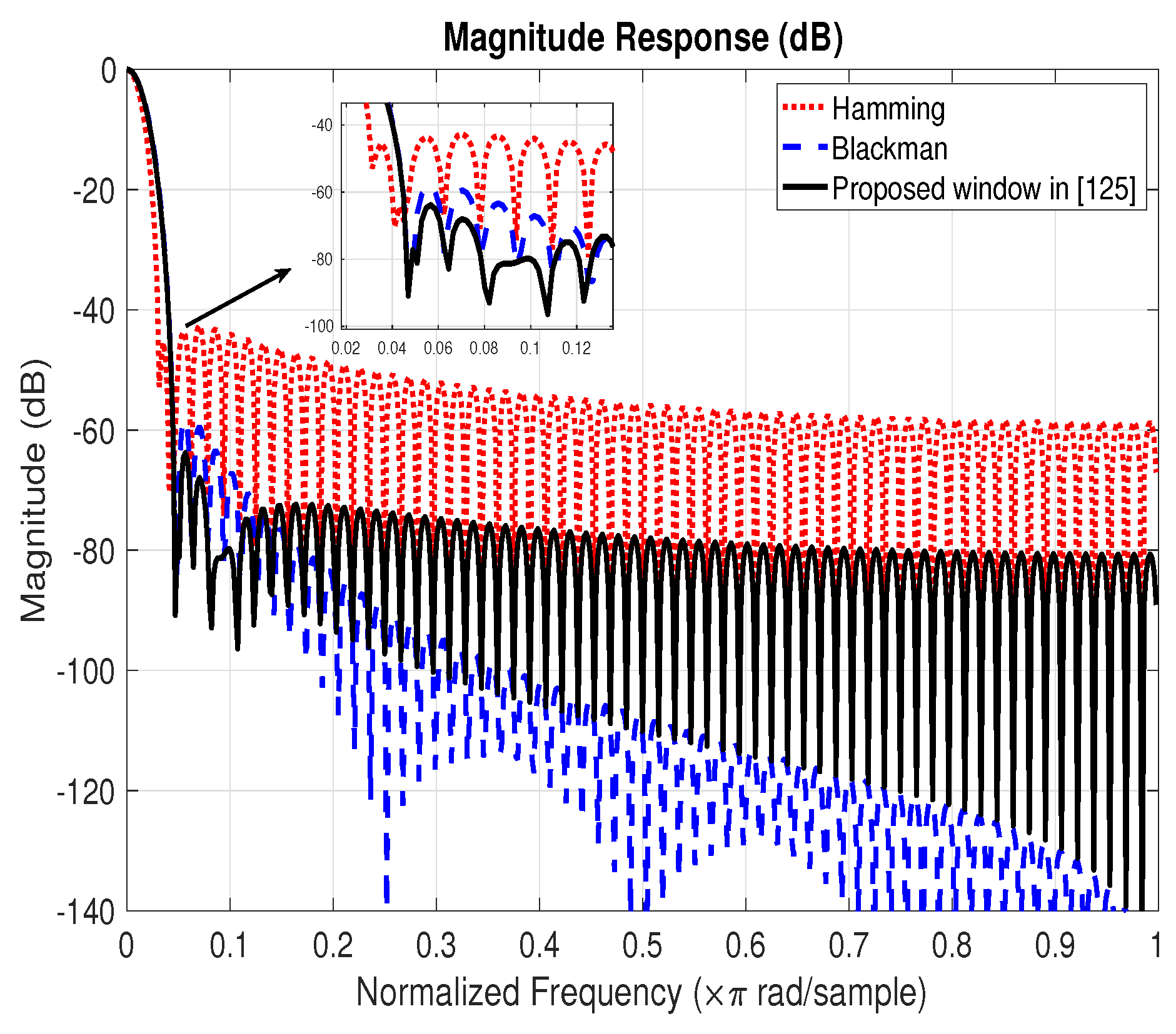
| Jain’s method [125] | Connecting Hamming window and Blackman window by a parameter . | Pros: Best first side-lobe level and spectrum efficiency compared to Hamming and Blackman windows. Cons: Large transition bandwidth. |
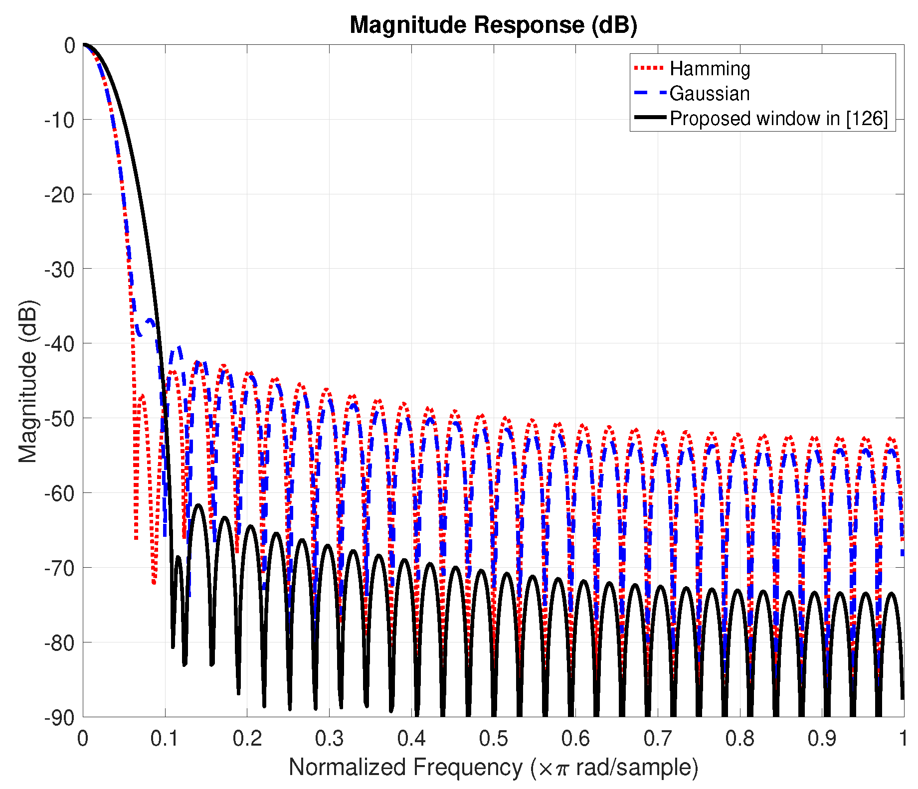
| Kumar’s method [126] | Product of Hamming window and Gaussian window. | Pros: Excellent performance of stopband attenuation compared to Hamming and Gaussian windows. Cons: Under the same parameter setting, the width of main-lobe will increase. |
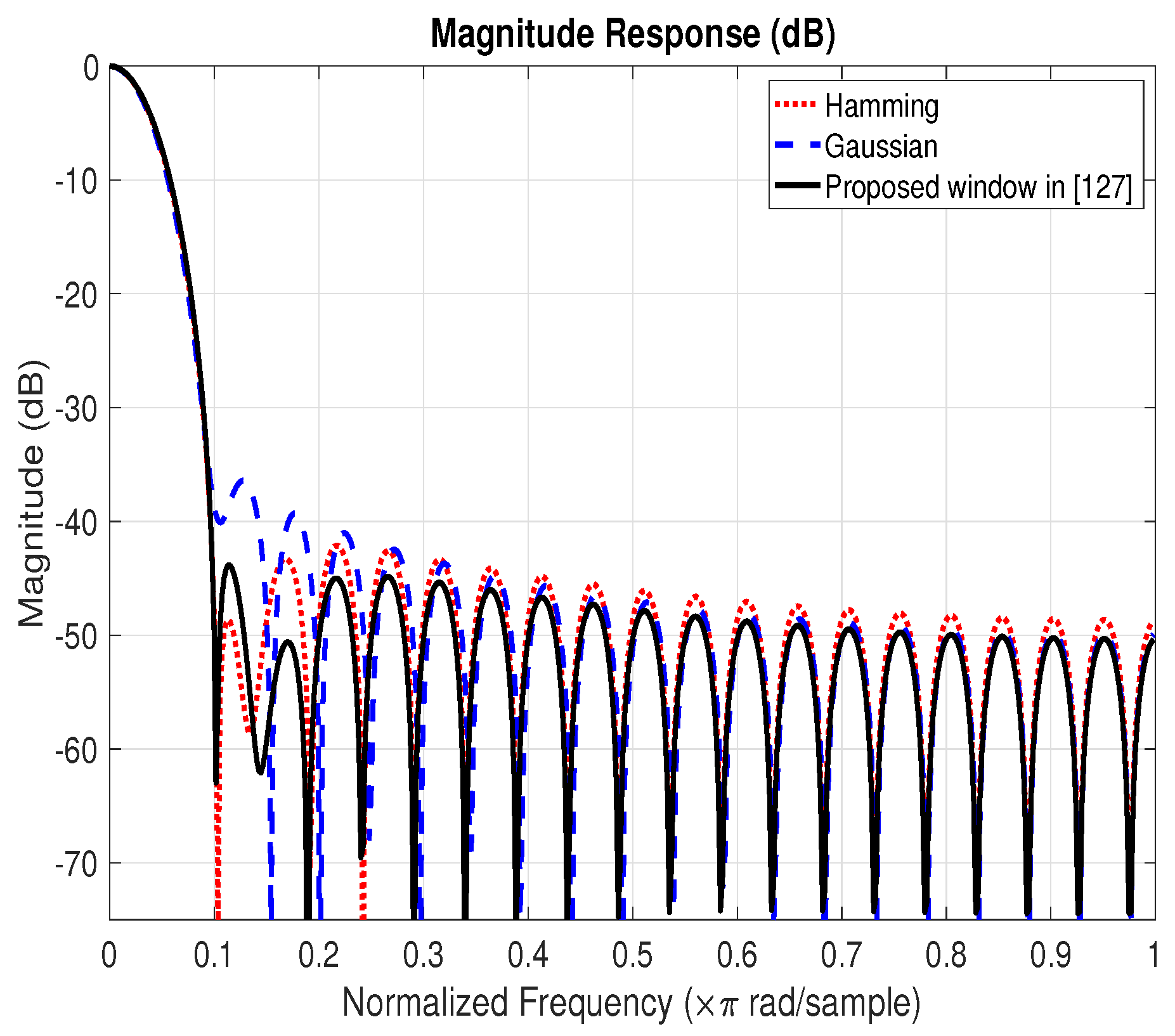
| Mottaghi-Kashtiban’s method [127] | Design a four-semester raised cosine window by optimizing window parameters. | Pros: Narrower main-lobe under similar conditions compared to Hamming window. Cons: Although with improved performance of stopband attenuation, the performance gain is inconspicuous. |
| Rakshit’s method [129] | A window function combining tangent hyperbolic function and weighted cosine series using an adjustable parameter . | Pros: Higher side-lobe roll-off ratio under the same main-lobe width compared to Gaussian window. Cons: Need to constantly adjust the parameters . |
| Martin-Martin’s method [130] | The parameters of a four-term generalized cosine window are optimized on the basis of a given objective function. | Pros: Best performance of signal-to-overall-interference ratio compared to Kaiser and Blackman windows. Cons: High algorithm complexity. |
| GA Algorithm | DE Algorithm |
|---|---|
| Population size = 100 | Population size = 100 |
| Crossover rate = 0.8 | Crossover rate = 0.8 |
| Mutation rate = 0.01 | Scaling factor = 0.8 |
| Generation number = 500 | Combination factor = 0.8 |
| — | Generation number = 500 |
| Methods | Comments | Pros and Cons |
|---|---|---|
| Ababneh’s method [131] | Design the filter using the PSO algorithm. | Pros: Simple and intuitive. Cons: Poor stopband attenuation performance of the filter under low-order conditions. |
| Luitel’s method [132] | Design the filter using the DEPSO algorithm. | Pros: Compared with PSO algorithm, the filter has better convergence consistency. Cons: Improvement of the stopband attenuation is not obvious. |
| Gupta’s method [133] | Design the filter using the RPSO algorithm. | Pros: Compared with PSO algorithm, the filter has better convergence and can avoid falling into local optimum. Cons: Improving the performance of the stopband attenuation is not obvious. |
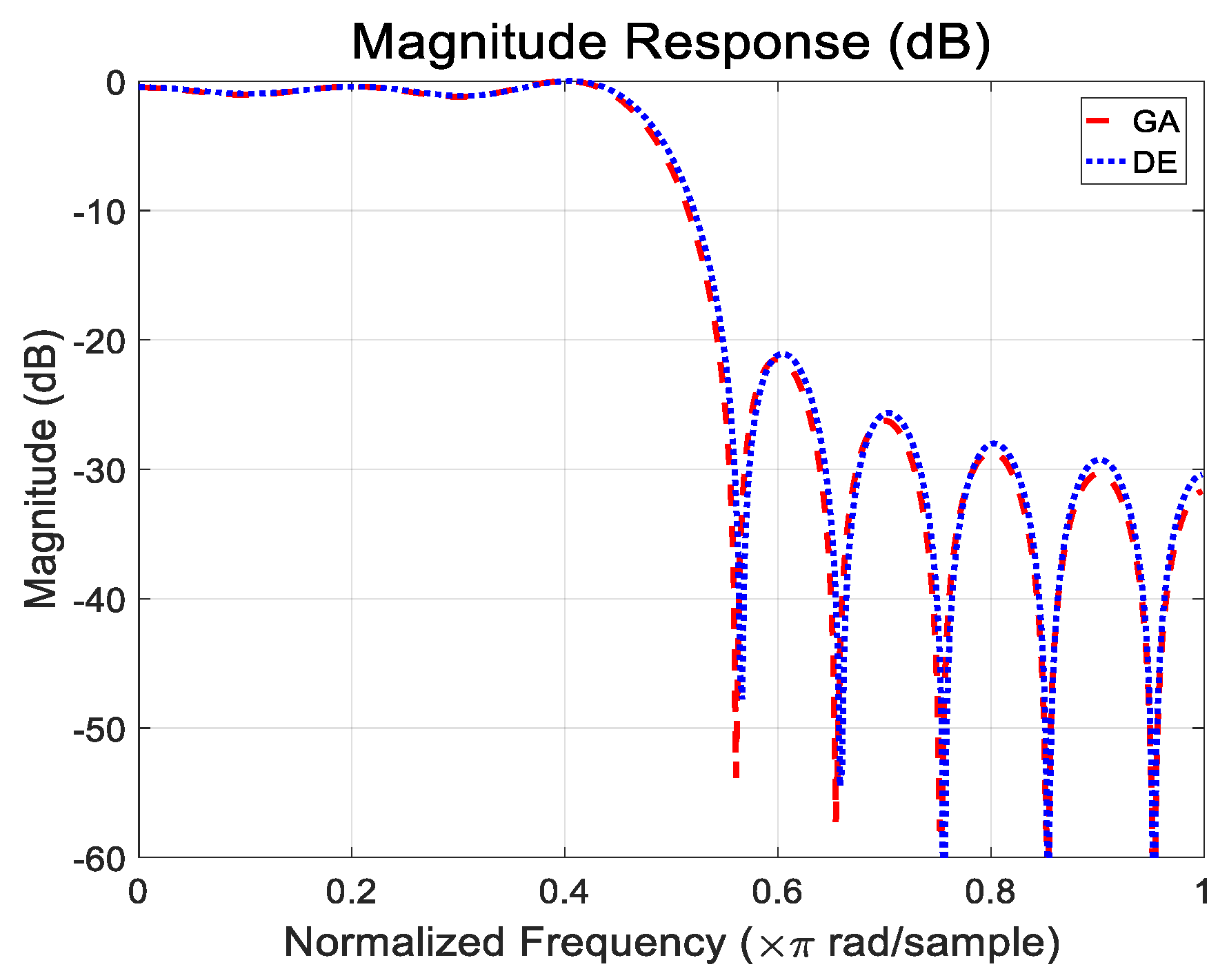
| Li’s method [134] | Design the filter using the GA algorithm. | Pros: Obtain near global optimum solutions. Cons: Slow convergence rate and poor stopband attenuation performance. |
| Karaboga’s method [135] | Design the filter using the DE algorithm. | Pros: Better convergence and acceptable computational complexity compared to GA. Cons: Improvement of the stopband attenuation is not obvious. |
| Chen’s method [98] | Directly optimize filter coefficients. | Pros: Minimize the ISI/ICI and the stopband energy for FBMC modulation. Cons: High computational complexity. |
| Hunziker’s method [136] | An optimization algorithm aiming at minimizing TF resolution. | Pros: Minimize the TF resolution. Cons: High first sidelobe. |
| Dedeoğlu’s method [139] | Design the filter by convex optimization using DIRR algorithm. | Pros: Robust design under the phase and group delay constraints. Cons: Approximated solution. |
| Kobayashi’s method [140] | Minimize the out of band pulse energy through a relaxed QCQP. | Pros: High symbol reconstruction performance and desirable spectral features. Cons: Approximated solution. |
| OFDM | FBMC | GFDM | UFMC | F-OFDM | |
|---|---|---|---|---|---|
| Spectral Efficiency | Medium | High | Medium | High | Medium |
| Out of Band | High | Low | Low | Low | Low |
| Cyclic Prefix | Yes | No | Yes | No | Yes |
| Synchronized Requirement | High | Low | Medium | Low | Low |
| Latency | Short | Long | Short | Short | Short |
| Effect of Frequency Offset | Medium | Low | Medium | Medium | Medium |
| PAPR | High | High | Low | Medium | High |
| Computational Complexity | Low | High | High | High | Medium |
| Short-Burst Traffic | No | No | Yes | Yes | No |
© 2020 by the authors. Licensee MDPI, Basel, Switzerland. This article is an open access article distributed under the terms and conditions of the Creative Commons Attribution (CC BY) license (http://creativecommons.org/licenses/by/4.0/).
Share and Cite
Jiang, L.; Zhang, H.; Cheng, S.; Lv, H.; Li, P. An Overview of FIR Filter Design in Future Multicarrier Communication Systems. Electronics 2020, 9, 599. https://doi.org/10.3390/electronics9040599
Jiang L, Zhang H, Cheng S, Lv H, Li P. An Overview of FIR Filter Design in Future Multicarrier Communication Systems. Electronics. 2020; 9(4):599. https://doi.org/10.3390/electronics9040599
Chicago/Turabian StyleJiang, Lei, Haijian Zhang, Shuai Cheng, Hengwei Lv, and Pandong Li. 2020. "An Overview of FIR Filter Design in Future Multicarrier Communication Systems" Electronics 9, no. 4: 599. https://doi.org/10.3390/electronics9040599
APA StyleJiang, L., Zhang, H., Cheng, S., Lv, H., & Li, P. (2020). An Overview of FIR Filter Design in Future Multicarrier Communication Systems. Electronics, 9(4), 599. https://doi.org/10.3390/electronics9040599