Abstract
To solve the problem of incompatibility and mutual repulsion between a distribution network (DN) and distributed generator (DG), this paper first analyzes the conflicts between current feeder automation (FA) and doubly-fed induction generation (DFIG). Then, a DFIG coordination control strategy compatible with FA is proposed to cause the DFIG operating continuously during fault isolation and power supply recovery. The strategy consists of three aspects: (1) a DFIG islanding active synchronization control technology to support islanding and distant presynchronization control; (2) DFIG senses the status of circuit breakers/tie-switch through generic object oriented substation event (GOOSE) messages to achieve rapid switch of control modes and distant synchronization; (3) tie-switch senses the status of DFIG through GOOSE messages for closing. Finally, the effectiveness of the strategy is validated by multiple sound and detailed time-domain simulation cases. This study indicates future possible development trends and provides a simple and effective strategy for researches in the field of smart grid DN–DG compatibility.
1. Introduction
Distributed generation (DG) is characterized by flexible installation, convenient power supply, and environmental protection. In general cases, a DG is installed near the user to reinforce the reliable power supply and power quality [1]. Therefore, on the basis of a traditional inactive distribution network (DN), DG technology was vigorously developed [2,3,4], and the mixed network became an inevitable tendency of future development of the DN system. However, with the grid-connection operation of large-scale DG, a traditional radial DN with a single power supply is gradually transforming to a grid structure with multiple power supplies, which is accompanied by more and more prominent DN–DG conflicts and problems in the DN [5]. As a whole, the upgrading of active DN to smart DN is hindered by the incompatibility and mutual repulsion between the DN and the DG [5,6]. Henceforth, the topology, operation code, control method, and protection configuration of the traditional DN need to be adjusted to adapt the impact of DG [7].
From the perspective of protection, a traditional DN is generally a radiating structure from substations to users, and is relieved from the long-term impact of fault based on unidirectional power flow design with equipment such as relays, circuit breakers, reclosing devices, sectionalizers, and fuses [8,9]. Nevertheless, the installation of DGs has changed the topology structure of DNs with a possibility of serious problems in the normal operation of protections to traditional DNs, for instance, asynchronous closing, rejected automatic reclosing, unintentional islanding, change of fault current level, blinding of the protective devices, large-scale disconnection from the grid of generator sets, and the maloperation of feeder protection [10,11,12]. Consequently, the reliability of traditional distribution systems is compromised significantly by the integration of DGs in terms of failure of protection coordination [13]. The installation of DG increases the possibility of unintentional islanding, as part of the DN may continue to operate as an islanding when one or more of the circuit breakers on the feeder trip to remove the fault [13]. For the sake of various reasons, including the difficulties in voltage and frequency control, islanding reconnection, poor power quality, personal safety, and the difficulty in removing the arc fault when DGs remain connected to the grid, islanding (not only unintentional islanding) is considered undesirable [14]. DG applies different control modes for grid-connection and islanding; unintentional islanding is likely to be accompanied by the failure of rapid and accurate switching of DG control modes, resulting in the collapse of the islanding system [15]. Furthermore, if the primary generators trip when the DG is not disconnected in time, the existence of bus voltage will endanger the safety of maintenance and repair personnel potentially on the one hand, and affect the accurate judgment of the backup power automatic switching devices on the other hand, resulting in the protection rejecting movement [16]. Moreover, a strong link has been established between islanding and reclosing, because unintentional islanding may lead to asynchronous closing, further damaging the DG and distribution system seriously [8]. In addition, the fault current of a distribution network varies greatly in DG grid-connection and islanding states, and the protection strategy of DG under grid-connection status is not suitable for the islanding state [17].
In recent years, domestic and foreign researchers have put forward various active DN protection strategies aiming to protect the DG and the DN, while protection standards and specifications were developed by the power authorities and international power organizations for DNs involving DGs to enhance the reliability of the DN [18,19]. So far, the mainstream engineering DN-side protection is the fast and non-selective disconnection of all DGs in case of any failure on the feeder or system in any form, to eliminate any possible negative influence on the existing protection [13,20]. In case of a DG in the islanding status, its internal control system will, in the general case, activate the anti-islanding protection mechanism for eliminating the impact on the DN and the self-protection of DG [18,21]. DGs with fault ride through capacity can be removed from the grid after a delay of a limited period in any fault [12]. The impact on the distribution protection can also be avoided by limiting DG output and optimizing DG placement [22,23]. In fact, the capacity and location of DG are subject to the objective natural environment, and may not be allocated at will [24]. Obviously, such protection strategies have weakened the advantage of DGs in improving the power supply reliability and sufficient utilization of energy. Furthermore, the splitting and stopping of DGs may affect the stability of the grid, disadvantage power recovery, and result in additional maintenance costs [13,20]. For a predefined set of grid faults, the wind energy conversion systems (WECS) should remain connected, supplying reactive power, to sustain the network during voltage shortage [25,26]. In addition, some improved protection strategies based on relay protection technology, adaptive protection, the optimization of protection settings, and modification of the fault current level has been proposed successively [6,12], trying to accurately detect, locate, and isolate the faults when the DG is grid-connected or islanded, but there are also shortcomings and limitations. Essentially, these strategies are to solve the problem of coordination between the protection devices, the dynamic changes in the operation modes between the distribution system and DG are not considered, and a DN–DG coordination mechanism is not provided, so it is likely to lead to islanding instability, islanding’s failure to be incorporated into the DN, or even destruction of the existing distribution system and DG.
It should be noted that in case of a fault, the current active DN is conservative in two points in the DN–DG coordination: (1) the DN-side control is mainly to temporarily eliminate the “DG”, a protection strategy under the traditional DN concept; (2) the DG-side control focuses on the DG and for the purpose of “self-protection” without consideration to the installation environment, and in a deficiency of ideas on technology docking and integration. The current standards and operation guides on the DG integrating into the DN are based on the existing technology level, while the technical route and final goals of smart grid will surely and gradually break through those restrictions to achieve the smart integration of DG and DN [24,27]. In the past decades, the doubly-fed induction generator (DFIG) was at a leading position in the market. To adapt to the development tendency of a smart grid, it is necessary to study the DN–DG coordination and control strategy for DFIG integrating into the DN. Therefore, on the basis of analyzing DFIG and typical feeder automation (FA) contradictions, this paper proposed a DN–DG coordination control strategy to make sure the DFIG operates continuously during fault isolation and power supply recovery conducted by FA, rather than shutdown and restart.
The contributions of the study can be summarized as follows:
- (1)
- A DFIG islanding active synchronization control technology (IAS) referring to the ideas of traditional synchronous generator grid connection is proposed to support islanding and distant presynchronization control.
- (2)
- A coordination control strategy between DFIG and circuit breakers in the whole DN is given in which the DFIG senses the status of circuit breakers through generic object oriented substation event (GOOSE) messages to achieve the rapid switch from grid-connection status to islanding status.
- (3)
- A coordination control strategy between DFIG and tie-switch in an arbitrary place is proposed in which the DFIG senses the status (synchronous status/opening and closing status) of the tie-switch through GOOSE messages to achieve distant synchronization and safe switching from short-time islanding status to reconnection status, and tie-switch senses the status of DFIG through GOOSE messages for closing.
The other sections in this paper are structured as follows. Section 2 summarizes the active DN system studied in this paper and analyzes the conflicts between the current FA protection logics and DFIG integration. Section 3 gives a solution to the compatibility between the DN and the DFIG. Section 4 describes the DFIG IAS in details. Section 5 specifies the strategy for DN–DG coordination and control. Section 6 exhibits the results of simulations under different scenes. Section 7 includes the conclusions.
2. Analysis of Specific Problems
2.1. System under Study
Modern DNs adopt closed-loop design and open-loop operation to achieve flexible and reliable operations. Accordingly, an active DN as shown in Figure 1 is studied in this paper.
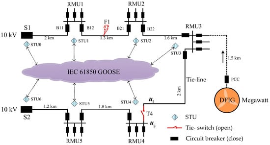
Figure 1.
Distribution system under study.
The primary system is a typical “hand-in-hand” ring network structure with S1 and S2 as the outlet switches by both sides of the substation and interconnected through the ring main unit (RMU) through two feeders led out from S1 and S2. The tie-line connects RMU3 and RMU4. All the inlet and outlet switches of the RMU are circuit breakers, and the tie-switch T4 is normally open with feeder voltage at a 10 kV level. A megawatt DFIG connects to the DN through RMU3. The secondary system is configured as a typical intelligent distributed FA independent from the overall information from the master stations or slave stations, and exchanges fault information by peer-to-peer communication through smart terminal units (STUs), to realize fast location, the isolation of feeder faults, and service restoration [28,29,30]. The communication network supports optical fiber Ethernet structures according to IEC 61850, while the STUs at the substations and the RMUs communicate with each other through GOOSE, which is a fast and reliable message communication mechanism [31,32].
2.2. Feeder Automation Protection Logics
Then, a permanent short-circuit fault happens at F1 of the DN (without consideration to the DFIG), the FA acts according to following logics: STU1 and STU2, through GOOSE peer-to-peer communication, exchanges fault information to locate the fault at the feeder section between circuit breakers B12 and B21. STU1 and STU2 respectively control B12 and B21 for tripping to isolate the fault at F1; after confirming the tripping of B12 and B21, STU1 issues a GOOSE message of successful fault isolation (SFI); as the SFI is received, the STU4 controls T4 for closing to recover the power supply of non-faulty feeder section. Accordingly, without considering the DFIG, FA can automatically locate and isolate the fault, and recover the power supply.
2.3. Conflicts between Feeder Automation and DFIG
Traditionally, DFIG is controlled by the P/Q (active/reactive power control) mode for grid-connection status and V/F (constant voltage/frequency control) mode for islanding status [33,34]. Therefore, DFIG works on continuous grid-connection status or islanding status at present without switching between the two modes. There are few DFIGs that are capable of operating under the two states. Furthermore, the DFIG is located comparatively remote from the DN (several kilometers in general cases), and the tie-switch is flexibly positioned, requiring a distant synchronous grid-connected process for a DFIG island in-grid connection through a tie-switch, which makes this new mode essentially different from the traditional local synchronous grid-connection technology of DFIG. Again, the existing GOOSE fast communication mechanism, in essence, works by the repeated transmission of state messages and fails to achieve the real-time transmission of a remote sinusoidal quantity, while the sampled value (SV) is not an economic and reliable solution for the DN.
For those reasons, when the DFIG is connected to the DN (Figure 1), two conflicts are expected between FA and DFIG to make sure that the DFIG supplies power to partial local loads without quick disconnection and safe reconnection in coordination with the remote tie-switch after the circuit breakers trip and isolate the fault. Conflict 1: a series of opening and closing state messages of circuit breakers, at the discretion of FA, cannot be “notified” to DFIG timely, resulting in the latter’s failure to adapt to the topology changes of the grid; DFIG cannot adjust its control modes timely for the purpose of fast switching between the grid-connection and islanding. Conflict 2: the information channel and message protocols of the DN do not support the distant synchronization function to transform the DFIG status from islanding to grid-connection. The two conflicts are the main reason for the incompatibility and mutual repulsion between DFIG and FA, and hinder the upgrading from an active distribution network to a smart distribution network.
3. Feasible Solution
A megawatt wind turbine has a comparatively larger inertia, and a large amount of mechanical energy can be stored in wind wheels and shafts. At the same time, a direct-current capacitor can also act as an energy storage link. Therefore, DFIG can provide power to local partial loads, to maintain the stability of the islanding system. The purpose of this paper to achieve the continuous operation of DFIG when the fault is isolated and the power supply is restored by FA and the smart integration of the DN–DFIG. In such a process, the DFIG shall be capable of switching between grid-connection and islanding quickly and operating stably, while synchronization conditions are created at the remote tie-switch automatically; then, the tie-switch can be closed safely, after which the DFIG can recover to the grid-connection status. To achieve those advantages, a solution including DFIG IAS to support islanding and distant presynchronization control, and a DN–DG coordination control strategy based on FA/GOOSE to achieve the smart capability of DFIG and FA are proposed, as shown in the following two sections.
4. DFIG Islanding Active Synchronization Control Technology
Traditionally, the DFIG islanding controlled by V/F requires no connection to the grid; therefore, it is not capable of creating the synchronization conditions. The grid-connection control of DFIG is locally synchronous on the basis of real-time sinusoidal voltage signals on both sides of point of common coupling (PCC) [35]. In this paper, DFIG islanding is unable to receive the real-time voltage sinusoidal signals on both sides of T4 at a remote distance, so a new technology that can support DFIG islanding and actively create distant synchronization conditions is in urgent demand. For this purpose, a DFIG IAS consisting of islanding control technology and active synchronization control technology is proposed.
4.1. Islanding Control Technology
A typical DFIG system is indicated in Figure 2. The wind energy captured is transformed into rotary mechanical energy by the wind wheels, and then delivered to DFIG via the gearbox shafts [36]. The stator connects to the grid in a direct manner, while the rotor is through the “back-to-back” converter. A constant DC bus voltage is maintained by the grid-side converter (GSC), while the rotor-side converter (RSC) regulates the excitation voltage of the rotor to realize DFIG grid connection and power generation. With GE 1.5MW DFIG as an example, a study is carried out in this paper [37]. The system consists of mechanical and electrical controls. Mechanical control further covers pitch, pitch compensation, and torque, while the electrical control involves the GSC side and the RSC side.
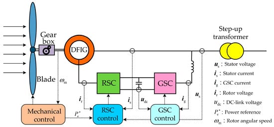
Figure 2.
Doubly-fed induction generation (DFIG) system.
When the rotor follows motor convention and the stator applies generator convention, the basic equation for describing the DFIG system in the frame can be expressed as:
where, , , and represent the axis components of stator’s voltage and current respectively, , , and the axis components of rotor’s voltage and current respectively, , , and the axis component of the magnetic linkage of the stator and the rotor respectively, and the resistance of the stator and the rotor, respectively; and and the synchronous angular velocity and rotor angular velocity, respectively.
The IAS proposed in this paper aims at RSC-side control. The basic control structure of the GE 1.5 MW DFIG [37] for the mechanical part is adopted, while the GSC-side control still follows the typical vector control strategy based on phase-locked loops (PLL) [38]. The maximum power point tracking (MPPT) of the wind turbine [37] is as follows:
where is the reference angular velocity of the wind turbine, and is the actual output electromagnetic power (active power). Therefore, in the MPPT, the speed of the wind turbine under the islanding mode depends on the load to prevent the speed of the wind turbine out of control.
The islanding control technology proposed in this paper is based on the P/Q control structure. First is a brief introduction to the typical P/Q control technology, which adopts a dual-loop control structure consisting of the current inner loop and the power outer loop, where the controller of the current inner loop is:
The controller of the power outer loop is:
where and are the proportional and integral coefficients of the PI (proportional-integral control) controller, respectively. is the rotor self-inductance, and is the mutual inductance. U is the amplitude of the grid voltage at PCC. When connected to the grid, the reference angle of stator voltage is obtained by PLL; namely, . The axis and the axis components of the rotor are the active power and reactive power components, respectively.
To make sure that the stator voltage can track the reference voltage quickly and accurately and reduce the impact of modes switching, a P/Q-based dual-loop control structure is also used in the islanding control. The islanding current inner loop controller adopts Equation (4), and the islanding voltage outer loop controller is designed as follows:
where the reference value of the stator voltage is fixed according to the equation of and . Obviously, the voltage outer loop controller and the power outer loop controller have maintained a unified structure. Both P/Q control and islanding control are largely realized through adjusting the axis component of the rotor, which is advantageous to the safe switching between different states of DFIG (grid-connection/islanding).
Besides, as the DFIG has no supports from the grid voltage under the islanding status, the reference angle of stator voltage in islanding control is obtained according to the following equation:
where is the rated frequency of the grid (). is the reference value generated by the controller, which is likely to cause the voltages due to both sides of the tie-switch not being synchronous. Therefore, synchronous control is required on the basis of islanding control.
4.2. Active Synchronization Control Technology
Referring to the ideas of traditional synchronous generator grid-connection (change the speed of rotor), in this paper, the voltage frequency of the stator is properly changed to cause the relative movement between the DFIG islanding voltage and the grid voltage , so as to create distant synchronization conditions actively. The rotor speed and system frequency of DFIG are mutually decoupled. Therefore, the DFIG IAS proposed in this paper is shown in Figure 3.
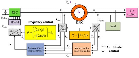
Figure 3.
DFIG islanding active synchronization control technology.
The proposed IAS consists of amplitude control and frequency control. The amplitude control adopts a dual-loop control structure based on Equations (4) and (6); the frequency control is realized by proper change to the rotor excitation rotation angle , which is in the form of:
where is a deviation term, is the deviation frequency and is the rotor’s position angle. By this method, the island voltage frequency equals the sum of and , so that the islanding voltage angular velocity () is not equal to that of the grid (). Consequently, will move relatively to , as shown in Figure 4 ( as the grid voltage amplitude at the tie-switch), where is the angle between and .
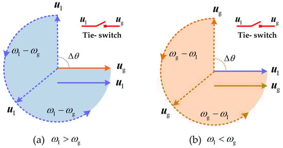
Figure 4.
Principles of distant synchronization.
When is greater than 0, with as the reference, moves faster than , while moves close to at the speed of , as shown in Figure 4a. When is less than 0, with as the reference, moves faster than , while moves close to at the speed of , as shown in Figure 4b. In particular, after synchronization, reduces to 0, and the islanding voltage frequency recovers to , so that both and rotate at the angular velocity of to maintain synchronicity.
5. Coordination Control Strategy
IEC 61850 GOOSE has been extensively applied in DN. The status communication between FA and DFIG by GOOSE is feasible and economic [39,40,41]. This paper proposes a DN–DFIG coordination control strategy based on FA/GOOSE, as shown in Figure 5. Firstly, a GOOSE information channel is established between the DFIG and the FA to achieve the point-to-point rapid states communication between DFIG, circuit breakers and tie-switch. Where,
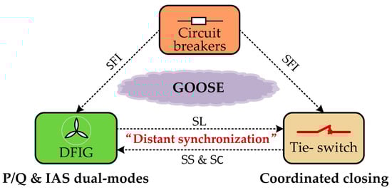
Figure 5.
Framework of the coordination control strategy.
- SFI represents the GOOSE message of successful fault isolation;
- SS represents the GOOSE message of successful synchronization at T4;
- SL represents the GOOSE message of synchronous locking of IAS; and
- SC represents the GOOSE message of successful closing of T4.
The coordination control strategy based on DN–DFIG GOOSE communication consists of “Islanding Stabilization and Distant Synchronization”, and “Synchronous Closing and State Recovery”.
5.1. Islanding Stabilization and Distant Synchronization
Based on the GOOSE transmission mechanism of publish/subscribe, the DFIG in Figure 1 has subscribed all the status information of all the circuit breakers on the two feeders. Therefore, through GOOSE messages, DFIG can, at any time, identify if the DFIG is connected to the grid or off-grid.
When B12 and B21 trip under the control of FA to isolate the fault at F1, the feeder between B21 and DFIG losses supports from the grid voltage, and DFIG has a high possibility of losing stability under the P/Q control. Based on the GOOSE messages communication between DFIG and FA, DFIG can receive SFI messages rapidly and change to IAS control to achieve the rapid switching from grid-connection to islanding. After switching, DFIG is under the islanding state and presynchronization state. It is worth noting that when switching from grid-connection to islanding mode, DFIG takes the operation of zeroing the IAS voltage’s outer loop PI controllers, so that the stator voltage experiences a process of re-establishment, while ensuring that the converter is not overloaded to the maximum extent.
In the process of presynchronization, the synchronization check device at T4 will check the synchronization conditions in situ. After synchronization (), STU4 will issue an SS message to the DFIG for judgment if the remote T4 is synchronous; if not, IAS will be responsible for control; if so, DFIG will reset to “0” immediately to maintain the synchronization status of and at the remote tie-switch T4. Therefore, a distant synchronization method is formed by IAS in cooperation with the GOOSE channel to deliver synchronization status. Obviously, the distant synchronization method proposed in this paper is fundamentally different from traditional local synchronization technologies.
Besides, during creating distant synchronization by IAS, the size of depends on the time delay of the GOOSE information channel, synchronous closing condition, an allowable range of islanding frequency, and distant synchronous adjustment speed. In this paper, it is assumed that the time delay of GOOSE information channel consists of following parts:
- STU interface delay: 3 ms
- Communication delay: 5 us/km
- Potential transformer (PT) delay: 3 ms
- Central processing unit (CPU) processing delay: 50 us
According to the composition of delay, in this paper, is considered as a larger value:
Generally, the synchronous closing condition of tie-switch is:
The allowable range of islanding frequency is:
The synchronous phase error due to is:
The synchronous adjustment time of IAS is:
where the angle between and is .
Obviously, the larger accelerates the synchronization adjustment, but leads to larger synchronous phase error and poor islanding voltage quality; while, on the contrary, a smaller can significantly reduce the synchronization phase error and improve islanding voltage quality, but result in a lower synchronization adjustment speed. After comprehensive consideration, the error frequency in this paper falls in the range of , which makes the islanding frequency , the synchronization phase error no greater than (), and the maximal synchronization adjustment time no longer than 10 s (). It shall be explained that in the actual projects, may be greater than 10 ms. In such a case, a smaller is preferred to make sure that the synchronization phase error satisfies the requirements.
5.2. Synchronous Closing and Status Recovery
In the original FA, STU4 is closed based on the receiving SFI message, which may lead to non-synchronous closing and damage the islanding stability and distant synchronization process. Under the new coordination control strategy, STU4 subscribes the status information of DFIG. When DFIG sets to 0, an SL message is sent. In the meantime, DFIG islanding frequency and grid frequency are the same. STU4 takes control over the closing of T4 after receiving the SFI and SL messages, and confirming the synchronous closing conditions (), to achieve synchronous closing. As T4 closes, IAS is unable to recover the DFIG to the normal grid-connection operation status. Therefore, DFIG will sense the closing status of T4 based on the SC message, and switch back to the P/Q control mode to recover status. Remarkably, when switching from islanding to grid-connection, DFIG takes the output signal of the voltage outer loop as the initial value of the power outer loop to make the inner loop control signal smooth transition, so as to maximize the safety of switching from islanding to reconnection.
6. Case Analysis
Matlab/Simulink is used to establish the active distribution system shown in Figure 1 and the detailed time domain simulation models of DFIG coordination control strategy compatible with FA proposed in this paper. See Appendix A for the DFIG, DN, and controller parameters. The simulation scenarios assume that FA can isolate faults instantaneously, and consider different wind speeds, islanding loads, and values of .
Scenario 1
It is assumed that the B12 and B21 trip at 20 s under the control of FA when the wind speed is 15 m/s (DFIG constant power operation). The islanding load is 1 MW, , and . T4 requires 60 ms to close. Figure 6 and Figure 7 respectively show the changes in the electrical and mechanical quantity at the DN side and the wind turbine side in Scenario 1.
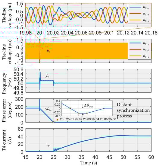
Figure 6.
Major changes of electric quantity at the distribution network (DN) side in Scenario 1.
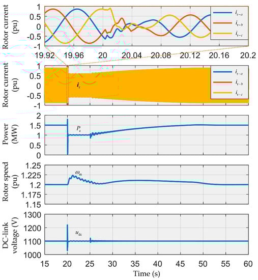
Figure 7.
Major changes of electric and mechanical quantity at the wind turbine side in Scenario 1.
- (1)
- Grid-Connection/Islanding Switching: The circuit breakers B12 and B21 trip at 20 s, and SFI is sent to the DFIG after a delay of 10 ms. Therefore, DFIG switches from P/Q to IAS control at 20.01 s. As shown in Figure 6, in the transient process of DFIG from grid-connection to islanding, due to the changes of control modes and sudden changes in electromagnetic power (0.5 MW), the voltage on the tie-line experienced the process of distortion and rebuilding for about five cycles, after which it stabilizes; at the initial period of tripping, the reaches about 1.25 pu maximally without uncontrollable overvoltage; the waveforms for the voltage frequency of the tie-line, and the phase error of voltages at both sides of the tie-switch flicker transiently as the circuit breakers trip. According to Figure 7, DFIG rotor current experienced the same distortion and rebuilding process as in case of the transient switching from grid-connection to islanding, during which no overcurrent is observed; after transient flickering, the electromagnetic power of the generator maintains at 1 MW; the DC-side voltage reaches a peak of 1220 V during the transient switching without overvoltage; due to the reduction of electromagnetic power;
- (2)
- Distant Synchronization: According to Figure 6 and Figure 7, as DFIG enters the islanding status under IAS control, , , , and maintain relative stability; the rising tendency of is suppressed and gradually reduced, showing a small amplitude of jittering as a whole. The jittering of is mainly due to the slow dynamic response of mechanical control and the sudden change of . The key point is that is controlled at 50.1 Hz, which causes the voltage phase error at both sides of the tie-switch changing from to gradually; synchronization conditions are detected by T4 at 25.01 s, and an SS message is immediately sent; DFIG sets to 0 upon the receipt of a SS message at 25.02 s to maintain the synchronization phase error at about , which obviously complies with the synchronous closing conditions of T4, as shown in Equation (10). Therefore, distant synchronization is achieved.
- (3)
- Islanding/Grid-Connection Switching: DFIG sets to 0 at 25.02 s and sends an SL message at the same time; T4 closes after the receipt of an SL message at 25.03 s, and sends an SC message 60 ms after closing; DFIG switches back to P/Q control at 25.1 s after receipt of the SC message. According to Figure 6, when T4 closes at 25.03 s and DFIG switches back to P/Q control, the current amplitude of the tie-switch is not impacted violently; maintains stability, restores to 50 Hz after small-range fluctuation, and changes to 0 rapidly. In Figure 7, during the reconnection of DFIG, and jitter in a small range due to the fluctuation of in islanding and then gradually rise. The waveform of recovers to a smooth state within 1.225 pu after closing; jitters in a small range, and then stabilizes. Overall, it takes about 26 s for T4 to close when all the electric and mechanical quantities stabilize.
Scenario 2. It is assumed that the B12 and B21 trip at 30 s under the control of FA when the wind speed is 10 m/s (DFIG MPPT operation). The islanding load is 0.8 MW, , and . T4 requires 60 ms to close. Figure 8 and Figure 9 respectively show the changes in the electrical and mechanical quantity at the DN side and the wind turbine side in Scenario 2.
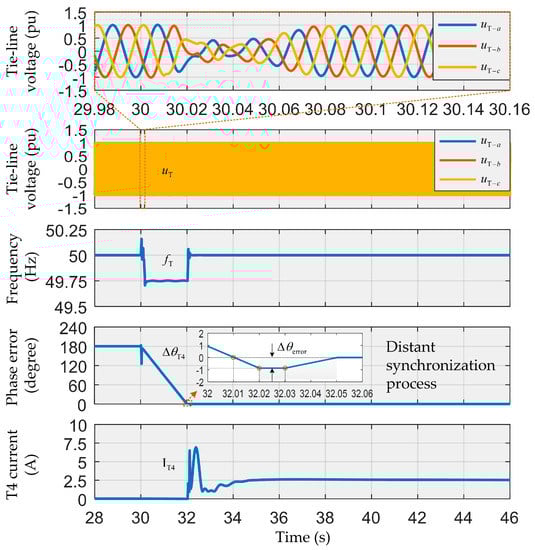
Figure 8.
Major changes of electric quantity at the DN side in Scenario 2.
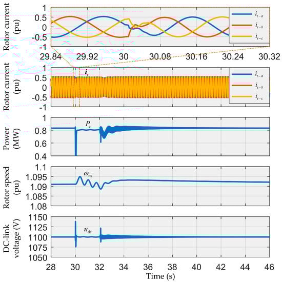
Figure 9.
Major changes of electric and mechanical quantity at the wind turbine side in Scenario 2.
- (1)
- Grid-Connection/Island Switching: After losing voltage support from the feeder at 30 s, DFIG receives an SFI message at 30.01 s, and switches from P/Q to IAS control mode. As shown in Figure 8, in the transient process of DFIG from grid-connection to islanding, due to the changes of control modes and sudden changes in (0.05 MW), experienced the process of distortion and rebuilding for about four cycles, after which it stabilizes; in particular, no large voltage is observed similar to those found in Scenarios 1 and 2 at the initial period of switching, but is more smooth; the waveforms for and flicker more weakly after the circuit breakers trip as compared with the Scenarios 1 and 2. According to Figure 9, experienced the same distortion and rebuilding process as in case of the transient switching from grid-connection to islanding, during which no overcurrent is observed; after transient flickering, maintains at 0.8 MW; the DC-side voltage reaches a peak of 1135 V during the transient switching without overvoltage; due to the reduced change of , the rotor speed rises not so significantly after tripping, but is effectively controlled without stalling under the MPPT in which the rotor reference speed is determined by the load.
- (2)
- Distant Synchronization: According to Figure 8 and Figure 9, in the DFIG islanding under IAS control, , , , and maintain relative stability; shows a small amplitude of jittering around 1.09 pu due to the slow dynamic response of mechanical control and the sudden change of . is controlled at 49.75 Hz, which causes the voltage phase error at both sides of the tie-switch changing from to gradually; synchronization conditions are detected by T4 at 32.01 s, and an SS message is immediately sent; DFIG sets to 0 upon the receipt of an SS message at 32.02 s to maintain the synchronization phase error at about , which obviously complies with the synchronous closing conditions of T4, as shown in Equation (10). Therefore, distant synchronization is achieved.
- (3)
- Islanding/Grid Connection Switching: DFIG sets to 0 at 30.02 s and sends an SL message at the same time; T4 closes after receipt of an SL message at 32.03 s, and sends SC message 60 ms after closing; DFIG switches back to P/Q control at 32.1 s after receipt of the SC message. According to Figure 8, when T4 closes at 32.03 s and DFIG switches back to P/Q control, the maximal amplitude of is under 7.5 A and is not impacted violently; maintains stability, restores to 50 Hz after small-range fluctuation, and changes to 0 rapidly. In Figure 9, during reconnection of DFIG, and jitter in a small range due to the fluctuation of in islanding and then gradually rise. The waveform of recovers to a smooth state within 1.095 pu after closing; jitters in a small range, and then stabilizes. Overall, it takes about 8s for T4 to close when all the electric and mechanical quantities stabilize.
According to the two cases, the larger the absolute value of , the shorter the DFIG is in islanding, and vice versa. Therefore, the absolute value of determines the time of DFIG in islanding. In addition, the sudden change of electromagnetic power will affect the performance of switching between grid-connection and islanding. The larger the sudden change of , the fiercer the waveform change is, and the longer the time required for DFIG recovery after reconnection, and vice versa.
Overall, whether is larger or smaller, positive or negative, whether changes significantly or insignificantly, the time required from the whole process of grid-connection to islanding and islanding to grid-connection is within tens of seconds, indicating that the DN–DFIG coordination strategy proposed in this paper can reduce the DFIG islanding to a short process, which makes it fundamentally different from the traditional long-term islanding.
7. Conclusions
Under the support of GOOSE communication technology, a DFIG coordination control strategy compatible with FA is proposed in this paper, and simulated in details under various scenarios. The following conclusions are made:
- (1)
- DFIG can, on a real-time basis, sense the status of circuit breakers/tie-switch in the DN through 10 ms delay GOOSE to achieve rapid switching of control modes.
- (2)
- Without the real-time sinusoidal voltage at both sides of the tie-switch, DFIG can, on a real-time basis, sense the synchronization status of voltages at both sides of any remote tie-switch and cooperate with the IAS through 10 ms delay GOOSE to achieve distant synchronization of DFIG islanding.
- (3)
- The tie-switch can sense the DFIG control status and achieve synchronous closing through 10 ms delay GOOSE to ensure the safety of DFIG islanding when reconnected to the grid.
- (4)
- The coordination control strategy can reduce the DFIG islanding to a short process (less than 10 s), which, on the one hand, is beneficial to solve the problem of islanding power quality, and on the other hand upgrades the traditional one-way power restoration mechanism from feeder to load to the dual-way power restoration mechanism from DG and feeder to load.
In conclusion, DFIG can achieve the compatibility with typical intelligent distributed FA control logic and continuously operate to further demonstrate its potential to provide new measures for the development of a smart grid through the coordination control strategy proposed in this paper.
Author Contributions
Z.H. contributed to the project idea and the results discussion. P.T. contributed to the specific strategy, theoretical analysis, simulation experiment design, data analysis, results discussion, and conclusions. Z.L. reviewed the final manuscript. All authors have read and agreed to the published version of the manuscript.
Funding
This research was funded by the National Natural Science Foundation of China (51567005), in part by the National Natural Science Foundation of China (61963009), in part by the Guizhou Province Science and Technology Platform and Talent Project of China ([2017]5788/LH Word [2017]7230), in part by the Guizhou Province Science and Technology Plan Project of China ([2018]5615), in part by Collaborative Foundation of Guizhou Province (No.7228[2017]), Platform Talent Project of Guizhou Province (No.5788[2017]).
Conflicts of Interest
The authors declare no conflict of interest.
Nomenclature
| , , & | axis components of stator’s voltage and current |
| , , & | axis components of rotator’s voltage and current |
| , , & | axis component of magnetic linkage of stator and rotor |
| & | Resistance of stator and rotor |
| & | Synchronous angular velocity and rotor angular velocity |
| Reference value | |
| Reference angular velocity of wind turbine | |
| Actual output electromagnetic power | |
| & | Proportional coefficient and integral coefficient of PI controller |
| Rotor self-inductance | |
| Mutual inductance | |
| Grid voltage amplitude at PCC | |
| Grid voltage amplitude at tie-switch | |
| Reference angle of stator voltage | |
| Rotor position angle | |
| Reference angle of stator voltage obtained by PLL | |
| Rated frequency of grid | |
| Islanding voltage frequency | |
| Islanding voltage space vector | |
| Grid voltage space vector | |
| Deviation frequency | |
| Islanding voltage angular velocity | |
| Grid voltage angular velocity | |
| Angle between and | |
| Time delay of GOOSE information channel | |
| Synchronous phase error | |
| Synchronous adjustment time of IAS | |
| SFI | GOOSE message of successful fault islation |
| SS | GOOSE mesage of successful synchronization at T4 |
| SL | GOOSE message of synchronous locking of IAS |
| SC | GOOSE message of successful closing of T4 |
Appendix A

Table A1.
Simulation parameters of case analysis.
Table A1.
Simulation parameters of case analysis.
| Doubly-Fed Induction Generator Parameters | |||
|---|---|---|---|
| Parameter | Value | Parameter | Value |
| 1100 V | 0.0043 Ω | ||
| Rated power | 1.5 MW | 0.0041 Ω | |
| Stator voltage | 690 V | 0.0125 H | |
| Pole pairs | 3 | 0.0153 H | |
| Normal speed | 1.2 pu | 0.0123 H | |
| DC-link capacitor | 20000 uF | Inertia | 1500 |
| Rated frequency | 50 Hz | Friction coefficient | 0.1 |
| Distribution Network Parameters | |||
| Rated voltage | 10 KV | Rated frequency | 50 Hz |
| Line inductance | 0.9347 × 10⁻³ H/km | Line capacitance | 12.86 × 10⁻⁹ F/km |
| Line resistance | 0.01266 Ω/km | ||
| Controllers Parameters | |||
| Parameter | |||
| Controller | |||
| Power outer loop | 0.0001 | 0.045 | |
| Current inner loop | 6 | 150 | |
| Islanding voltage outer loop | 0.01 | 50 | |
References
- Zubo, R.H.A.; Mokryani, G.; Rajamani, H.; Aghaei, J.; Niknam, T.; Pillai, P. Operation and planning of distribution networks with integration of renewable distributed generators considering uncertainties: A review. Renew. Sustain. Energy Rev. 2017, 72, 1177–1198. [Google Scholar] [CrossRef]
- Colmenar-Santos, A.; Reino-Rio, C.; Borge-Diez, D.; Collado-Fernández, E. Distributed generation: A review of factors that can contribute most to achieve a scenario of DG units embedded in the new distribution networks. Renew. Sustain. Energy Rev. 2016, 59, 1130–1148. [Google Scholar] [CrossRef]
- Karimi, M.; Mokhlis, H.; Naidu, K.; Uddin, S.; Bakar, A.H.A. Photovoltaic penetration issues and impacts in distribution network—A review. Renew. Sustain. Energy Rev. 2016, 53, 594–605. [Google Scholar] [CrossRef]
- Adefarati, T.; Bansal, R.C. Integration of renewable distributed generators into the distribution system: A review. IET Renew. Power Gener. 2016, 10, 873–884. [Google Scholar] [CrossRef]
- Roy, N.K.; Pota, H.R. Current Status and Issues of Concern for the Integration of Distributed Generation into Electricity Networks. IEEE Syst. J. 2015, 9, 933–944. [Google Scholar] [CrossRef]
- Blaabjerg, F.; Yang, Y.; Yang, D.; Wang, X. Distributed Power-Generation Systems and Protection. Proc. IEEE 2017, 105, 1311–1331. [Google Scholar] [CrossRef]
- Monadi, M.; Amin Zamani, M.; Ignacio Candela, J.; Luna, A.; Rodriguez, P. Protection of AC and DC distribution systems Embedding distributed energy resources: A comparative review and analysis. Renew. Sustain. Energy Rev. 2015, 51, 1578–1593. [Google Scholar] [CrossRef]
- Kennedy, J.; Ciufo, P.; Agalgaonkar, A. A review of protection systems for distribution networks embedded with renewable generation. Renew. Sustain. Energy Rev. 2016, 58, 1308–1317. [Google Scholar] [CrossRef]
- Nikolaidis, V.C.; Papanikolaou, E.; Safigianni, A.S. A Communication-Assisted Overcurrent Protection Scheme for Radial Distribution Systems with Distributed Generation. IEEE Trans. Smart Grid 2016, 7, 114–123. [Google Scholar] [CrossRef]
- Sajadi, A.; Strezoski, L.; Strezoski, V.; Prica, M.; Loparo, K.A. Integration of renewable energy systems and challenges for dynamics, control, and automation of electrical power systems. Wiley Interdiscip. Rev. Energy Environ. 2019, 8, e321. [Google Scholar] [CrossRef]
- Razavi, S.E.; Rahimi, E.; Javadi, M.S.; Nezhad, A.E.; Lotfi, M.; Shafie-khah, M.; Catalão, J.P.S. Impact of distributed generation on protection and voltage regulation of distribution systems: A review. Renew. Sustain. Energy Rev. 2019, 105, 157–167. [Google Scholar] [CrossRef]
- Norshahrani, M.; Mokhlis, H.; Abu Bakar, A.; Jamian, J.; Sukumar, S. Progress on Protection Strategies to Mitigate the Impact of Renewable Distributed Generation on Distribution Systems. Energies 2017, 10, 1864. [Google Scholar] [CrossRef]
- Manditereza, P.T.; Bansal, R. Renewable distributed generation: The hidden challenges—A review from the protection perspective. Renew. Sustain. Energy Rev. 2016, 58, 1457–1465. [Google Scholar] [CrossRef]
- Xiao, H.F.; Fang, Z.; Xu, D.; Venkatesh, B.; Singh, B. Anti-Islanding Protection Relay for Medium Voltage Feeder with Multiple Distributed Generators. IEEE Trans. Ind. Electron. 2017, 64, 7874–7885. [Google Scholar] [CrossRef]
- Jie, C.; Xin, C.; Zhiyang, F.; Chunying, G.; Yangguang, Y. A Control Strategy of Seamless Transfer Between Grid-connected and Islanding Operation for Microgrid. Proc. CSEE 2014, 34, 3089–3097. [Google Scholar]
- Yongyu, F.; Qi, P.; Zhen, J.; Feng, W. Research on the relay protection control strategy for anti-islanding of distributed generator connected to the power grid of Suzhou. Power Syst. Prot. Control 2017, 45, 94–98. [Google Scholar]
- Hosseini, S.M.; Carli, R.; Dotoli, M. Robust Day-Ahead Energy Scheduling of a Smart Residential User Under Uncertainty. In Proceedings of the 2019 18th European Control, Napoli, Italy, 25–28 June 2019; pp. 935–940. [Google Scholar]
- Vyas, S.; Kumar, R.; Kavasseri, R. Data analytics and computational methods for anti-islanding of renewable energy based Distributed Generators in power grids. Renew. Sustain. Energy Rev. 2017, 69, 493–502. [Google Scholar] [CrossRef]
- Peixin, Y.; Peichao, Z. A Survey on Interconnection Protection of Distributed Resource. Power Syst. Technol. 2016, 6, 1888–1895. [Google Scholar]
- Zidan, A.; Khairalla, M.; Abdrabou, A.M.; Khalifa, T.; Shaban, K.; Abdrabou, A.; El Shatshat, R.; Gaouda, A.M. Fault Detection, Isolation, and Service Restoration in Distribution Systems: State-of-the-Art and Future Trends. IEEE Trans. Smart Grid 2017, 8, 2170–2185. [Google Scholar] [CrossRef]
- Motter, D.; de Melo Vieira, J.C. The Setting Map Methodology for Adjusting the DG Anti-Islanding Protection Considering Multiple Events. IEEE Trans. Power Deliv. 2018, 33, 2755–2764. [Google Scholar] [CrossRef]
- Zhan, H.; Wang, C.; Wang, Y.; Yang, X.; Zhang, X.; Wu, C.; Chen, Y. Relay Protection Coordination Integrated Optimal Placement and Sizing of Distributed Generation Sources in Distribution Networks. IEEE Trans. Smart Grid 2016, 7, 55–65. [Google Scholar] [CrossRef]
- Abdel-Ghany, H.A.; Azmy, A.M.; Elkalashy, N.I.; Rashad, E.M. Optimizing DG penetration in distribution networks concerning protection schemes and technical impact. Electr. Power Syst. Res. 2015, 128, 113–122. [Google Scholar] [CrossRef]
- Kakran, S.; Chanana, S. Smart operations of smart grids integrated with distributed generation: A review. Renew. Sustain. Energy Rev. 2018, 81, 524–535. [Google Scholar] [CrossRef]
- Conficoni, C.; Hashemi, A.; Tilli, A. Recovery of the Voltage-Dip Speed Increase in Wind Turbine by Offline Trajectory Planning. In Proceedings of the IECON 2016—42nd Annual Conference of the IEEE Industrial Electronics Society, Florence, Italy, 23–26 October 2016; pp. 306–312. [Google Scholar]
- Tilli, A.; Conficoni, C.; Hashemi, A. An effective control solution for doubly-fed induction generator under harsh balanced and unbalanced voltage sags. Control Eng. Pract. 2019, 84, 172–182. [Google Scholar] [CrossRef]
- Tian, P.; Li, Z.; Hao, Z. A Doubly-fed Induction Generator Adaptive Control Strategy and Coordination Technology Compatible with Feeder Automation. Energies 2019, 12, 4463. [Google Scholar] [CrossRef]
- Ling, W.; Liu, D.; Yang, D.; Sun, C. The situation and trends of feeder automation in China. Renew. Sustain. Energy Rev. 2015, 50, 1138–1147. [Google Scholar] [CrossRef]
- Chenghong, T.; Zhihong, Y.; Bin, S.; Yajun, Z. A Method of Intelligent Distributed Feeder Automation for Active Distribution Network. Autom. Electr. Power Syst. 2015, 39, 101–106. [Google Scholar]
- Mengyou, G.; Bingyin, X.; Kaijun, F.; Xinhui, Z. Distributed feeder automation based on automatic recognition of real-time feeder topology. Autom. Electr. Power Syst. 2015, 39, 127–131. [Google Scholar]
- Zhu, Z.; Xu, B.; Brunner, C.; Yip, T.; Chen, Y. IEC 61850 Configuration Solution to Distributed Intelligence in Distribution Grid Automation. Energies 2017, 10, 528. [Google Scholar] [CrossRef]
- El Hariri, M.; Youssef, T.; Mohammed, O. On the Implementation of the IEC 61850 Standard: Will Different Manufacturer Devices Behave Similarly under Identical Conditions? Electronics 2016, 5, 85. [Google Scholar] [CrossRef]
- Tanvir, A.; Merabet, A.; Beguenane, R. Real-Time Control of Active and Reactive Power for Doubly Fed Induction Generator (DFIG)-Based Wind Energy Conversion System. Energies 2015, 8, 10389–10408. [Google Scholar] [CrossRef]
- Shukla, R.D.; Tripathi, R.K. A novel voltage and frequency controller for standalone DFIG based Wind Energy Conversion System. Renew. Sustain. Energy Rev. 2014, 37, 69–89. [Google Scholar] [CrossRef]
- Liang, D.; Dan, W.; Lei, G.; Zhouhua, P. Neura network based integeral sliding mode control of doubly-fed induction generator for no-load grid connection. Acta Energ. Sol. Sin. 2017, 38, 3385–3391. [Google Scholar]
- Boubzizi, S.; Abid, H.; El Hajjaji, A.; Chaabane, M. Comparative study of three types of controllers for DFIG in wind energy conversion system. Prot. Control Mod. Power Syst. 2018, 3, 21. [Google Scholar] [CrossRef]
- Miller, N.W.; Sanchez-Gasca, J.J.; Price, W.W.; Delmerico, R.W. Dynamic Modeling of GE 1.5 and 3.6 MW Wind Turbine-Generators for Stability Simulations. In IEEE Power Engineering Society General Meeting (IEEE Cat. No.03CH37491); IEEE: Toronto, ON, Canada, 2003; pp. 1977–1983. [Google Scholar]
- Pena, R.; Clare, J.C.; Asher, G.M. Doubly fed induction generator uising back-to-back PWM converters and its application to variable- speed wind-energy generation. IEE Proc. Electr. Power Appl. 1996, 3, 231–241. [Google Scholar] [CrossRef]
- Andren, F.; Brundlinger, R.; Strasser, T. IEC 61850/61499 Control of Distributed Energy Resources: Concept, Guidelines, and Implementation. IEEE Trans. Energy Convers. 2014, 29, 1008–1017. [Google Scholar] [CrossRef]
- Han, G.; Xu, B.; Fan, K.; Lv, G. An open communication architecture for distribution automation based on IEC 61850. Int. J. Electr. Power 2014, 54, 315–324. [Google Scholar] [CrossRef]
- Yip, T.; Xu, B.; Zhu, Z.; Chen, Y.; Brunner, C. Application of IEC 61850 for distribution network automation with distributed control. J. Eng. 2018, 2018, 993–996. [Google Scholar] [CrossRef]
© 2019 by the authors. Licensee MDPI, Basel, Switzerland. This article is an open access article distributed under the terms and conditions of the Creative Commons Attribution (CC BY) license (http://creativecommons.org/licenses/by/4.0/).