A Hybrid Moth-Flame Fuzzy Logic Controller Based Integrated Cuk Converter Fed Brushless DC Motor for Power Factor Correction


 ,
,
Abstract
1. Introduction
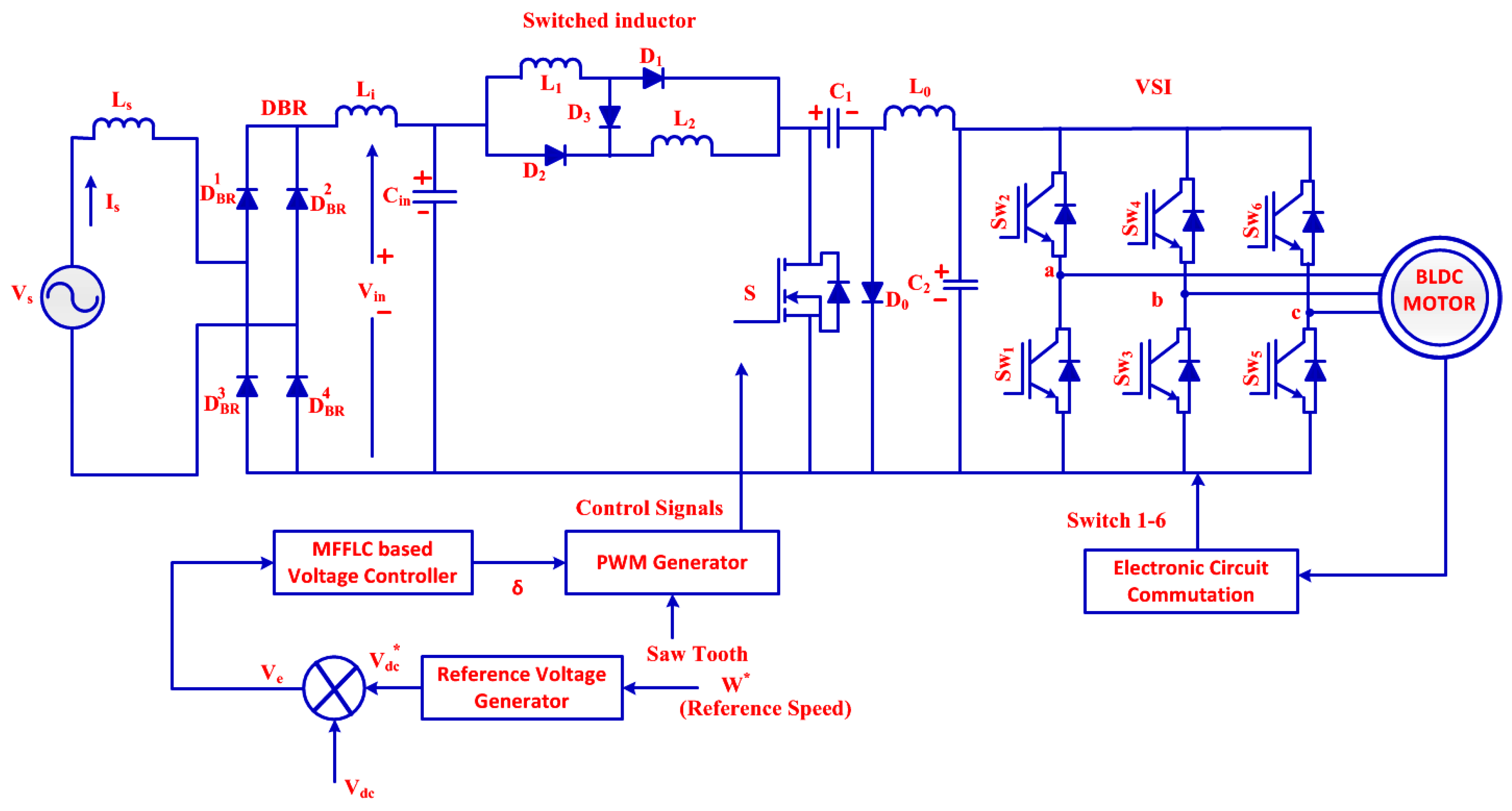
2. PFC of BLDC Motor Utilizing Proposed Technique
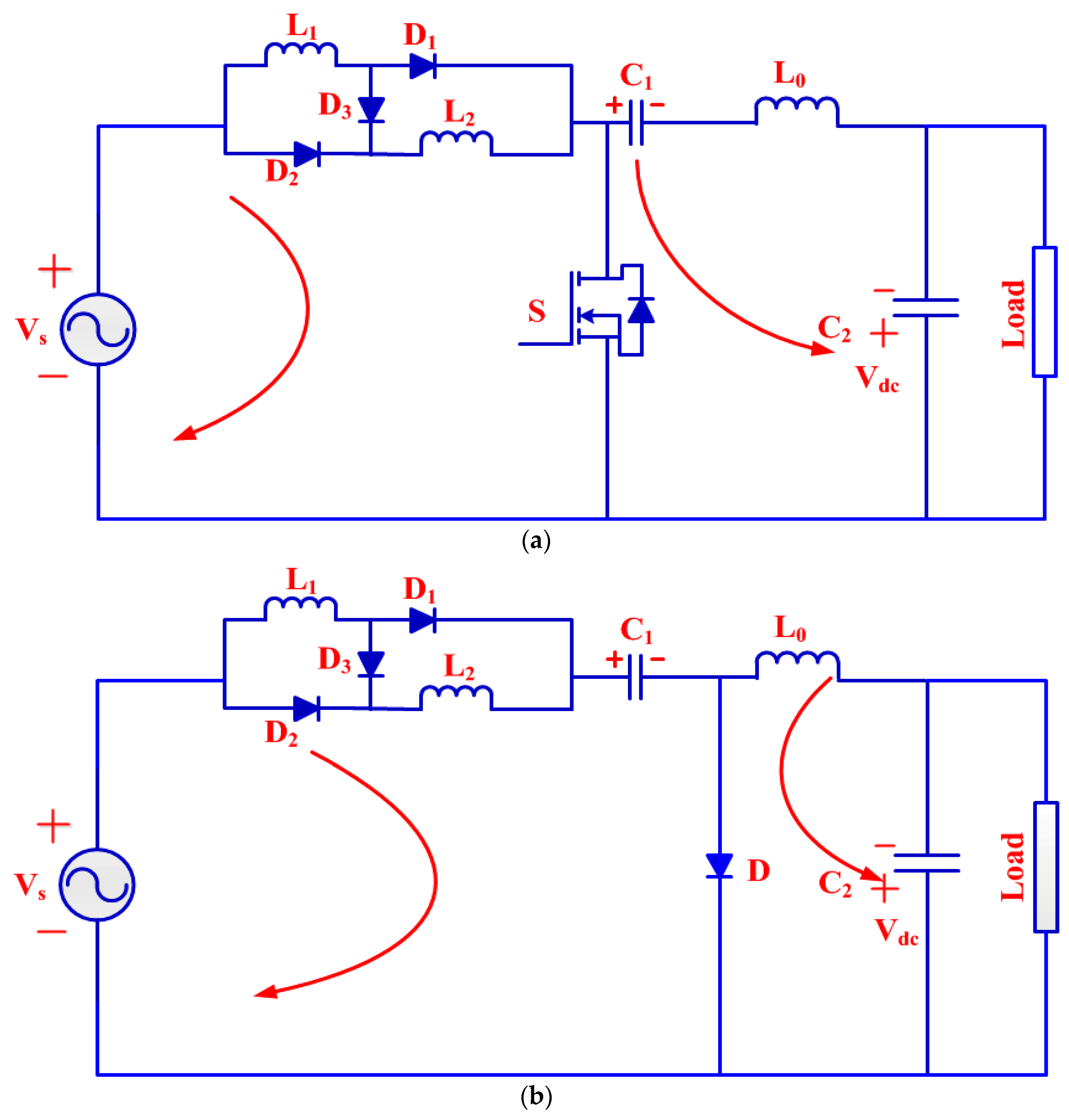
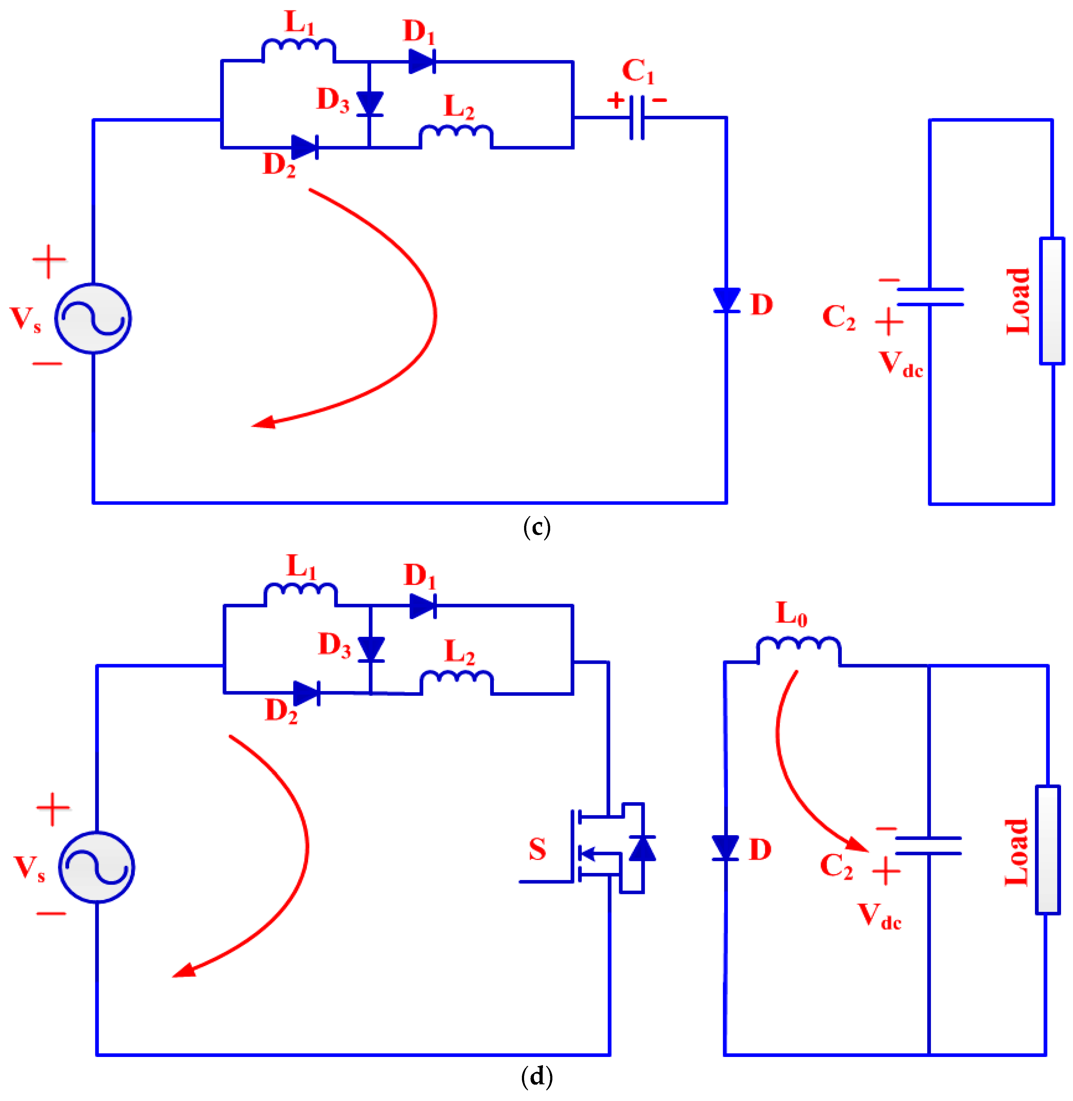
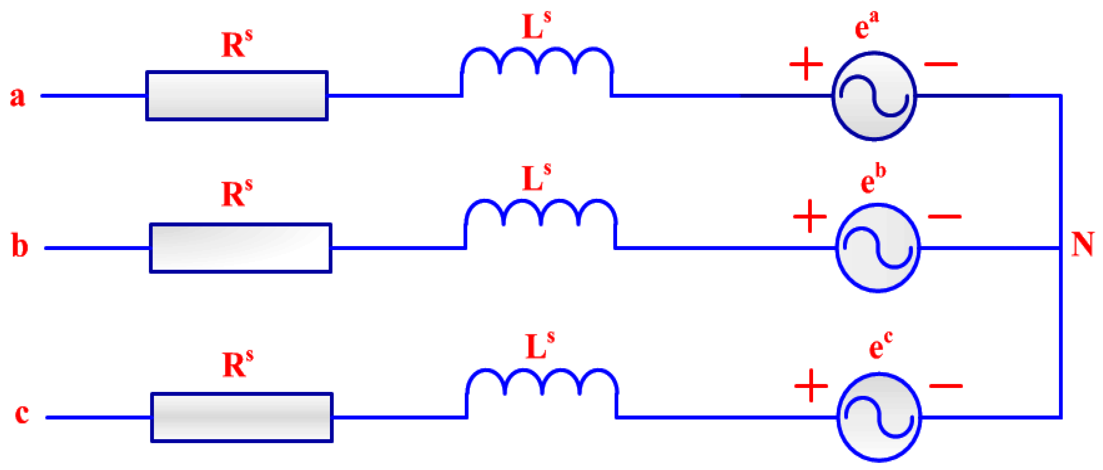
2.1. Modelling Phase
2.2. Controlling Phase
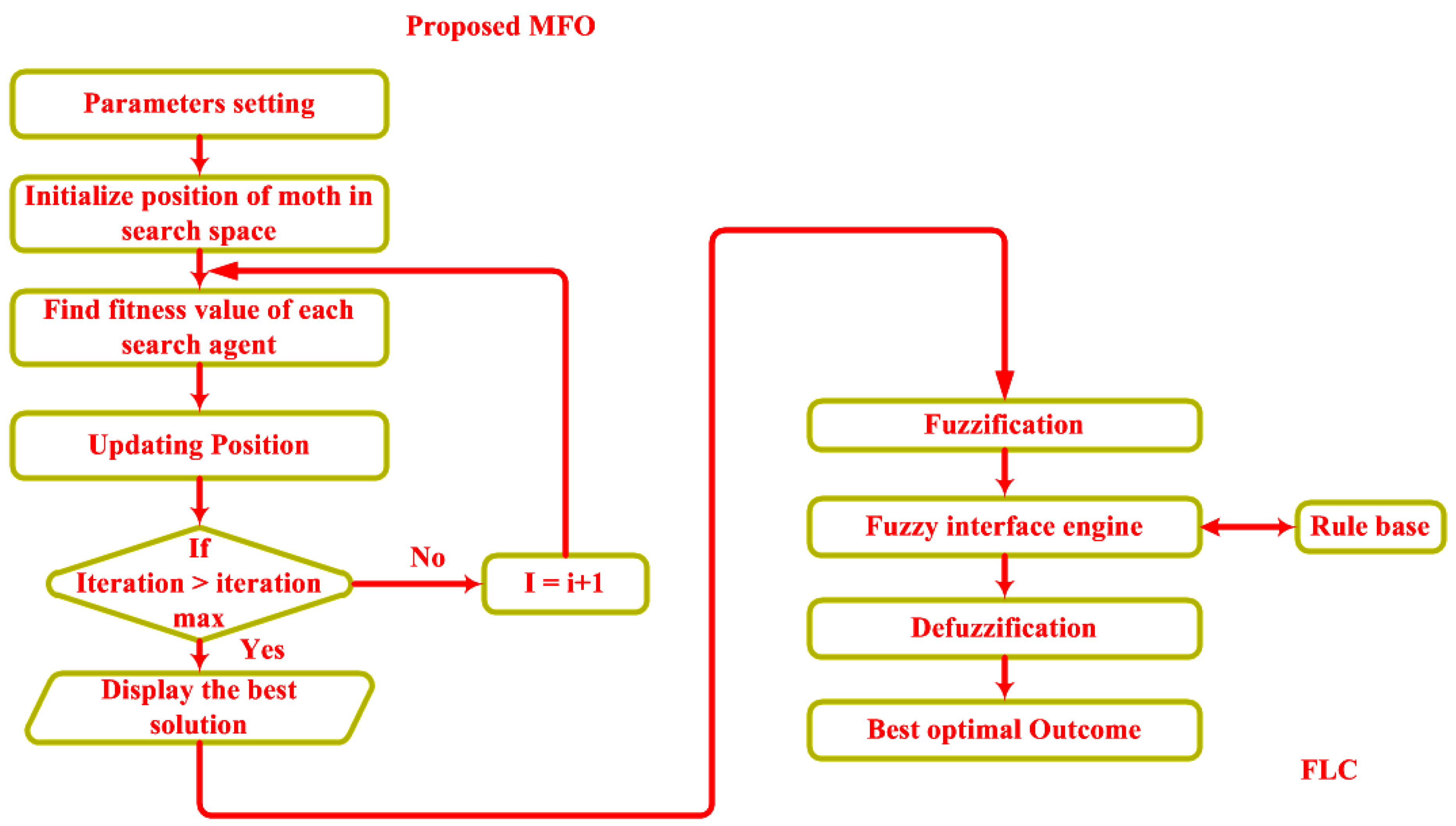
3. Proposed MFFLC Algorithm
3.1. Steps for Proposed MFO Algorithm
3.2. Prediction of Control Signals Using FLC
- (i)
- Fuzzification Process: With the help of membership function selection, it converts crisp to linguistic parameters [32,33]. The error and the change of error are considered as supply parameters of FLC, which is given as follows:where, the reference voltage is , the present output voltage is , and subscripts denotes the initial considered parameters.
- (ii)
- Fuzzy Inference Engine: With the application of If-Then fuzzy rules, decisions are taken as follows:where,, and are subsets and singleton parameters, respectively.
- (iii)
- De-Fuzzification Process: In this method, fuzzy variables are defuzzified and converted to numerical output. It decides membership ability of output parameters. The outcome of the framework database iswhere, is represents the solution of target after fuzzification.
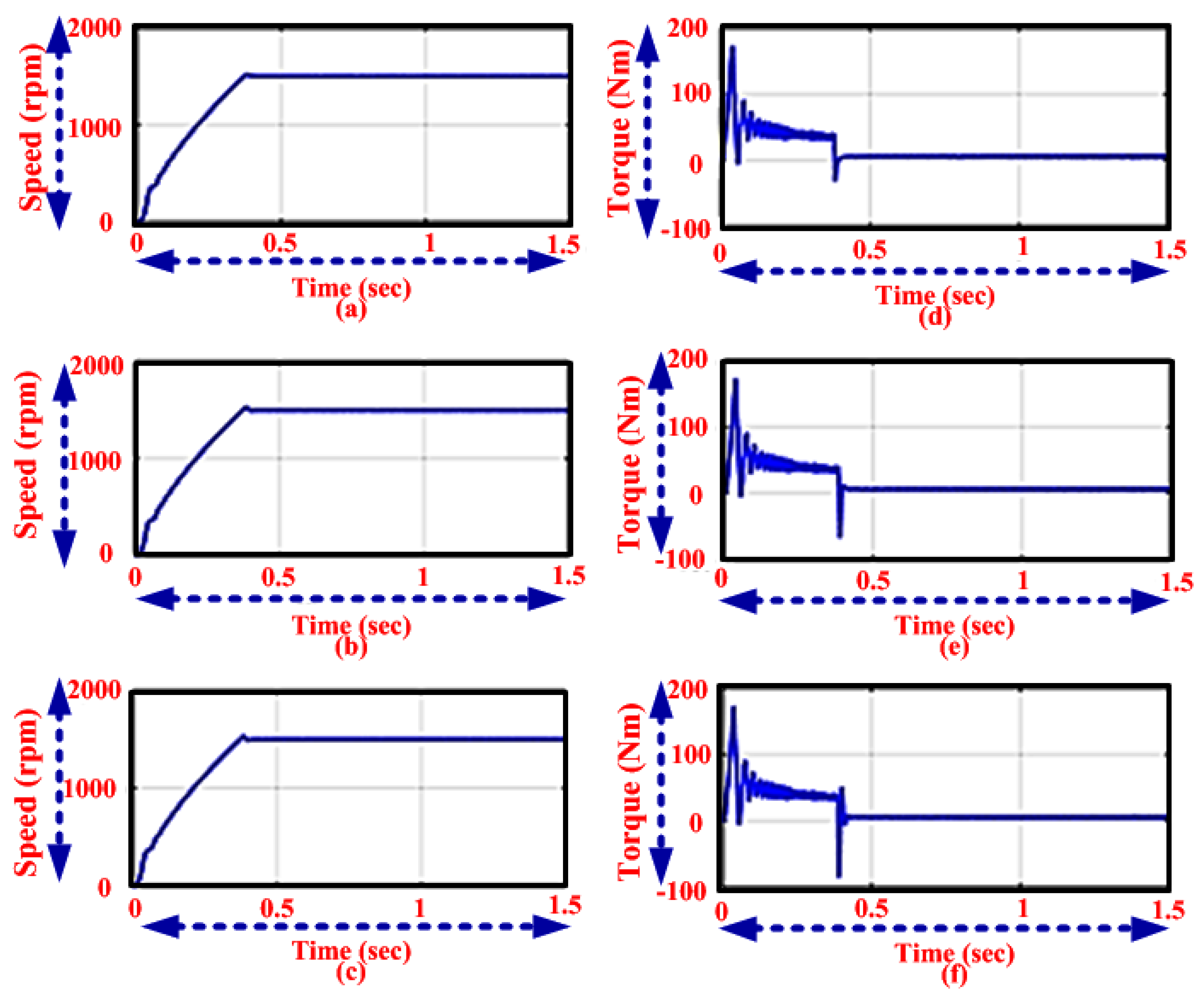
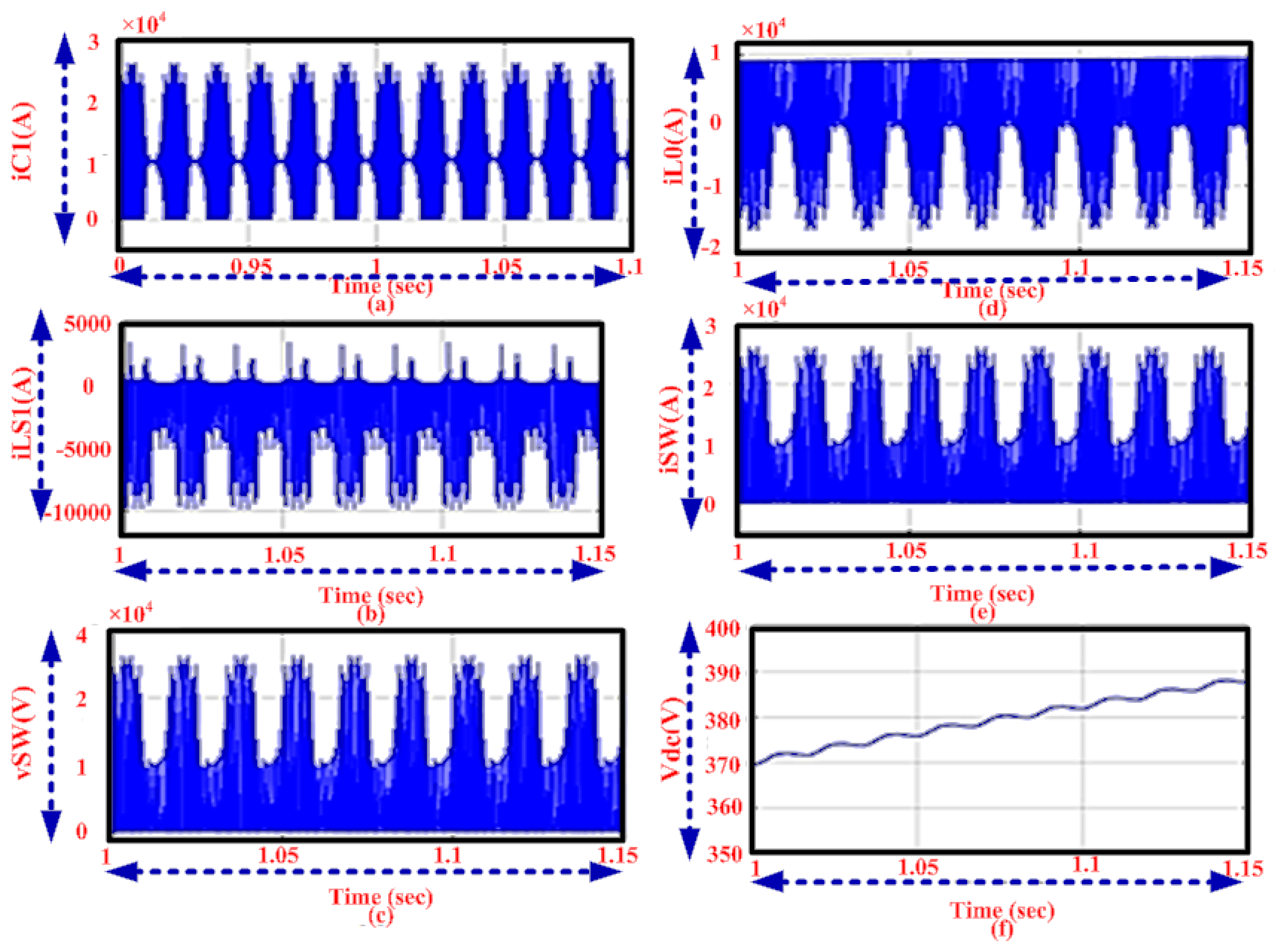
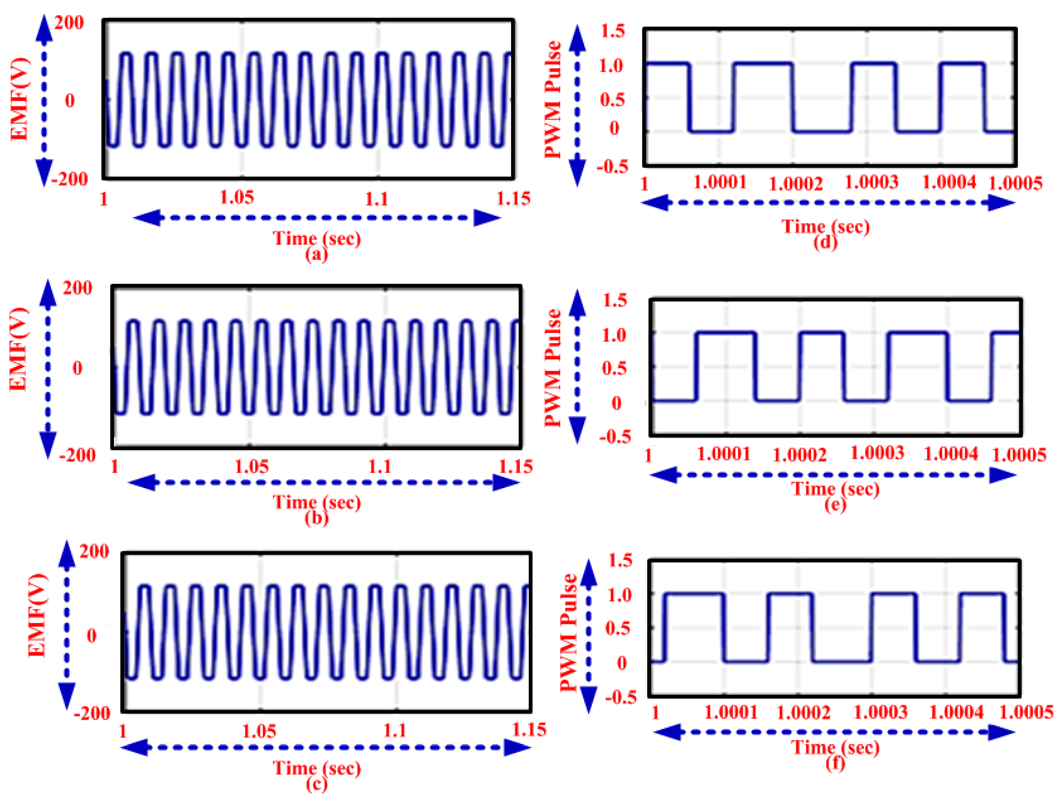
4. Simulated Results and Discussions
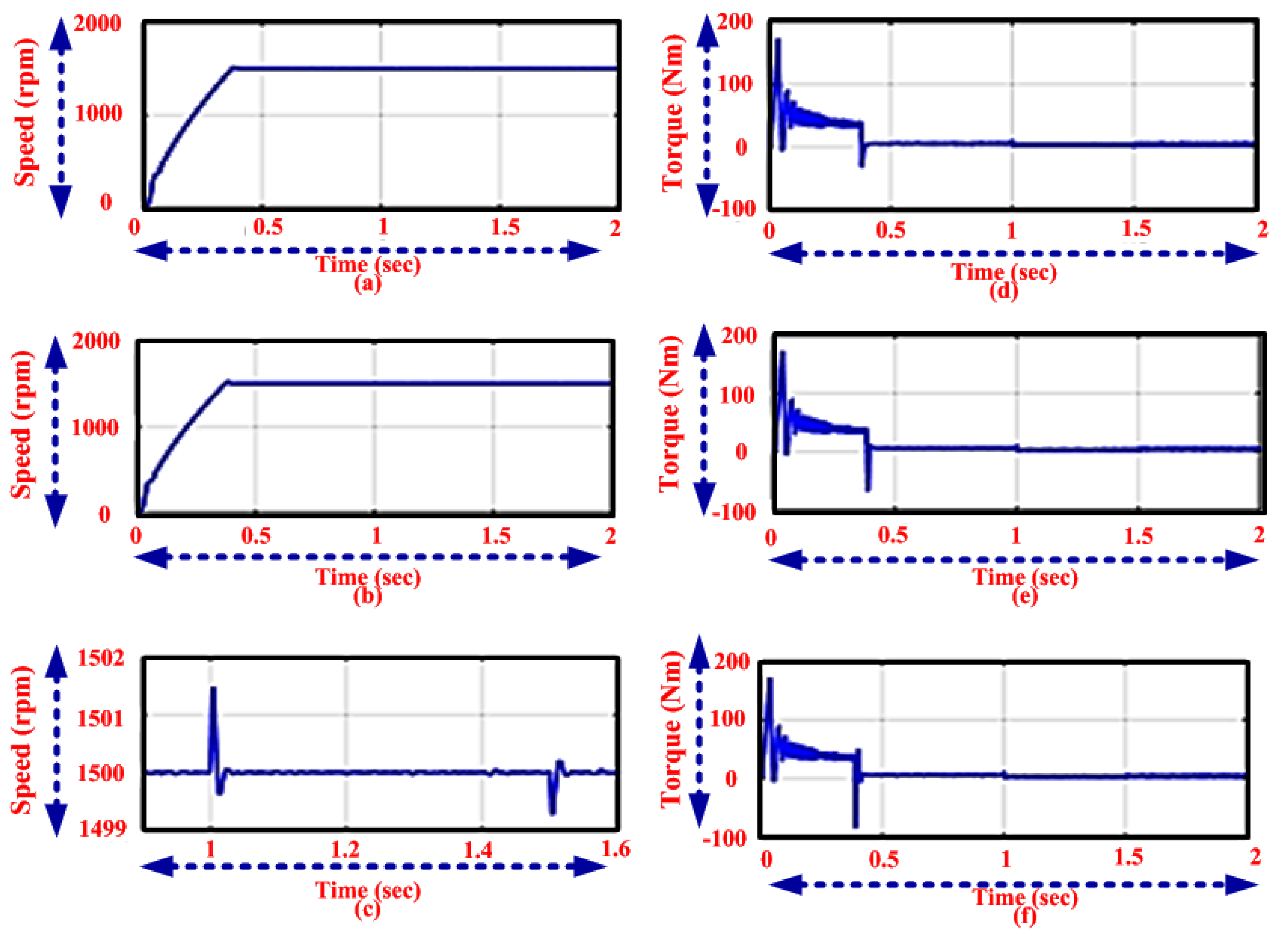
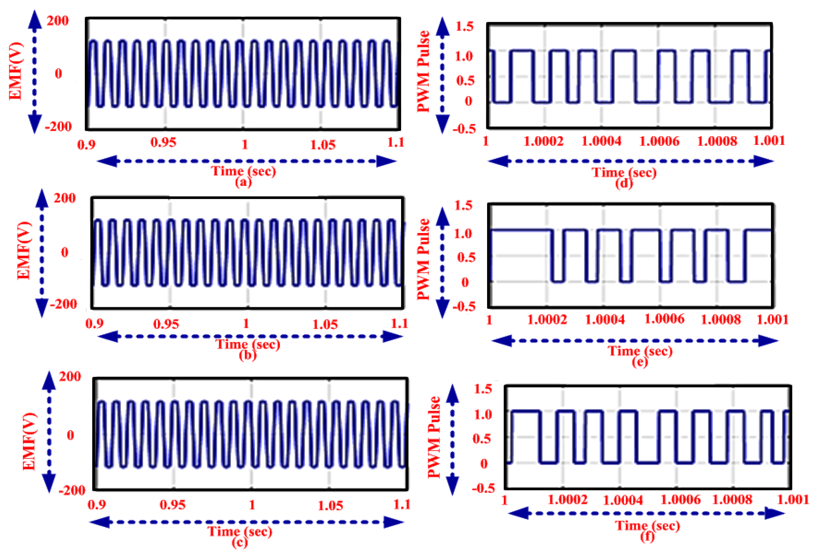
4.1. Test Case 1: Analysis of Constant Speed and Torque
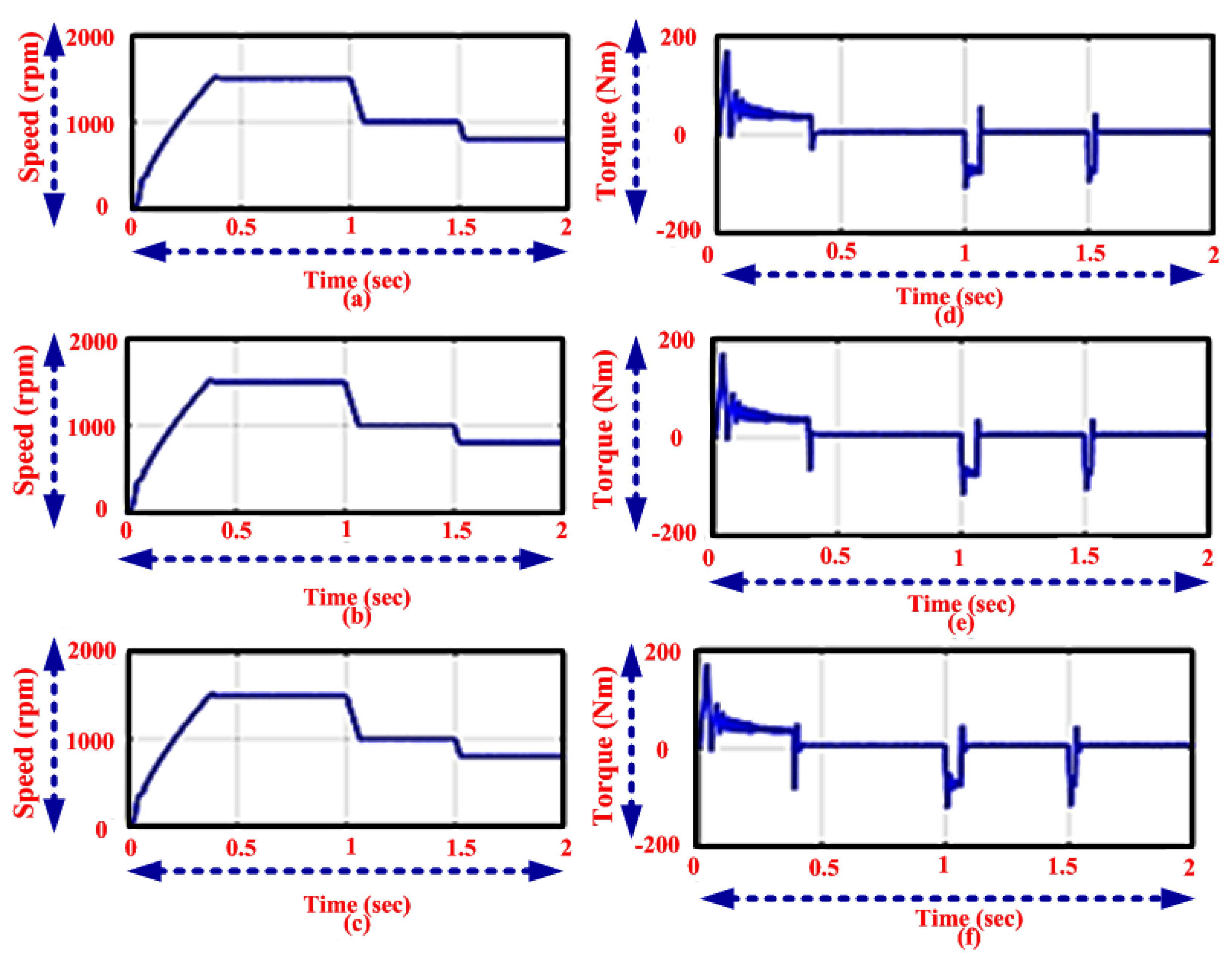
4.2. Test Case 2: Analysis of Constant Torque with Speed Variation
4.3. Test Case 3: Analysis of Torque Variation with Constant Speed
5. Conclusions
Author Contributions
Acknowledgments
Conflicts of Interest
References
- Priyadarshi, N.; Padmanaban, S.; Mihet-Popa, L.; Blaabjerg, F.; Azam, F. Maximum Power Point Tracking for Brushless DC Motor-Driven Photovoltaic Pumping Systems Using a Hybrid ANFIS-FLOWER Pollination Optimization Algorithm. Energies 2018, 11, 1–16. [Google Scholar] [CrossRef]
- Ibrahim, H.E.A.; Hassan, F.N.; Shomer, A.O. Optimal PID control of a brushless DC motor using PSO and BF techniques. Ain Shams Eng. J. 2014, 5, 371–398. [Google Scholar] [CrossRef]
- Niapour, S.A.KH.M.; Tabarraie, M.; Feyzi, M.R. A new robust speed-sensor less control strategy for high-performance brushless DC motor drives with reduced torque ripple. Control Eng. Pract. 2014, 24, 42–54. [Google Scholar] [CrossRef]
- Masmoudi, M.; Badsi, B.E.; Masmoudi, A. Direct Torque Control of Brushless DC Motor Drives with Improved Reliability. IEEE Trans. Ind. Appl. 2014, 50, 3744–3753. [Google Scholar] [CrossRef]
- Sheng, T.; Wang, X.; Zhang, J.; Deng, Z. Torque Ripple Mitigation for Brushless DC Machine Drive Systems Using One-Cycle Average Torque Control. IEEE Trans. Ind. Electr. 2015, 62, 2114–2122. [Google Scholar] [CrossRef]
- Lu, H.; Zhang, L.; Qu, W. A New Torque Control Method for Torque Ripple Minimization of BLDC Motors with Un-Ideal Back EMF. IEEE Trans. Power Electr. 2008, 23, 750–758. [Google Scholar] [CrossRef]
- Shi, T.; Guo, Y.; Song, P.; Xia, C. A new approach of minimizing commutation torque ripple for brushless DC motor based on DC–DC converter. IEEE Trans. Ind. Electr. 2010, 57, 3483–3490. [Google Scholar] [CrossRef]
- Fang, J.; Zhou, X.; Liu, G. Precise Accelerated Torque Control for Small Inductance Brushless DC Motor. IEEE Trans. Power Electr. 2013, 28, 1400–1412. [Google Scholar] [CrossRef]
- Potnuru, D.; Chandra, K.P.B.; Arasaratnam, I.; Gu, D.W.; Mary, K.A.; Ch, S.B. Derivative-free square-root cubature Kalman filter for non-linear brushless DC motors. IET Electr. Power Appl. 2016, 10, 417–427. [Google Scholar] [CrossRef]
- Fang, J.; Zhou, X.; Liu, G. Instantaneous Torque Control of Small Inductance Brushless DC Motor. IEEE Trans. Power Electr. 2012, 27, 4952–4964. [Google Scholar] [CrossRef]
- Devendra, P.; Kalyan, P.; Mary, K.A.; Ch, S.B. Simulation Approach for Torque Ripple Minimization of BLDC Motor Using Direct Torque Control. Int. J. Adv. Res. Electr. Electron. Instrum. Eng. 2013, 7, 3703–3710. [Google Scholar]
- Shanmugasundram, R.; Zakariah, K.M.; Yadaiah, N. Implementation and Performance Analysis of Digital Controllers for Brushless DC Motor Drives. IEEE/ASME Trans. Mechatron. 2014, 19, 213–224. [Google Scholar] [CrossRef]
- Sathyan, A.; Milivojevic, N.; Lee, Y.J.; Krishnamurthy, M.; Emadi, A. An FPGA-Based Novel Digital PWM Control Scheme for BLDC Motor Drives. IEEE Trans. Ind. Electr. 2007, 56, 3040–3047. [Google Scholar] [CrossRef]
- Lee, B.K.; Kim, T.H.; Ehsani, M. On the feasibility of four-switch three-phase BLDC motor drives for low cost commercial applications: Topology and control. IEEE Trans. Power Electr. 2003, 18, 164–172. [Google Scholar]
- Park, S.J.; Park, H.W.; Lee, M.H.; Harashima, F. A new approach for minimum-torque-ripple maximum-efficiency control of BLDC motor. IEEE Trans. Ind. Electr. 2000, 47, 107–114. [Google Scholar]
- Liu, Y.; Zhu, Z.Q.; Howe, H. Direct Torque Control of Brushless DC Drives with Reduced Torque Ripple. IEEE Trans. Ind. Appl. 2005, 41, 577–608. [Google Scholar] [CrossRef]
- Wang, Y.; Chau, K.T.; Chan, C.C.; Jiang, J.Z. Transient Analysis of a New Outer-Rotor Permanent-Magnet Brushless DC Drive Using Circuit-Field-Torque Coupled Time-Stepping Finite-Element Method. IEEE Trans. Magn. 2002, 38, 1277–1300. [Google Scholar] [CrossRef]
- Chau, K.T.; Chan, C.C.; Liu, C. Overview of Permanent-Magnet Brushless Drives for Electric and Hybrid Electric Vehicles. IEEE Trans. Ind. Electr. 2008, 55, 2246–2257. [Google Scholar] [CrossRef]
- Priyadarshi, N.; Padmanaban, S.; Maroti, P.K.; Sharma, A. An Extensive Practical Investigation of FPSO-Based MPPT for Grid Integrated PV System Under Variable Operating Conditions with Anti-Islanding Protection. IEEE Syst. J. 2018, 1–11. [Google Scholar] [CrossRef]
- Ghanaatian, M.; Lotfifard, S. Control of Flywheel Energy Storage Systems in Presence of Uncertainties. IEEE Trans. Sustain. Energy 2018, 1–9. [Google Scholar] [CrossRef]
- Nag, T.; Santra, S.B.; Chatterjee, A.; Chatterjee, D.; Ganguli, A. Fuzzy logic-based loss minimisation scheme for brushless DC motor drive system. IET Power Electron. 2016, 9, 1581–1589. [Google Scholar] [CrossRef]
- Ziaeinejad, S.; Sangsefidi, Y.; Shoulaie, A. Analysis of Commutation Torque Ripple of BLDC Motors and a Simple Method for Its Reduction. In Proceedings of the 2011 International Conference on Electrical Engineering and Informatics, Bandung, Indonesia, 17–19 July 2011. [Google Scholar]
- Pandey, R.; Singh, B. Improved power quality SEPIC converter fed series resonant inverter for induction heater. In Proceedings of the 1st International Conference on Power Electronics, Intelligent Control and Energy System (ICPEICES), Delhi, India, 4–6 July 2016; pp. 1–6. [Google Scholar]
- Foroozeshfar, R.; Farzanehfard, H.; Adib, E. New single-stage, single-switch, soft-switching three-phase SEPIC and Cuk-type power factor correction converters. IET Power Electr. 2014, 7, 1878–1885. [Google Scholar] [CrossRef]
- Poorali, B.; Adib, E.; Farzanehfard, H. Soft-switching DC–DC Cuk converter operating in discontinuous-capacitor-voltage mode. IET Power Electr. 2017, 10, 1677–1686. [Google Scholar] [CrossRef]
- Buso, S.; Spiazzi, G.; Tagliavia, D. Simplified control technique for high-power-factor flyback Cuk and Sepic rectifiers operating in CCM. IEEE Trans. Ind. Appl. 2000, 36, 1413–1418. [Google Scholar] [CrossRef]
- Jiang, G.; Xia, C.; Chen, W.; Tingna, S.; Li, X.; Cao, Y. Commutation Torque Ripple Suppression Strategy for Brushless DC Motors with a Novel Non-inductive Boost Front End. IEEE Trans. Power Electr. 2017, 33, 4274–4284. [Google Scholar] [CrossRef]
- Nasirian, V.; Karimi, Y.; Davoudi, A.; Zolghadri, M.; Ahmadian, M.; Moayedi, S. Dynamic Model Development and Variable Switching-Frequency Control for DCVM Cúk Converters in PFC Applications. IEEE Trans. Ind. Appl. 2013, 47, 2636–2650. [Google Scholar] [CrossRef]
- Mirjalili, S. Moth-flame optimization algorithm: A novel nature-inspired heuristic paradigm. Knowl. Based Syst. 2015, 87, 228–249. [Google Scholar] [CrossRef]
- Gaston, K.; Bennie, J.; Davies, T.; Hopkins, J. The ecological impacts of nighttime light pollution: A mechanistic appraisal. Biol. Rev. 2013, 88, 712–727. [Google Scholar] [CrossRef] [PubMed]
- Langevelde, F.V.; Ettema, J.; Donners, M.; WallisDeVries, M.F.; Groenendijk, D. Effect of spectral composition of artificial light on the attraction of moths. Biol. Conserv. 2011, 144, 2274–2281. [Google Scholar] [CrossRef]
- Ali, J.A.; Hannan, M.A.; Mohamed, A.; Abdolrasol, M.G. Fuzzy logic speed controller optimization approach for induction motor drive using backtracking search algorithm. Measurement 2016, 78, 49–62. [Google Scholar] [CrossRef]
- Priyadarshi, N.; Padmanaban, S.; Bhaskar, M.S.; Blaabjerg, F.; Sharma, A. A Fuzzy SVPWM Based Inverter Control Realization of Grid Integrated PV-Wind System with FPSO MPPT Algorithm for a Grid-Connected PV/Wind Power Generation System: Hardware Implementation. IET Electr. Power Appl. 2018, 12, 962–971. [Google Scholar] [CrossRef]


| Methods | Power Factor | ||
|---|---|---|---|
| Case 1 | Case 2 | Case 3 | |
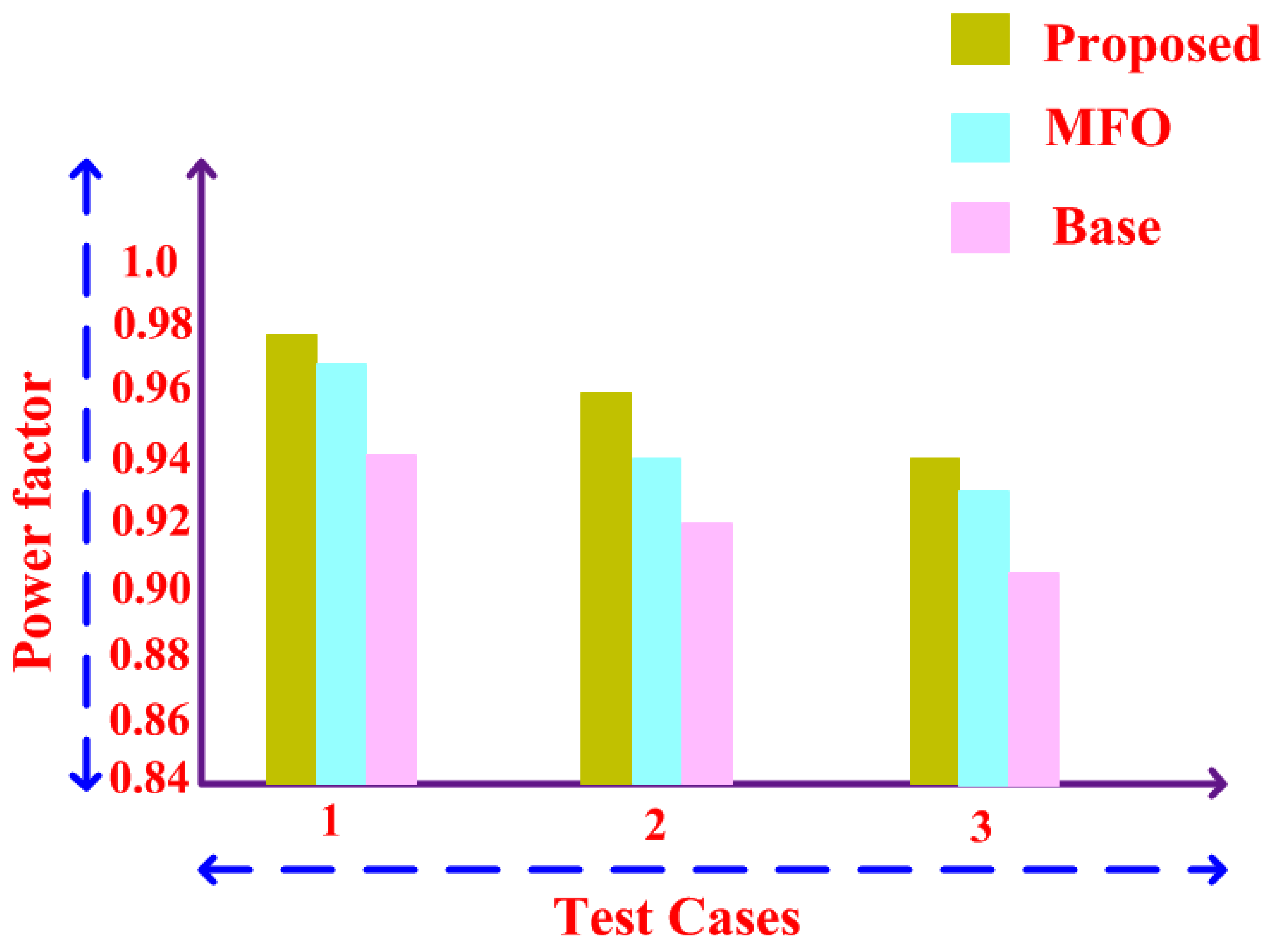
| Proposed | 0.9772 | 0.9675 | 0.9428 |
| MFO | 0.9542 | 0.9402 | 0.9156 |
| PI controller | 0.9435 | 0.9292 | 0.8921 |
© 2018 by the authors. Licensee MDPI, Basel, Switzerland. This article is an open access article distributed under the terms and conditions of the Creative Commons Attribution (CC BY) license (http://creativecommons.org/licenses/by/4.0/).
Share and Cite
Kamalapathi, K.; Priyadarshi, N.; Padmanaban, S.; Holm-Nielsen, J.B.; Azam, F.; Umayal, C.; Ramachandaramurthy, V.K. A Hybrid Moth-Flame Fuzzy Logic Controller Based Integrated Cuk Converter Fed Brushless DC Motor for Power Factor Correction. Electronics 2018, 7, 288. https://doi.org/10.3390/electronics7110288
Kamalapathi K, Priyadarshi N, Padmanaban S, Holm-Nielsen JB, Azam F, Umayal C, Ramachandaramurthy VK. A Hybrid Moth-Flame Fuzzy Logic Controller Based Integrated Cuk Converter Fed Brushless DC Motor for Power Factor Correction. Electronics. 2018; 7(11):288. https://doi.org/10.3390/electronics7110288
Chicago/Turabian StyleKamalapathi, Kuditi, Neeraj Priyadarshi, Sanjeevikumar Padmanaban, Jens Bo Holm-Nielsen, Farooque Azam, Chandrahasan Umayal, and Vigna K. Ramachandaramurthy. 2018. "A Hybrid Moth-Flame Fuzzy Logic Controller Based Integrated Cuk Converter Fed Brushless DC Motor for Power Factor Correction" Electronics 7, no. 11: 288. https://doi.org/10.3390/electronics7110288
APA StyleKamalapathi, K., Priyadarshi, N., Padmanaban, S., Holm-Nielsen, J. B., Azam, F., Umayal, C., & Ramachandaramurthy, V. K. (2018). A Hybrid Moth-Flame Fuzzy Logic Controller Based Integrated Cuk Converter Fed Brushless DC Motor for Power Factor Correction. Electronics, 7(11), 288. https://doi.org/10.3390/electronics7110288