Abstract
In the context of surgical navigation systems based on augmented reality (AR), the key challenge is to ensure the highest degree of realism in merging computer-generated elements with live views of the surgical scene. This paper presents an algorithm suited for wearable stereoscopic augmented reality video see-through systems for use in a clinical scenario. A video-based tracking solution is proposed that relies on stereo localization of three monochromatic markers rigidly constrained to the scene. A PnP-based optimization step is introduced to refine separately the pose of the two cameras. Video-based tracking methods using monochromatic markers are robust to non-controllable and/or inconsistent lighting conditions. The two-stage camera pose estimation algorithm provides sub-pixel registration accuracy. From a technological and an ergonomic standpoint, the proposed approach represents an effective solution to the implementation of wearable AR-based surgical navigation systems wherever rigid anatomies are involved.
1. Introduction
Augmented reality (AR) [1] is a ground-breaking technology in machine vision and computer graphics and may open the way for significant technological developments in the context of image-guided surgery (IGS). In AR-based applications, the key challenge is to ensure the highest degree of realism in merging computer-generated elements with live views of the surgical scene.
AR in IGS allows merging of real views of the patient with computer-generated elements generally consisting of patient-specific three-dimensional (3D) models of anatomy extracted from medical datasets (Figure 1). In this way, AR establishes a functional and ergonomic integration between surgical navigation and virtual planning by providing physicians with a virtual navigation aid contextually blended within the real surgical scenario [2].
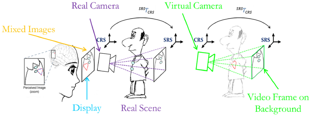
Figure 1.
Augmented Reality video see-through paradigm: the 2D virtual image (heart) is mixed into an image frame of the real world grabbed by the external camera.
In recent years, there has been a growing research interest in AR in medicine, which has driven a remarkable increase in the number of published papers. A PubMed search was performed of publications with the terms “augmented reality” OR “mixed reality” in the title or abstract. The first publication dated back to 1995 [3]. After 13 years, on 31 December 2008, the number of publications reached 255. During the last seven years, between 1 January 2009 and 30 April 2016, 647 papers were published, 168 of them in the past year. Nonetheless, only a few of the reported publications dealt with clinical validation of the technology described, and even fewer addressed its in vivo assessment. This is mostly due to the technological barriers encountered in the attempt to integrate similar AR systems into the surgical workflow.
Based on these considerations, the present work is aimed at developing strategies that could facilitate the profitable introduction of wearable AR systems to clinical practice.
In the realm of AR-based IGS systems, various display technologies have been proposed. In light of avoiding abrupt changes to the surgical setup and workflow, historically the first AR-based surgical navigation systems were implemented on the basis of commonly used devices [4] such as surgical microscopes [5,6]. In laparoscopy, and generally in endoscopic surgery, the part of the environment where the surgeon’s attention is focused during the surgical task (DVV’s Perception Location [7]) is a stand-up monitor. Indeed, in such procedures, the surgeon operates watching endoscopic video images reproduced on the spatial display unit [8,9]. Therefore, the virtual information is usually merged with real-time video frames grabbed by the endoscope and presented on a stand-up monitor [10,11,12].
Alternative and promising approaches based on integral imaging (II) technology have been proposed [13,14]. II displays use a set of 2D elemental images from different perspectives to generate a full-parallax 3D visualization. Therefore, with II-based displays, a proper 3D overlay between virtual content and a real scene can be obtained. Certain embodiments of this technology have been specifically designed and tested for maxillofacial surgery and neurosurgery [15,16,17,18,19]. The II paradigm can provide the user with an egocentric viewpoint and a full-parallax augmented view in a limited viewing zone (imposed by the II display). However, wearable embodiments of II technology still require further development of both hardware and software aspects [20].
In general, the quality of an augmented reality (AR) experience, particularly in IGS systems, depends on how well the virtual content is blended with the surgical scene spatially, photometrically, and temporally [21]. In this regard, wearable AR systems offer the most ergonomic solution in those medical tasks that are manually performed under the surgeon’s direct vision (open surgery, introduction of biopsy needle, palpation, etc.) because they minimize the extra mental effort required to switch focus between the real surgical task and the augmented view presented on the external display. Wearable AR systems based on head-mounted displays (HMDs) intrinsically provide the user with an egocentric viewpoint and do not limit freedom of movement around the patient [22,23,24]. Standard HMDs provide both binocular parallax and motion parallax and smoothly augment the user’s perception of the surgical scene throughout the specific surgical procedure. At present, they are less obtrusive in the operating room (OR) than II systems. In HMDs, the see-through capability is provided through either a video or an optical see-through paradigm.
Typically, in optical see-through HMD systems, the user’s direct view is augmented by the projection of virtual information either on semi-transparent displays placed in front of the eyes or directly onto the retina [25]. Accurate alignment between the direct view of the real scene and the virtual information is provided by real-time tracking of the visor and user-specific calibration that accounts for the change in relative position and orientation (pose) between display and eyes each time the user wears or moves the HMD [26,27]. Display-eye calibration is necessary to model intrinsically and extrinsically the virtual view frustum to the user’s real one [28].
The video see-through solution is instead based on external cameras rigidly fixed in front of the HMD. In these systems, although the field of view is limited by the size of the camera optics and displays, a user-specific calibration routine is not necessary. Furthermore, in video see-through systems, the real scene and the virtual information can be synchronized, whereas in optical see-through devices, there is an intrinsic lag between immediate perception of the real scene and inclusion of the virtual elements. Therefore, at the current technological level, the use of video see-through systems is immediate, at least for those IGS applications that can tolerate slight delays between capture of the real scene by the cameras and its final presentation in augmented form.
Accurate alignment between the real scene and the virtual content is provided by tracking the HMD in relation to the real world (represented by matrix in Figure 1), which is usually performed by means of an external tracker [29].
In a previous work, we presented an early system based on a commercially available HMD equipped with two external cameras aligned to the user’s eyes [23]. The see-through ability was created by combining 3D computer-generated models obtained by processing radiological images (e.g., CT or MRI) [30] with live views of the real patient. The distinctive feature of that AR system was that the pair of external cameras served both to capture the real scene and to perform stereo tracking.
As the authors, we share the conviction that the absence of an external tracker is a key element in enabling smooth and profitable integration of AR systems into the surgical workflow. Surgical navigation systems based on external infrared trackers have the major drawback of introducing unwanted line-of-sight constraints into the OR and of adding error-prone technical complexity to the surgical procedure [29]. Other tracking modalities are based on more complex surface-based tracking algorithms [12,31]. As an alternative to optical tracking, electromagnetic tracking systems are particularly suited for tracking hidden structures [32], but their accuracy and reliability are severely affected by the presence of ferromagnetic and/or conductive materials [33].
Standard video-based tracking methods featuring the use of large template-based markers provide highly accurate results in non-stereoscopic systems. Nonetheless, they are not suited for use in a surgical setting because they limit the surgeon’s line of sight given their planar structure and they may occlude the visibility of the operating field.
In that early system, and as previously done in [10,34], real-time registration of the virtual content to the real images was achieved by localizing chromatically distinguishable spherical markers. The video marker-based registration method registers the virtual 3D space to the camera coordinate system (CRS) through real-time determination of the camera pose in the radiological coordinate system (SRS).
Small spherical markers do not seriously affect the line of sight and can be conveniently placed on the patient’s skin with minimal logistic impact on the surgical workflow. With the objective of increasing system usability, the minimum set of markers (i.e., three) that could ensure a finite number of solutions to the camera pose estimation problem was chosen. The chromatic differences among the three markers and the stereo-camera setup enabled solution of the stereo correspondence problem and real-time computation of camera pose without the ambiguity of the general perspective-3-point (P3P) problem [35]. In practice, thanks to stereo tracking, the camera pose estimation problem can be reduced to determining the standard closed-form least-squares solution of the absolute orientation problem (AOP) given a set of three correspondences in the two 3D coordinate systems (CRS and SRS) [36]. The coordinates of the three markers in the CRS were recovered by applying stereo localization routines to the pairs of conjugate projections of the marker centroids taken from the image planes of the two cameras. Image coordinates of the marker centroids were determined by performing a feature extraction task using color segmentation and circular shape recognition. Hence, in the early system, robust feature extraction was crucial to providing accurate geometric registration.
Unfortunately, the shortcomings of the earlier approach were twofold: the non-fully controllable and/or inconsistent lighting conditions in the OR, and the intrinsic difficulty of robustly classifying three different colors using a standard thresholding technique. These shortcomings cannot be neglected if the system is to be integrated into the surgical workflow. Adoption of stringent thresholding criteria in the segmentation step may in fact result in inconsistent target identification because the connected regions tend to be poorly segmented. On the contrary, large thresholds may generate badly segmented regions or yield incorrect markers labelling.
In the present work, we shall present a tracking-by-detection solution that uses monochromatic markers and new marker labeling strategies to increase the robustness of the video-based tracking method under non-controllable lighting conditions.
In addition, the proposed solution overcomes another limitation of the earlier algorithm. As mentioned above, the 3D position of the markers in the CRS is estimated through stereoscopic triangulation routines applied to pairs of images acquired by the two external cameras. Nevertheless, the anthropomorphic geometry of the stereo setup can ensure adequate marker localization accuracy only at close distances. This localization error is inherent to the stereoscopic geometry and depends on the accuracy of the disparity estimate in the proposed feature extraction procedure and on the calibration errors in estimating the intrinsic and extrinsic camera parameters [37]. In Section 2.2.2, an example of such inaccuracy due to the anthropomorphic geometry of the stereo setup is reported. To cope with this limitation in this work we added a PnP-based optimization step, which refines the pose of both cameras separately and yields sub-pixel registration accuracy in the image plane.
Another interesting landmark-based mono-camera tracking solution has been proposed by Schneider et al. [38]. Their approach, based on an efficient and innovative 2D/3D point pattern matching algorithm, was specifically designed for computationally low-power devices and was proven to yield good results in terms of image registration accuracy and computational performance. Compared to that solution, our method needs fewer reference landmarks (i.e., three), whereas their single-view approach for estimating the camera pose cannot work if fewer than six landmarks can be seen. Use of a minimum set of three fiducial markers is in fact intended to limit the logistic payload for setup, and this aspect is key for facilitating the smooth integration of the system into the surgical workflow. The proposed solution tackles the ambiguity of the P3P problem through the stereoscopic settings of the video see-through system.
To the best of the authors’ knowledge, no previous work in AR has addressed the image-to-patient registration problem and has achieved sub-pixel registration accuracy through a video marker-based method that uses only three chromatically indistinguishable markers.
2. Materials and Methods
This section is organized as follows. Section 2.1 provides a detailed description of the hardware and of the software libraries used to implement the proposed stereoscopic AR mechanism. Section 2.2 describes the new methods used to solve marker labeling and to obtain a first estimate of the camera pose in relation to the SRS. The same subsection also describes the optimization method that solves the perspective-3-point (P3P) problem and yields sub-pixel registration accuracy in the image plane. Finally, Section 2.3 explains the methodology used to evaluate registration accuracy.
2.1. System Overview
The aim of this work is to present a robust and accurate video-based tracking method suited for use in a clinical scenario. The solution is based on tracking three indistinguishable markers. The algorithm was developed for a HMD AR system, but it could be applied to other stereoscopic devices like binocular endoscopes or binocular microscopes. Reference hardware has been chosen to achieve a low-cost system by assembling off-the-shelf components and manufacturing custom-made parts. The custom-made video see-through HMD was made from a Z800 3D visor (eMagin, Hopewell Junction, NY, USA) (Figure 2). The HMD is provided with dual OLED panels and features a diagonal field of view (FoV) of 40°.
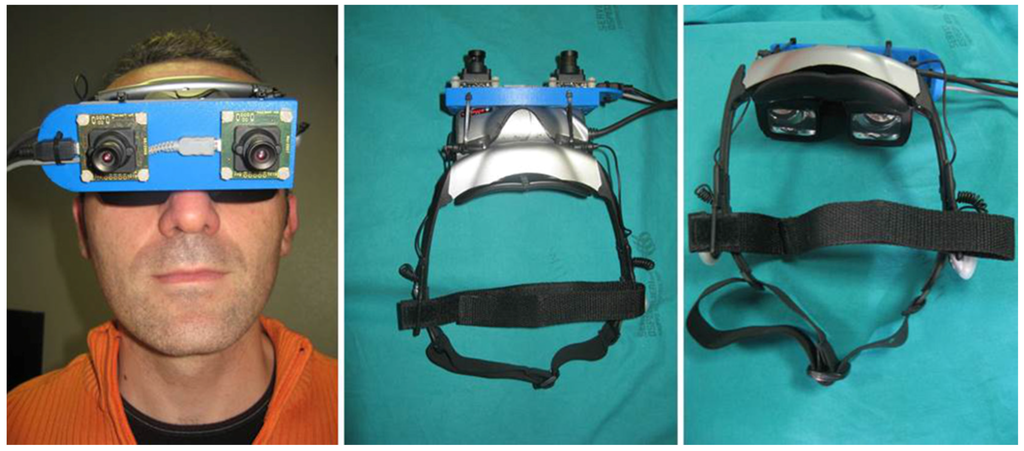
Figure 2.
Video see-through head-mounted display (HMD) obtained by mounting two external cameras on top of a commercial 3D visor.
A plastic frame (ABS) was built through rapid prototyping to act as a support for the two external USB cameras equipped with 1/3′′ image sensors UI-1646LE (IDS, Imaging Development Systems GmbH, Obersulm, Germany). By means of this support, the two cameras are mounted parallel to each other with an anthropometric interaxial distance () to provide a quasi-orthoscopic view of the augmented scene mediated by the visor. When the user looks at the real world while wearing the HMD, there are no appreciable differences between natural and visor-mediated views [39].
A toed-in camera configuration would be preferable for achieving better stereo overlap at close working distances, but if not coupled with simultaneous convergence of the optical display axes, this would go against the objective of this work: achievement of a quasi-orthostereoscopic AR HMD. As a matter of fact, another study by the authors has presented a different video see-through HMD that features the possibility of adjusting the degree of convergence of the stereo camera pair as a function of the working distance [40].
The Z800 HMD receives video frames from the computer via VGA cable and alternately transmits them to left and right internal monitors at 60 Hz in sync with the vsync signal. Therefore, the software, which renders and mixes the virtual model with the real frames, must set up and exchange left and the right views synchronously with the vsync signal as well. The proposed software application elaborates the grabbed video frames to perform real-time registration. Due to the computational complexity of the whole video see-through paradigm, a multithreaded application was implemented to distribute the operations among available processors to guarantee synchronization of the two views to be sent to the HMD. One thread sets up the AR views and ensures their synchronization, whereas the other performs video-based tracking.
A synthetic functional and logical description of the AR mechanism is as follows: real cameras grab video frames of the scene; video frames, after radial distortion compensation, are screened as backgrounds of the corresponding visor display; virtual anatomies, reconstructed offline from radiological images, are coherently merged to create the augmented scene. For coherent merging of real scenes and virtual content, the virtual content is observed by a couple of virtual viewpoints (virtual cameras) with projective parameters that mimic those of the real cameras and with poses that vary according to the real-time marker-based tracking method (Figure 3).
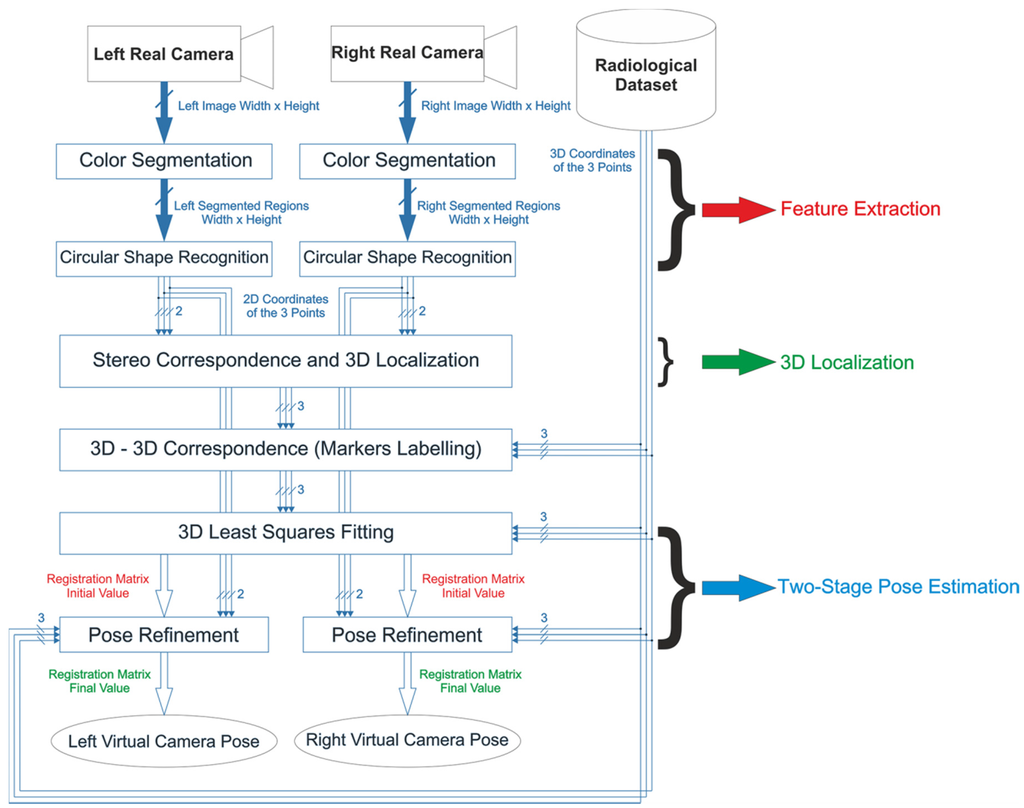
Figure 3.
Localization and registration algorithm.
This AR mechanism was implemented in software libraries built in C++ on top of the multipurpose EndoCAS Navigator Platform modules [41]. Management of the virtual 3D scene was carried out through the OpenSG 1.8 open-source software framework (www.opensg.org). As for the machine vision routines needed to implement the video-based tracking method, the Halcon 7.1 library (MVTec Software Gmbh, Munich, Germany, 2008) was used. The whole application was implemented to be compatible with several 3D displays (working either with side-by-side or alternate frames) and with all cameras for which DirectShow drivers by Microsoft are available. The configurable software framework is described in more detail in [42].
In a video see-through system, to achieve an accurate and robust fusion between reality and virtuality, the virtual scene must be rendered so that the following three conditions are satisfied:
- The virtual camera projection models ≈ to the real ones.
- The relative pose between the two virtual cameras of the stereo setup ≈ to the real one.
- The pose of the virtual anatomies/surgical tools ≈ to the real ones.
The first condition implies that the virtual camera viewing frustums are to be modeled on the real ones in terms of image size, focus length, and center of projection (intrinsic calibration). At the same time, the second condition implies that the relative pose between the two virtual cameras of the stereo setup must be set equal to the pose between the two real cameras (extrinsic calibration).
These two calibration routines can be performed offline by implementing Zhang’s calibration routine [43] (in this research, Halcon libraries were used for this task). The nonlinear part of the internal camera model (due to lens radial distortion) was taken into account by compensating for the distortion over the grabbed images before rendering them onto the background of the left and right visor displays.
Finally, the pose of the virtual elements in the virtual scene must be set equal to the real pose between the real anatomies/tools and the physical camera. This latest condition was satisfied by using a video marker-based tracking method that will be described in the following subsections.
2.2. 3D Localization and Tracking Algorithm
The poses of the two cameras relative to the anatomy and vice versa are determined by tracking passive colored markers constrained to the surgical scene in defined positions. The proposed video-based tracking solution relies on stereo localization of three monochromatic markers and is robust to inconsistent lighting conditions. 3D coordinates of the markers in the left CRS are retrieved by applying stereo 3D Localization routines on pairs of conjugate projections of the markers’ centroids onto the image planes of the two cameras. Image coordinates of the marker centroids are determined by a feature extraction task performed using Color Segmentation and Circular Shape Recognition.
2.2.1. Feature Extraction, Stereo Correspondence, and Marker Labeling
As an overall concept, color segmentation based on thresholding must ensure a robust tradeoff between illumination invariance and absence of segmentation overlaps among differently colored regions. Adoption of stringent thresholding criteria may result in inconsistent target identification because the connected regions may be poorly segmented. On the contrary, large thresholds may generate badly segmented regions or yield incorrect marker labeling in the case of multicolored markers. This drawback is emphasized by the use of cheap and/or small cameras equipped with Bayer filter color sensors. Such sensors provide inferior color quality and lower signal-to-noise ratio than those based on three sensors and a trichroic beam splitter prism for each pixel (3-CCD sensing). Use of monochromatic markers makes it possible to achieve higher robustness in the Feature Extraction step and in the presence of non-controllable and inconsistent lighting conditions because incorrect labelling is intrinsically avoided.
To cope partially with the limitation of using visible light as an information source, Color Segmentation was performed in the HSV (hue, saturation, value) color space. HSV is a human-oriented representation of the distribution of the electromagnetic radiation energy spectrum [44]. HSV enables a sufficiently robust segmentation of objects that undergo non-uniform levels of illumination intensity, shadows, and shading [45,46]. The assumption is that light intensity primarily affects the value (V) channel, whereas the hue (H), and to a lesser extent the saturation (S) channels are less influenced by illumination changes [46]. The chromatic choice for the markers must lean towards highly saturated colors, as was done in [47]. In this way, segmentation based on thresholding becomes more selective: it can be performed with a high cutoff value in the S-channel.
After Color Segmentation, three broader connected regions with a circular shape factor >0.5 are identified on both images. Then, the centroids of the selected regions are determined. These image points correspond to the projections of the marker centroids on the image planes of the two cameras. Figure 4 shows the results of Color Segmentation. After Circular Shape Recognition, the 2D projections of the three marker centroids on the left and right images are known.
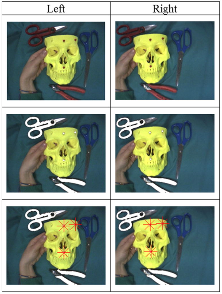
Figure 4.
Results of the Color Segmentation and Circular Shape Recognition steps. In the first row, left and right camera native frames are shown. The second row shows the results of Color Segmentation, and the third row shows the results of Circular Shape Recognition.
The Stereo Correspondence problem is solved with a method based on minimizing an energy term computed by applying standard projective rules to all possible permutations of matches between the feature-point triplets on the image pair. In more detail, knowing the internal parameters and the relative pose between the two cameras, it is possible to determine the 3D position of a point from its projections on the left and right cameras (stereo triangulation). The 3D position of the point in the CRS can be approximated as the middle of the shortest segment joining the two projection lines. The distance between the two projection lines (DPL) is correlated with the localization error and depends on working distance, inter-camera distance, calibration quality, and identification accuracy of the conjugate image points. By working with a set of indistinguishable markers, it is not possible to localize the markers in the CRS without ambiguity because the correspondence between projected points on the left and right cameras (known as conjugate points) is unknown. The algorithm calculates the position of the three marker centroids together with the associated DPL for each of the six possible permutations of possible conjugate point matches. Hence, the solution for the stereo correspondence problem is assumed to be the one that minimizes the sum of the three DPLs over the six permutations. Once the right correspondence has been determined, the positions of the three marker centroids in the CRS are given, and the Stereo Correspondence and 3D Localization steps are complete.
Figure 5 shows the results of the Stereo Correspondence step on a pair of sample images. Note that after this step, the correspondence between each of the projected marker centroids on the two images is known, but the marker labels (i.e., the 3D-3D Correspondence) remain unknown.
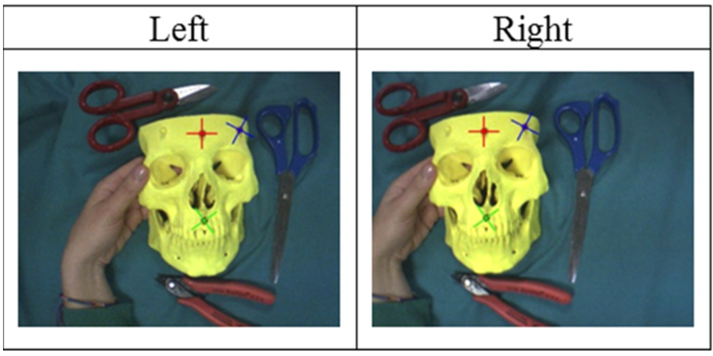
Figure 5.
Stereo Correspondence: The correspondence between the three points on the left and right images is solved using multiple stereoscopic triangulation routines on the six possible permutations of the three points. In the images, the correct correspondences between the three points are shown.
Therefore, before solving the registration problem, the 3D-3D Correspondence problem must be determined, which involves finding the proper set of corresponding points in the CRS and SRS. The 3D-3D Correspondence between the two sets of 3D points is solved by a geometric procedure that takes account of the similarity of the triangles formed by such points. This approach requires that the distances between markers not be equal.
2.2.2. Two-Stage Pose Estimation
The rigid transformation between the two reference systems, namely the camera pose and the SRS, is encapsulated by matrix . Pose estimation is performed using a two-stage method, with the first step being solving the AOP by standard 3D Least-Squares Fitting of the two point sets through SVD [36]. Figure 6 shows the visual results of the first registration step between the two reference systems. As shown in the figure, due to stereo localization inaccuracies, the image registration resulting from the AOP solution may be inaccurate.
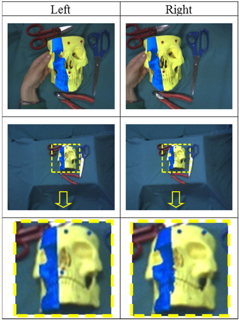
Figure 6.
Geometric registration through SVD: Geometric registration solved by a Least-Squares Fitting method that provides a first rough alignment between the virtual information and the real scene. As shown in the first row, at close distances (about 40 cm), geometric registration is sufficiently accurate in the presence of calibrated cameras and with reliable disparity estimates. As shown in the second row, far from the scene (~100 cm), alignment accuracy rapidly degrades. The third row shows a zoomed detail of the second row.
Because of the geometry of the stereo setup, the limited focal length, and the degradation of the stereo camera calibration, adequate accuracy of 3D Localization of the markers at greater distances cannot be ensured. The major error component in 3D Localization is along the optical axis (z-axis) and increases with the square of the distance. The depth resolution is calculated as in [37,48]:
As an example, let us assume that we have determined a fixed and ideally error-free estimate of the focal length and the baseline (in the described system, , ). Given a disparity accuracy of and a sensor diagonal of 1/3’’ (), the depth resolution is approximately at a working distance of 50 cm. At this error increases to approximately (see the last row of Figure 6). Therefore, because of data noise and the geometry of the stereo setup, the SVD solution of the AOP cannot yield a sufficiently accurate result in terms of geometric registration. On this basis, this paper proposes a methodology for refining the estimates of both camera poses to increase the accuracy of the video-based tracking technique.
The general problem of determining the pose of a calibrated camera with respect to a scene or object given its intrinsic parameters and a set of n world-to-image point correspondences was first formally introduced in the computer vision community by Fishler and Bolles in 1981 [49] using the term “Perspective-n-Point” problem (PnP). The PnP problem pertains to several areas of interest and is key to many fields like computer vision, robotics, and photogrammetry. In the transformation-based definition given in [49], the PnP problem aims to estimate the camera pose given a set of correspondences between n 3D points (known as “control points”) and their 2D projections in the image plane [50]. If the number of corresponding points is <six, which is the most common and practical situation, the PnP problem generally does not guarantee the uniqueness of the solution. The P3P problem entails the smallest subset of control points that yields a finite number of solutions. In computer-vision applications, study of the multi-solution phenomenon for the closed-form methods has become very popular because of the “pivotal role played” by the P3P problem within the set of problems with a large number of uncertainties [51].
Regardless of the number of control points, the PnP problem can be faced with mainly two categories of methods: closed-form methods and iterative optimization methods [52]. Closed-form methods are usually faster, but often do not provide a unique solution and are usually less accurate and more susceptible to noise [35,53,54,55,56,57]. Iterative optimization approaches are based on minimizing a chosen cost function and, if a good initial guess of the solution is provided, determine the closest solution [58,59]. In our case, the initial guess is provided by the SVD solution of the AOP. Therefore, we added a PnP-based iterative optimization step (with n = 3) to the pose estimation routine. The optimization problem can be formalized as:
where the residual function represents the absolute distance, on the image plane, between the measured projections after compensation of the radial distortion, and the calculated projections ; are computed by applying the transformation matrix and the projection matrix to the control points ; and is the unknown transformation matrix with six dof (three rotational and three translational). Hence, knowing , all the , and , can be calculated by minimizing the sum of the squared residuals. This optimization problem is solved using a library routine by Halcon. The iterative routine is applied to both left and right camera frames and provides more accurate image registration for the left and right views. Figure 7 shows the results of the Pose Refinement step applied over the images in the last row of Figure 6.
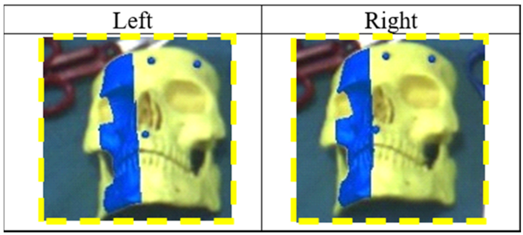
Figure 7.
Pose Refinement: Virtual information was perfectly aligned also at greater distances (approximately 100 cm) after the Pose Refinement step. The frames shown on the figures constitute a refinement of the augmented frames in the last row of Figure 6.
2.3. Evaluation of Registration Accuracy
Two experiments were performed to assess registration accuracy. The first aimed to evaluate the 2D visualization alignment between virtual and real information, as done in [60]. The goal of the second experiment was to estimate the error committed by the user in a target-reaching task, and hence a testing strategy similar to that proposed in [17] was used. For each trial, the errors on both channels (right and left) before and after the Pose Refinement step were measured.
The experimental setup consisted of a plastic board with dimensions (160 × 100 mm) intended to reproduce the area of a typical surgical field of intervention; this panel, covered by a layer of white cardboard, included reference holes close to the vertices in known positions. For this specific test, three red plastic spheres with a diameter of 5.92 mm (measured by a digital caliper with a resolution of 0.01 mm) were used as markers. The colored markers were arranged on top of the reference holes on the panel. The 3D coordinates of the marker centroids in the board reference system (i.e., SRS) were known.
The first experiment calculated the 2D target visualization error (TVE2D) expressed in pixels. The TVE2D represents the mean offset between real objects and their virtual reproductions on the image plane.
To this end, ten validation points in the form of black crosses were printed over the white cardboard in known positions. To assess the accuracy of the AR registration, the HMD was placed at four different positions with different distances and orientations in relation to the SRS (distances ranging between 300 and 900 mm).
For each AR view, TVE2D was measured between the centroids of the black crosses (real objects) and of the red crosses (virtual objects), as shown in Figure 8.
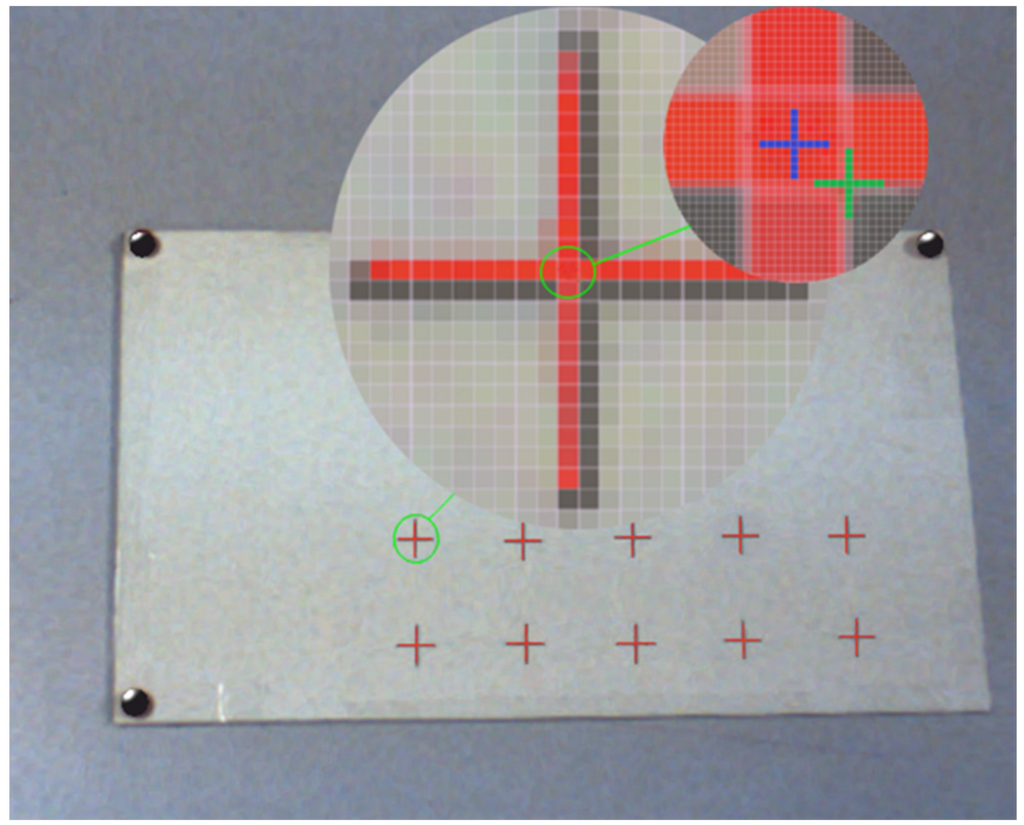
Figure 8.
Evaluation of the TVE: image frame from the left display at a distance of 300 mm between the HMD and the validation board. The two circles show a zoomed detail of the frame with the centroids of the virtual (red) and real (black) cross highlighted respectively in blue and green. The black virtual spheres align exactly with the real red markers.
The second experiment was aimed at empirically estimating the error committed by the user in the task of reaching a planned target point over a planar surface under AR guidance; this error was called the 3D target reaching error (TReachE3D). The user, under AR guidance, was asked to mark, using a thin pen over the white cardboard, the center of the virtual crosses showed on the displays. The test was repeated at four distances between 300 and 900 mm. After each test, the cardboard was scanned using a desktop scanner. Reached points were visually determined and expressed in the SRS (knowing the reference hole positions in the scanned image). Finally, the distances between reached and correct/planned points were computed.
3. Results
Table 1 presents the results of the first validation experiment for the left and right cameras before and after the Pose Refinement step. Errors were measured on the image plane and are expressed in pixels.

Table 1.
Mean and standard deviation of TVE2D over 10 validation points for both sides before and after Pose Refinement.
Knowing the intrinsic parameters of the two cameras, it is also possible to estimate the visualization error in space in mm (TVE3D) at fixed distances [10,60]. TVE3D is calculated by inverting the projection equation:
where is the estimated working distance, represents the focal length estimated in the calibration phase and corresponding to 4.8 mm, and is the scaling factor of the image sensor (number of pixels per unit of length). In the present case, can be calculated from the image sensor specifications and corresponds approximately to . The mean TVE3D at 700 mm for the left camera was 1.8 mm without Pose Refinement and was decreased to 0.9 mm by minimizing the reprojection error in the Pose Refinement step.
Figure 9 shows the results of the second experiment, which provided an estimate of spatial accuracy in 3D space. The Pose Refinement step increased the accuracy. Mean (µ) errors ± standard deviations (σ) at 700 mm for the left camera were 2.30 ± 0.91 and 1.00 ± 0.56 mm respectively before and after the Pose Refinement step. It is interesting to highlight the tendency of the error, without Pose Refinement, to drift upward approximately with the square of the distance between camera and validation board, following the same trend as the localization error. Finally, the computational payload for the entire algorithm was also evaluated. Depending on the scene and the environmental lighting, the average running time ranged between 10 and 15 ms. Running time was evaluated using a standard PC with a quad-core i7-3770@3.4GHz processor and 8GB RAM. The graphics card used was a GeForce GT 620 (NVIDIA, Santa Clara, CA, USA). In any case, the time required for the localization and registration thread was less than 33 ms (working at 60 Hz).
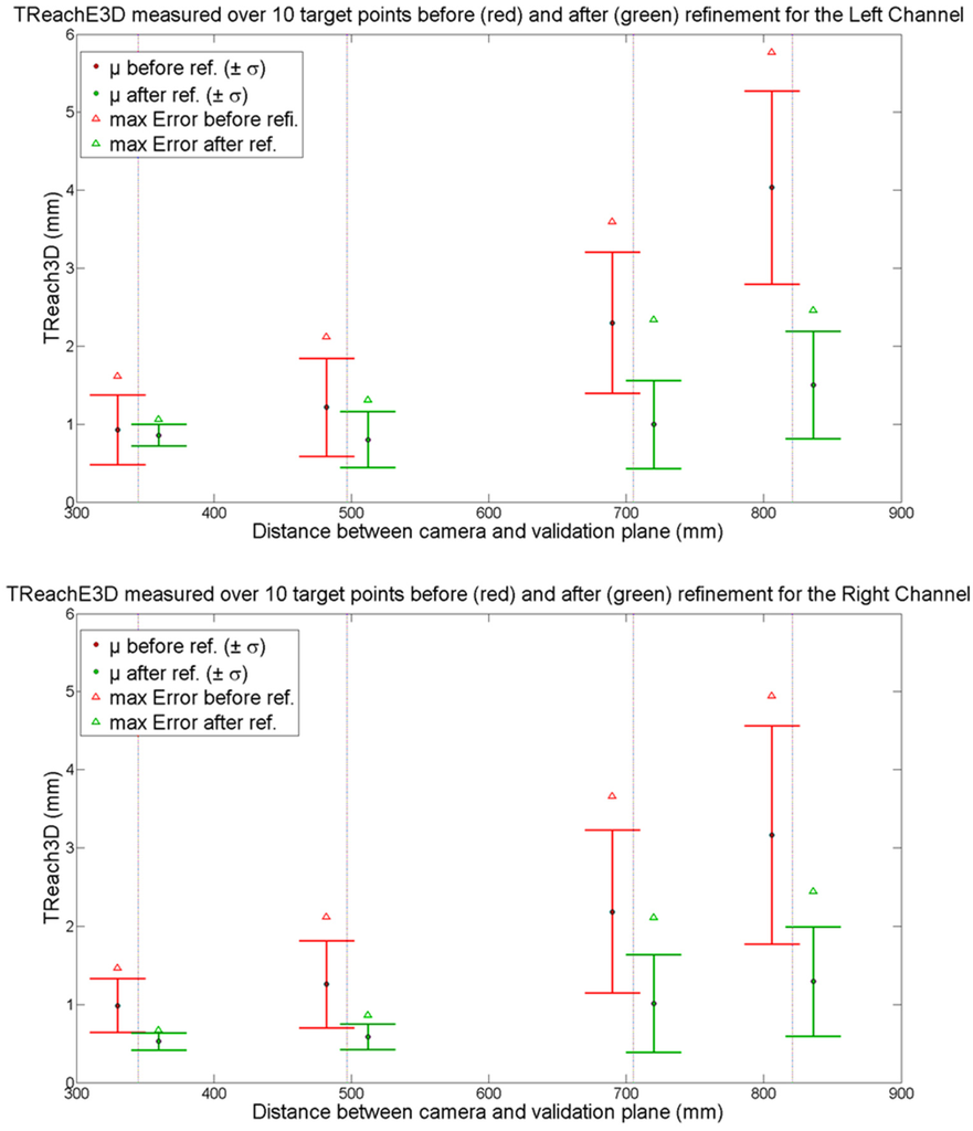
Figure 9.
Target reaching error in space (TReach3D) made by the user in the task of reaching target crosses on a board positioned at different distances under AR guidance. Red and green values, referring respectively to TReach3D before and after the Pose Refinement step, are slightly shifted along the x-axis for readability reasons.
4. Discussion and Conclusions
This paper has introduced new video-based tracking methods suitable for stereoscopic AR video see-through systems. The proposed solution is aimed at providing accurate camera pose estimation and is based on tracking three indistinguishable markers. The algorithm was developed for a wearable AR system, but it might also be applied to other stereoscopic devices like binocular endoscopes or binocular microscopes.
The proposed algorithm avoids the need for an external tracker to detect the relative pose between the cameras and the real scene. Coherent superimposition of virtual information onto real images is achieved through a video marker-based tracking method.
Video-based tracking methods need a robust estimation of the physical camera projective model, i.e., intrinsic and extrinsic camera parameters. In the proposed AR application, the estimate of the intrinsic camera parameters is the result of a standard off-line calibration process, whereas the extrinsic camera parameters are determined online. Solutions for simultaneous on-line estimation of both intrinsic and extrinsic camera parameters have been proposed [61]. In any case, the limitation of using fixed intrinsic parameters does not generally affect the overall usability of wearable video see-through AR systems. Camera zooming, which implies a change in intrinsic camera parameters, would in fact cause an unnatural sensation to the user because of the resulting incoherence between changes in motion perceived by the user in the displayed images (due to changes in camera field of view) and actual head motions. The proposed solution takes into account considerations of system applicability in a clinical scenario.
Colored spheres were chosen as markers. The reason for this choice was that small spherical markers can be conveniently placed around the surgical area without compromising the surgeon’s field of view. The use of a minimum set of three fiducial markers is also intended to limit the logistic payload for setup.
Use of monochromatic markers makes it possible to achieve high robustness in the feature extraction step and also in the presence of non-controllable and/or inconsistent lighting conditions. This choice has required marker labeling methods. The proposed algorithm solves both stereo and 3D–3D correspondence problems before registration. The stereo correspondence problem is solved by applying multiple stereoscopic triangulation routines on pairs of images simultaneously grabbed from the two cameras. 3D–3D correspondence is determined by a geometrical procedure.
Furthermore, the proposed algorithm provides sub-pixel registration accuracy between real and virtual scenes thanks to a PnP-based optimization step. The strategy for refining each camera pose does not need a perfectly calibrated stereoscopic system.
A key factor in performing highly accurate measurements with stereoscopic systems is to know with extreme confidence the relative pose between the two cameras. A relevant drawback of using wearable trackers is represented by the non-ideal stability in the constraints between the two stereo cameras, which may cause a potential change in their relative pose while the visor is being used [40]. Such systems need frequent calibration to cope with degradation of the stereo calibration over time.
Pose refinement provides sub-pixel video registration accuracy and can compensate for potential loss of accuracy in the estimate of the relative pose between the two cameras. The accuracy and robustness of the proposed wearable AR stereoscopic video see-through display pave the way for the introduction of such technology in clinical practice.
One way to translate this solution into clinical practice and to provide radiological images for patient registration is the following: virtual anatomies are reconstructed offline from radiological images [30]; the positions of the three fiducial points are identified on the 3D model of the anatomy (e.g., by applying radiopaque markers on the patient before acquiring a CT image, or by considering physical landmarks as references); before the surgical procedure, three monochromatic markers, whose centroids must be in the same position as the three fiducial points, are anchored onto the patient. This approach is well known and used in other IGS systems.
The proposed solution has already been used in a study in maxillofacial surgery that was published in 2014 [62]. The study was focused on in vitro validation of the proposed stereoscopic video see-through AR system as an aid for manual repositioning of facial bone fragments. The AR visualization modality used in the clinical study, which provides an ergonomic interaction paradigm within the augmented scene, draws its inspiration from and tries to mimic physically the paradigm on which the PnP problem is formulated. This task-oriented AR visualization modality has been more thoroughly described in a recently published manuscript [63].
More recently, the video-based tracking method has been positively validated in vitro to aid trocar insertion during a percutaneous procedure in orthopedic surgery [64].
Supplementary Materials
The following are available online at www.mdpi.com/2079-9292/5/3/59/s1. Video S1: Video_Demo_Maxillofacial_Application.
Acknowledgments
This work was funded by the Italian Ministry of Health grant, SThARS (Surgical training in identification and isolation of deformable tubular structures with hybrid Augmented Reality Simulation, 6/11 2014–5/11/2017), Grant “Ricerca finalizzata e Giovani Ricercatori 2011–2012”, Young Researchers, Italian Ministry of Health.
Author Contributions
F.C. and V.F. designed and developed the wearable AR system and proposed the localizer-free video-based tracking mechanism. F.C., S.M., and C.F. implemented the AR software framework. M.F., P.D.P., and F.C. set the requirements for the new wearable solution for AR-based image-guided surgery. The main goal of this analysis was to insert the proposed system within the context of state-of-the-art solutions for AR-based image-guided surgery. F.C. and V.F. analyzed and discussed the results.
Conflicts of Interest
The authors declare no conflict of interest.
References
- Milgram, P.; Kishino, F. A taxonomy of mixed reality visual-displays. IEICE Trans. Inf. Syst. 1994, E77-D (12), 1321–1329. [Google Scholar]
- Kersten-Oertel, M.; Jannin, P.; Collins, D.L. The state of the art of visualization in mixed reality image guided surgery. Comput. Med. Imaging Graph. 2013, 37, 98–112. [Google Scholar] [CrossRef] [PubMed]
- Cuchet, E.; Knoplioch, J.; Dormont, D.; Marsault, C. Registration in neurosurgery and neuroradiotherapy applications. J. Image Guid. Surg. 1995, 1, 198–207. [Google Scholar] [CrossRef]
- Roberts, D.W.; Strohbehn, J.W.; Hatch, J.F.; Murray, W.; Kettenberger, H. A frameless stereotaxic integration of computerized tomographic imaging and the operating microscope. J. Neurosurg. 1986, 65, 545–549. [Google Scholar] [CrossRef] [PubMed]
- Edwards, P.J.; Hawkes, D.J.; Hill, D.L.G.; Jewell, D.; Spink, R.; Strong, A.; Gleeson, M. Augmentation of reality using an operating microscope for otolaryngology and neurosurgical guidance. J. Image Guid. Surg. 1995, 1, 172–178. [Google Scholar] [CrossRef]
- Edwards, P.J.; Hill, D.L.G.; Hawkes, D.J.; Spink, R.; Colchester, A.C.F.; Strong, A.; Gleeson, M. Neurosurgical guidance using the stereo microscope. In Computer Vision, Virtual Reality Robotics in Medicine; Ayache, N., Ed.; Springer: Berlin/Heidelberg, Germany, 1995; Volume 905, pp. 555–564. [Google Scholar]
- Kersten-Oertel, M.; Jannin, P.; Collins, D.L. Dvv: Towards a taxonomy for mixed reality visualization in image guided surgery. Med. Imaging Augment. Real. 2010, 6326, 334–343. [Google Scholar]
- Freysinger, W.; Gunkel, A.R.; Thumfart, W.F. Image-guided endoscopic ENT surgery. Eur. Arch. Oto-Rhino-Laryngol. 1997, 254, 343–346. [Google Scholar] [CrossRef]
- Caversaccio, M.; Giraldez, J.G.; Thoranaghatte, R.; Zheng, G.; Eggli, P.; Nolte, L.P.; Ballester, M.A.G. Augmented reality endoscopic system (ARES): Preliminary results. Rhinology 2008, 46, 156–158. [Google Scholar] [PubMed]
- Baumhauer, M.; Simpfendorfer, T.; Muller-Stich, B.P.; Teber, D.; Gutt, C.N.; Rassweiler, J.; Meinzer, H.P.; Wolf, I. Soft tissue navigation for laparoscopic partial nephrectomy. Int. J. Comput. Assist. Radiol. Surg. 2008, 3, 307–314. [Google Scholar] [CrossRef]
- Ieiri, S.; Uemura, M.; Konishi, K.; Souzaki, R.; Nagao, Y.; Tsutsumi, N.; Akahoshi, T.; Ohuchida, K.; Ohdaira, T.; Tomikawa, M.; et al. Augmented reality navigation system for laparoscopic splenectomy in children based on preoperative ct image using optical tracking device. Pediatr. Surg. Int. 2012, 28, 341–346. [Google Scholar] [CrossRef] [PubMed]
- Haouchine, N.; Dequidt, J.; Berger, M.O.; Cotin, S. Deformation-based augmented reality for hepatic surgery. Stud. Health Technol. Inf. 2013, 184, 182–188. [Google Scholar]
- Liao, H.; Nakajima, S.; Iwahara, M.; Kobayashi, E.; Sakuma, I.; Yahagi, N.; Dohi, T. Intra-operative real-time 3-D information display system based on integral videography. In Proceedings of the 4th International Conference on Medical Image Computing and Computer-Assisted Intervention—Miccai 2001, Utrecht, The Netherlands, 14–17 October 2001; Niessen, W., Viergever, M., Eds.; Springer: Berlin/Heidelberg, Germany, 2001; Volume 2208, pp. 392–400. [Google Scholar]
- Liao, H.; Hata, N.; Nakajima, S.; Iwahara, M.; Sakuma, I.; Dohi, T. Surgical navigation by autostereoscopic image overlay of integral videography. IEEE Trans. Inf. Technol. Biomed. 2004, 8, 114–121. [Google Scholar] [CrossRef] [PubMed]
- Iseki, H.; Masutani, Y.; Iwahara, M.; Tanikawa, T.; Muragaki, Y.; Taira, T.; Dohi, T.; Takakura, K. Volumegraph (overlaid three-dimensional image-guided navigation). Clinical application of augmented reality in neurosurgery. Stereotact. Funct. Neurosurg. 1997, 68, 18–24. [Google Scholar] [CrossRef] [PubMed]
- Narita, Y.; Tsukagoshi, S.; Suzuki, M.; Miyakita, Y.; Ohno, M.; Arita, H.; Saito, Y.; Kokojima, Y.; Watanabe, N.; Moriyama, N.; et al. Usefulness of a glass-free medical three-dimensional autostereoscopic display in neurosurgery. Int. J. Comput. Assist. Radiol. Surg. 2014, 9, 905–911. [Google Scholar] [CrossRef] [PubMed]
- Liao, H.; Inomata, T.; Sakuma, I.; Dohi, T. Surgical navigation of integral videography image overlay for open MRI-guided glioma surgery. Med. Imaging Augment. Real. 2006, 4091, 187–194. [Google Scholar]
- Liao, H.E.; Inomata, T.; Sakuma, I.; Dohi, T. 3-D augmented reality for mri-guided surgery using integral videography autostereoscopic image overlay. IEEE Trans. Biomed. Eng. 2010, 57, 1476–1486. [Google Scholar] [CrossRef] [PubMed]
- Suenaga, H.; Tran, H.H.; Liao, H.G.; Masamune, K.; Dohi, T.; Hoshi, K.; Mori, Y.; Takato, T. Real-time in situ three-dimensional integral videography and surgical navigation using augmented reality: A pilot study. Int. J. Oral Sci. 2013, 5, 98–102. [Google Scholar] [CrossRef] [PubMed]
- Ferrari, V.C.E. Wearable augmented reality light field optical see-through display to avoid user dependent calibrations: A feasibility study. In Proceedings of the IEEE Science and Information Conference, SAI 2016, London, UK, 13–15 July 2016; pp. 1211–1216.
- Sielhorst, T.; Feuerstein, M.; Navab, N. Advanced medical displays: A literature review of augmented reality. J. Disp. Technol. 2008, 4, 451–467. [Google Scholar] [CrossRef]
- Birkfellner, W.; Figl, M.; Huber, K.; Watzinger, F.; Wanschitz, F.; Hummel, J.; Hanel, R.; Greimel, W.; Homolka, P.; Ewers, R.; et al. A head-mounted operating binocular for augmented reality visualization in medicine-design and initial evaluation. IEEE Trans. Med. Imaging 2002, 21, 991–997. [Google Scholar] [CrossRef] [PubMed]
- Ferrari, V.; Megali, G.; Troia, E.; Pietrabissa, A.; Mosca, F. A 3-D mixed-reality system for stereoscopic visualization of medical dataset. IEEE Trans. Biomed. Eng. 2009, 56, 2627–2633. [Google Scholar] [CrossRef] [PubMed]
- Sielhorst, T.; Bichlmeier, C.; Heining, S.M.; Navab, N. Depth perception—A major issue in medical AR: Evaluation study by twenty surgeons. In Proceedings of the 9th International Conference on Medical Image Computing and Computer-Assisted Intervention—MICCAI 2006, Copenhagen, Denmark, 1–6 October 2006; Volume 4190, pp. 364–372.
- Rolland, J.P.; Fuchs, H. Optical versus video see-through mead-mounted displays in medical visualization. Presence Teleoperators Virtual Environ. 2000, 9, 287–309. [Google Scholar] [CrossRef]
- Kellner, F.; Bolte, B.; Bruder, G.; Rautenberg, U.; Steinicke, F.; Lappe, M.; Koch, R. Geometric calibration of head-mounted displays and its effects on distance estimation. IEEE Trans. Vis. Comput. Graph. 2012, 18, 589–596. [Google Scholar] [CrossRef] [PubMed]
- Genc, Y.; Tuceryan, M.; Navab, N. Practical solutions for calibration of optical see-through devices. Int. Symp. Mixed Augment. Real. Proc. 2002, 169–175. [Google Scholar]
- Plopski, A.; Itoh, Y.; Nitschke, C.; Kiyokawa, K.; Klinker, G.; Takemura, H. Corneal-imaging calibration for optical see-through head-mounted displays. IEEE Trans. Vis. Comput. Graph. 2015, 21, 481–490. [Google Scholar] [CrossRef] [PubMed]
- Navab, N.; Heining, S.M.; Traub, J. Camera augmented mobile C-arm (CAMC): Calibration, accuracy study, and clinical applications. IEEE Trans. Med. Imaging 2010, 29, 1412–1423. [Google Scholar] [CrossRef] [PubMed]
- Ferrari, V.; Carbone, M.; Cappelli, C.; Boni, L.; Melfi, F.; Ferrari, M.; Mosca, F.; Pietrabissa, A. Value of multidetector computed tomography image segmentation for preoperative planning in general surgery. Surg. Endosc. 2012, 26, 616–626. [Google Scholar] [CrossRef] [PubMed]
- Marmulla, R.; Hoppe, H.; Muhling, J.; Eggers, G. An augmented reality system for image-guided surgery. Int. J. Oral Maxillofac. Surg. 2005, 34, 594–596. [Google Scholar] [CrossRef] [PubMed]
- Ferrari, V.; Viglialoro, R.M.; Nicoli, P.; Cutolo, F.; Condino, S.; Carbone, M.; Siesto, M.; Ferrari, M. Augmented reality visualization of deformable tubular structures for surgical simulation. Int. J. Med. Robot. 2015, 12, 231–240. [Google Scholar] [CrossRef] [PubMed]
- Franz, A.M.; Haidegger, T.; Birkfellner, W.; Cleary, K.; Peters, T.M.; Maier-Hein, L. Electromagnetic tracking in medicine—A review of technology, validation, and applications. IEEE Trans. Med. Imaging 2014, 33, 1702–1725. [Google Scholar] [CrossRef] [PubMed]
- Kanbara, M.; Okuma, T.; Takemura, H.; Yokoya, N. A stereoscopic video see-through augmented reality system based real-time vision-based registration. In Proceedings of the IEEE Virtual Reality Conference, New Brunswick, NJ, USA, 18–22 March 2000; pp. 255–262.
- Haralick, R.M.; Lee, C.N.; Ottenberg, K.; Nolle, M. Review and analysis of solutions of the 3-point perspective pose estimation problem. Int. J. Comput. Vis. 1994, 13, 331–356. [Google Scholar] [CrossRef]
- Arun, K.S.; Huang, T.S.; Blostein, S.D. Least-squares fitting of 2 3-D point sets. IEEE Trans. Pattern Anal. Mach. Intell. 1987, 9, 699–700. [Google Scholar] [CrossRef]
- Kyto, M.; Nuutinen, M.; Oittinen, P. Method for measuring stereo camera depth accuracy based on stereoscopic vision. Three-Dimens. Imaging Interact. Meas. 2011, 7864. [Google Scholar] [CrossRef]
- Schneider, A.; Baumberger, C.; Griessen, M.; Pezold, S.; Beinemann, J.; Jurgens, P.; Cattin, P.C. Landmark-based surgical navigation. Clin. Image-Based Proc. Transl. Res. Med. Imaging 2014, 8361, 57–64. [Google Scholar]
- Cutolo, F.; Parchi, P.D.; Ferrari, V. Video see through ar head-mounted display for medical procedures. In Proceedings of the 17th IEEE International Symposium on Mixed and Augmented Reality (ISMAR), Munich, Germany, 10–12 September 2014; pp. 393–396. [CrossRef]
- Ferrari, V.; Cutolo, F.; Calabro, E.M.; Ferrari, M. Hmd video see though AR with unfixed cameras vergence. In Proceedings of the 17th IEEE International Symposium on Mixed and Augmented Reality (ISMAR), Munich, Germany, 10–12 September 2014; pp. 265–266. [CrossRef]
- Megali, G.; Ferrari, V.; Freschi, C.; Morabito, B.; Turini, G.; Troia, E.; Cappelli, C.; Pietrabissa, A.; Tonet, O.; Cuschieri, A.; et al. Endocas navigator platform: A common platform for computer and robotic assistance in minimally invasive surgery. Int. J. Med. Robot. Comput. Assist. Surg. 2008, 4, 242–251. [Google Scholar] [CrossRef] [PubMed]
- Cutolo, F.; Siesto, M.; Mascioli, S.; Freschi, C.; Ferrari, M.; Ferrari, V. Configurable software framework for 2D/3D video see-through displays in medical applications. In Augmented Reality, Virtual Reality, and Computer Graphics: Third International Conference, Avr 2016, Lecce, Italy, 15–18 June 2016. Proceedings, Part II; De Paolis, T.L., Mongelli, A., Eds.; Springer International Publishing: Cham, Switzerland, 2016; pp. 30–42. [Google Scholar]
- Zhang, Z.Y. A flexible new technique for camera calibration. IEEE Trans. Pattern Anal. Mach. Intell. 2000, 22, 1330–1334. [Google Scholar] [CrossRef]
- Boker, S. The Representation of Color Metrics and Mappings in Perceptual Color Space; The University of Virginia, 1995. Available online: http://people.virginia.edu/~smb3u/ColorVision2/ColorVision2.html (accessed on 13 September 2016).
- Kyriakoulis, N.; Gasteratos, A. Light-invariant 3D object’s pose estimation using color distance transform. In Proceedings of the 2010 IEEE International Conference on Imaging Systems and Techniques (IST), Thessaloniki, Greece, 1–2 July 2010; pp. 105–110.
- Loukas, C.; Lahanas, V.; Georgiou, E. An integrated approach to endoscopic instrument tracking for augmented reality applications in surgical simulation training. Int. J. Med. Robot. Comput. Assist. Surg. 2013, 9, E34–E51. [Google Scholar] [CrossRef] [PubMed]
- Diotte, B.; Fallavollita, P.; Wang, L.J.; Weidert, S.; Thaller, P.H.; Euler, E.; Navab, N. Radiation-free drill guidance in interlocking of intramedullary nails. Lect. Notes Comput. Sci. 2012, 7510, 18–25. [Google Scholar]
- Chang, C.C.; Chatterjee, S. Quantization-error analysis in stereo vision. In Proceedings of the Conference Record of The Twenty-Sixth Asilomar Conference on Signals, Systems and Computers, Pacific Grove, CA, USA, 26–28 October 1992; pp. 1037–1041.
- Fischler, M.A.; Bolles, R.C. Random sample consensus—A paradigm for model-fitting with applications to image-analysis and automated cartography. Commun. Acm 1981, 24, 381–395. [Google Scholar] [CrossRef]
- Wu, Y.H.; Hu, Z.Y. PnP problem revisited. J. Math. Imaging Vis. 2006, 24, 131–141. [Google Scholar] [CrossRef]
- Zhang, C.X.; Hu, Z.Y. Why is the danger cylinder dangerous in the P3P problem. Zidonghua Xuebao/Acta Autom. Sin. 2006, 32, 504–511. [Google Scholar]
- Garro, V.; Crosilla, F.; Fusiello, A. Solving the PnP problem with anisotropic orthogonal procrustes analysis. In Proceedings of the 2012 Second Joint 3DIM/3DPVT Conference: 3D Imaging, Modeling, Processing, Visualization & Transmission 2012, Zurich, Switzerland, 13–15 October 2012; pp. 262–269.
- Quan, L.; Lan, Z.D. Linear N-point camera pose determination. IEEE Trans. Pattern Anal. Mach. Intell. 1999, 21, 774–780. [Google Scholar] [CrossRef]
- Fiore, P.D. Efficient linear solution of exterior orientation. IEEE Trans. Pattern Anal. Mach. Intell. 2001, 23, 140–148. [Google Scholar] [CrossRef]
- Gao, X.S.; Hou, X.R.; Tang, J.L.; Cheng, H.F. Complete solution classification for the perspective-three-point problem. IEEE Trans. Pattern Anal. Mach. Intell. 2003, 25, 930–943. [Google Scholar]
- Ansar, A.; Daniilidis, K. Linear pose estimation from points or lines. IEEE T Pattern Anal. 2003, 25, 578–589. [Google Scholar] [CrossRef]
- Lepetit, V.; Moreno-Noguer, F.; Fua, P. Epnp: An accurate o(N) solution to the pnp problem. Int. J. Comput. Vis. 2009, 81, 155–166. [Google Scholar] [CrossRef]
- Haralick, R.M.; Joo, H.; Lee, C.N.; Zhuang, X.H.; Vaidya, V.G.; Kim, M.B. Pose estimation from corresponding point data. IEEE Trans. Syst. Man Cyber. 1989, 19, 1426–1446. [Google Scholar] [CrossRef]
- Lu, C.P.; Hager, G.D.; Mjolsness, E. Fast and globally convergent pose estimation from video images. IEEE Trans. Pattern Anal. Mach. Intell. 2000, 22, 610–622. [Google Scholar] [CrossRef]
- Muller, M.; Rassweiler, M.C.; Klein, J.; Seitel, A.; Gondan, M.; Baumhauer, M.; Teber, D.; Rassweiler, J.J.; Meinzer, H.P.; Maier-Hein, L. Mobile augmented reality for computer-assisted percutaneous nephrolithotomy. Int. J. Comput. Assist. Radiol. Surg. 2013, 8, 663–675. [Google Scholar] [CrossRef] [PubMed]
- Taketomi, T.; Okada, K.; Yamamoto, G.; Miyazaki, J.; Kato, H. Camera pose estimation under dynamic intrinsic parameter change for augmented reality. Comput. Graph.-UK 2014, 44, 11–19. [Google Scholar] [CrossRef]
- Badiali, G.; Ferrari, V.; Cutolo, F.; Freschi, C.; Caramella, D.; Bianchi, A.; Marchetti, C. Augmented reality as an aid in maxillofacial surgery: Validation of a wearable system allowing maxillary repositioning. J. Cranio-Maxillofacial Surg. 2014, 42, 1970–1976. [Google Scholar] [CrossRef] [PubMed]
- Cutolo, F.; Badiali, G.; Ferrari, V. Human-PnP: Ergonomic ar interaction paradigm for manual placement of rigid bodies. In Augmented Environments for Computer-Assisted Interventions; Linte, C., Yaniv, Z., Fallavollita, P., Eds.; Springer International Publishing: Cham, Switzerland, 2015; Volume 9365, pp. 50–60. [Google Scholar]
- Cutolo, F.; Carbone, M.; Parchi, P.D.; Ferrari, V.; Lisanti, M.; Ferrari, M. Application of a new wearable augmented reality video see-through display to aid percutaneous procedures in spine surgery. In Augmented Reality, Virtual Reality, and Computer Graphics: Third International Conference, Avr 2016, Lecce, Italy, 15–18 June 2016. Proceedings, Part II; De Paolis, T.L., Mongelli, A., Eds.; Springer International Publishing: Cham, Switzerland, 2016; pp. 43–54. [Google Scholar]
© 2016 by the authors; licensee MDPI, Basel, Switzerland. This article is an open access article distributed under the terms and conditions of the Creative Commons Attribution (CC-BY) license (http://creativecommons.org/licenses/by/4.0/).