Article

An Improved FDTD Method Based on Multi-Frame Lorentz Transformations for Plasma-Sheath-Covered Hypersonic Vehicle


School of Aerospace Science and Technology, Xidian University, Xi’an 710071, China
*
Author to whom correspondence should be addressed.
Electronics 2026, 15(1), 161; https://doi.org/10.3390/electronics15010161
Submission received: 4 November 2025 / Revised: 5 December 2025 / Accepted: 23 December 2025 / Published: 29 December 2025
(This article belongs to the Section Microwave and Wireless Communications)

Abstract

The atmospheric reentry of hypersonic vehicles generates a plasma sheath enveloping the vehicle surface. This fluid medium moves at velocities distinct from the vehicle body, significantly altering its electromagnetic scattering properties. This paper introduces a Multi-Frame Lorentz Transformation Finite-Difference Time-Domain (FDTD) method, which incorporates a spatially varying velocity field into the computational scheme. The proposed algorithm maintains velocity synchronization in electromagnetic field updates and employs a near-to-far-field transformation for far-zone analysis. We systematically investigate the scattering characteristics of a plasma-sheath-covered hypersonic vehicle across a range of velocities and analyze the effect of velocity on the Radar Cross-Section (RCS) under different polarization conditions.

1. Introduction

During the atmospheric reentry of hypersonic targets such as reentry vehicles, intense aerodynamic friction between the vehicle surface and the atmosphere induces thermal ionization of air. This generates plasma that gradually diffuses from the stagnation point to the tail end, thereby forming a plasma sheath. Unlike conventional metallic models, however, the plasma sheath exhibits fluid-like dynamic characteristics with time-varying properties. Moreover, the electromagnetic characteristics of the vehicle are significantly influenced by the evolving state parameters of the plasma sheath.
Over the past decade, the integration of Lorentz transformations into finite-difference time-domain (FDTD) methodologies has formed the cornerstone of electromagnetic analysis for moving targets. Pioneered by K.-S. Zheng et al., Lorentz transformations were first implemented in one-dimensional FDTD formulations. This enabled solutions for scattering fields of moving conductors through wave coordinate transformations [1]. Subsequent advancements by S. Sahrani et al. extended this framework to two-dimensional near-zone scattering analysis [2]. K.-S. Zheng’s research group further expanded the technique to three-dimensional configurations, establishing a theoretical foundation for characterizing the echoes of micromotion targets [3,4]. Recent work by Gezhao Niu et al. incorporated Lorentz transformations into FDTD formulations with far-field extrapolation capabilities [5,6]. Additionally, B. Bai et al. developed a hierarchical transmission model for electromagnetic wave incidence on plasma sheaths, systematically analyzing microwave propagation characteristics [7]. Building on these plasma transmission properties, Y. Ding et al. subsequently investigated the energy attenuation mechanisms of radar echoes and target detection thresholds [8]. Collectively, these seminal studies have established the fundamental framework for research on plasma-affected electromagnetic sensing [9,10,11,12]. However, a key limitation of these studies lies in their reliance on single-reference-frame implementations, which restricts applicability to scenarios with uniform velocity distributions.
The single-reference-frame method, while computationally straightforward, possesses inherent limitations for modeling non-uniform plasma flows. Physically, its formulation in the laboratory frame neglects essential convective terms ( v ) J , ( v ) E in the plasma-fluid equations, reducing the flow to a stationary inhomogeneity and failing to capture key flow-induced wave interactions [13,14]. Thus, for non-uniform sheaths, the SRF method oversimplifies physics, preventing the self-consistent modeling of velocity-dependent phenomena such as the Doppler shift [15].
In this work, a multi-velocity FDTD formulation is developed by integrating velocity-specific Lorentz transformations into grid update procedures. Specifically, Lorentz coordinate transformations are embedded within the JEC-FDTD computational framework to achieve velocity-synchronized electromagnetic field solutions. We employ the JEC-FDTD method to handle the dispersive properties of the plasma [16]. Figure 1 illustrates the behaviors of different grids under varying velocities.
The remainder of this paper is structured as follows: Section 2 elaborates on the implementation process of the multi-frame Lorentz transformation FDTD algorithm in the plasma sheath, focusing on electromagnetic scenarios involving its velocity-distributed flow fields. Section 3 systematically investigates the polarization-dependent electromagnetic scattering characteristics of plasma-sheathed targets under multi-velocity conditions through comparative evaluations. Section 4 discusses the results. Section 5 presents the concluding remarks.

2. Theoretical Formulation

2.1. Plasma Sheath Velocity Distribution

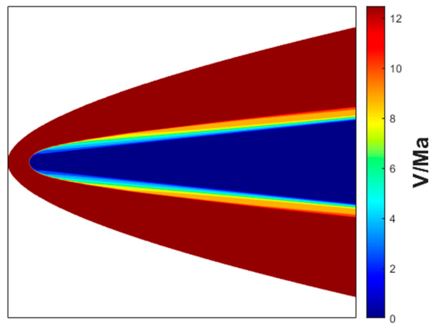
Taking the RAM-C blunt cone as an example, the plasma sheath enveloping a hypersonic vehicle exhibits distinct velocity distributions under various flight conditions at different altitudes, as depicted in Figure 2 [17].
The velocity distribution is characterized by radial attenuation properties: the velocity magnitude exhibits a surface-proximity dependency, with regions adjacent to the vehicle surface showing velocity synchronization approaching the vehicle’s bulk motion, while distal regions display progressively reduced velocities. Figure 2 illustrates the velocity distribution of the plasma sheath flow field in the aircraft-fixed reference frame, where the vehicle is assumed to be stationary (velocity magnitude = 0 m/s).

2.2. Multi-Frame Lorentz Transformations for Plasma-Sheath Kinematics

In a cold, collisional plasma, the frequency-domain Drude conductivity model is given by:
σ ( ω ) = ε 0 ω p 2 j ω + v
The constitutive parameters are defined as follows [18]: ε 0 denotes the vacuum permittivity, ω p represents the plasma characteristic angular frequency, v indicates the plasma collision frequency. The relationship between the current density J and the electric field E is J ( ω ) = σ ( ω ) E ( ω ) . Transforming this into the time domain via the inverse Fourier transform yields a convolution integral:
J ( t ) = ε 0 ω p 2 exp ( v τ ) 0 t E ( τ ) exp ( v τ ) d τ
Following the Recursive Convolution (RC) method [19], this integral is discretized within the FDTD scheme. The key step involves approximating the electric field over a time step to obtain an efficient iterative update for the current density at time step n + 1/2 [16]:
J n + 1 / 2 = exp ( v Δ t ) J n 1 / 2 + ε 0 ω p 2 exp ( v Δ t / 2 ) E   Δ t
Equation (3) is the explicit form of the original Equation (4). It is a second-order accurate FDTD realization of the Drude dispersion model, which is then coupled with Maxwell’s equations to form the complete update system [20]. The FDTD update formulation for low-temperature collisional cold plasma dispersive media is expressed as [16,21]:
J s n + 1 / 2 = e v Δ t J s n 1 / 2 + Δ t e v Δ t / 2 ε 0 ω p 2 E s n E s n + 1 = E s n + Δ t ε 0 ( × H ) s n + 1 / 2 Δ t ε 0 J s n + 1 / 2 H s n + 1 / 2 = H s n 1 / 2 Δ t μ 0 ( × E ) s n
In Equation (4), H denotes the magnetic field intensity in the laboratory frame. The subscripts are defined as the spatial component indices (x,y,z) in the Cartesian coordinate system. The constitutive parameters are defined as follows: μ 0 corresponds to the vacuum permeability, and n specifies the time step index in the field update process. The iterative Maxwell equation formulation remains applicable to plasma dispersive media in moving coordinate systems. However, electromagnetic field updates are constrained to velocity-synchronized grid regions, where only fields sharing identical velocity components can be incorporated into the update formulations.
In Equation (4), the curl calculations necessitate electromagnetic field components from neighboring grid elements. However, velocity discrepancies exist between adjacent grids. The curl expansions for E x and H x components are incorporated into Equation (4), with detailed spatial position expressions explicitly defined in the formulation. For further details, see Appendix A.
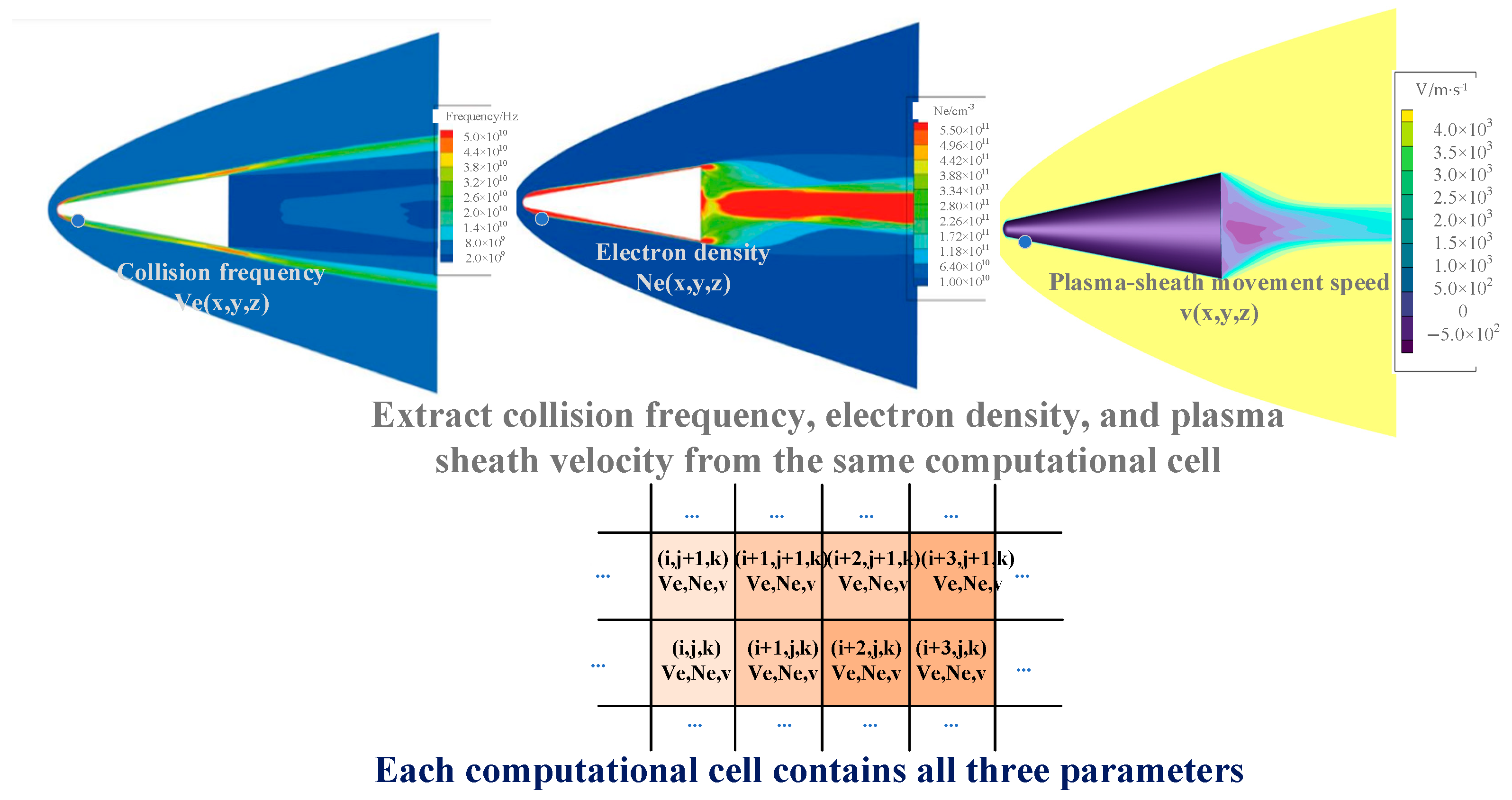
As illustrated in Figure 3, each computational cell within the plasma sheath contains three critical parameters: electron density, collision frequency, and sheath velocity. The depicted sheath velocity represents the relative velocity of the plasma sheath with respect to the vehicle, under the assumption that the vehicle is stationary (i.e., velocity = 0 m/s). The electron density and collision frequency within the plasma sheath are both non-uniform [22,23], and data from the literature are employed [17]. Conventional plasma sheath simulations have neglected this velocity component, whereas our improved methodology incorporates the sheath velocity into the established computational framework. The multi-frame Lorentz transformation method takes greater account of the influence of fluid velocity than traditional approaches. Consequently, it yields different results for echoes and electromagnetic scattering fields compared to conventional methods. This is demonstrated quantitatively in the results of the paper, where our results diverge significantly from those of traditional stationary-sheath models.
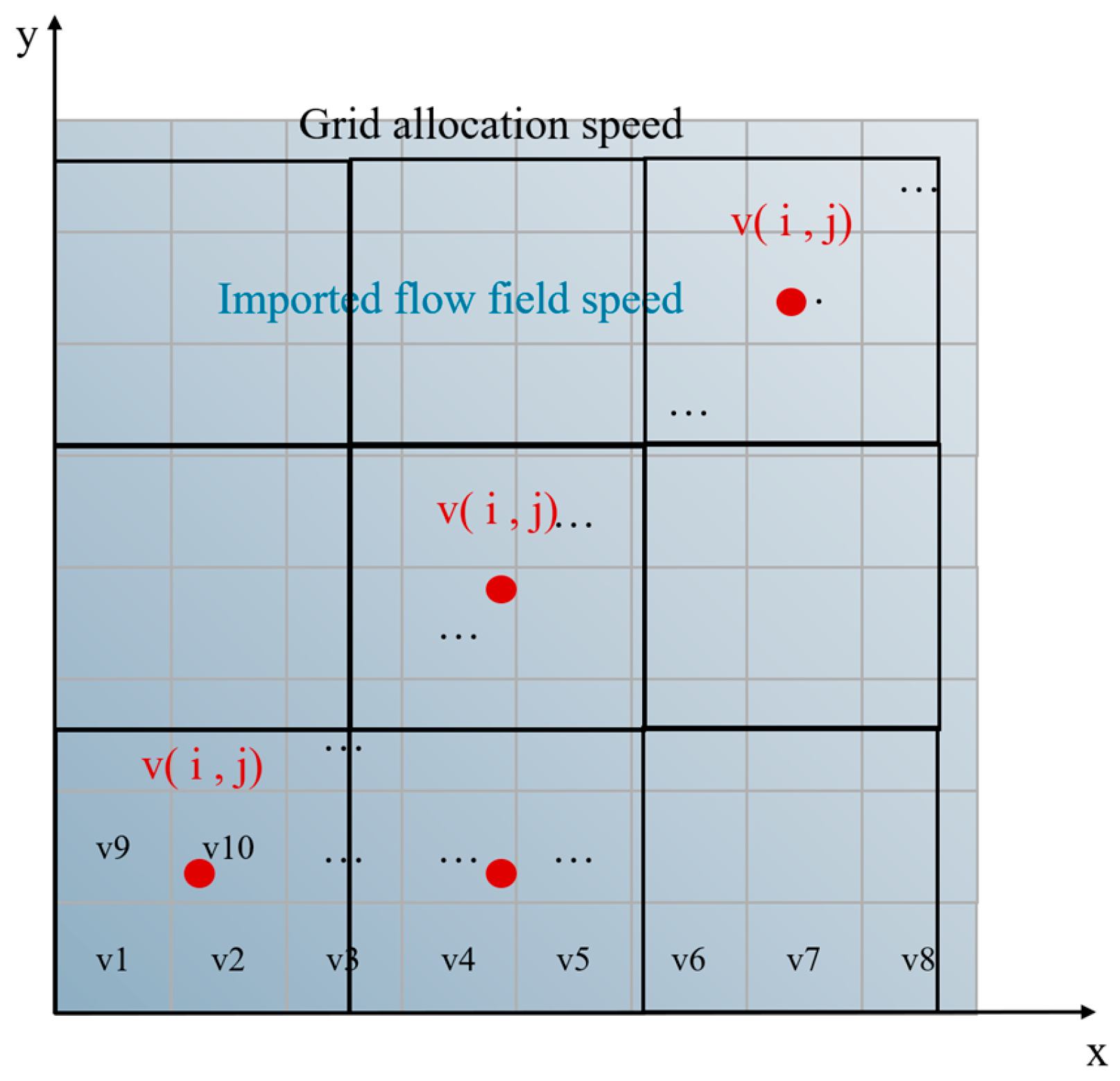
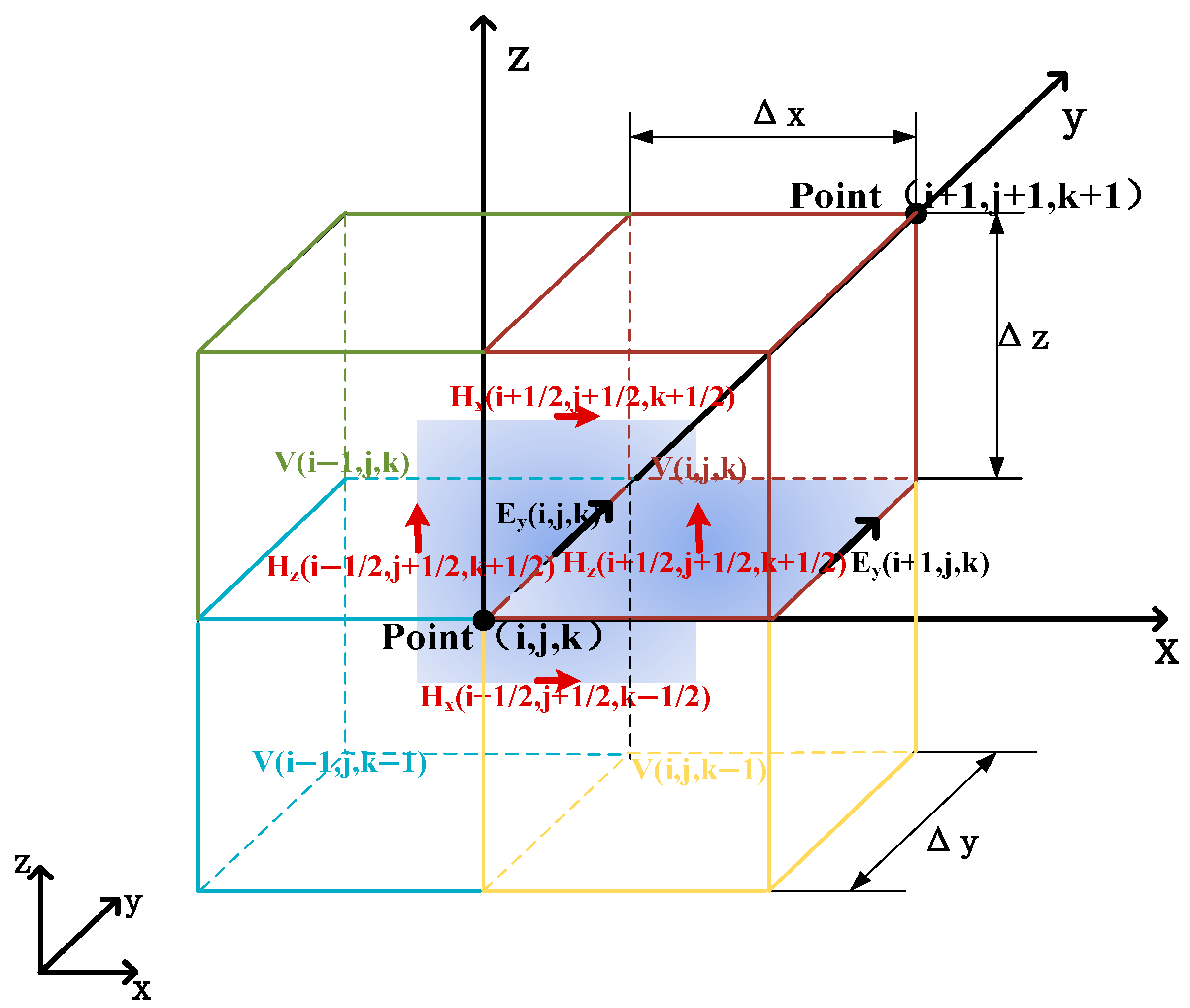
The velocity distribution v(i,j,k) for each grid cell is not computed internally but is imported from an external high-fidelity flow-field simulation dataset [17], which provides the plasma sheath properties. As illustrated in Figure 4, the central-value assignment scheme is employed, whereby the velocity value at the center of a Yee cell from the source data is assigned to the entire cell. This approach provides a consistent mapping of the non-uniform velocity field onto the FDTD grid.
H z ( i + 1 / 2 , j + 1 / 2 , k + 1 / 2 ) n + 1 / 2 = H z ( i + 1 / 2 + j + 1 / 2 , k + 1 / 2 ) n 1 / 2 Δ t μ 0 Δ x ( E y ( i + 1 , j , k ) v ( i , j , k ) n E y ( i , j , k ) n )
E y ( i , j , k ) n + 1 = E y ( i , j , k ) n Δ t ε 0 Δ x ( H z ( i + 1 / 2 , j + 1 / 2 , k + 1 / 2 ) n + 1 / 2 H z ( i 1 / 2 , j + 1 / 2 , k + 1 / 2 ) v ( i , j , k ) n + 1 / 2 ) Δ t ε 0 J y ( i , j , k ) n + 1 / 2
In Equations (5) and (6), i, j and k are defined as the spatial grid coordinates for positioning electromagnetic field components.
In the formulation, v ( i , j , k ) is defined as the local grid velocity at spatial coordinates ( i , j , k ) . The electromagnetic field components E ( i , j , k ) and H ( i + 1 / 2 , j + 1 / 2 , k + 1 / 2 ) represent the field quantities in the moving coordinate system associated with the grid velocity at v ( i , j , k ) . Specifically, E ( i + 1 , j , k ) v ( i , j , k ) denotes the electric field components corresponding to E ( i + 1 , j , k ) in the velocity v ( i , j , k ) coordinate system, and E ( i + 1 , j , k ) v ( i , j , k ) representing the electric field components corresponding to E ( i + 1 , j , k ) in the same velocity-conditioned transformation.
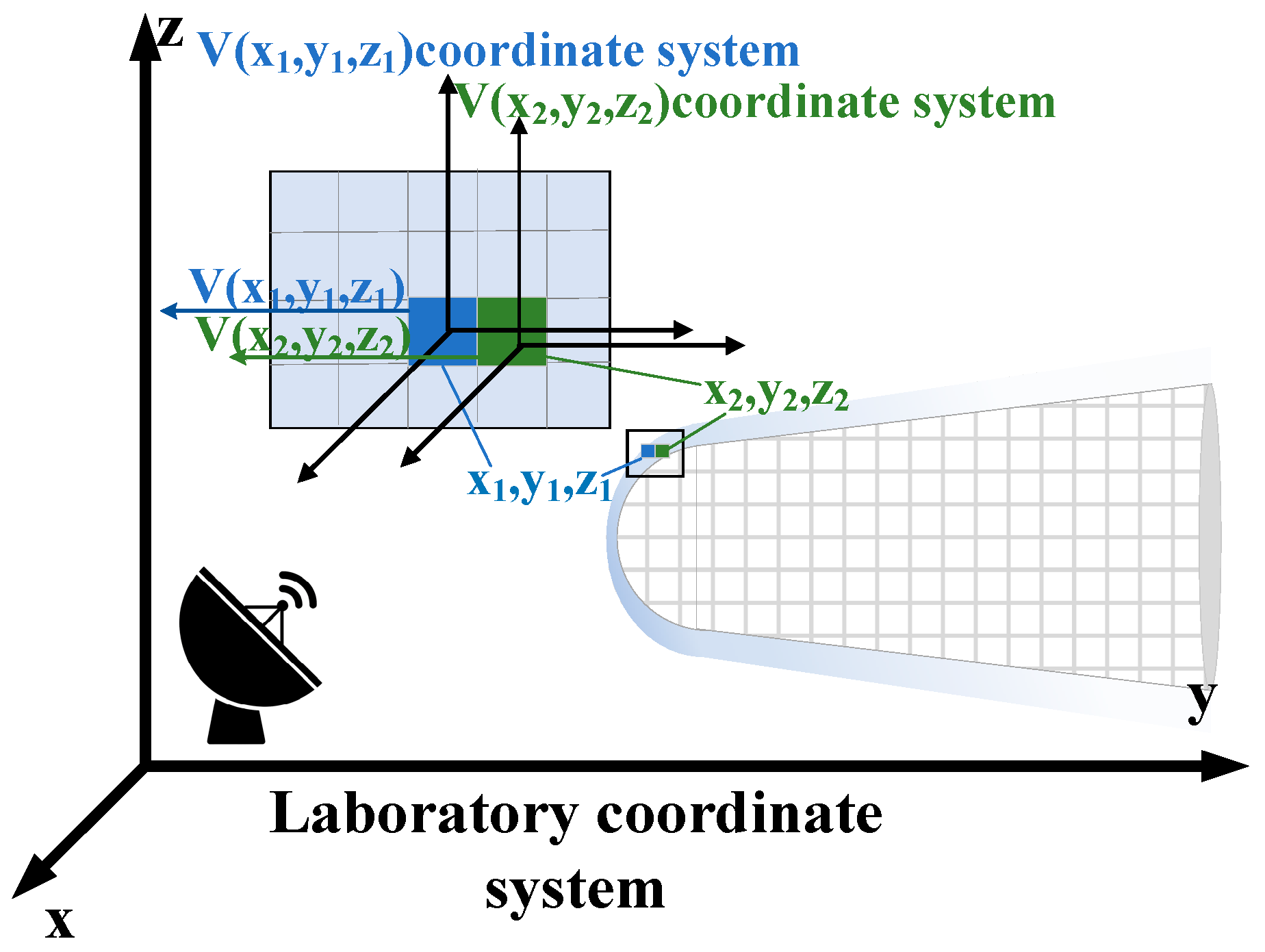
As is shown in Figure 5, the local electric field component E ( i + 1 , j , k ) is defined under grid velocity v ( i + 1 , j , k ) in the computational grid ( i + 1 , j , k ) .
The transformation of electromagnetic fields between the laboratory frame and the local rest frame of a grid cell moving with velocity v = ( v x , v y , v z ) is governed by the Lorentz transformation. The fundamental parameter for this transformation is the Lorentz factor, γ which accounts for relativistic effects of time dilation and length contraction [24]. For a cell with speed v = v , the Lorentz factor is defined as:
γ = 1 1 v 2 c 2
where c is the speed of light in vacuum.
The general vector form of the inverse Lorentz transformation, which converts the measured electric and magnetic fields from a frame moving with velocity v back to the laboratory frame, is given by [1]:
E = γ ( E - v × B ) + ( 1 γ ) v 2 ( v E ) v B = γ ( B + v × B c 2 ) + ( 1 γ ) v 2 ( v B ) v
This simplified expression (Equation (8)) serves as the continuous original formula for our method. In Equation (8), E and B denote the electric and magnetic fields in the stationary reference frame, while E’ and B’ denote the electric and magnetic fields in the moving reference frame.
Through inverse Lorentz transformation, these velocity-conditioned electric field components E ( i + 1 , j , k ) are transformed into laboratory-rest frame counterparts E ( i , j , k ) v ( 0 , 0 , 0 ) .
E ( i + 1 , j , k ) v ( 0 , 0 , 0 ) = γ v ( i + 1 , j , k ) ( E ( i + 1 , j , k ) + v ( i + 1 , j , k ) × B ( i + 1 , j , k ) ) + ( 1 γ v ( i + 1 , j , k ) ) E ( i + 1 , j , k ) v ( i + 1 , j , k ) v ( i + 1 , j , k ) 2 v ( i + 1 , j , k )
For a grid cell at position (i,j,k) with velocity v(i,j,k), the corresponding Lorentz factor is given by Equation (10). The Lorentz factor γ v ( i , j , k ) is defined as the relativistic parameter in the coordinate system moving with velocity v ( i , j , k ) [5]. The expression for γ v ( i , j , k ) in Equation (9) is:
γ v ( i , j , k ) = 1 1 v ( i , j , k ) 2 c 2
The electromagnetic field components are defined as follows:
E x ( i + 1 , j , k ) v ( 0 , 0 , 0 ) = γ v ( i + 1 , j , k ) v y 2 + v z 2 + v x 2 v 2 E x ( i + 1 , j , k ) + ( 1 γ v ( i + 1 , j , k ) ) v x v 2 E y ( i + 1 , j , k ) v y + E z ( i + 1 , j , k ) v z γ v ( i + 1 , j , k ) B z ( i + 1 , j , k ) y z B y ( i + 1 , j , k )
In Equation (11), v is represented as v ( i + 1 , j , k ) . Variables E y ( i + 1 , j , k ) v ( 0 , 0 , 0 ) and E z ( i + 1 , j , k ) v ( 0 , 0 , 0 ) maintain formal equivalence with E y ( i + 1 , j , k ) v ( 0 , 0 , 0 ) in Equation (11). The velocity components v ( i + 1 , j , k ) x , v ( i + 1 , j , k ) y and v ( i + 1 , j , k ) z are defined along the x, y, and z directions, respectively.
At grid position ( i 1 / 2 , j + 1 / 2 , k + 1 / 2 ) , the magnetic field component is defined as H ( i 1 / 2 , j + 1 / 2 , k + 1 / 2 ) with local grid velocity v ( i 1 , j , k ) .
Through inverse Lorentz transformation, this velocity-conditioned magnetic field component is converted to the laboratory-rest frame counterpart H ( i 1 / 2 , j + 1 / 2 , k + 1 / 2 ) v ( 0 , 0 , 0 ) .
H ( i 1 / 2 , j + 1 / 2 , k + 1 / 2 ) v ( 0 , 0 , 0 ) = γ v ( i 1 , j , k ) ( H ( i 1 / 2 , j + 1 / 2 , k + 1 / 2 ) + 1 c 2 v ( i 1 , j , k ) × E ( i 1 , j , k ) ) + ( 1 γ v ( i 1 , j , k ) ) B ( i 1 / 2 , j + 1 / 2 , k + 1 / 2 ) v ( i 1 , j , k ) v ( i 1 , j , k ) 2 v ( i 1 , j , k )
The electric field components are referenced at integer grid indices, whereas magnetic field components are referenced at half-integer grid indices. Consequently, the grid velocity corresponding to the magnetic field component ( i 1 / 2 , j + 1 / 2 , k + 1 / 2 ) is assigned as v ( i 1 , j , k ) . The explicit transformation for the electric and magnetic field components, which effectively constructs the transformation matrix, is given by [4]
E = γ ( E + v × B ) H = γ H v × D
where the primed fields denote values in the moving frame. The inverse transformation is applied after the field update to return to the laboratory frame.
The electric and magnetic fields in the laboratory stationary coordinate system are subjected to Lorentz transformations, respectively, converting them into the electric and magnetic fields in a moving reference frame with grid velocity (i,j,k).
E ( i + 1 , j , k ) v ( i , j , k ) = γ v ( i , j , k ) ( E ( i + 1 , j , k ) v ( 0 , 0 , 0 ) + v ( i , j , k ) × B ( i + 1 , j , k ) v ( 0 , 0 , 0 ) )
H ( i 1 / 2 , j + 1 / 2 , k + 1 / 2 ) v ( i , j , k ) = γ v ( i , j , k ) ( H ( i 1 / 2 , j + 1 / 2 , k + 1 / 2 ) v ( 0 , 0 , 0 ) v ( i , j , k ) × D ( i 1 , j , k ) v ( 0 , 0 , 0 ) )
Through an inverse Lorentz transformation followed by a Lorentz transformation, the target electric field E ( i + 1 , j , k ) v ( i , j , k ) and magnetic field H ( i 1 / 2 , j + 1 / 2 , k + 1 / 2 ) v ( i , j , k ) in the desired moving coordinate system are obtained. At this stage, the derived E and H correspond to the updated electric and magnetic fields required for the JEC-FDTD (current density convolution finite-difference time-domain) formulation in the moving grid under Multi-Frame Lorentz transformations.
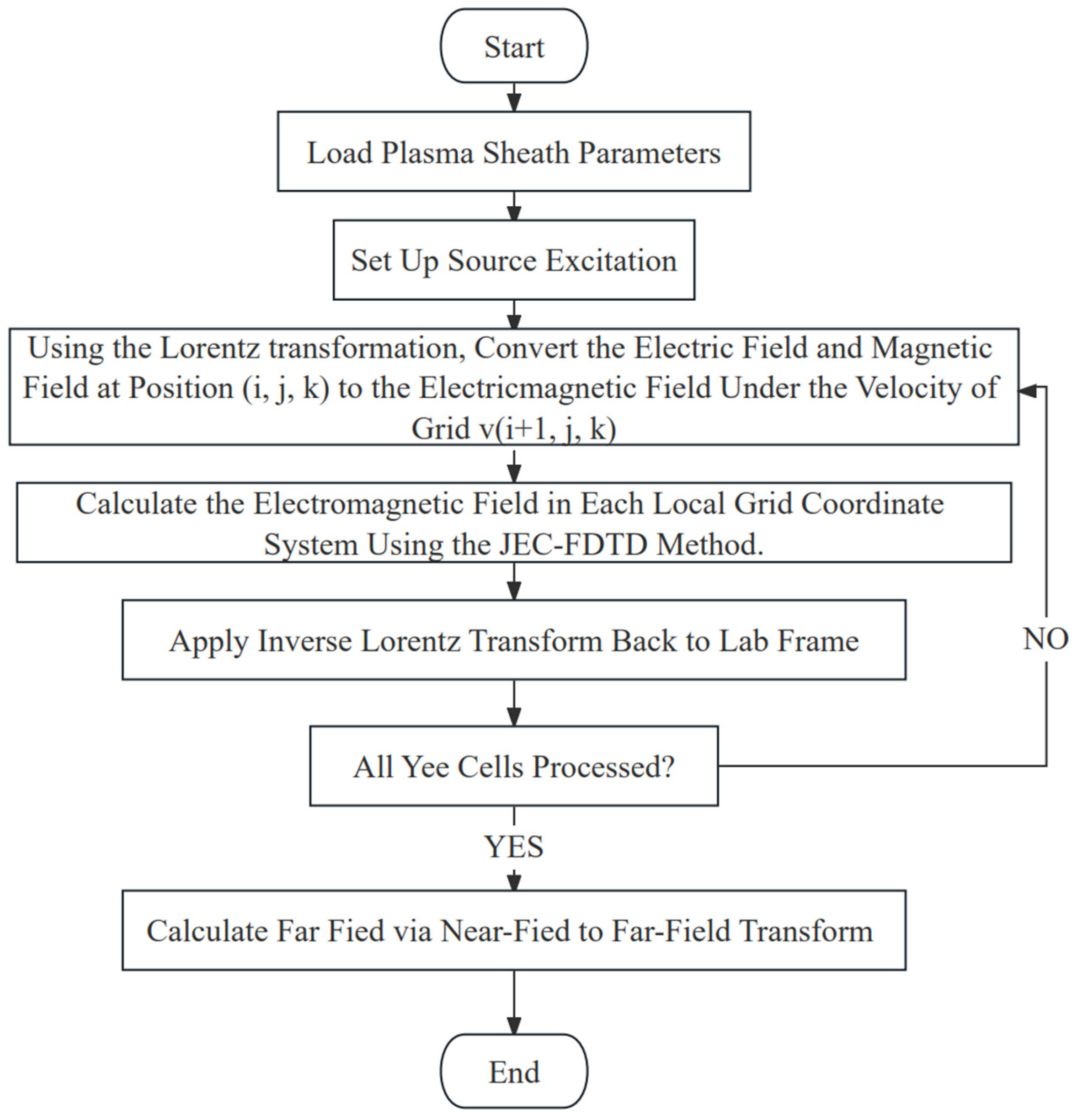
The Algorithmic workflow (Figure 6) depicts the operational pipeline of the multi-frame Lorentz method. It is initialized by loading the spatially varying plasma parameters. The core loop involves (1) transforming the EM fields into the local frame of each grid cell using its velocity, (2) performing the JEC-FDTD field update within this local frame, and (3) applying the inverse Lorentz transformation to return the updated fields to the laboratory frame, where the near-to-far-field transformation is ultimately performed. The proposed Multi-Frame Lorentz FDTD method introduces additional computational overhead compared to the single-reference-frame FDTD. The primary sources of increased complexity are twofold: (1) the application of a unique Lorentz transformation per cell, and (2) the management of electromagnetic field components across these frames. A preliminary analysis indicates that the computational cost per grid cell increases by approximately 25–35%, primarily due to the matrix operations involved in the Lorentz transformation. Memory usage also sees a proportional increase to store the velocity field and the intermediate transformed field components. Both the single-reference-frame FDTD and our multi-frame method scale linearly with the number of grid cells, O(N) (where N denotes the number of grid cells) in time per time step. The multi-frame approach introduces a constant factor to this linear scaling, but does not change the fundamental O(N) scaling. Similarly, memory consumption scales as O(N) for both, with the multi-frame method requiring additional O(N) storage for the velocity field.
To mitigate this overhead and enhance algorithmic efficiency, several optimization strategies can be employed in future implementations. Parallelization: The independent nature of the local transformations makes the algorithm highly amenable to parallel computing architectures, where the operations can be distributed across thousands of cores.

2.3. Radar Echo of Plasma-Sheath-Covered Target

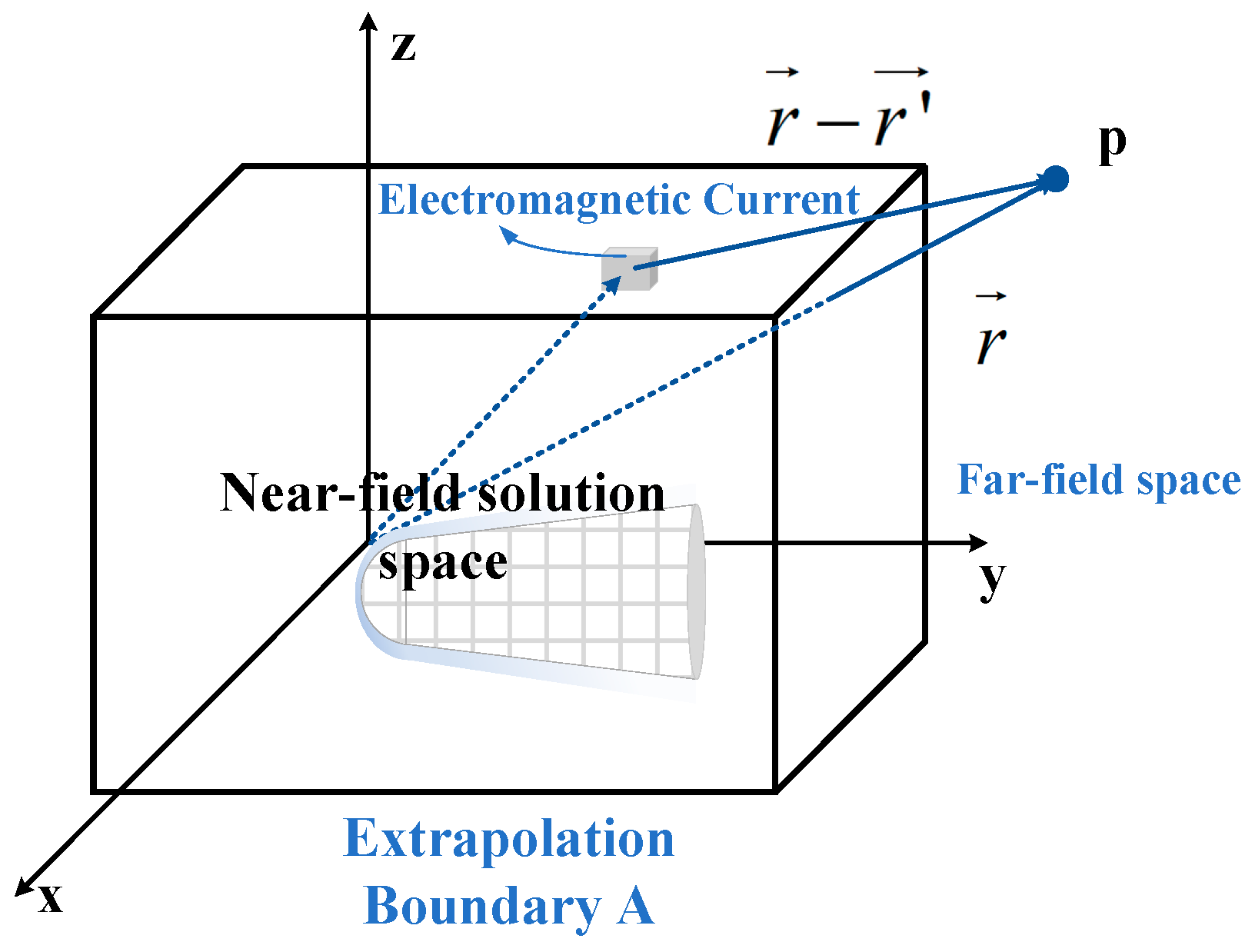
As shown in Figure 7, the schematic diagram illustrates the principle of near-to-far field transformation. The far-field scattered electromagnetic fields can be obtained through near-field data extrapolation [5].
Initially, a closed virtual boundary is established within the FDTD scattered-field region as the extrapolation boundary based on the equivalent extrapolation principle. The tangential current and magnetic flux densities on this virtual boundary are calculated and treated as independent radiation sources. Their far-field radiation contributions are subsequently computed.
The total far-field radiation from the extrapolation surface is derived through surface integration of the elemental current-induced radiation fields, which corresponds to the far-field scattering characteristics of plasma-sheath-covered targets [16]. The three-dimensional far-field formulation in moving coordinate systems can be expressed as:
E θ t = u x sin φ s u y cos φ s η w x cos θ s cos φ s + w y cos θ s sin φ s w z sin θ s
E φ t = u x cos θ s cos φ s + u y cos θ s cos φ s u z sin θ s + η w x sin φ s w y cos φ s
where η represents the free-space wave impedance w ( t ) and u ( t ) can be obtained by performing a Fourier transform on the following equations:
W = j k exp j k r 4 π r A n × H s exp j k r e r d s
U = j k exp j k r 4 π r A n × E s exp j k r e r d s
In the equations, r denotes the position vector of the observation point, e r represents the unit vector of r , and s corresponds to the scattered electromagnetic field along the r -direction. The far-field scattered components E θ , E φ and the moving coordinate system can be obtained via near-to-far-field extrapolation.
To simulate open-region wave propagation within a finite computational domain, Convolutional Perfectly Matched Layer (CPML) boundary conditions are employed [25]. A key consideration is the compatibility of CPML with the multi-frame Lorentz transformation framework. In this work, the CPML is implemented in the global laboratory reference frame. Although the fields within the plasma region are solved in local moving frames, the algorithm consistently transforms them back to the stationary laboratory frame at each time step (see Figure 6, Step 6). Consequently, the standard CPML formulation, which is designed for stationary boundaries, remains directly applicable and effective at the outer edges of the computational domain. This approach is well-established for problems involving moving media when the overall grid boundary is fixed [26].

3. Results

3.1. Doppler Effect

This section presents three case studies. The first case focuses on validating the accuracy and effectiveness of the proposed method through analyzing the Doppler effect induced by velocity. The second case investigates the reflection effects of electromagnetic waves caused by the one-dimensional motion of the plasma sheath. The third case examines the overall electromagnetic scattering characteristics of plasma-sheathed targets.
By employing Multi-Frame Lorentz transformations, the monostatic and bistatic electromagnetic scattering fields of a metallic sphere at various velocities are calculated.
A spherical structure with a radius R = 1 m is discretized in a computational domain characterized by spatial grid resolutions dx = dy = dz = 0.01 m, forming a 256 × 256 × 256 mesh configuration. Numerical solutions are obtained for Gaussian pulse excitation with both the incident wave propagation direction and the velocity vector aligned with the positive y-axis. Bistatic and broadband radar cross-section (RCS) analyses are conducted under three distinct velocity conditions: Ma = 15, Ma = 20, and Ma = 25, where Ma denotes the speed of sound in air.
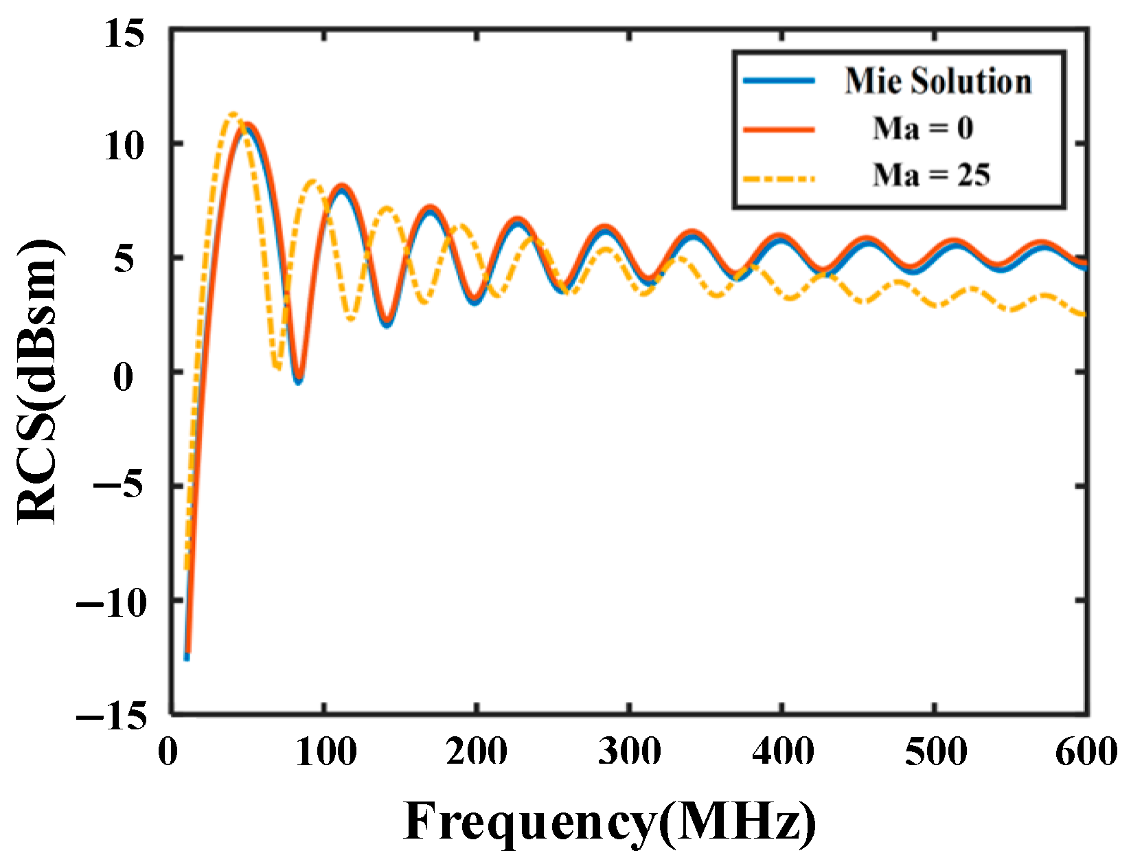
As illustrated in Figure 8, the Mie analytical solutions for spherical structures [27] serve as benchmark references. In this figure, the movement velocity is consistent with the direction of the incident wave. The computed RCS results show near-perfect agreement with these analytical solutions, thus definitively validating the computational effectiveness of the multi-frame Lorentz FDTD methodology. Notably, when the velocity reaches Ma = 25, the scattering fields of the metallic sphere exhibit significant deviations from those of its stationary counterpart. Specifically, a notable reduction in the overall RCS magnitude is observed at frequencies above 300 MHz.
Numerical simulations are conducted on the bistatic RCS of metallic spherical targets. Using the multi-frame Lorentz FDTD method, the bistatic RCS under the influence of plasma sheaths is analyzed at incident wave angles of 0° and 30°.
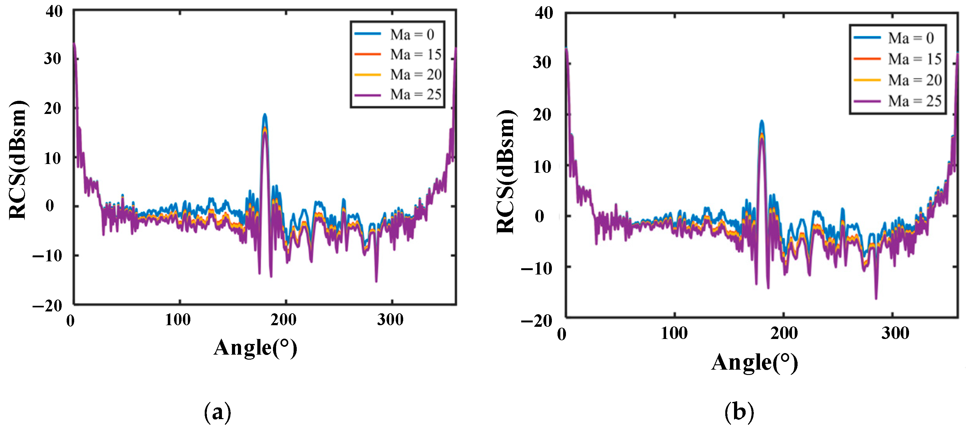
Figure 9a demonstrates that at normal incidence, the bistatic RCS exhibits velocity-dependent reduction characteristics: greater velocity magnitudes induce more pronounced RCS reduction, particularly at scattering angles near 180°. Compared to stationary conditions, minimal RCS variation is observed at 0° and 360° scattering angles. Figure 9b reveals analogous behavior for θ = 30° incidence, with maximum RCS reduction occurring near 210° scattering angles and negligible variation at the 30° scattering angle relative to static cases. This analysis confirms that RCS modulation vanishes when the incident and scattering directions coincide, while maximal reduction occurs when there is a 180° angular separation between the incident wave and scattering observation directions.
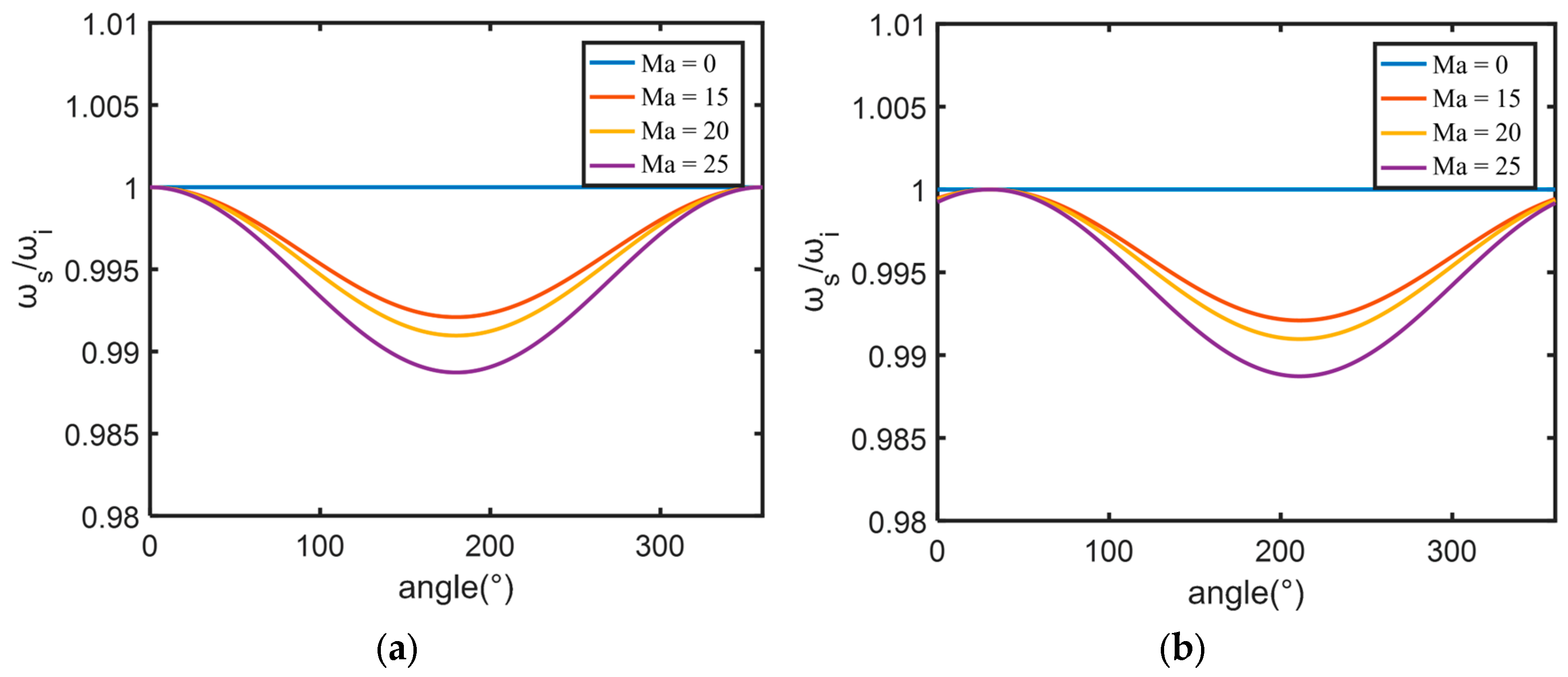
Figure 10a demonstrates the Doppler effects in scattered fields under velocities of 0, Ma = 15, Ma = 20 and Ma = 25 at an incident wave angle of θ = 0°. It is observed that no Doppler shift occurs in the forward scattering direction (θ = 0°). However, a prominent Doppler peak emerges in the backward scattering direction θs = 180°. Figure 10b illustrates the Doppler effects in scattered fields under identical velocity conditions at an incident wave angle of θ = 30°. The forward scattering direction (θ = 30°) exhibits no Doppler shift when the incident and scattering angles coincide. Conversely, a distinct Doppler peak is observed in the backward scattering direction at θ = 210°. These results confirm that Doppler effects vanish under collinear incidence-scattering configurations but reach maximum intensity under 180° angular separation between illumination and observation directions. In forward scatter, the Doppler effects on the incident and scattered paths cancel. In backward scatter, they add.

3.2. Moving Plasma Interacting with Metallic Plates

In the context of hypersonic vehicle operation at altitudes of 30–80 km, plasma parameters derived from existing literature specify electron densities ranging from 1014 to 1020 m−3 and collision frequencies spanning 108–1011 Hz. To systematically investigate the scattering characteristics of three-dimensional moving objects, preliminary analyses are performed on one-dimensional localized models. This study explicitly examines velocity-induced modulation effects on electromagnetic scattering during unidirectional motion. The numerical framework employs a differentiated Gaussian pulse with a frequency of 30 GHz as the incident wave, with plasma configurations analyzed using a 2 cm-thick plasma slab interacting with metallic substrates.
It is important to note that the plasma sheath model employed in the research of one-dimensional plasmas assumes a steady-state and uniform electron density distribution. In reality, hypersonic vehicle sheaths are highly turbulent and non-uniform [20,23].
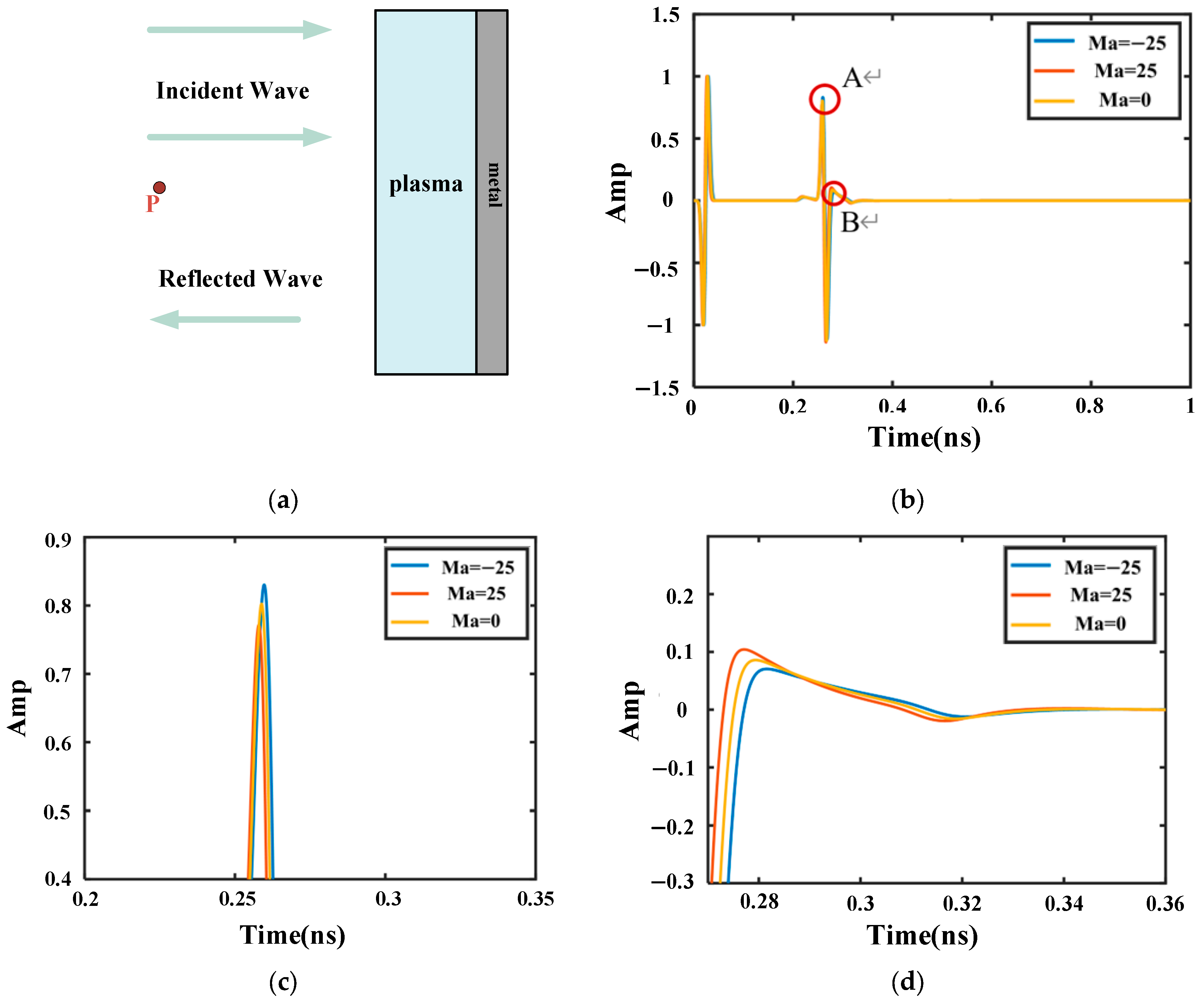
A reference point P exists in free space within the computational model. The multi-frame Lorentz transformation finite-difference time-domain (FDTD) method is employed to analyze this configuration.
Figure 11 presents numerical results under plasma conditions with electron density 1 × 10 14   m 3 and collision frequency of 20 GHz. The echo signals for stationary (0 velocity) and Ma = 25 conditions exhibit overlapping temporal profiles in Figure 11b, with field amplitude differences on the order of 10−3. Figure 11c demonstrates that at Ma = 25 velocity, the reflected waveform exhibits a forward temporal shift of approximately 10−3 ns compared to the stationary case, indicating reduced round-trip propagation time. Concurrently, the peak electric field amplitude decreases by 0.05 relative to stationary reflections. This phenomenon is attributed to relativistic Lorentz contraction between the moving plasma–metallic plate composite and the electromagnetic wave propagation direction. Conversely, at Ma = −25 velocity, a backward temporal delay of equivalent magnitude 10−3 ns occurs, accompanied by a 0.05 reduction in peak field amplitude compared to static conditions, consistent with relativistic time dilation effects under reverse motion.
While the metallic plate reflects most of the incident electromagnetic waves, partial wave-plasma interactions persist as the wave penetrates. The plasma layer absorbs a portion of the electromagnetic energy while re-radiating modified waveforms, with the secondary waveform peak corresponding to plasma-modified reflections. At observation point P, the electric field amplitude hierarchy follows Ma = 25, Ma = 0, and Ma =−25. This ordering arises from relativistic frame transformations during wave propagation through moving media: higher velocities induce earlier arrival of reflected components in the laboratory coordinate system. Specifically, the Ma = 25 motion causes accelerated wave reflection from the plasma–metallic structure, leading to the constructive superposition of multiple reflections in the laboratory frame.
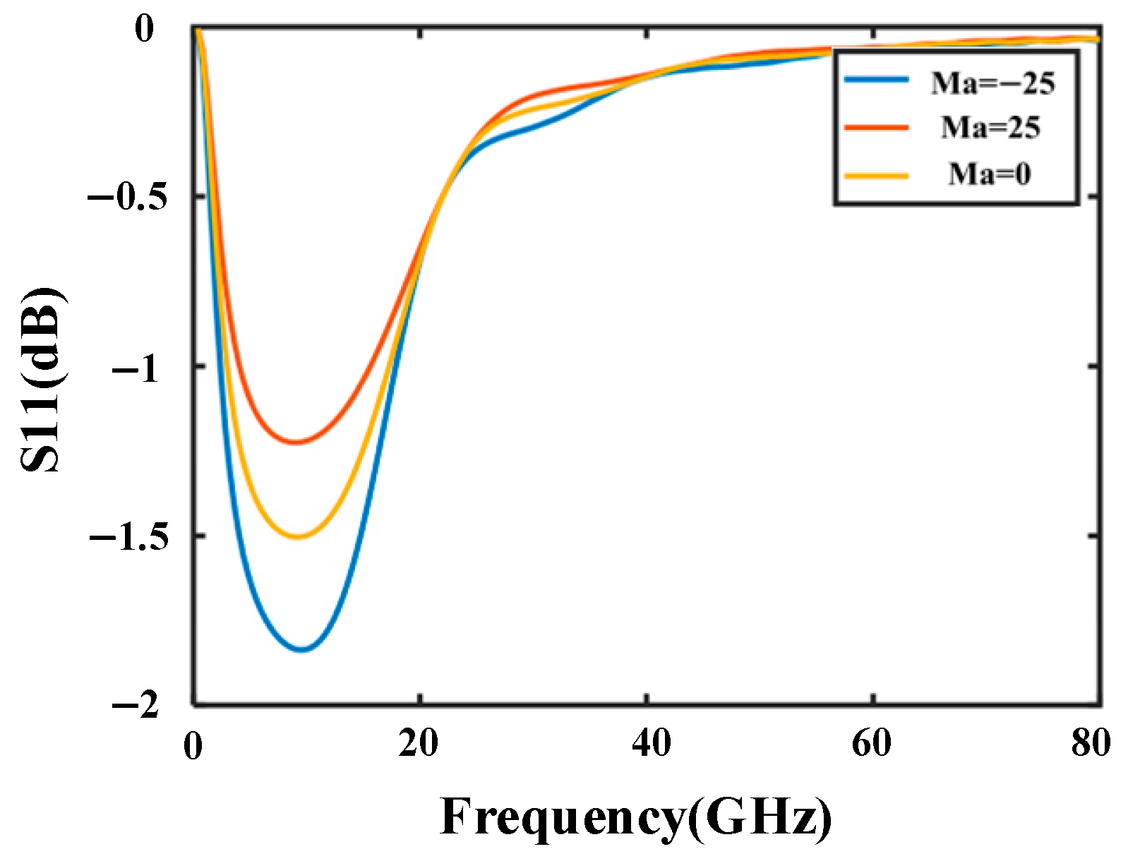
Figure 12 presents the reflection coefficient characteristics of electromagnetic waves interacting with the plasma–metallic plate structure. In the 0–20 GHz frequency range, the S11 parameter for the Ma = 25 case exhibits a 0.5 dB enhancement in reflection coefficient magnitude compared to stationary conditions (Ma = 0). Conversely, the Ma = −25 configuration demonstrates a 0.5 dB reduction in reflection coefficient magnitude relative to the static case. These observations indicate that forward motion (Ma = 25) enhances wave reflection efficiency through relativistic compression effects between the moving medium and incident waves, while reverse motion (Ma = −25) reduces reflection via temporal dilation mechanisms.
Above 20 GHz, all velocity configurations exhibit elevated reflection coefficients with increasing frequency. This frequency-dependent enhancement indicates that higher-frequency electromagnetic waves interact more strongly with the plasma-medium boundary, leading to amplified reflection coefficients irrespective of the motion state.

3.3. Validation and Analysis

To verify the accuracy and reliability of the method, we conducted a validation of the method on the model in Section 3.2.
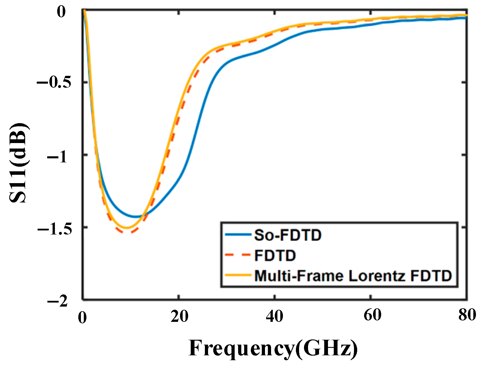
Figure 13 compares the S11 parameter of a one-dimensional model calculated using our Multi-Frame Lorentz FDTD, conventional FDTD, Shift-Operator (SO) FDTD [28], and the analytical solution. The agreement among all methods validates the accuracy of our proposed solver in modeling wave propagation in dispersive media, establishing a reliable baseline for analyzing complex plasma sheath effects.

3.4. Scattering Characteristics of the RAM-C Plasma Sheath Model

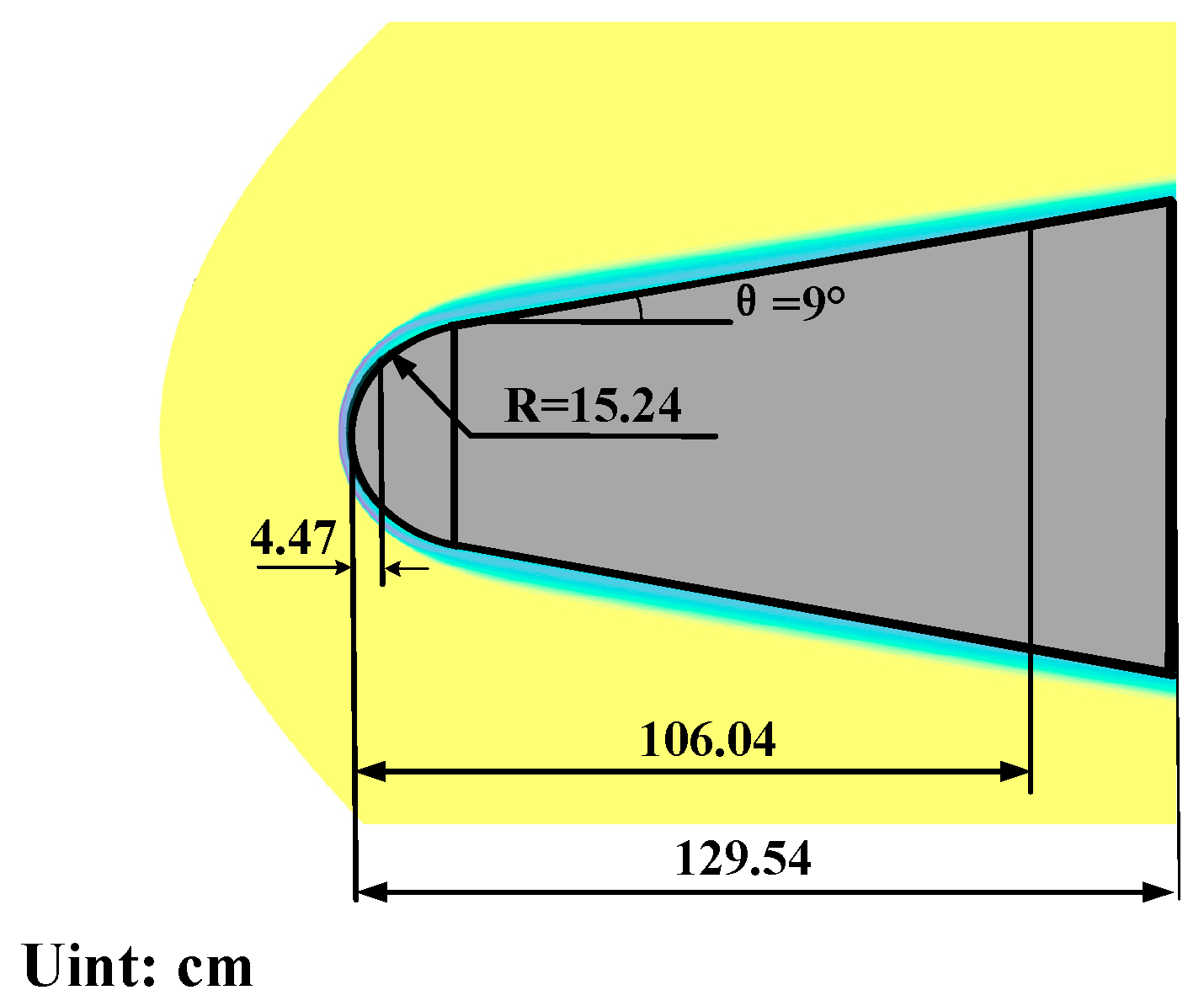
The scattering characteristics of the RAM-C configuration are numerically investigated using the multi-frame Lorentz transformation finite-difference time-domain method. As illustrated in Figure 14, the geometric dimensions of the simulation model employed in subsequent analyses are presented. The flow field data used in the electromagnetic (EM) calculations in this study are based on the numerical results of the flow field around a typical blunt-cone RAM-C reentry vehicle at different flight altitudes [17]. We employed the non-uniform plasma data from Reference [17] for the simulation. Subsequently, the EM calculation model of the plasma-sheath-covered blunt cone is established using a 3D linear interpolation method. The RAM-C II vehicle is used as the benchmark model in this study [29,30]. For the electromagnetic simulations, the vehicle’s surface is modeled as a Perfect Electric Conductor (PEC).
The properties of the encompassing plasma sheath, including the non-uniform distributions of electron density, collision frequency, and flow velocity, are imported in reference [17]. The plasma sheath thickness is inherently defined by these spatial distributions. Specifically, the electron density peaks at a characteristic standoff distance from the vehicle surface and decays outward, forming a layer of varying thickness along the body. The computational domain is discretized with spatial intervals of dx = dy = dz = 0.01 m, forming a 192 × 192 × 192 grid structure. Numerical solutions are computed for three velocity conditions: Ma = 0, Ma = 20, and Ma = 25, with incident wave parameters specified as follows: elevation angles of 0° and 15°; azimuth angles of 0° and 30°; and a horizontal polarization state. Subsequent electromagnetic scattering computations and analyses under varying velocities will be performed using experimental data of a plasma-sheath-covered hypersonic vehicle at an altitude of 30 km. For the purposes of this electromagnetic scattering study, the plasma velocity field is assumed to be a predetermined input, based on the established flow field data from [17].
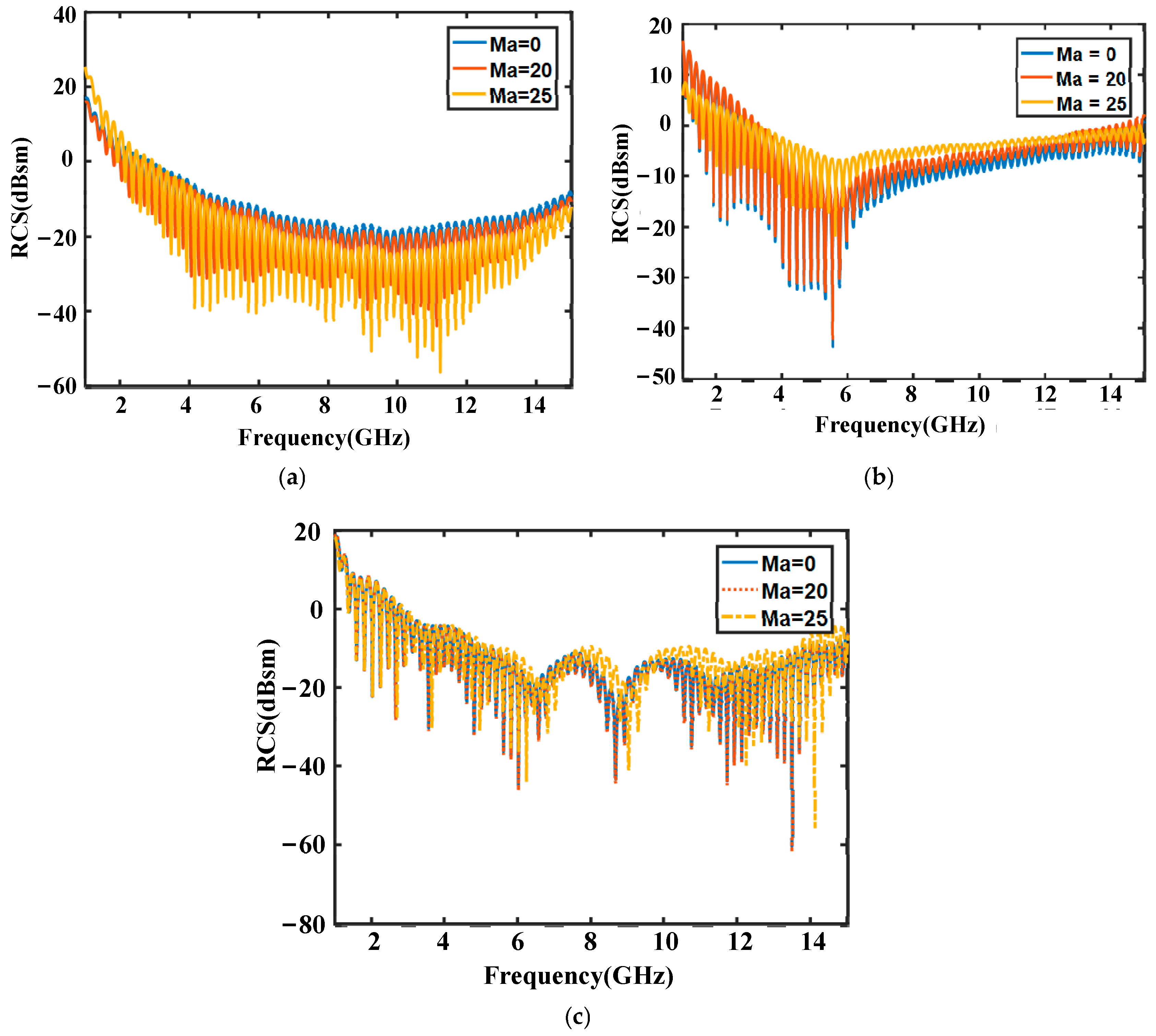
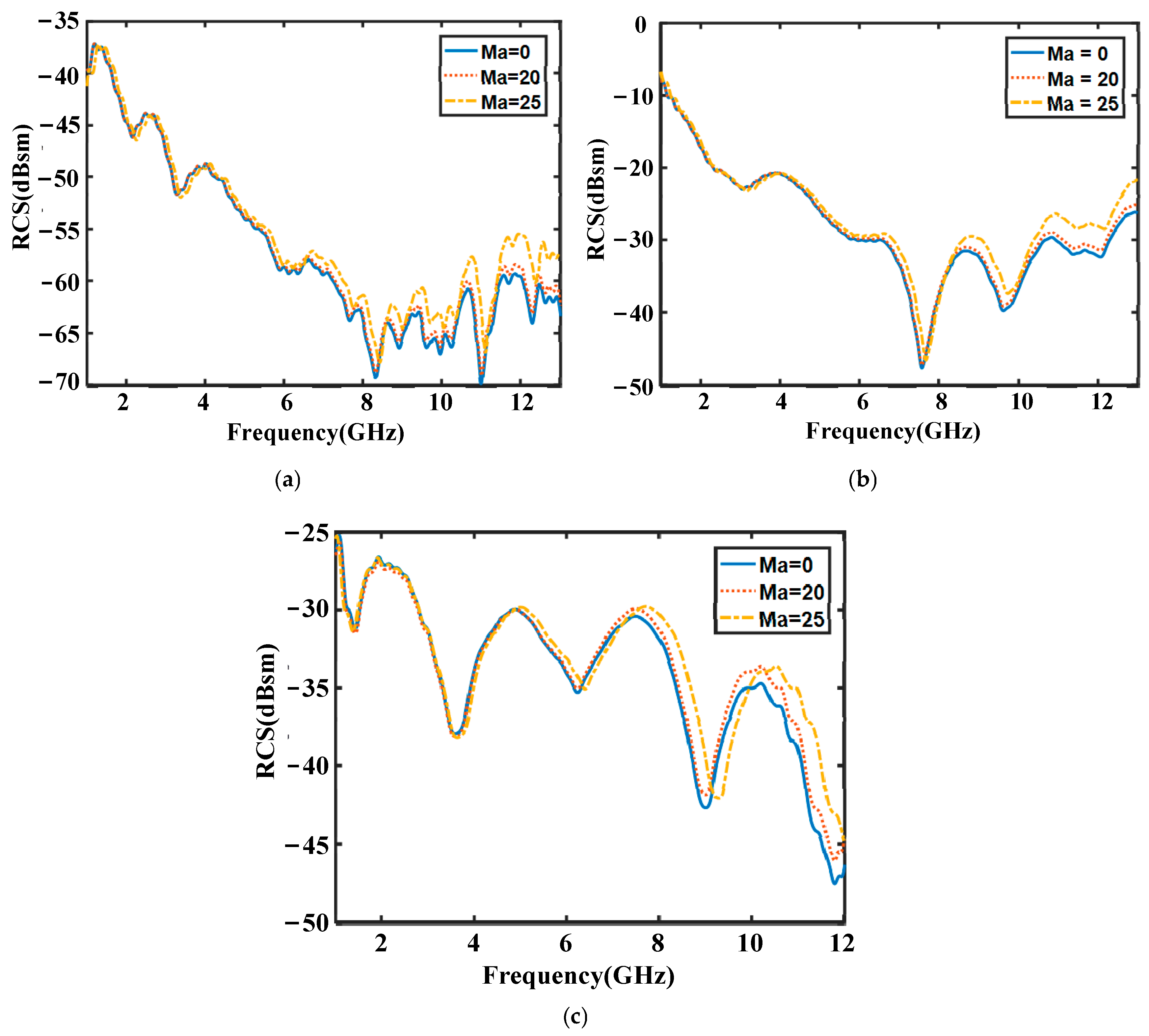
Figure 15a–c presents the co-polarized scattering results under horizontally polarized incident waves. For the Ma = 20 case, a measurable RCS reduction is observed in the low-frequency regime relative to stationary plasma sheath-encased targets, while frequencies exceeding 5 GHz exhibit an overall RCS enhancement. Similarly, when the velocity increases to Ma = 25, the overall trend remains comparable to that observed at Ma = 20. However, there is a noticeable difference in the magnitude of change. As the velocity increases, the impact on RCS becomes more pronounced.
Figure 16a–c presents the cross-polarized scattering results under horizontally polarized incident waves. For the Ma = 20 case, minimal RCS modification is observed in the sub-5 GHz frequency regime relative to stationary plasma sheath-encased targets, while frequencies exceeding 5 GHz demonstrate an overall RCS enhancement. Similarly, the Ma = 25 configuration shows RCS magnitudes comparable to those of the Ma = 0 cases at lower frequencies (<5 GHz). However, systematic RCS attenuation occurs across the frequency spectrum above 5 GHz compared to non-moving plasma sheath-encased targets. At frequencies above 5 GHz, the RCS value at velocities of Ma = 20 and Ma = 25 both increase, with an approximate increase of 3 dB. The monostatic RCS under nose-on incidence shows a pronounced decrease with increasing frequency, as presented in Figure 15a and Figure 16a. While a perfectly electric conducting (PEC) ram-air vehicle would exhibit a relatively stable RCS in the optical region, the enveloping plasma sheath introduces dominant attenuation. This is primarily due to enhanced absorption within the nose-cone region of the sheath, where the electron density and collision frequency peak. The high electron density raises the plasma frequency, increasing reflectivity and energy dissipation at the boundary. Concurrently, the elevated collision frequency significantly boosts the effective conductivity according to the Drude model, leading to substantial ohmic loss that converts wave energy into heat within the sheath, thereby reducing the backscattered signal.

4. Discussion

The proposed method is applicable within the following plasma parameter ranges: electron density from 1014 to 1020 m−3 and collision frequency from 108 to 1011 Hz. The velocity range extends from stationary conditions up to Mach 30. At very high electron densities (plasma frequency ≫ wave frequency), the sheath acts as a near-perfect conductor. While total reflection is captured, extreme wave attenuation inside the sheath may introduce numerical instability. At very low densities, sheath effects are negligible.
When the collision frequency dominates, the plasma behaves as a lossy conductor. Although the Drude model remains valid, rapid temporal variations in current density demand stricter FDTD time-step constraints. And if velocity gradients are too sharp across a single Yee cell, the local Lorentz transformation (assuming uniform cell velocity) may fail.
Under both horizontally polarized and co-polarized conditions, the motion velocity of the plasma-sheath-covered vehicle demonstrates negligible differences in its influence on RCS across various incidence angles. Furthermore, higher plasma sheath velocities consistently enhance the RCS of the target at all observation angles. For horizontally polarized incidence, a moving plasma-sheath-covered target exerts stronger modulation effects on cross-polarized (XP) components than on co-polarized returns. High-velocity plasma sheaths may disrupt the inherent structural symmetry of the target, thereby suppressing co-polarized (Co-Pol) scattering from originally symmetric configurations. The RCS and Doppler shifts observed in moving plasma sheaths are analyzed by examining modifications to the plasma’s effective refractive index and absorption coefficient. The motion-induced changes in electron density distribution alter phase accumulation and energy dissipation, leading to frequency shifts and amplitude damping consistent with plasma dispersion theory. This study focuses on electromagnetic scattering modulated by a known plasma velocity field, establishing a multi-frame Lorentz-FDTD foundation. To enhance model accuracy, we have put forward the following ideas regarding the direction of future research.
First, toward a multi-physics framework. Integrating thermal-fluid dynamics is good, as local temperature affects electron density and collision frequency. Here, machine learning offers a promising path for building efficient surrogate models [31,32]. Second, in regions of extreme velocity gradients, localized dispersion errors may persist. Machine-learned (ML) correction terms can be embedded into the FDTD update loop to compensate for velocity-induced dispersion during strong Lorentz frame transitions, improving accuracy efficiently. Furthermore, deep learning models can be trained as efficient surrogates to rapidly predict far-field scattering from plasma parameters or inversely infer plasma states from radiometric data, thus enhancing result analysis.

5. Conclusions

This paper proposes a multi-frame Lorentz JEC-FDTD methodology for analyzing the electromagnetic scattering characteristics of hypersonic vehicle configurations and plasma sheath models under relativistic motion. Complex geometries are simplified using planar and spherical analogs to simulate motion-induced electromagnetic interactions. The scattering properties of cone-shaped structures under various velocities are systematically summarized. For high-speed plasma–metallic composites, increased velocities correlate with enhanced reflected wave intensities and elevated reflection coefficients. In the three-dimensional plasma-sheath-covered RAM-C configuration, velocity-dependent upward shifts in RCS magnitude are observed, indicating a positive correlation between motion velocity and RCS enhancement.
This investigation establishes theoretical foundations for radar cross-section measurement, detection, and electromagnetic stealth optimization of hypersonic vehicles by computationally characterizing plasma sheath-covered targets under diverse kinematic conditions.

Author Contributions

Conceptualization, B.B. and Y.Y.; methodology, B.B. and Y.Y.; software, B.Z.; validation, B.P. and M.X.; resources, B.B.; data curation, B.Z.; writing—original draft preparation, Y.Y.; project administration, Y.L.; funding acquisition, X.L. All authors have read and agreed to the published version of the manuscript.

Funding

This research was funded by the National Natural Science Foundation of China, grant numbers 62171349, 92371205, and 62201430.

Data Availability Statement

The original contributions presented in the study are included in the article; further inquiries can be directed to the corresponding authors.

Conflicts of Interest

The authors declare no conflicts of interest.

Abbreviations

The following abbreviations are used in this manuscript:
FDTDFinite-Difference Time-Domain
RCSRadar Cross-Section
JEC-FDTDJE Convolution formulation of the Finite-Difference Time-Domain
RAM-CRadiowave Attenuation Measurement-C
CPMLConvolutional Perfectly Matched Layer
SO-FDTDShift-Operator Finite-Difference Time-Domain
PECPerfect Electric Conductor
XPcross-polarized
Co-Polco-polarized
MLmachine learning

Appendix A

In Equation (5), H z ( i + 1 / 2 , j + 1 / 2 , k + 1 / 2 ) n + 1 / 2 denotes the magnetic field in the z-direction at the spatial position (i + 1/2, j + 1/2, k + 1/2) when the step size is n + 1/2. E y ( i + 1 , j , k ) v ( i , j , k ) n denotes the electronic field in the y-direction at spatial position (i + 1, j, k) when the stride length is n, with the velocity field being v(i, j, k). Similarly, the superscript in the upper right corner denotes the step size, while the subscript in the lower right corner indicates the spatial position and velocity field of each electromagnetic field component.

References

  1. Zheng, K.-S.; Li, J.-Z.; Wei, G.; Xu, J.-D. Analysis of Doppler effect of moving conducting surfaces with Lorentz-FDTD method. J. Electromagn. Waves Appl. 2013, 27, 149–159. [Google Scholar] [CrossRef]
  2. Sahrani, S.; Kuroda, M. Numerical Technique for the Analysis of Electromagnetic Field by Moving Dielectric Body. IEEJ Trans. Fundam. Mater. 2013, 133, 255–259. [Google Scholar] [CrossRef]
  3. Zheng, K.; Li, Y.; Xu, L.; Li, J.; Wei, G. Electromagnetic Properties of a Complex Pyramid-Shaped Target Moving at High Speed. IEEE Trans. Antennas Propag. 2018, 66, 7472–7476. [Google Scholar] [CrossRef]
  4. Zheng, K.; Li, Y.; Qin, S.; An, K.; Wei, G. Analysis of Micro-motion Characteristics from Moving Conical-shaped Targets Using the Lorentz-FDTD. IEEE Trans. Antennas Propag. 2019, 67, 7174–7179. [Google Scholar] [CrossRef]
  5. Niu, G.; Liu, Y.; Bai, B.; Ding, Y. A Numerical Simulation Method of Radar Echo From a High-Speed Target. IEEE Antennas Wirel. Propag. Lett. 2021, 20, 1958–1962. [Google Scholar] [CrossRef]
  6. Niu, G.; Liu, Y.; Bai, B.; Ding, Y.; Song, L.; Li, X. Polarization Scattering Properties of Inhomogeneous Plasma-Covered Metal Plate. IEEE Trans. Plasma Sci. 2023, 51, 1232–1238. [Google Scholar] [CrossRef]
  7. Bai, B.; Zhao, D.; Chang, Z.; Ding, Y. Investigating Distribution Characteristics of Electromagnetic Reflection Intensity and Intrapulse Doppler Frequency Coupling Mechanism of Plasma-Sheath-Covered Target. IEEE Trans. Plasma Sci. 2025, 53, 220–229. [Google Scholar] [CrossRef]
  8. Ding, Y.; Bai, B.; Niu, G.; Li, X.; Liu, Y. A Radar Detection Method of Reentry Target Based on Frequency-Domain Processing. IEEE Trans. Plasma Sci. 2023, 51, 649–659. [Google Scholar] [CrossRef]
  9. Huang, K.; Xiao, Q.; Chen, J.; Dong, M. A Study on the Electromagnetic Characteristics of Very-Low-Frequency Waves in the Ionosphere Based on FDTD. Electronics 2025, 14, 1545. [Google Scholar] [CrossRef]
  10. Wang, Z.; Jiang, B.; Strokin, N.A.; Stupin, A.N. Study on plasma sheath and plasma transport properties in the azimuthator. Plasma Sci. Technol. 2018, 20, 045501. [Google Scholar] [CrossRef]
  11. Choroszucho, A.; Szczegielniak, T.; Kusiak, D. Application of the FDTD Method to Analyze the Influence of Brick Complexity on Electromagnetic Wave Propagation. Energies 2024, 17, 5168. [Google Scholar] [CrossRef]
  12. Fei, Z.; Yang, Y.; Jiang, X.; Zhao, Q.; Chen, X. Dynamic Electromagnetic Scattering Simulation of Tilt-Rotor Aircraft in Multiple Modes. Sensors 2023, 23, 7606. [Google Scholar] [CrossRef]
  13. Hellberg, M.A.; Mace, R.L. Generalized plasma dispersion function for a plasma with a kappa-Maxwellian velocity distribution. Phys. Plasmas 2002, 9, 1495–1504. [Google Scholar] [CrossRef]
  14. Lindner, H.; Murtazin, A.; Groh, S.; Niemax, K.; Bogaerts, A. Simulation and Experimental Studies on Plasma Temperature, Flow Velocity, and Injector Diameter Effects for an Inductively Coupled Plasma. Anal. Chem. 2011, 83, 9260–9266. [Google Scholar] [CrossRef] [PubMed]
  15. Yaroshevskaya, A.D.; Gutorov, K.M.; Podkovyrov, V.L.; Litvinenko, Y.I. Determination of Plasma Flow Velocity with Time Resolution Based on the Doppler Effect. Plasma Phys. Rep. 2024, 50, 689–696. [Google Scholar] [CrossRef]
  16. Chen, Q.; Katsurai, M.; Aoyagi, P.H. An FDTD formulation for dispersive media using a current density. IEEE Trans. Antennas Propag. 1998, 46, 1739–1746. [Google Scholar] [CrossRef]
  17. Chen, W.F.; Zhao, W.W. Rarefied Gas Dynamic Moment Method and Numerical Simulation; Science Press: Beijing, China, 2017; pp. 252–258. (In Chinese) [Google Scholar]
  18. Esposito, S.; Scarabosio, A.; Vecchi, G.; D’Ambrosio, D. Non-equilibrium plasma distribution in the wake of a slender blunted-nose cone in hypersonic flight and its effect on the radar cross section. Aerosp. Sci. Technol. 2024, 155, 109699. [Google Scholar] [CrossRef]
  19. Luebbers, R.J.; Hunsberger, F.; Kunz, K.; Standler, R.; Schneider, M. A frequency-dependent finite-difference time-domain formulation for dispersive materials. IEEE Trans. Antennas Propagat. 1990, 32, 222–227. [Google Scholar] [CrossRef]
  20. Lee, J.H.; Kalluri, D.K. Three-dimensional FDTD simulation of electromagnetic wave transformation in a dynamic inhomogeneous magnetized plasma. IEEE Trans. Antennas Propag. 1999, 47, 1146–1151. [Google Scholar] [CrossRef]
  21. Ge, D.; Yan, Y. The Finite-Difference Time-Domain Method for Electromagnetic Wave, 3rd ed.; Xi’an Electronic and Science University Press: Xi’an, China, 2011. (In Chinese) [Google Scholar]
  22. Petrova, T.B.; Petrov, G.M.; Peñano, J.R. Transport properties of high Mach number hypersonic air plasmas. Plasma Sources Sci. Technol. 2024, 33, 115008. [Google Scholar] [CrossRef]
  23. Yu, M.; Qiu, Z.; Zhong, B.; Takahashi, Y. Numerical simulation of thermochemical non-equilibrium flow-field characteristics around a hypersonic atmospheric reentry vehicle. Phys. Fluids 2022, 34, 126103. [Google Scholar] [CrossRef]
  24. Van Bladel, J.; Sessler, A.M. Relativity and Engineering; Springer: New York, NY, USA, 1984. [Google Scholar]
  25. Roden, J.A.; Gedney, S.D. Convolution PML (CPML): An efficient FDTD implementation of the CFS–PML for arbitrary media. Microw. Opt. Technol. Lett. 2000, 27, 334–339. [Google Scholar] [CrossRef]
  26. Foroutan, V.; Azarmanesh, M.N.; Foroutan, G. FDTD simulation of radar cross section reduction by a collisional inhomogeneous magnetized plasma. Phys. Plasmas 2018, 25, 023504. [Google Scholar] [CrossRef]
  27. Mie, G. Beiträge zur Optik trüber Medien, speziell kolloidaler Metallösungen. Ann. Phys. 1908, 25, 377–445. [Google Scholar] [CrossRef]
  28. Attiya, A.M.; Abdullah, H.H. Shift-Operator Finite difference Time Domain: An efficient unified approach for simulating wave propagation in different dispersive media. In Proceedings of the IEEE Middle East Conference on Antennas and Propagatio, Cairo, Egypt, 20–22 October 2010; pp. 1–4. [Google Scholar] [CrossRef]
  29. Surzhikov, S.T. Numerical Simulation of Air Ionization in the RAM-C-II Flight Experiment. Fluid Dyn. 2022, 57, S279–S298. [Google Scholar] [CrossRef]
  30. Evans, J.S.; Huber, P.W.; Schexnayder, C.J., Jr. The Entry Plasma Sheath and Its Effects on Space Vehicle Electromagnetic Systems. 19710011635. 2019. Available online: https://ntrs.nasa.gov/citations/19710011641 (accessed on 20 April 2025).
  31. Pratticò, D.; Laganà, F. Infrared Thermographic Signal Analysis of Bioactive Edible Oils Using CNNs for Quality Assessment. Signals 2025, 6, 38. [Google Scholar] [CrossRef]
  32. Laganà, F.; Pellicanò, D.; Arruzzo, M.; Pratticò, D.; Pullano, S.A.; Fiorillo, A.S. FEM-Based Modelling and AI-Enhanced Monitoring System for Upper Limb Rehabilitation. Electronics 2025, 14, 2268. [Google Scholar] [CrossRef]
Figure 1. Multi-coordinate systems across discretized grids.
Electronics 15 00161 g001
Figure 2. Velocity relative to the Hypersonic Vehicle.
Electronics 15 00161 g002
Figure 3. Parameters required for each grid in the computation of Hypersonic Vehicles.
Electronics 15 00161 g003
Figure 4. Schematic of the central-value assignment scheme for grid velocities.
Electronics 15 00161 g004
Figure 5. Mesh Discretization in Plasma Sheath Computations.
Electronics 15 00161 g005
Figure 6. Algorithmic workflow of Multi-Frame Lorentz transformation FDTD.
Electronics 15 00161 g006
Figure 7. Near-field to far-field transformation.
Electronics 15 00161 g007
Figure 8. Comparison of the RCS calculated by multi-frame Lorentz FDTD and Mie.
Electronics 15 00161 g008
Figure 9. Bistatic RCS of metallic spheres at different azimuth angles and velocities (a) θ i = 0 ° ; (b) θ i = 30 ° .
Electronics 15 00161 g009
Figure 10. Doppler frequency shift (a) θ i = 0 ° ; (b) θ i = 30 ° .
Electronics 15 00161 g010
Figure 11. The electromagnetic variation at a point P in the one-dimensional model of metal and plasma space. (a) Moving plasma–metallic plate composite structure; (b) Variation in electromagnetic wave; (c) E at observation point A; (d) E at observation point B.
Electronics 15 00161 g011
Figure 12. The reflection coefficient at a point P in the one-dimensional model of metal and plasma space.
Electronics 15 00161 g012
Figure 13. Comparison of S11 Parameter in the one-dimensional model of metal and plasma space using Multi-Frame Lorentz and conventional FDTD methods.
Electronics 15 00161 g013
Figure 14. Dimensional parameters of the plasma-sheath-enveloped RAM-C vehicle.
Electronics 15 00161 g014
Figure 15. Radar cross section (RCS) under HH-polarization (a) θ = 0 ° , φ = 0 ° ; (b) θ = 0 ° , φ = 30 ° ; (c) θ = 15 ° , φ = 0 ° .
Electronics 15 00161 g015
Figure 16. Radar cross section (RCS) under HV-polarization (a) θ = 0 ° , φ = 0 ° ; (b) θ = 0 ° , φ = 30 ° ; (c) θ = 15 ° , φ = 0 ° .
Electronics 15 00161 g016
Disclaimer/Publisher’s Note: The statements, opinions and data contained in all publications are solely those of the individual author(s) and contributor(s) and not of MDPI and/or the editor(s). MDPI and/or the editor(s) disclaim responsibility for any injury to people or property resulting from any ideas, methods, instructions or products referred to in the content.