1. Introduction
Active Magnetic Bearings (AMBs) provide several advantages, including frictionless operation, suitability for high-speed applications, and extended service life [
1]. High-speed motors incorporating AMBs are characterized by their compact size and high-power density. Consequently, AMBs are extensively employed in high-speed rotating machinery, such as turbomolecular pumps, compressors, flywheel energy storage systems, and other similar applications [
2].
When a magnetic levitation motor operates, the stator generates an electromagnetic field that interacts with the rotor’s magnetic field, producing an electromagnetic force that enables the rotor to levitate and rotate at high speeds, driven by a rotating magnetic field [
3]. However, factors such as uneven mass distribution within the rotor and unbalanced electromagnetic forces induce rotor vibrations [
4]. During operation, the direction and magnitude of the resulting centrifugal force continuously change, leading to irregular unbalanced vibrations of the rotor [
5]. In research on imbalance offsetting approaches, Chen [
6] proposed an unbalanced force suppression method for speed standard devices based on an active magnetic bearing force compensation system. A force feedback control system model with magnetic bearing as the force actuator is established, and a PI controller is designed to realize the control of disturbing force. Wu [
7] introduced the least mean square (LMS) algorithm into PID control and proposed an unbalanced vibration control strategy based on real-time filtering compensation of rotor displacement signals, which eliminates vibration by filtering synchronous frequency and harmonic signals input to PID control. Li [
8] proposed a control strategy based on the inverse system decoupling method and μ-synthesis to decouple the four-degree-of-freedom state equations of an electromagnetic bearing rigid rotor system by using the decoupling method and model the subsystems by using the uncertain parameter ingestion method to obtain the optimal μ-controller. Gao [
9] proposed an optimized auto-Disturbance Control (ADRC) algorithm using supervised Radial Basis Function (SRBF) to supervise and improve the error elimination efficiency of Nonlinear State Error Feedback Rate (NLSEF). Cao [
10] established an experimental platform for rotor systems and trained LSTM networks using multiple sets of measured response data and simulation data of rotor imbalance positions to realize the accurate identification of imbalance positions at different rotational speeds. Zhang [
11] proposed a basic acceleration feedforward compensation (BAFC) algorithm to effectively suppress rotor vibration under both simple harmonic excitation and random excitation, leveraging online basic excitation data and a dynamic model of the rotor system. Cui [
12] developed an improved double second-order generalized integral frequency-locked loop (SOGI-FLL) method to suppress the synchronous vibration force generated by the active magnetic bearing system. This method adaptively estimates rotor speed based on the frequency of the perturbation signal caused by rotor mass imbalance. Han [
13] proposed a method to suppress unbalanced magnetic tension perturbations using a linear extended state observer (LESO) combined with an adaptive peak filter (APF), effectively mitigating perturbations across the entire speed range.
Currently, numerous rotor vibration control strategies rely heavily on accurate rotor speed information. However, traditional methods involving the installation of speed sensors have notable drawbacks, including a high risk of damage due to collisions with the rotor shaft. In light of this, speed and position prediction for the rotor control systems of magnetic levitation high-speed motors, without relying on speed sensors, has become a prominent research focus. Ramírez [
14] proposed a sensorless controller scheme to force the rotor speed to track the desired reference, maintaining the alignment of the rotor’s electrical and mechanical angles despite the variation of the load torque over time. Bai [
15] made several improvements to the traditional extended electric potential (EEMF) estimation algorithm. The key improvements included discretization compensation, high-frequency harmonic filtering, and real-time tuning of the phase-locked loop bandwidth to advance dynamic and steady-state motor control. Liang [
16] proposed an SPMSM rotor position estimation algorithm based on an improved super-twisted sliding mode observer (ISTSMO) and a second-order generalized integrator (SOGI) structure to enhance the stability and robustness of the sensorless control system of surface-mounted permanent magnet synchronous motors (SPMSMs). Xiao [
17] presented a numerical solution of the inverse electromotive force based on the transmission line model (TLM), which became a new application in the position sensor-less control of permanent magnet synchronous motors. Saha [
18] employed a modified magnetic flux observer combined with an adaptive frequency-synchronized reference frame phase-locked loop for position estimation. By utilizing stator flux information to determine the angular position of the rotor, this method enables sensorless variable-speed drives. Sun [
19] proposed a speed sensorless control strategy for switched reluctance motors and introduced an improved time-varying function sliding mode variable structure controller (TVSMSC). Experimental results demonstrated its high robustness and accuracy in rotor position estimation. Naderian [
20] developed an improved signal demodulation algorithm based on an enhanced phase-locked loop (EPLL). This algorithm, operating at high frequencies and exhibiting rapid dynamic characteristics, successfully estimated rotor position from standstill to low-speed ranges. While all of the aforementioned studies focus on improving sensor models and control methods to achieve speed estimation, they inevitably increase the complexity and design challenges of the control systems, making them less straightforward to regulate.
In order to solve the above problems, research is carried out on the speed estimation of AMB high-speed motors, and in view of the shortcomings of the traditional methods, a speed estimation model based on improved high-frequency square wave signal injection (HFSWSI) is proposed. The model enhances the observer of the high-frequency pulse array current injection technique by taking advantage of the obvious convex pole effect generated by the asymmetric magnetic circuit at low speed of the motor, injecting high-frequency signals through multiple signal processing techniques, and extracting the position error information in the high-frequency response signals in order to realize accurate speed estimation. In signal processing, focusing on iq information extraction simplifies the design of the speed observer and avoids the bandwidth limitation and hysteresis effect brought by the traditional filter. The method is validated in the simulation on the magnetic levitation high-speed motor platform, which shows excellent performance under different speed and load conditions and verifies the accuracy of the speed estimation of the improved HFSWSI method.
2. Rotor Rotation Speed Estimation Method for PMSM Based on HFSWSI
2.1. Principle Analysis of High-Frequency Square Wave Signal Injection Method
The voltage equation of the PMSM in the synchronous rotating coordinate system is given by
where:
,
are d-axis and q-axis voltages, respectively;
,
are d-axis and q-axis inductances, respectively;
,
are d-axis and q-axis currents, respectively;
is the stator resistance;
is the magnetic flux linkage of the permanent magnets;
is the angular velocity of rotation in the d-q coordinate system.
When the PMSM operates at low speed, the fundamental back electromotive force can be ignored. Simultaneously, after applying a high-frequency voltage, the resulting high-frequency inductive reactance is significantly greater than the stator resistance, allowing the stator resistance voltage drop to be disregarded. Consequently, the high-frequency voltage equation in the two isochronous rotating coordinate systems can be simplified as
where the subscript ‘
h’ denotes the high-frequency component of the corresponding variable;
denotes the time-derivative operator (
), equivalent to
in the frequency domain for steady-state sinusoidal systems.
The high-frequency square-wave voltage injection method is similar to the traditional high-frequency pulsating sinusoidal voltage injection method, in which a high-frequency voltage signal is injected into the
d-axis of the estimated rotor coordinate system. However, in this case, the injected signal is a square wave rather than a sine wave. The high-frequency pulsating square-wave voltage signal can be expressed as follows:
where
n is the sampling sequence,
is the estimated high-frequency pulsating square wave voltage injected in the stationary coordinate system, and
is the voltage magnitude.
Because the frequency of the injected signal is several times higher than the rotational speed frequency of the motor itself, and given that the resistance is much smaller than the reactance at high frequencies, the effect of
is neglected when only the carrier signal is considered. Based on (3), the purely inductive model of the high-speed motor is obtained:
where
is the estimated high-frequency voltage injected under the two-phase stationary coordinate system
,
the estimated high-frequency current injected under the two-phase stationary coordinate system
, and
is the inductance in the phase-stationary coordinate system
.
Substituting Equation (3) into the estimated rotor coordinate system gives
where
is the estimated inductance in the two-phase stationary coordinate system
. The specific expression for
is:
where,
,
.
Further organization of Equations (4) and (5) yields:
Substituting Equation (3) into the above expression yields:
Through the derivation of the high-frequency response current above, the expression for the high-frequency current response generated when the high-frequency square wave signal is injected has been obtained. Upon analysis, it can be observed that the expression for the high-frequency response current contains information about the rotor position of the magnetic levitation motor. By applying appropriate signal processing, the motor’s rotational speed can be determined. Therefore, the generated high-frequency current signal needs to be processed accordingly.
Sample
at the sampling moment and multiply it by
to obtain the demodulated carrier current
.
Substituting (6) into (4) gives:
where,
Through the derivation of the high-frequency response current above, the expression for the high-frequency current response generated when the high-frequency square wave signal is injected has been obtained. The specific schematic diagram is shown in
Figure 1.
2.2. Rotor Position Estimation Based on Luenberger State Observer
The rotor position error information is the same as the conventional rotating high-frequency injection method. Therefore, the rotor position can be estimated by an observer after extracting this variation, and the observer used in this paper is the Luenberger state observer. According to the equation of motion of PMSM, the relationship between the estimated rotational speed and the estimated load torque is
is:
where:
is the torque command;
is the load torque;
is the number of pole pairs;
is the rotational inertia.
The
can be approximated to be unchanged in 1 calculation cycle, and the rotor position, rotational speed, and load torque are selected as the state variables, and the system state equation is
where the input is the error signal e,
Accordingly, the block diagram of the Luenberger state observer for rotor position observation can be obtained as shown in
Figure 2. In practice, the estimated rotor position is obtained by directly using the q-axis current variation as input to the Luenberger state observer.
2.3. Processing of High-Frequency Current Signals
Upon analysis, it can be observed that the expression for the high-frequency response current contains information about the rotor position of the AMB motor. By applying appropriate signal processing, the motor’s rotational speed can be determined. Therefore, the generated high-frequency current signal needs to be processed accordingly. The design of the observer is the core part of the whole speed estimation system. It consists of the correct extraction of the high-frequency current response and appropriate signal processing to obtain accurate rotor position and speed information. The signal processing process can be divided into the following five steps:
Step 1: The
transformations are applied to obtain the two-phase static currents, as given by Equation (14):
Thus, the functions
and
are, respectively,
Step 2: Design the high-pass filter with the objective of retaining the high-frequency components in the current response signals while effectively filtering out the low-frequency speed signals originating from the magnetic levitation high-speed motor itself.
Step 3: Design the low-pass filter using the
-axis current expression, defined as
When the load current is taken into account, it is expressed as
Multiplying
by
eliminates the effect of
n, resulting in
The low-frequency signal component is retained, while the high-frequency component is filtered out, leaving only the part containing rotor position information.
Step 4: Rotor position detection is achieved through the outlier method.
Step 5: Estimation of rotational speed information is performed using the structure of the Luenberger observer, which is derived from the equations of motion governing magnetic levitation high-speed motor machinery.
where
represents the actual angular speed of the motor rotor.
represents the number of pole-pairs of the motor.
represents the electromagnetic torque, which is the driving torque generated by the internal electromagnetic action of the motor.
represents the damping coefficient related to the rotational speed.
Additionally, based on the electromagnetic torque equation, the equation is rewritten and used as an estimation variable to derive Equation (20):
If
, then
represents the actual speed, i.e.,
determines the speed estimation bias, which is compensated for by an error compensator. Therefore:
where
and
represent the proportional coefficient and the integral coefficient, respectively.
Thus, Equation (22) is derived:
Combining this with the electromagnetic torque equation yields .
2.4. Improved Signal Extraction Based on High-Frequency Square Wave Injection
The rotational speed estimation process of the rotational speed position observer, based on the outlier method design and the Luenberger design, suffers from the following two limitations:
- (1)
In the signal extraction process, the four filters limit the system’s bandwidth and may introduce a hysteresis effect on the processed signal, which reduces both the static and dynamic performance of rotational speed estimation, thereby affecting its accuracy.
- (2)
In the design of the observer using the outlier method for position signal processing, the model structure is relatively straightforward to build. However, the design process demands a deep understanding of the theoretical formulas, making it challenging. Implementation requires the acquisition of both id and iq signals.
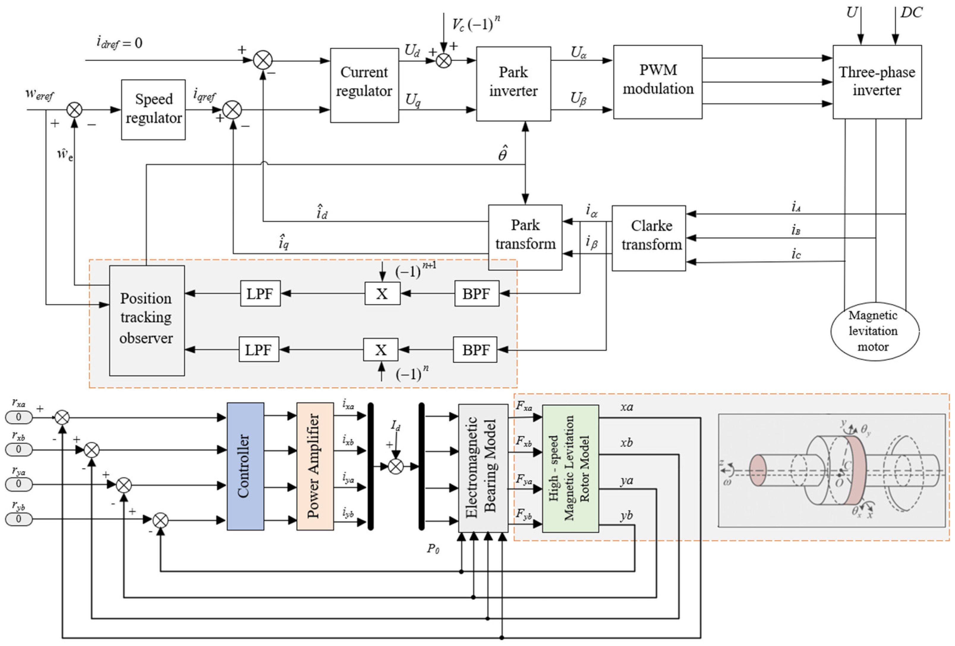
Based on the two aforementioned limitations, this section proposes an improved signal extraction method that can avoid the identified issues while maintaining the static and dynamic performance requirements of the system. This method greatly simplifies the structural design of the rotational speed observer and enables full-range rotational speed estimation. The concept of this improved approach is derived from the high-frequency pulse array current injection method, as the voltage response generated by high-frequency current injection contains rotor position information. A simpler signal extraction method, inspired by this current injection technique, is combined with the Luenberger structure for rotational speed estimation, with the signal extraction focusing solely on extracting the iq information. Based on the theoretical derivation in the previous chapter, the observer can be constructed as shown in
Figure 3, and the specific derivation process follows a similar approach to the high-frequency voltage injection method, which will not be repeated here.
In the observer design for speed estimation using the high-frequency current injection method, the challenge lies in extracting information about from the high-frequency voltage response, which requires advanced signal processing techniques. Although the principles behind various high-frequency injection methods are similar, the key difference lies in the observer design, which varies according to the different response signals, resulting in different methods for extracting rotor position signals. The constructed signal processing scheme has been verified through simulation. While it is capable of estimating rotational speed, the estimable rotational speed range is limited, and the static and dynamic performance is suboptimal. The main factor contributing to this is that the only adjustable parameter is ki, which significantly restricts the potential for improving system performance through parameter tuning.
4. Experimental Verification
The experimental rig of the AMBs rigid rotor system is shown in
Figure 9, which includes a monitor, power supply, power amplifier, controller, sensor, bearings, frequency converter, and AMBs high-speed motor. Where a power supply powers the device and a power amplifier receives and amplifies the controller signals. An eddy current sensor is used to measure the rotor displacement of the AMB motor in real time to collect data. The controller is based on the DSP28335 driver board, which processes the sensor data and generates control signals according to a preset algorithm. The display is connected to the host computer software to show the collected data in real time. The sampling rate of 20 kHz was selected, and the signal was processed by a low-pass filter with a cut-off frequency of 3 kHz. The sensitivity of the displacement sensor is 10 V/mm, and the maximum output current of the power amplifier is 10 A.
Figure 10 shows the floating process of the AMBs high-speed motor, and it can be seen that the rotor can be stably suspended. The first four traces represent the voltage variations in the radial directions (BY, AY, BX, AX), while the final trace corresponds to the axial (Z) direction. The horizontal axis is time (1 ms/div), and the vertical axis indicates voltage (2 V/div). Each trace is annotated with the maximum voltage (
Umax), minimum voltage (Umin), and average voltage (
Uavg) to highlight the dynamic behavior in each direction.
The setting central voltage (AX, AY, BX, BY) of rotor stable suspension is AX = 5.6 V, AY = 6.7 V, BX = 7.7 V, and BY = 8.1 V, respectively. During the initial phase (0 ms to 2 ms), the rotor remains in its natural state with no applied bias voltage, resulting in relatively stable voltage profiles across all directions. At 2 ms, a bias voltage is applied, initiating rotor motion. The radial voltage traces show a distinct transition, and the rotor achieves a stable levitation state approximately 1.8 ms later, with the voltage levels stabilizing for about 4.7 ms. At 8.5 ms, the bias voltage is removed, and the rotor returns to its natural state, with the voltage traces reverting to their initial values. The axial (Z-direction) response follows a similar trend, with the bias voltage applied at 4 ms, triggering motion in the axial direction. After approximately 0.2 ms, the rotor stabilizes in the levitation state by 4.3 ms, maintaining steady voltage for around 4.3 ms. The bias voltage is then removed at 8.5 ms, and the voltage returns to the natural state.
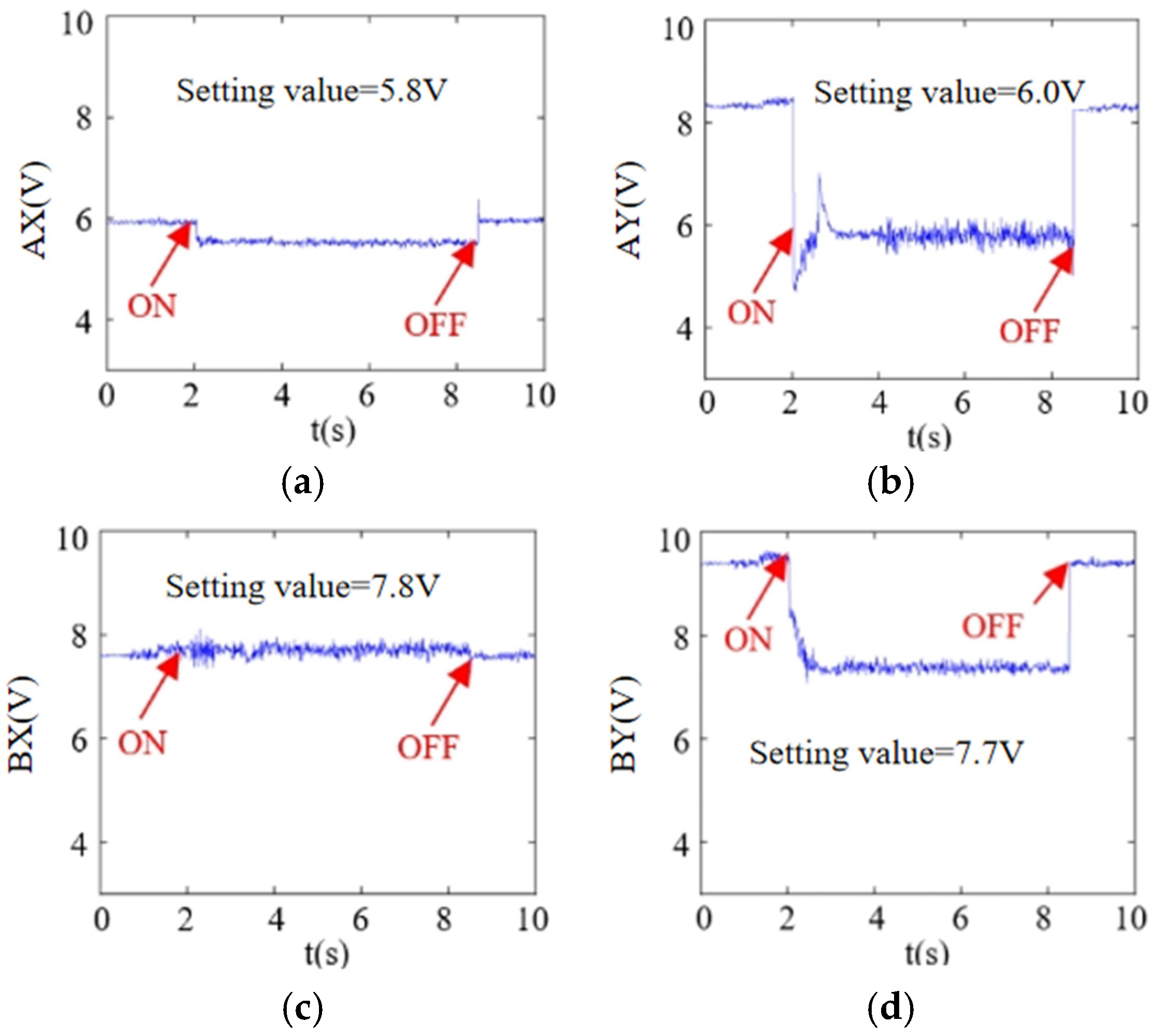
In order to further verify that the rotor can be stably suspended and change the rotor suspension center voltage (AX = 5.8 V, AY = 6.0 V, BX = 7.8 V, BY = 7.7 V), it can be seen from
Figure 11 that the rotor can be stably operated in the center position and the system has a good dynamic response.
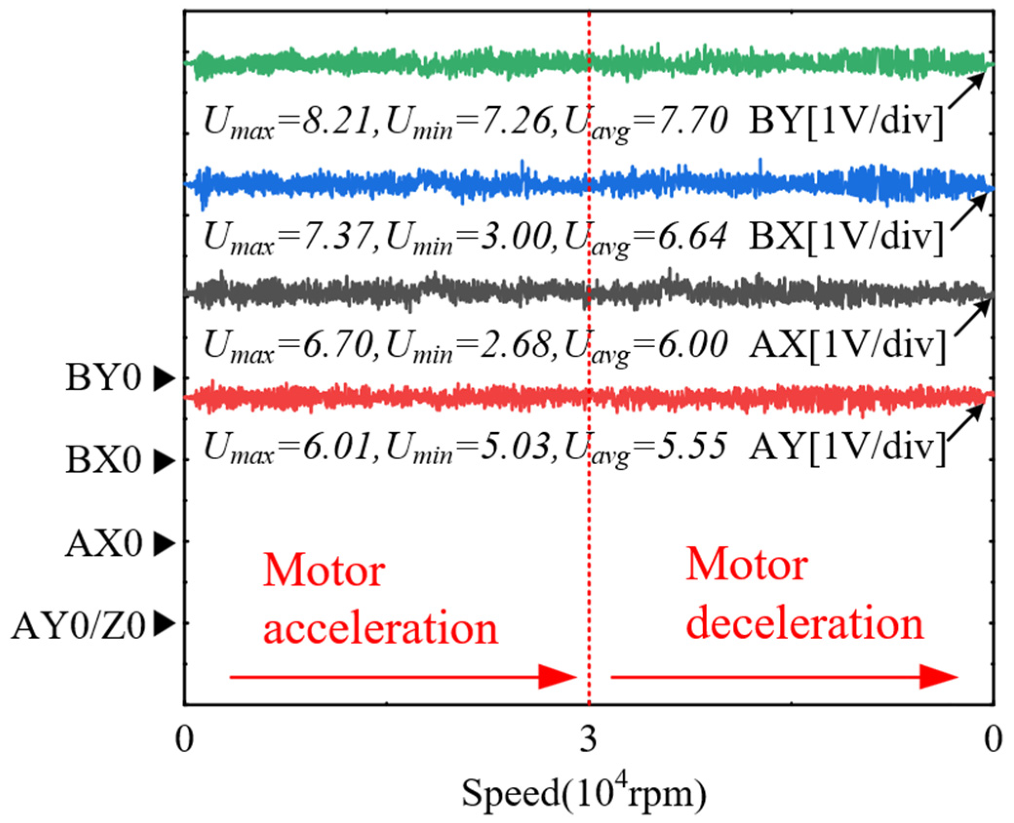
Figure 12 shows the current fluctuation characteristics of an AMB motor rotor during acceleration and deceleration at a high rotational speed of 45,000 rpm. Voltage measurements on each channel (AX, AY, BX, and BY) show that the system maintains a high degree of stability under high dynamic loads. For example, the average voltage (
Uavg) of the BY channel is 7.70 V with a small fluctuation range, showing good current control performance. In addition, the motor shows a strong dynamic response ability during acceleration and deceleration and is able to quickly adapt to speed changes, while the average voltage values of the channels are relatively stable, reflecting the reliability and high efficiency of the AMB system when operating at high speeds. These results provide strong experimental support for the further optimization of magnetic levitation motors in high-performance applications, proving their excellent performance under high-speed operating conditions.
By comparing and analyzing the experimental data of the four channels, the following conclusions can be drawn: The BY channel shows the highest average voltage and the smallest fluctuation range, indicating that the current control in this direction is the most stable and the system response performance is excellent. The fluctuation ranges of the BX and AX channels are larger, which indicates that the motor is subjected to larger dynamic loads during acceleration and deceleration in these directions, but the average voltage is still kept in a reasonable range. The average voltage of the AY channel is the lowest, showing better current control consistency. Overall, the BY direction has the best performance, while the BX and AX directions have larger fluctuations, but the system is still able to effectively cope with the dynamic changes in high-speed operation, which proves the overall stability and reliability of the magnetic levitation motor under the condition of high rotational speed.
5. Discussion
This paper proposes an improved signal extraction method that can avoid the identified issues while maintaining the static and dynamic performance requirements of the system. This method greatly simplifies the structural design of the rotational speed observer and enables full-range rotational speed estimation. The concept of this improved approach is derived from the high-frequency pulse array current injection method, as the voltage response generated by high-frequency current injection contains rotor position information. A simpler signal extraction method, inspired by this current injection technique, is combined with the Luenberger structure for rotational speed estimation, with the signal extraction focusing solely on extracting the iq information. In addition, compared with the permanent magnet synchronous motor, it fully takes into account the characteristics of the high speed of the magnetic levitation motor, solves the problem that the permanent magnet synchronous motor is easy to be damaged by the long-time high-speed operation, and provides a more reliable and efficient solution for the estimation of the speed of the magnetic levitation high-speed motor.
In the observer design for speed estimation using the high-frequency current injection method, the challenge lies in extracting information about from the high-frequency voltage response, which requires advanced signal processing techniques. Although the principles behind various high-frequency injection methods are similar, the key difference lies in the observer design, which varies according to the different response signals, resulting in different methods for extracting rotor position signals. The constructed signal processing scheme has been verified through simulation. While it is capable of estimating rotational speed, the estimable rotational speed range is limited, and the static and dynamic performance is suboptimal. The main factor contributing to this is that the only adjustable parameter is ki, which significantly restricts the potential for improving system performance through parameter tuning.


