Article

Assessment and Influencing Factor Analysis of Multi-Type Load Acceptance Capacity of Active Distribution Network

1
Dongguan Power Supply Bureau of Guangdong Power Grid Co., Ltd., Dongguan 523000, China
2
Department of Mechanical Engineering, North China Electric Power University, Baoding 071000, China
*
Author to whom correspondence should be addressed.
Electronics 2025, 14(8), 1566; https://doi.org/10.3390/electronics14081566
Submission received: 14 March 2025 / Revised: 31 March 2025 / Accepted: 10 April 2025 / Published: 12 April 2025

Abstract

:
With the increasing proportion of Distributed Generation (DG) in distribution networks and growing electricity business expansion demand, the integration of DG and new loads imposes significant impacts on distribution networks. To address the incomplete evaluation of active distribution network acceptance capacity, this paper proposes a multi-modal load acceptance capacity assessment methodology incorporating load growth patterns while comprehensively analyzing DG integration impacts. Firstly, differentiated load dynamic models are established to reveal the spatiotemporal distribution characteristics of multi-type loads. Secondly, a load growth model is presented based on spatiotemporal probability decomposition, accompanied by a multi-constraint acceptance capacity evaluation index system tailored to distribution networks. Moreover, an improved repetitive power flow method is developed, and a proposed acceptance capacity evaluation model is proposed to achieve the comprehensive evaluation of multi-type load acceptance capacity in active distribution networks. Finally, the effectiveness of the proposed acceptance capacity evaluation model is proven by a case study of an IEEE 33-node system, and multidimensional analysis is also conducted to investigate the impacts of DG type, DG installation location, DG proportion, and user-side energy storage system (ESS) access on the distribution network’s load acceptance capacity.

1. Introduction

With the increasing electricity demand and accelerating implementation of climate action initiatives, the coordinated development of high-penetration renewable energy integration and multi-load forms has become a core feature of modern power systems. As a critical carrier connecting Distributed Generation (DG) and end-users, Active Distribution Networks (ADNs) are undergoing a fundamental operational transformation from “unidirectional power flow” to “bidirectional interaction” [1,2,3]. As the core business process linking user demands with grid carrying capacity, the technical evaluation accuracy and process optimization level of business expansion services directly determine the acceptance efficiency of user loads in distribution networks [4,5,6]. Significant spatiotemporal differences exist among various load forms, particularly under high penetration of electric vehicle (EV) charging loads, which substantially impact distribution network operations through power quality degradation, transformer capacity overload, and increased network losses [7,8]. Current research predominantly focuses on static capacity verification in single-energy scenarios, while the integrated optimization of Hybrid Renewable Energy Systems (HRESs) demonstrates that multi-energy complementarity can significantly enhance system resilience by 10%. However, existing business expansion evaluation strategies insufficiently consider the dynamic coupling mechanisms between wind power generation-photovoltaic (WTG-PV) systems and loads, exacerbating resource mismatch risks [9,10,11].
Current research on distribution network load acceptance capacity primarily focuses on technical carrying capacity analysis and operational optimization. In business expansion-related domains, existing studies can be categorized into two groups: (1) static capacity verification methods based on power supply reliability; (2) dynamic access models considering temporal characteristics that evaluate intermittent load integration potential using probabilistic power flow calculations. Regarding load acceptance capacity assessment, Hua et al. [12] proposed a calculation method for EV charging acceptance capacity in residential distribution networks applicable to residential grids with arbitrary topologies. Ji et al. [13] reveal temporal–spatial matching characteristics between photovoltaic systems and EV charging loads in commercial office buildings, demonstrating a synergistic optimization mechanism where PV installation enhances EV acceptance capacity by 14.7% while reducing the transformer load rate by 23.4%. Li et al. [14] develop a risk-based operation optimization model to determine the maximum EV access quantity and establishes optimal EV admission limits through orderly charging strategies. While these studies construct optimization models for EV acceptance capacity assessment in specific scenarios, they prove unsuitable for conventional time-series load acceptance methods. Additionally, some scholars focus on power-source load acceptance capacity evaluation; Huang et al. [15] established a multi-objective optimization model to identify optimal DG locations and maximum acceptance capacity. He et al. [16] employed improved particle swarm optimization to maximize DG capacity under distribution network safety constraints. Considering long-term and short-term load fluctuation uncertainties, Yang et al. [17] established an optimal dispatch model balancing photovoltaic acceptance capacity and economic objectives, achieving maximum PV integration under economic constraints. These studies pursue maximum DG carrying capacity under economic objectives and operational constraints without adequately reflecting the operational constraint of the distribution network. Wu et al. [18] proposed a PV acceptance capacity evaluation method considering spatial correlations of adjacent distributed PV outputs, but it is unsuitable for load acceptance capacity calculations.
In order to achieve better load acceptance capacity calculations, other scholars employ statistical methods to construct acceptance capacity evaluation indices. Zhang et al. [19] developed a TOPSIS-based method for assessing EV acceptance capacity in distribution networks, proposing a comprehensive weighting method combining the Analytic Hierarchy Process (AHP) and entropy weight methods to evaluate acceptance capacity under different EV charging modes. Nevertheless, existing methods inadequately reflect distribution networks’ load acceptance capacity. Power flow calculations enable a comprehensive evaluation of network voltage, current, and losses, while repetitive power flow methods effectively determine carrying capacity under various constraint thresholds [20,21,22]. Kenedy et al. [23] successfully applied the repeated alternating current power flow approach to evaluate available transfer capability. Empirical studies on microgrid clusters reveal that DG integration alters power flow distribution, causing local overload issues [24,25].
Based on the above analysis, current load acceptance evaluation schemes lack dynamic response mechanisms, and business expansion assessment systems exhibit significant limitations: (1) insufficient consideration of multi-load acceptance characteristics, DG interaction mechanisms, and spatiotemporal complementarity effects leads to fragmented access decisions that may cause local overloads and resource mismatches and (2) DG integration alters power flow patterns, affecting original optimal access strategies.
As mentioned above, the main innovations and contributions include the following:
(1)
The development of a time-series load flow calculation model integrated with a probabilistic electric vehicle demand model employing the Monte Carlo method, which facilitates initial load generation and acceptance capacity computation in distribution networks.
(2)
The establishment of a load growth prediction framework combined with an improved repetitive power flow method specifically designed for multi-modal load acceptance capacity assessment, effectively addressing computational requirements for diverse load types.
(3)
A systematic investigation of DG-induced impacts on multi-modal load integration capabilities, including a quantitative analysis of load–network compatibility characteristics under predefined distribution network constraints, which provides operational guidance for supply expansion scheme optimization.
This paper proposes a rapid calculation method for load acceptance capacity in active distribution networks across various load integration scenarios, combined with case studies analyzing DG’s influencing factors. Firstly, a time-sequence power flow calculation model is established for multi-form loads and an electric vehicle demand model is constructed based on the probability distribution and Monte Carlo method. Secondly, an evaluation index system for acceptance capacity is developed considering multiple constraints, including voltage limits, current limits, and line capacity. A spatiotemporal probability decomposition-based load growth model is proposed. Moreover, an improved repeated power flow method-based evaluation model is established for assessing DG-integrated distribution networks’ load acceptance capacity under the spatiotemporal growth characteristics of multi-form loads. Finally, a case study of the IEEE 33-node system verifies the effectiveness of the proposed acceptance capacity evaluation model under the specified load growth pattern. The case study analyzes the factors affecting the acceptance capacity of the distribution network, including the types of DG, the proportion of DG, the access location of DG, and user-side ESS access.

2. Active Distribution Network-Distributed Generation Model

2.1. Distributed Generation Models

2.1.1. Wind Turbine Generation Power Flow Model

Grid-connected wind turbine generation (WTG) primarily consist of two types: constant-speed, constant-frequency (CSCF) WTGs and variable-speed, constant-frequency (VSCF) WTGs. In power flow calculations, CSCF WTGs are treated as PQ(V) nodes, analogous to asynchronous generators. For VSCF WTGs, they operate as PV nodes under constant voltage control mode and as PQ nodes under constant power factor control mode. In practical applications, doubly fed induction generators (DFIGs) typically adopt constant power factor control.

2.1.2. Photovoltaic Power Flow Model

During grid-connected operation, photovoltaic (PV) systems directly convert solar energy into DC power, and current-controlled inverters convert the DC power into AC power synchronized with the grid in frequency and phase. The PV grid-connected inverters primarily utilize voltage-source current control, where the inverter output current is regulated to track the grid voltage for achieving parallel operation. When the PV is connected to the grid, it can maintain a power factor of 1. Therefore, in power flow calculations, only active power needs to be considered and treated as a PQ node.

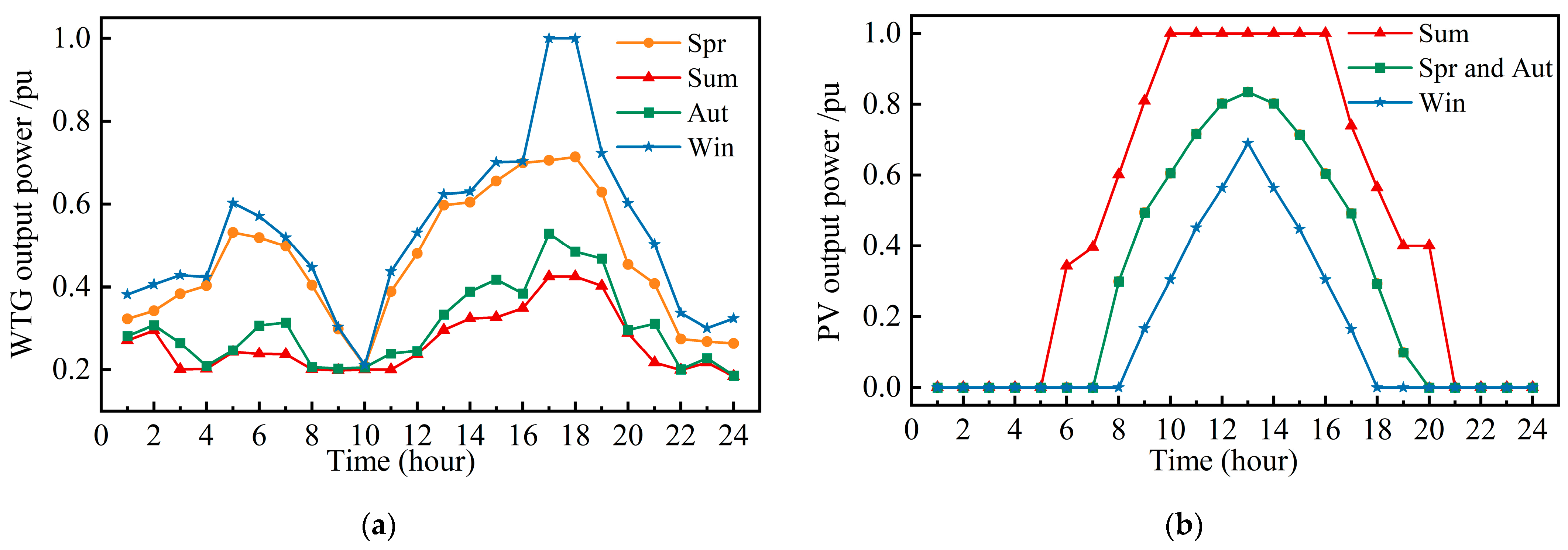
2.2. Distributed Generation Temporal Model

Microturbines are stable and controllable power sources with minimal output fluctuations, and this paper excludes them from further analysis. Wind and photovoltaic generation, however, exhibit prominent temporal and seasonal characteristics. The distinct temporal features of these sources differentially affect clean energy integration. Wind turbine output is predominantly influenced by wind speed variations, and PV output correlates with solar irradiance levels. Significant seasonal differences in wind speed and irradiance necessitate separate temporal profiles. Based on meteorological data from a city in southern China, seasonal wind speed and irradiance curves are derived, from which the temporal output profiles of WTGs and PV systems are calculated (Figure 1). The peak WTG output in winter and maximum PV output in summer are calculated from Figure 1.

3. Distribution Network Load Model

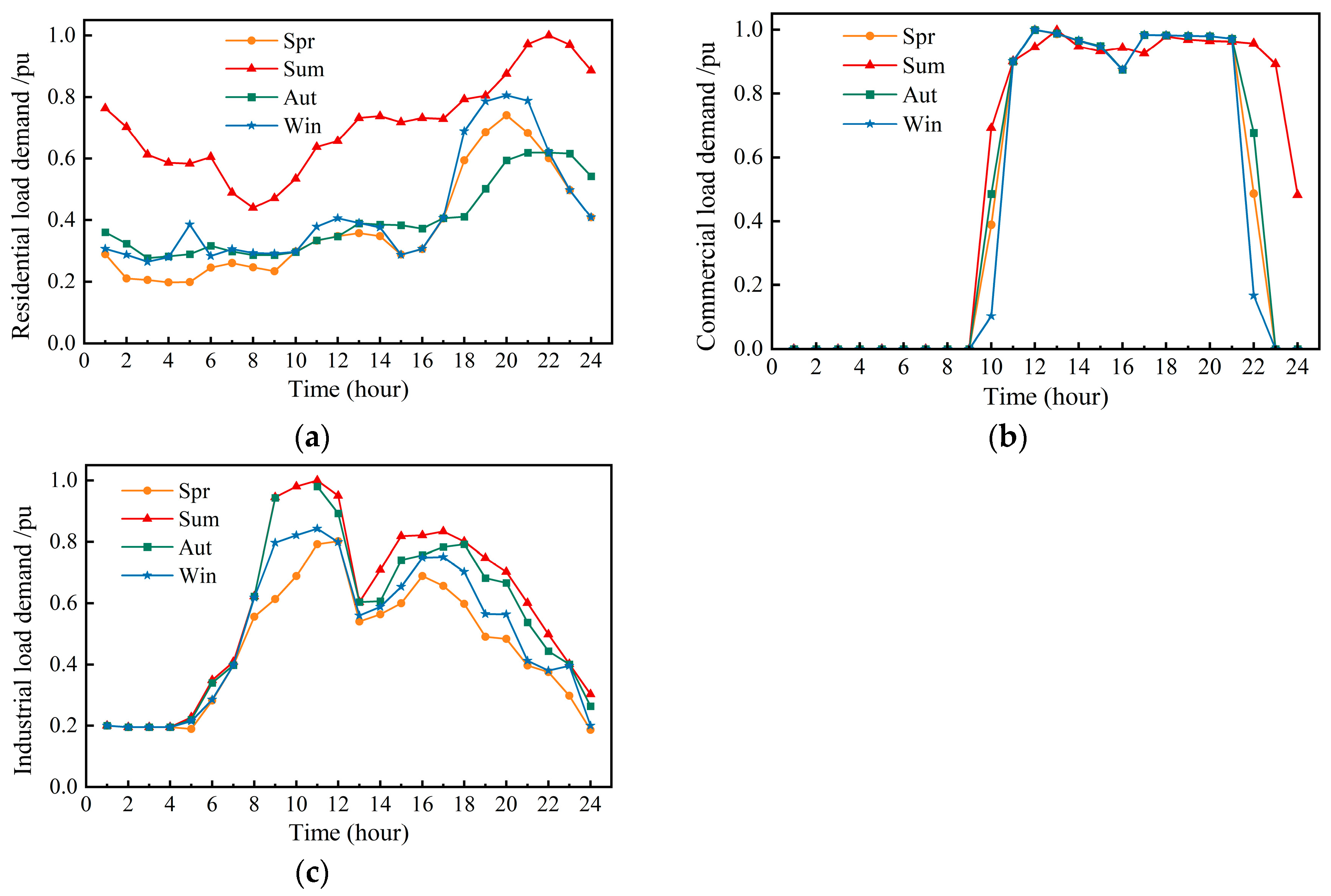
3.1. Load Temporal Characteristics

The classification of load types significantly impacts distribution network planning, as different load categories exhibit distinct power flow model properties, temporal characteristics, and demand response behaviors. This study focuses on three typical load types: residential, commercial, and industrial loads. In power flow modeling, load models are categorized into constant power (ZIP model), constant current, and constant impedance models. Each load type has unique static voltage-dependent power function representations, with practical implementations requiring differentiated modeling approaches. The equivalent load model is shown in Equation (1).
P l o a d = P 0 l o a d ( V V 0 ) α Q l o a d = Q 0 l o a d ( V V 0 ) β
In Equation (1), the parameters P 0 L o a d and Q 0 L o a d are the active and reactive power at the rated voltage (V0), and the parameters Pload and Qload are the active and reactive power considering static voltage characteristics, respectively. The parameters α and β represent the active and reactive voltage characteristic exponents, respectively. Table 1 provides reference values for these exponents across different seasons.
This study considers residential, commercial, and industrial loads as research objects, with their seasonal load curves shown in Figure 2. The analysis reveals significant temporal characteristic differences among various load types, while simultaneously demonstrating distinct seasonal patterns within the same load category. Specifically, residential loads reach their annual peak in summer, consistently exceeding the consumption levels of other seasons across all time periods. Commercial loads exhibit minimal seasonal variation in electricity consumption patterns. Although industrial loads show moderate seasonal differences in energy consumption, they maintain remarkably similar temporal fluctuation trends throughout different seasons.
Given the typically higher load stress during summer compared to other seasons. The evaluation of the distribution network’s load acceptance capability during summer high-temperature periods becomes particularly critical. This paper therefore investigates the network’s load acceptance capacity based on typical daily load profiles in summer.

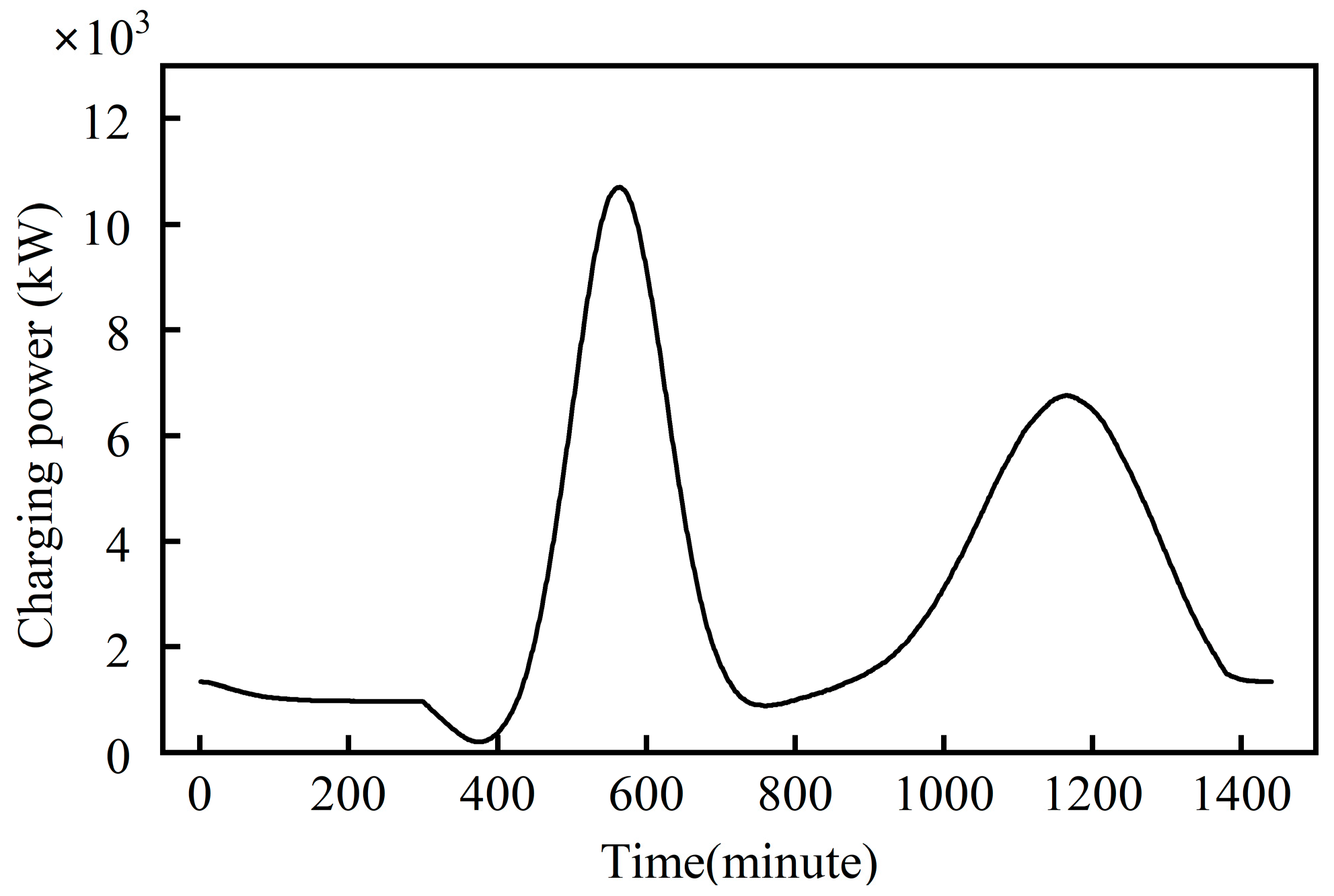
3.2. Electric Vehicle Charging Demand Model

The charging demand model for EVs requires the consideration of multiple factors. Prior to constructing such a model, it is essential to account for EV users’ charging behaviors, the actual charging demands of EVs, and the specific models of electric vehicles. Based on current EV usage patterns and existing research, the principle hypotheses in our study are as follows [26,27]:
(1)
EV charging behavior: single daily charge.
(2)
Each charging session achieves full battery replenishment.
(3)
Standard battery capacity is configured at 24 kwh.
The charging load characteristics are influenced by multiple factors, including vehicle type, charging time windows, daily travel mileage (following a log–normal distribution), and charging modes. Utilizing data from the U.S. Department of Transportation’s National Household Travel Survey [28], statistical normalization and maximum likelihood estimation methods confirm that daily travel mileage follows a log–normal distribution and the last trip return time adheres to a normal distribution [26], and the probability density function is expressed as Equation (2).
f D x = 1 3.2 x 2 π exp [ ( l n ( x ) 3.2 ) 2 2 · ( 0.8 ) 2 ]
The EV charging time follows a normal distribution, with its probability distribution characteristics detailed in Table 2.
To validate the proposed probabilistic distribution model for EV charging demand, Monte Carlo sampling with a cohort of 2000 EVs was implemented in our study, resulting in the charging power demand curve illustrated in Figure 3.

4. Active Distribution Network Multi-Form Load Acceptance Capacity Assessment Method

4.1. Acceptance Capacity Assessment Model

Distribution network acceptance capacity refers to the maximum permissible load that can be integrated while maintaining operational safety. Accurate evaluation of the capacity provides critical guidance for large-scale user load integration during service expansion. This study establishes multi-constraint conditions as limiting factors, including node voltage deviation constraints, overcurrent protection thresholds, and rated distribution capacity constraints, as shown in Equations (3) and (4).
U i m i n U i U i m a x ( i = 1 , 2 , , N ) I j I J m a x   j = 1 , 2 , , N l S t r S t r m a x t r = 1 , 2 , , N t r
P G , i P L , i = U t ν = 1 N U ν G i ν c o s θ i ν + B i ν s i n θ i ν Q G , i Q L , i = U t ν = 1 N U ν G i ν s i n θ i ν B i ν c o s θ i ν
In Equations (3) and (4), the parameters Ui, Uimax, and Uimin represent the voltage magnitude and voltage upper and lower limits at node i, respectively. The parameters Ij and Ijmax represent the current flow and maximum ampacity of branch j, respectively. The parameters Str and Strmax represent the power flow and maximum allowable capacity of the transformer branch, respectively. The parameters N, Nl, and Ntr represent the total quantities of nodes, branches, and transformers, respectively. The parameters PG,i and QG,i represent the active and reactive power injections at node i, respectively. The parameters PL,i and QL,i represent the active and reactive load demands at node i, respectively. The parameters Giv and Biv represent the conductance and susceptance between nodes i and v, respectively. The parameter θiv represents the voltage phase angle difference between nodes.

4.2. Load Growth Pattern

Large user service expansion applications may cause power flow exceedances in distribution networks. Therefore, when analyzing the maximum acceptable new load for grid acceptance capacity, it is essential to account for the growth of existing loads. Simulating and emulating the actual growth patterns of original loads enable more rational identification of primary bottlenecks restricting load integration. To characterize load growth states and mechanisms, this paper establishes a spatiotemporal correlation method to describe interdependencies among multi-node load increments, thereby highlighting both the regularity and uncertainty inherent to load growth. The proposed methodology employs time-series computation to analytically describe interactions between existing loads and newly integrated loads.
In practice, power supply areas can be divided into multiple zones with distinct characteristics based on practical requirements. Original loads are categorized into four types: industrial, commercial, residential, and charging loads. Historical natural growth rates for each load category are derived from historical data collected by the distribution network. Future load growth rates can be projected by integrating policy guidance and urban spatial development plans.
Considering the disparities in development rates between regions and industries, this paper categorizes load growth rates into three levels—high, medium, and low—while dividing the distribution network into K distinct sub-regions. For the K divided sub-regions, the predicted load growth values under three growth rates in sub-region k are denoted as Ph,k, Pm,k, and Pl,k (k = 1, 2, …, K), with corresponding probabilities ph,k, pm,k, and pl,k. Through discretization, the probability sequence ak (i)(i = 0, 1, …, N) for each sub-region can be derived, as shown in Equations (5) and (6):
U k = P k P ¯
a k ( i ) = p h , k    , i = P h , k / P ¯ p m , k    , i = P m , k / P ¯ p l , k     , i = P l , k / P ¯ 0 , o t h e r s
In Equations (5) and (6), the parameter [x] represents the greatest integer less than or equal to x. The parameter Uk represents the number of discretized values in sub-region k. The parameter P ¯ represents the discretization step size.
Considering the correlation of load growth among regions, the final total probability sequence x(i) is derived based on the probability sequence derivation principle. The expected value, EP, of total regional load growth is obtained by calculating the expectation of x(i), and the increased load is subsequently allocated according to the load distribution, as shown in Equations (7) and (8).
x i = a 1 i a 2 i a c i
E P = P ¯ i = 0 U 0 i x i
In Equations (7) and (8), the parameter U0 represents the sum of discretized values from sub-regions partitioned in the total region, and the symbol represents convolutional summation.
Taking into account the regional simultaneity factor ηng, the predicted value of total regional load growth, PForecast, can be determined as shown in Equation (9).
P Forecast = η ng × E P

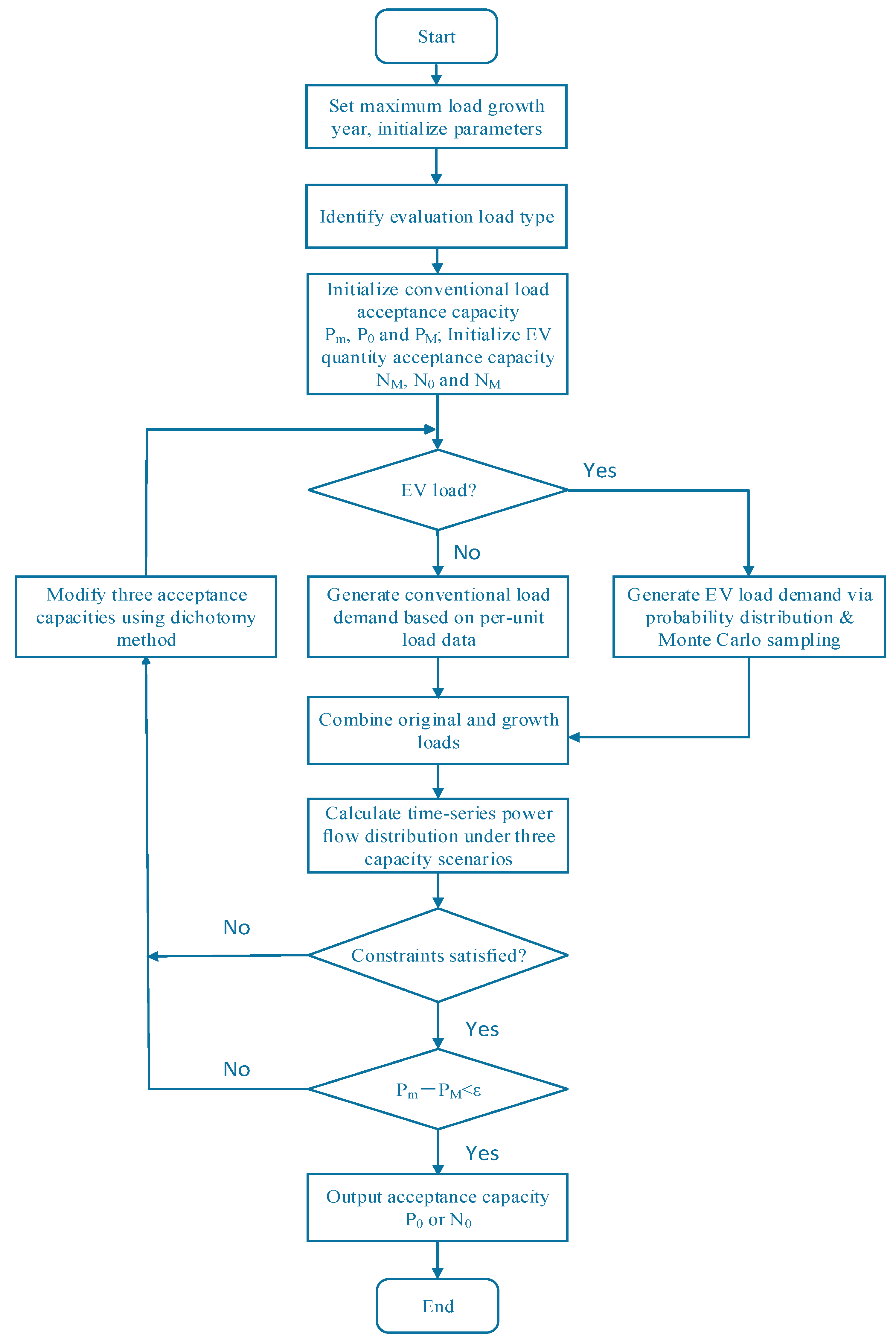
4.3. Multi-Form Load Acceptance Capacity Evaluation Process Based on Improved Repetitive Power Flow Method

The repetitive power flow method is a commonly used approach for determining the supply capacity under state variable constraints, which can be applied to evaluate the acceptance capacity of distribution networks for specific load types. In practical engineering applications, considering EV integration, load growth scenarios, and state variable constraints, engineers require not only supply capacity indicators but also need to assess the remaining supply potential of distribution network components under current load levels. This assessment guides the reliable integration of large consumers during load growth while maintaining the anticipated power flow conditions in distribution networks. To address this, this paper proposes a bisection-based repetitive power flow method for evaluating multi-modal load acceptance capacity, as illustrated in Figure 4.

5. Case Study

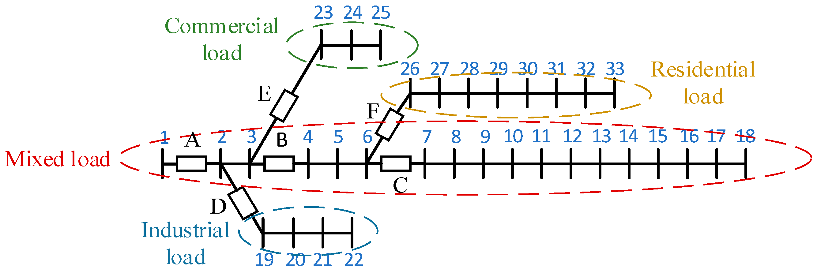
5.1. Case Study Introduction

This paper adopts the IEEE 33-node distribution system for case study analysis, employing a typical summer daily load profile from a city in southern China to simulate temporal load characteristics. The nodal system evaluation area is partitioned into four power supply sub-regions: Region 1 comprises mixed loads (residential, commercial, and industrial), Region 2 predominantly contains residential loads, Region 3 primarily consists of commercial loads, and Region 4 mainly incorporates industrial loads. Original load curves for each node are generated through the normalization of baseline nodal data. Overcurrent protection thresholds for devices A–F across regional branches, respectively, are configured as 458 A, 388 A, 355 A, 335 A, 362 A, and 228 A. The system topology diagram is illustrated in Figure 5.
The base voltage of the distribution lines is 12.66 kV, with the lower voltage limit of nodes set to 0.93 pu. Power flow calculations are implemented in MATLAB R2021b using the forward–backward sweep method, with the convergence accuracy, ε1, set to 0.01. The initial loads correspond to the baseline system conditions, where zero-load nodes are initialized with 50 kW during load growth phases. For computational simplification, initial loads are normalized to 0.95 times, representing the maximum load observed during peak hours of typical daily operation. Natural growth rates are categorized into high, medium, and low scenarios based on regional load types and historical growth patterns, as specified in Table 3.
The initial load growth forecasted values are generated based on the load growth pattern. The probabilistic sequences a1(i), a2(i), a3(i), and a4(i) for each sub-region are derived through discretization of the initial growth forecast results. These sequences facilitate the calculation of the expected total load growth per region, ultimately determining nodal load increments through initial load distribution patterns.

5.2. Evaluation of Multi-Form Load Acceptance Capacity in Distribution Networks Without DG Integration

To validate the acceptance capacity evaluation methodology proposed in this paper, which incorporates load growth patterns and an improved repetitive power flow method, this study implements five incremental growth steps based on initial load conditions, resulting in six distinct distribution network load sets for computational analysis. For each load configuration, the nodal acceptance capacities for residential, commercial, and industrial loads and EVs were systematically calculated under DG-free operating conditions. The acceptance capacity results for residential, commercial, and industrial loads and EVs are given in Appendix A (Figure A1). Figure 6 illustrates the degradation rates of load acceptance capacity over a five-year load growth period.
From the acceptance capacity calculation results, the distribution network’s acceptance capacity exhibits attenuation characteristics from the source to the terminal nodes. For conventional load types, source nodes demonstrate a higher residential load acceptance capacity (89.07%), while terminal nodes show superior industrial load acceptance performance (87.73%). The network exhibits marginally better stability in industrial load accommodation compared to other load types.
Figure 6 reveals consistent attenuation trends for residential, commercial, and EV loads over the five-year period, with source-proximate nodes displaying weaker resistance to load growth impacts. Industrial load acceptance demonstrates superior anti-degradation characteristics, maintaining an annual attenuation rate of approximately 2% within viable nodal regions.

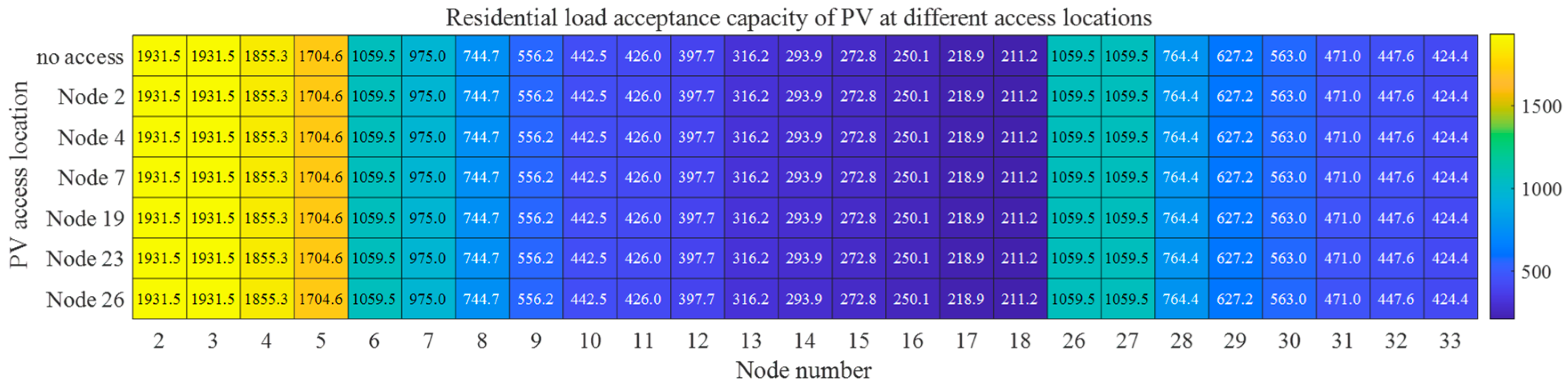
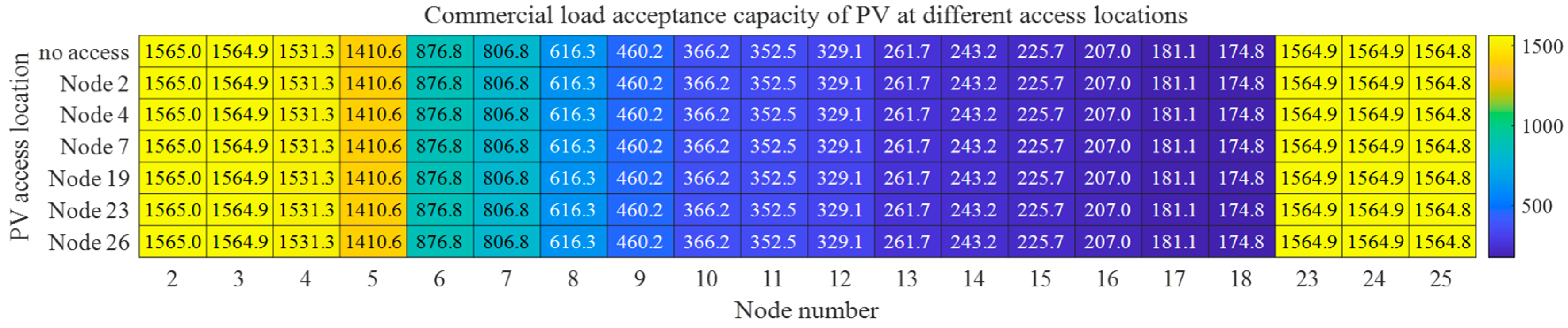
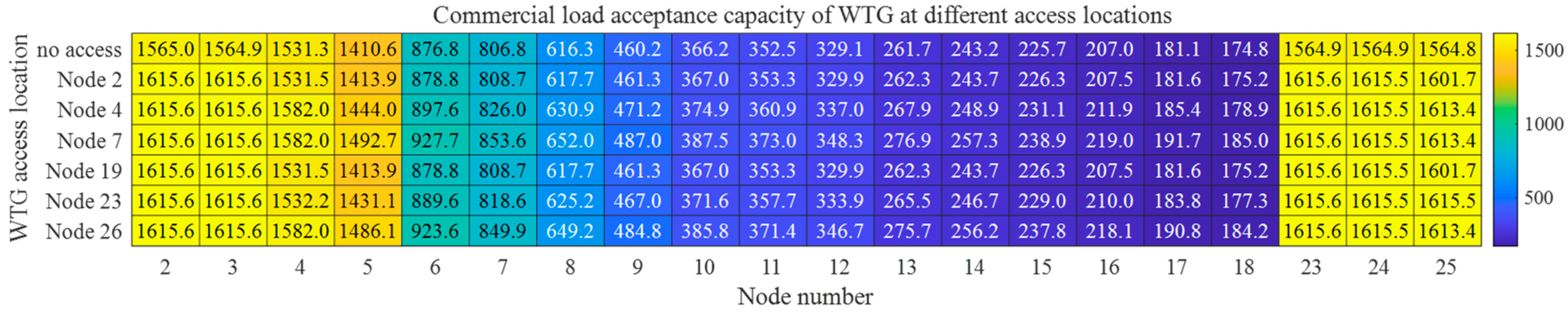
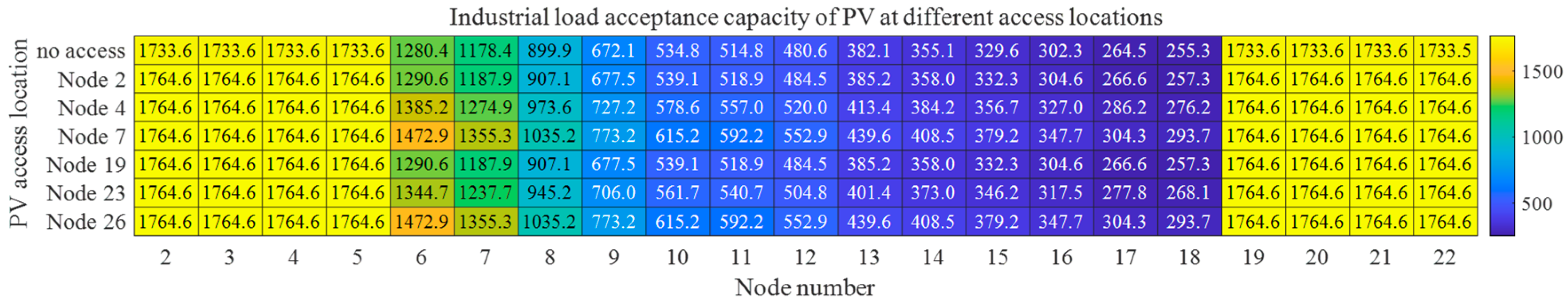
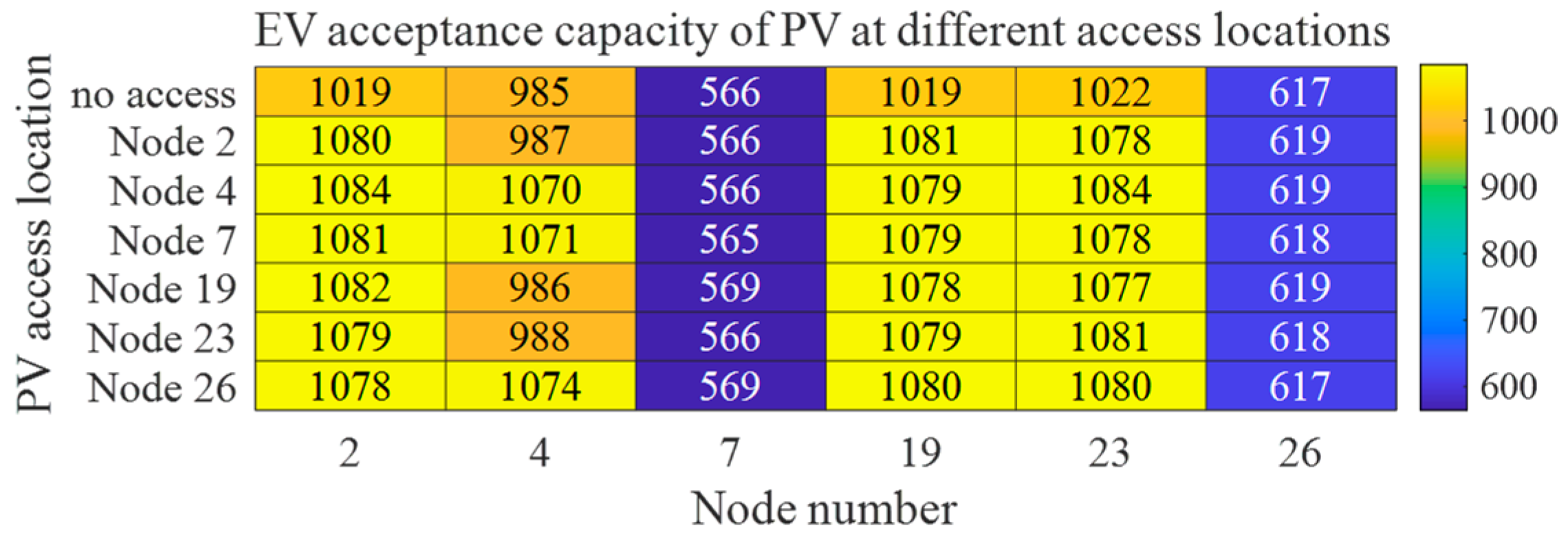
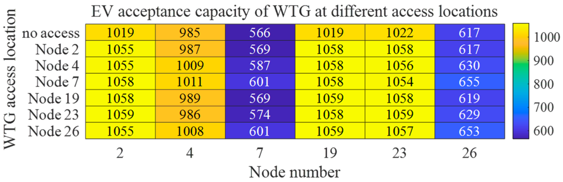
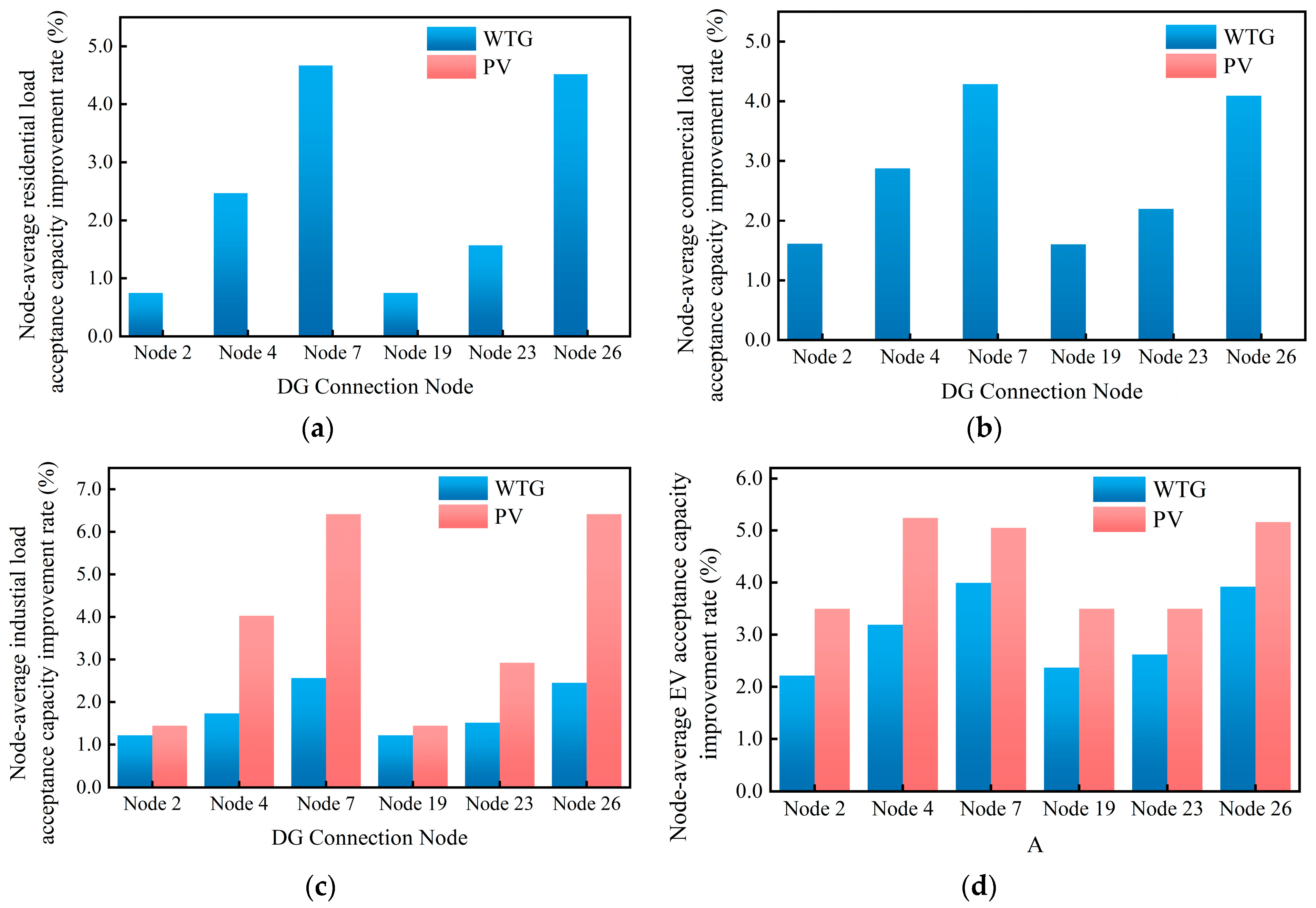
5.3. Impact of WTG and PV Integration Locations on Acceptance Capacity of Active Distribution Network

To evaluate the impact of DG access locations on the acceptance capacity of different load types, the case study was configured with a DG penetration capacity of 400 kW. After preliminary simulations revealed that the outcomes exhibited minimal variation when DG was connected to different nodes within the overcurrent protection device sub-regions, this section’s computational model strategically selected the directly connected sub-nodes of each overcurrent protection device as representative nodes to enhance computational efficiency. Separate simulations conducted for WTG and PV integration, with the acceptance capacity calculation results, are shown in Figure A2, Figure A3, Figure A4, Figure A5, Figure A6, Figure A7, Figure A8 and Figure A9 in Appendix B. And Figure 7 shows the node-average acceptance capacity improvement rate with and without DG integration for different load types.
Figure 7a demonstrates negligible PV location impacts on residential load acceptance capacity due to the temporal mismatch between residential demand patterns and PV output characteristics without energy storage. WTG integration at nodes 7 and 26 achieves maximum residential load acceptance improvements of 4.67% and 4.52%, respectively, while nodes 2 and 19 yield minimal enhancements (0.75%).
Figure 7b reveals similar location insensitivity for commercial load acceptance under PV integration. WTG integration at nodes 7 and 26 provides maximum commercial load acceptance improvements of 4.29% and 4.10%, with nodes 2 and 19 showing minimal gains (1.62% and 1.61%).
Figure 7c illustrates PV integration’s effects on industrial load acceptance. Maximum industrial load acceptance improvements (6.42%) occur when PV systems connect to nodes 7 and 26, while nodes 2 and 19 yield minimal enhancements (1.44%). WTG integration at nodes 7 and 26 achieves industrial load acceptance improvements of 2.56% and 2.45%, respectively, with node 2 showing the lowest enhancement (1.21%).
Figure 7d indicates that both PV and WTG integrations improve EV acceptance capacity. PV integration at node 4 achieves the maximum EV acceptance improvement (5.24%), followed by nodes 26 (5.16%) and 7 (5.05%). Regionally, node 19 demonstrates superior EV acceptance performance near nodes 7 and 26. WTG integration at node 7 provides maximum EV acceptance improvement (3.99%), with nodes 26 and 4 following at 3.92% and 3.19%.
In conclusion, mid-network DG integration (nodes 7 and 26) maximizes acceptance capacity improvements across all four load types, with industrial loads showing the greatest enhancement and commercial loads the least.

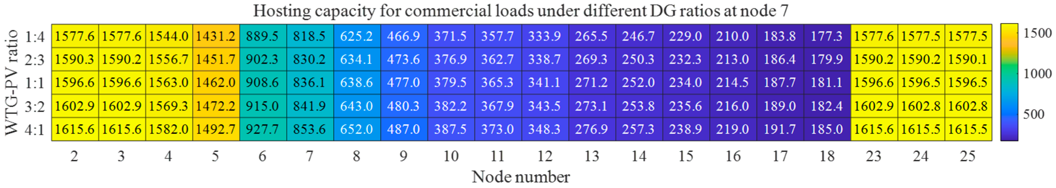
5.4. Impact of WTG-PV Ratio Variations on Acceptance Capacity

This section evaluates how WTG-PV ratio variations affect multi-form load acceptance capacities under 500 kW total DG integration. Five WTG-PV ratio scenarios (1:4, 2:3, 1:1, 3:2, 4:1) are analyzed using node 7 from Section 4.3 as a representative node. Figure A10, Figure A11, Figure A12 and Figure A13 show the calculation results of the acceptance capacity under different DG ratio scenarios in Appendix C. And Figure 8 shows the improvement rate of different load acceptance capacities under five WTG-PV ratio scenarios.
Figure 8a demonstrates increasing residential load acceptance capacity with higher WTG-PV ratios. Source nodes 2–4 show a 2.78% improvement differential between extreme ratios (4:1 vs. 1:4), while nodes 5–18 and 26–27 exhibit maximum differentials of 4.52%. Nodes with higher residential load proportions display more pronounced ratio sensitivity.
Figure 8b shows that the commercial load acceptance capacity has the same trend as in Figure 8a, showing residential load acceptance capacity as the change in WTG-PV ratio, with maximum improvement differentials of 4.48% between extreme ratios. Nodes with higher commercial load proportions show reduced improvement rates.
Figure 8c indicates minimal WTG-PV ratio sensitivity for industrial load acceptance at network extremities, with the overall capacity decreasing as WTG-PV ratios increase. The 4:1 ratio shows a 9% maximum reduction compared to the 1:4 ratio. Current constraints rather than voltage limitations dominate industrial load acceptance bottlenecks.
Figure 8d demonstrates mixed EV acceptance responses, and nodes 2, 4, 19, and 23 show decreasing EV accommodation with higher WTG-PV ratios, while other nodes exhibit opposite trends. The maximum differentials reach 7.6% at node 4 (4:1 ratio) and 1.4% at node 18 (1:1 ratio).
In summary, for residential and commercial loads, the acceptance capacity increases with the increasing WTG-PV ratio, where WTG dominates the enhancement of acceptance capacity for both, while industrial load exhibits an opposite trend primarily governed by PV. For EVs, the hosting capacities at different nodes demonstrate complex relationships with the DG ratio.

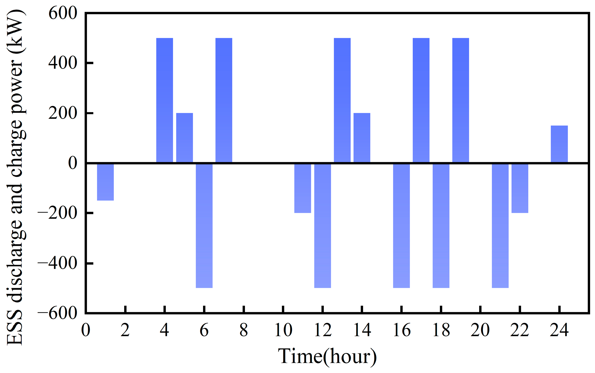
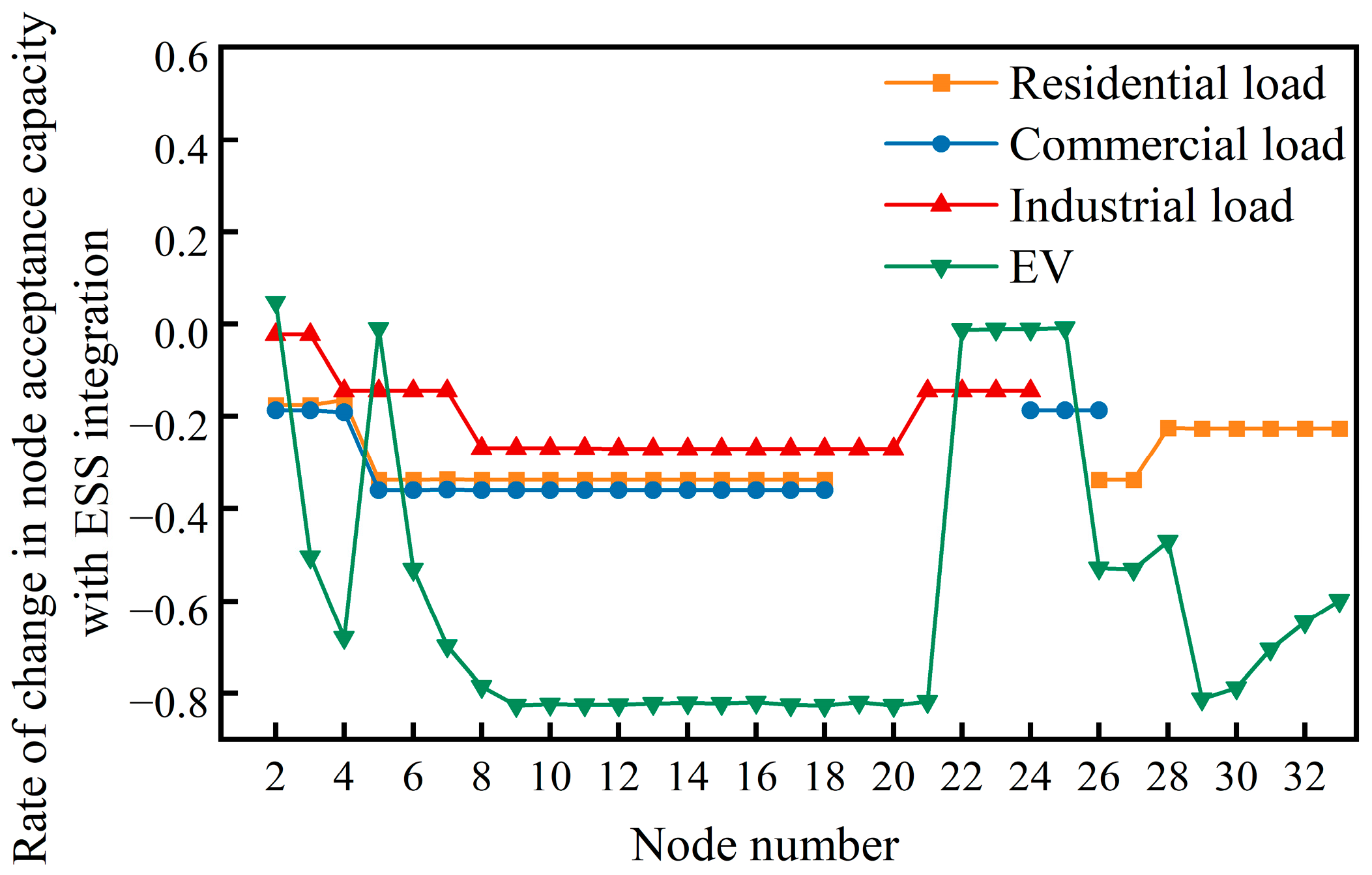
5.5. Impact of ESS Access on Acceptance Capacity of Active Distribution Network

This section evaluates the distribution network’s acceptance capacity for various loads under user-side ESS integration. In practical engineering scenarios, a user-side ESS operates to meet load demands through charging during valley load periods and discharging during peak load periods [29]. This study configures a user-side ESS with a maximum charging/discharging power of 500 kW and a maximum storage capacity of 1 MW at node 7 of the IEEE 33-bus system. To obtain the ESS charging/discharging power profile, this paper establishes an optimization model based on the charge and discharge benefits of the ESS. The model is derived through a heuristic optimization algorithm, with the results presented in Figure 9. Comparative calculations reveal the variation rate of acceptance capacity after ESS integration, as illustrated in Figure 10.
Figure 10 demonstrates that the integration of energy storage systems (ESSs) reduces the distribution network’s acceptance capacity for four load types. The industrial load exhibits the minimal capacity reduction, ranging from 0 to 28%, followed by residential and commercial loads, with 18–38% reductions. Electric vehicle (EV) integration shows the most significant impact, where acceptance capacity reductions vary substantially across regional nodes—the maximum 78% reduction occurs in mixed-load areas versus the 5% minimum in industrial zones.
This section reveals that user-side ESSs in radial distribution networks exhibit disordered charging behaviors. To maintain energy balance across consecutive time intervals, ESS charging processes cause dramatic load increases at nodes, leading to sudden load rate surges and frequent voltage limit violations, ultimately diminishing the acceptance capacity.

6. Conclusions

This paper investigates an effective evaluation method for assessing distribution network load acceptance potential under load growth demands, proposing a novel assessment approach that incorporates actual load growth patterns. The principal conclusions are summarized as follows:
(1)
The adoption of growth patterns reflecting actual load variations enables more targeted identification of practical acceptance bottlenecks, yielding assessment results with enhanced practical applicability and guidance value for subsequent load expansion planning.
(2)
The improved repetitive power flow evaluation methodology integrates load growth demands, multi-type load integration, and a bisection algorithm for rapid computation. Compared with conventional methods, this approach demonstrates superior capability in maximizing distribution network acceptance capacity, with its effectiveness validated through comprehensive case studies.
(3)
The case study demonstrates the following: ① The analysis of influencing factors under DG integration reveals that five-year original load growth induces annual acceptance capacity degradation rates of 3–5%, while mid-network DG integration (central nodes) achieves up to 5% higher acceptance capacity differentials compared to peripheral nodes. ② Spatial heterogeneity exists in optimal DG allocation, where WTG at central nodes enhances the residential/commercial load acceptance capacity by 4.27–4.29%, while PV deployment at terminal nodes maximizes the industrial load acceptance capacity improvement up to 14.7%. PV integration at node 4 achieves 5.24% maximum EV load enhancement. ③ Optimal WTG-PV ratio configurations yield differentiated benefits: a 4:1 WTG-PV ratio improves the residential/commercial load acceptance capacity by 2.18%, whereas a 1:4 ratio enhances the industrial load capacity by 6.42%. For EVs, regions closer to DG access nodes demonstrate enhanced acceptance capacity with higher WTG-PV ratios, while conversely, regions farther from DG access nodes exhibit improved performance under lower WTG-PV ratio conditions. ④ Regarding the integration behavior of user-side ESSs, the distribution network experiences a decline in acceptance capacity for different types of loads. Particularly notable is the most significant reduction in EV acceptance capacity, with the maximum node reduction rate reaching 80%. In contrast, the impact on industrial load acceptance capacity remains relatively moderate, where the maximum node acceptance capacity reduction rate is 28%.
The proposed methodology provides essential decision-support tools for load expansion service planning and DG integration impact analysis, ultimately strengthening operational stability assurance for distribution networks.
In the assessment of distribution network load acceptance capacity, different load modeling methods affect power flow calculation results, thereby influencing the load acceptance capacity evaluation outcomes. Beyond the load generation approach adopted in this paper, uncertainty modeling in loads can be further introduced to evaluate the network’s acceptance capacity while ensuring operational robustness of the distribution network.

Author Contributions

Conceptualization, Z.K.; methodology, Y.H.; software, H.L.; validation, G.L. and H.L.; formal analysis, G.L.; investigation, H.L.; resources, H.L.; data curation, H.L.; writing—original draft preparation, Z.K. and H.L.; writing—review and editing, H.L. and Y.H.; visualization, G.L.; supervision, G.L.; project administration, G.L.; funding acquisition, Y.H. All authors have read and agreed to the published version of the manuscript.

Funding

This research is funded by China Southern Power Grid Corporation Science and Technology project, grant number 031900KC23120073.

Data Availability Statement

Data are contained within the article.

Conflicts of Interest

Authors Zhicong Kuang, Gang Liu, and Heting Lu were employed by the company Dongguan Power Supply Bureau of Guangdong Power Grid Co. The remaining authors declare that the research was conducted in the absence of any commercial or financial relationships that could be construed as potential conflicts of interest.

Appendix A

Figure A1. Distribution network acceptance capacity for residential, commercial, and industrial loads and EVs considering load growth. (a) Residential load acceptance capacity at each node; (b) commercial load acceptance capacity at each node; (c) industrial load acceptance capacity at each node; (d) EV acceptance capacity at each node.
Electronics 14 01566 g0a1

Appendix B

Figure A2. Residential load acceptance capacity of PV at different access locations.
Electronics 14 01566 g0a2
Figure A3. Residential load acceptance capacity of WTG at different access locations.
Electronics 14 01566 g0a3
Figure A4. Commercial load acceptance capacity of PV at different access locations.
Electronics 14 01566 g0a4
Figure A5. Commercial load acceptance capacity of WTG at different access locations.
Electronics 14 01566 g0a5
Figure A6. Industrial load acceptance capacity of PV at different access locations.
Electronics 14 01566 g0a6
Figure A7. Industrial load acceptance capacity of WTG at different access locations.
Electronics 14 01566 g0a7
Figure A8. EV acceptance capacity of PV at different access locations.
Electronics 14 01566 g0a8
Figure A9. EV acceptance capacity of WTG at different access locations.
Electronics 14 01566 g0a9

Appendix C

Figure A10. Acceptance capacity for residential loads under different DG ratios at node 7.
Electronics 14 01566 g0a10
Figure A11. Acceptance capacity for commercial loads under different DG ratios at node 7.
Electronics 14 01566 g0a11
Figure A12. Acceptance capacity for industrial loads under different DG ratios at node 7.
Electronics 14 01566 g0a12
Figure A13. Acceptance capacity for EV under different DG ratios at node 7.
Electronics 14 01566 g0a13

References

  1. Shafiullah; Ahmed, S.D.; Al-Sulaiman, F.A. Grid Integration Challenges and Solution Strategies for Solar PV Systems: A Review. IEEE Access 2022, 10, 52233–52257. [Google Scholar] [CrossRef]
  2. Rana, M.; Uddin, M.; Sarkar, R.; Meraj, S.T.; Shafiullah, G.; Muyeen, S.; Islam, A.; Jamal, T. Applications of energy storage systems in power grids with and without renewable energy integration—A comprehensive review. J. Energy Storage 2023, 68, 107811. [Google Scholar] [CrossRef]
  3. Kataray, T.; Nitesh, B.; Yarram, B.; Sinha, S.; Cuce, E.; Shaik, S.; Vigneshwaran, P.; Roy, A. Integration of smart grid with renewable energy sources: Opportunities and challenges—A comprehensive review. Sustain. Energy Technol. Assess. 2023, 58, 103363. [Google Scholar] [CrossRef]
  4. Yang, W.; Peng, H.; Chen, Y.; Zhu, L. Optimal site selection and capacity determination method for low-voltage distribution network industry expansion and installation. In Proceedings of the 2023 8th Asia Conference on Power and Electrical Engineering (ACPEE), Tianjin, China, 14–16 April 2023; pp. 2543–2548. [Google Scholar]
  5. Vahidinasab, V.; Tabarzadi, M.; Arasteh, H.; Alizadeh, M.I.; Beigi, M.M.; Sheikhzadeh, H.R.; Mehran, K.; Sepasian, M.S.; Mohammadbeygi, M. Overview of Electric Energy Distribution Networks Expansion Planning. IEEE Access 2020, 8, 34750–34769. [Google Scholar] [CrossRef]
  6. Yan, G.; Wang, Q.; Zhang, H.; Wang, L.; Wang, L.; Liao, C. Review on the Evaluation and Improvement Measures of the Carrying Capacity of Distributed Power Supply and Electric Vehicles Connected to the Grid. Energies 2024, 17, 4407. [Google Scholar] [CrossRef]
  7. Mahdavi, M.; Schmitt, K.E.K.; Jurado, F. Robust Distribution Network Reconfiguration in the Presence of Distributed Generation Under Uncertainty in Demand and Load Variations. IEEE Trans. Power Deliv. 2023, 38, 3480–3495. [Google Scholar] [CrossRef]
  8. Rodrigo, A.S.; Priyanka, V.G.C. Impact of High Penetration of EV Charging on Harmonics in Distribution Networks. In Proceedings of the 2018 Moratuwa Engineering Research Conference (MERCon), Moratuwa, Sri Lanka, 30 May–1 June 2018; pp. 340–344. [Google Scholar]
  9. Basnet, S.; Deschinkel, K.; Le Moyne, L.; Péra, M.C. A review on recent standalone and grid integrated hybrid renewable energy systems: System optimization and energy management strategies. Renew. Energy Focus 2023, 46, 103–125. [Google Scholar] [CrossRef]
  10. Chowdhury, S.; Bohre, A.K. Economic Assessment of PV Wind based HRES including Battery Storage and FC. In Proceedings of the 2023 IEEE International Conference on Power Electronics, Smart Grid, and Renewable Energy (PESGRE), Trivandrum, India, 17–20 December 2023; pp. 1–6. [Google Scholar]
  11. Khan, A.A.; Minai, A.F.; Pachauri, R.K.; Malik, H. Optimal Sizing, Control, and Management Strategies for Hybrid Renewable Energy Systems: A Comprehensive Review. Energies 2022, 15, 6249. [Google Scholar] [CrossRef]
  12. Hua, Y.-P.; Wang, S.-Q.; Han, D.; Bai, H.-K.; Wang, Y.-Y.; Li, Q.-Y. Analysis of Charging Load Acceptance Capacity of Electric Vehicles in the Residential Distribution Network. World Electr. Veh. J. 2022, 13, 214. [Google Scholar] [CrossRef]
  13. Ji, Y.; Zhang, J.; Li, S.; Deng, Y.; Mu, Y. Electric vehicles acceptance capacity evaluation in distribution network considering photovoltaics access. Energy Rep. 2023, 9, 602–608. [Google Scholar] [CrossRef]
  14. Li, X.; Liu, Y.; Liang, Y.; Zeng, S.; Li, M. Evaluation and optimization of Electric Vehicle Load Acceptance Capacity of Distribution Network. In Proceedings of the 2020 IEEE 4th Conference on Energy Internet and Energy System Integration (EI2), Wuhan, China, 30 October–1 November 2020; pp. 1890–1895. [Google Scholar]
  15. Huang, Y.; Zhao, L.; Qiu, W.; Xu, Y.; Gao, J.; Yan, Y.; Wu, T.; Lin, Z. Evaluation of Acceptance Capacity of Distributed Generation in Distribution Network Considering Carbon Emission. Energies 2022, 15, 4406. [Google Scholar] [CrossRef]
  16. He, Y.B.; Ren, D.H.; Qin, T.; Cui, H.W. Power grid optimization planning based on DG acceptance capability evaluation of hybrid AC/DC transmission system. In Proceedings of the 16th IET International Conference on AC and DC Power Transmission (ACDC 2020), Online Conference, 2–3 July 2020; pp. 404–411. [Google Scholar]
  17. Yang, X.; Long, C.; Ye, Y.; Li, T.; Liu, L.; Wei, J.; Liu, X.; Bai, H. Distribution Network PV Acceptance Capacity Assessment Considering Balance of Flexibility Supply and Demand. In Proceedings of the 2022 Asian Conference on Frontiers of Power and Energy (ACFPE), Chengdu, China, 21–23 October 2022; pp. 592–599. [Google Scholar]
  18. Wu, H.; Yuan, Y.; Zhu, J.; Qian, K.; Xu, Y. Potential Assessment of Spatial Correlation to Improve Maximum Distributed PV Acceptance capacity of Distribution Networks. Mod. Power Syst. Clean Energy 2021, 9, 800–810. [Google Scholar] [CrossRef]
  19. Zhang, M.; Sun, Q.; Yang, X. Research on the assessment of the capacity of urban distribution networks to accept electric vehicles based on the improved TOPSIS method. IET Gener. Transm. Distrib. 2021, 15, 2804–2818. [Google Scholar] [CrossRef]
  20. Bajaj, M.; Singh, A.K. Grid integrated renewable DG systems: A review of power quality challenges and state-of-the-art mitigation techniques. Int. J. Energy Res. 2020, 44, 26–69. [Google Scholar] [CrossRef]
  21. Meinecke, S.; Sarajlić, D.; Drauz, S.R.; Klettke, A.; Lauven, L.-P.; Rehtanz, C.; Moser, A.; Braun, M. A Benchmark Dataset of Electric Power Systems to Compare Innovative Solutions Based on Power Flow Analysis. Energies 2020, 13, 3290. [Google Scholar] [CrossRef]
  22. Ray, P.; Ray, P.K.; Dash, S.K. Power Quality Enhancement and Power Flow Analysis of a PV Integrated UPQC System in a Distribution Network. IEEE Trans. Ind. Appl. 2022, 58, 201–211. [Google Scholar] [CrossRef]
  23. Kenedy, M.; Naresh, R.; Chauhan, R. An efficient Repeated Power Flow approach to evaluate Available Transfer Capability considering power systems security. In Proceedings of the 2023 Second International Conference on Electrical. Electronics, Information and Communication Technologies (ICEEICT), Trichirappalli, India, 5–7 April 2023; pp. 1–5. [Google Scholar]
  24. Elgamal, M.; Korovkin, N.; Menaem, A.A.; Elmitwally, A. An algorithm for power flow analysis in isolated hybrid energy microgrid considering DG droop model and virtual impedance control loop. Sustain. Energy Grids Netw. 2022, 32, 100875. [Google Scholar] [CrossRef]
  25. Papadimitrakis, M.; Giamarelos, N.; Stogiannos, M.; Zois, E.; Livanos, N.-I.; Alexandridis, A. Metaheuristic search in smart grid: A review with emphasis on planning, scheduling and power flow optimization applications. Renew. Sustain. Energy Rev. 2021, 145, 111072. [Google Scholar] [CrossRef]
  26. Yang, J.X.; Zhang, Y.J. Optimization of charging load acceptance capacity based on ordered charging start-up mechanism and subsidy mechanism. Electr. Power Autom. Equip. 2020, 40, 122–130. [Google Scholar]
  27. Luo, Q.; Huang, M.X. Probabilistic load flow calculation and accommodated capacity analysis for distribution grid containing electric vehicle. J. Mech. Electr. Eng. 2015, 32, 1498–1503. [Google Scholar]
  28. Zhang, J.; Yan, J.; Liu, Y.; Zhang, H.; Lv, G. Daily electric vehicle charging load profiles considering demographics of vehicle users. Appl. Energy 2020, 274, 115063. [Google Scholar] [CrossRef]
  29. Yang, H.; Chen, Q.; Liu, Y.; Ma, Y.; Zhang, D. Demand response strategy of user-side energy storage system and its application to reliability improvement. J. Energy Storage 2024, 92, 112150. [Google Scholar] [CrossRef]
Figure 1. Per-unit value of DG output. (a) WTG output per-unit value; (b) PV output per-unit value.
Electronics 14 01566 g001
Figure 2. Different types of load demand. (a) Residential load demand; (b) commercial load demand; (c) industrial load demand.
Electronics 14 01566 g002
Figure 3. Charging power demand curve of 2000 EVs.
Electronics 14 01566 g003
Figure 4. Multi-form load acceptance capacity assessment process for active distribution networks based on improved repeated power flow method.
Electronics 14 01566 g004
Figure 5. IEEE 33-node system topology diagram.
Electronics 14 01566 g005
Figure 6. Annual decline rate of distribution network acceptance capacity for different load types.
Electronics 14 01566 g006
Figure 7. Node-average acceptance capacity improvement rate for different load types. (a) Node-average residential load acceptance capacity improvement rate; (b) node-average commercial load acceptance capacity improvement rate; (c) node-average industrial load acceptance capacity improvement rate; (d) node-average EV acceptance capacity improvement rate.
Electronics 14 01566 g007
Figure 8. Acceptance capacity improvement rate for different types of loads under five WTG-PV ratio scenarios. (a) Residential load acceptance capacity improvement rate; (b) commercial load acceptance capacity improvement rate; (c) industrial load acceptance capacity improvement rate; (d) EV acceptance capacity improvement rate.
Electronics 14 01566 g008
Figure 9. ESS output power.
Electronics 14 01566 g009
Figure 10. EV acceptance capacity variation rate.
Electronics 14 01566 g010
Table 1. Characteristic values of load voltage in different seasons.
SeasonResidential LoadCommercial LoadIndustrial Load
αβαβαβ
Spring1.24.381.253.350.186.00
Summer0.722.961.253.500.186.00
Autumn0.983.520.993.950.186.00
Winter1.044.191.503.150.186.00
Table 2. Probability distribution of EV users’ travel and charging behavior.
Charging TimeDaily Travel Distance
N (9, 0.882)
N (19, 0.882)
U (23, 5)
ln l ~ N (3.2, 0.82)
Table 3. Regional load growth patterns.
PartitionMedium PlanHigh PlanLow Plan
Growth RateProbabilityGrowth RateProbabilityGrowth RateProbability
10.0500.510.0650.260.040.23
20.0400.550.0450.220.020.23
30.0600.540.080.270.0460.19
40.0980.570.1150.210.0760.22
Disclaimer/Publisher’s Note: The statements, opinions and data contained in all publications are solely those of the individual author(s) and contributor(s) and not of MDPI and/or the editor(s). MDPI and/or the editor(s) disclaim responsibility for any injury to people or property resulting from any ideas, methods, instructions or products referred to in the content.

