Article

A Low-Cost, Wide-Band, High-Gain Mechanically Reconfigurable Multi-Polarization Antenna Based on a 3-D Printed Polarizer

1
The Jianghuai Advance Technology Center, Hefei 230000, China
2
The Key Laboratory of Intelligent Computing and Signal Processing, Ministry of Education, Anhui University, Hefei 230601, China
3
Information Materials and Intelligent Sensing Laboratory of Anhui Province, Anhui University, Hefei 230601, China
4
The Key Laboratory of Electromagnetic Environmental Sensing of Anhui Higher Education Institutes, Anhui University, Hefei 230601, China
*
Author to whom correspondence should be addressed.
Electronics 2025, 14(6), 1224; https://doi.org/10.3390/electronics14061224
Submission received: 11 February 2025 / Revised: 28 February 2025 / Accepted: 14 March 2025 / Published: 20 March 2025

Abstract

:
This paper proposes a mechanically reconfigurable multi-polarization antenna based on a 3D-printed anisotropic dielectric polarizer, offering wide bandwidth, high gain, and extremely low cost. The working mechanism of the dielectric polarizer is analyzed, demonstrating its ability to efficiently convert linear polarization (LP) to circular polarization (CP) over a wide frequency range. Furthermore, the polarizer exhibits subwavelength characteristics. For a given duty cycle, its phase response depends only on the height and is independent of the aperture size. This property enables miniaturized and customized designs of the polarizer’s aperture size. Subsequently, the polarizer is placed above a Ku band waveguide and standard horn antennas. The results show that by rotating the dielectric polarizer and adjusting the positions of the antennas, right-handed CP (RHCP), left-handed CP (LHCP), and dual LP radiation switching can be achieved in the 12.4–18.0 GHz band, verifying the quad-polarization reconfigurability. Additionally, the polarizer significantly enhances the gain of the waveguide antenna by approximately 9.5 dB. Furthermore, due to the low-cost 3D printing material, the manufacturing cost of the polarizer is exceptionally low, making it suitable for applications such as anechoic chamber measurements and wireless communications. Finally, the measurement results further validate the accuracy of the simulations.

1. Introduction

Polarization is a fundamental characteristic of electromagnetic waves. It mainly includes four polarization states: left-hand circular polarization (LHCP), right-hand circular polarization (RHCP), vertical polarization (VP), and horizontal polarization (HP). A quad-polarization reconfigurable antenna can receive waves of any polarization, thus avoiding polarization mismatch and suppressing multipath interference, and improving communication quality and system capacity [1,2]. Such antennas can be widely used in satellite communication systems, wireless local area networks, and other applications.
Currently, research on quad-polarization reconfigurable antennas has attracted the attention of researchers. These antennas primarily achieve polarization switching through active devices that control the radiation patches or feeding networks [3,4,5,6,7,8,9,10,11,12,13,14,15,16]. For example, in [3], a feeding network reconfigurable antenna is proposed, where the phase difference required to generate the four polarization modes is achieved by switching the state of PIN diodes on the feeding network, enabling quad-polarization switching. However, the bandwidth is narrow. In [8], quad-polarization switching is achieved by integrating crossed dipole feeding and adding reconfigurable branches to a magnetoelectric dipole patch. The antenna surface current distribution is controlled by simply changing the diode states, eliminating the need for a complex network. However, the operating bandwidth is still relatively narrow. Additionally, most of these designs have large apertures, making it difficult to form arrays. On the other hand, quad-polarization achieved through antennas or metasurfaces is limited by the inherent half-wavelength resonance constraint of their unit, making miniaturization and size customization challenging [3,4,5,6,7,8,9,10,11,12,13,14,15,16,17,18]. On the other hand, anisotropic dielectric polarizers based on 3D printing technology have attracted widespread attention due to their low cost, wide bandwidth, and simple structure [19,20,21,22,23]. For example, Castro et al. proposed a 3D-printed anisotropic dielectric polarizer, which demonstrated the potential application of 3D printing technology in the millimeter-wave frequency band [24]. Similarly, Melendro-Jiménez et al. introduced a novel logarithmic spiral 3D-printed dielectric polarizer for dual circular polarization conical beam radiation patterns in the Ka band [25]. Currently, most research on dielectric polarizer primarily focuses on the conversion from LP to CP, while studies on multi-polarization mechanically reconfigurable antennas based on dielectric polarizers remain scarce.
This paper presents a low-cost, wideband, high-gain mechanically reconfigurable multi-polarization antenna design based on an anisotropic dielectric polarization converter. First, the working mechanism of the polarizer unit is described in detail, revealing that the polarizer can convert LP waves to CP waves over a wideband range. In addition, the dielectric polarizer exhibits subwavelength characteristics, where its phase response is only related to the height and is independent of the aperture size. Based on this property, the aperture size of the dielectric polarizer can be miniaturized and customized without significantly affecting its operating frequency range or polarization conversion performance. Then, to verify the performance, the dielectric polarization converter is applied to the standard-gain horn antenna and waveguide antenna in the Ku band. Simulation results show that by adjusting the rotation of the dielectric polarizer and the orientation of the horn antenna and waveguide antenna, quad-polarization switching among RHCP, LHCP, and dual LP can be achieved within a wide bandwidth range of 12.4–18 GHz. Finally, the measurement results validate the accuracy of the simulation.

2. Design of Dielectric Polarization Converter Unit

This section introduces the design of the dielectric polarization unit, demonstrating that the dielectric polarizer has the ability to convert LP waves into CP waves within a wide frequency band. The operating principle of the dielectric polarizer unit are discussed in detail, providing a solid foundation for subsequent integration with the horn and waveguide antenna.

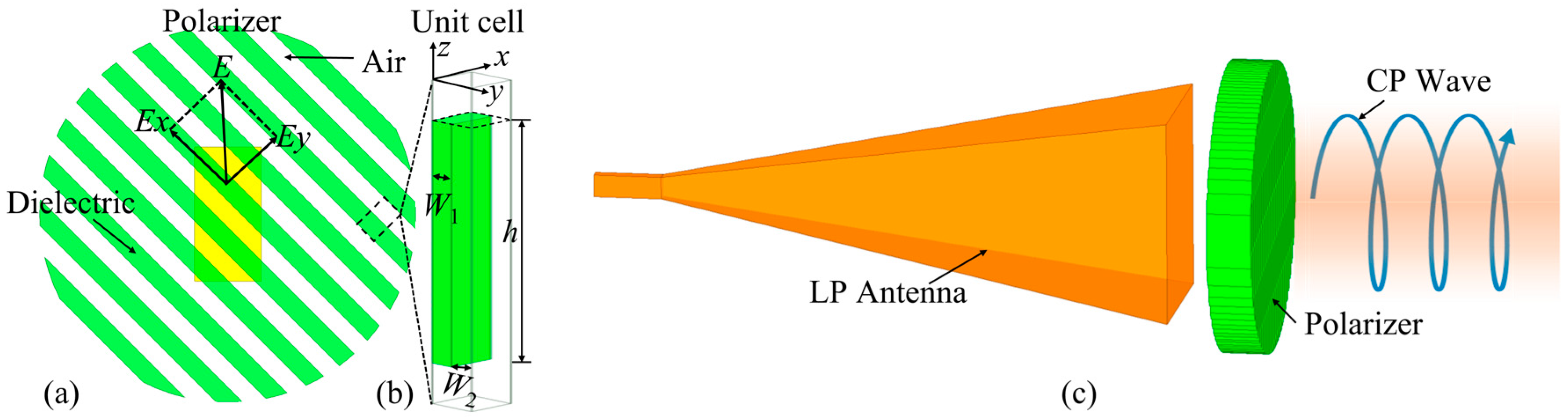
2.1. Working Principle

To achieve LP to CP conversion over a wide bandwidth, it is necessary to ensure that the magnitudes of the electric field components in the horizontal direction (Ex) and vertical direction (Ey) are approximately equal, and the phase difference (PD) between them is approximately 90°. As shown in Figure 1, when an LP plane wave impinges at a 45° angle on the anisotropic dielectric polarization converter, the incident wave can be decomposed into two mutually perpendicular components: Ex and Ey. Due to the anisotropy of the material, the effective dielectric constants in the x and y directions are different, resulting in different propagation speeds for the electromagnetic waves in the x and y directions. By adjusting the height h of the dielectric polarizer, a desired 90° PD can be achieved. Additionally, if dielectric losses are neglected, the magnitudes of Ex and Ey can be made approximately equal over a wide bandwidth. This results in an efficient conversion from an LP to a CP wave.

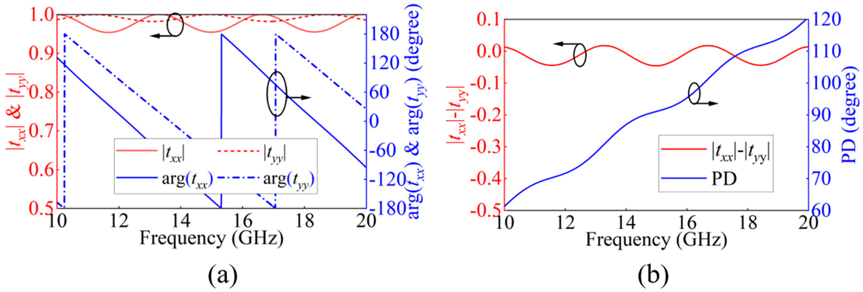
2.2. Dielectric Polarizer Unit Design

The dielectric polarizer is fabricated using 3D printing technology, with the material chosen being low-cost polylactic acid (PLA) with a dielectric constant of 2.72 to ensure cost-effectiveness. Figure 1b illustrates the structure of the dielectric polarizer unit, which consists of a PLA dielectric and an air layer, with widths denoted as W1 and W2, respectively. The duty cycle q is defined as the ratio of q = W1/(W1 + W2). When a linearly polarized plane wave impinges on the polarizer at a 45° angle, the incident wave can be decomposed into components along the x-direction (parallel to the grating strips) and the y-direction (perpendicular to the grating strips). Due to the material’s anisotropy, the effective dielectric constants in the x and y directions are different. By calculating their volumetric average, the effective dielectric constants in the x and y directions can be expressed as [26,27,28]:
ε x = 1 + q ( ε r 1 )
ε y = 1 q ε r + ( 1 q )
In the above equation, ε r represents the dielectric constant of the material. The dielectric constants in the x and y directions, denoted as ε x and ε y , respectively, are not equal due to the anisotropic nature of the material. This anisotropy allows for the manipulation of the PD between the electric field components E x and E y by adjusting the height h of the dielectric polarizer.
To achieve a specific phase difference, such as a 90° PD between E x and E y , the height h of the dielectric polarizer can be approximated using the following formula:
h λ 0 4 | ε x ε y |
Here, λ 0 is the wavelength of the incident wave in free space. To achieve the target frequency band of 12.4–18.0 GHz for the Ku band standard-gain horn antenna and waveguide, the height h of the polarizer is calculated to be approximately 33 mm, with W1 = W2 = 0.5 mm, based on Equation (3). Subsequently, the polarizer unit is modeled and simulated in CST Microwave Studio simulation 2022 software. The simulated transmission coefficients txx and tyy in the x and y directions, as well as the phases arg(txx) and arg(tyy), are shown in Figure 2a. Figure 2b displays the simulation results for the amplitude difference and PD. It can be observed that, over the 12.4–18.0 GHz band, the amplitude difference is close to 0, while the phase difference is approximately 90° ± 20°. These results demonstrate that the polarizer can efficiently perform LP to CP conversion across a wide bandwidth. On the other hand, from Equations (1)–(3), it is clear that the phase response of the dielectric polarizer depends solely on the duty cycle and height, and is independent of the aperture size, which exhibits subwavelength characteristics. Based on this feature, the aperture size of the polarizer can be miniaturized and customized.

3. Multi-Polarization Reconfigurable Antenna Based on Dielectric Polarizer

It is elaborated that loading a low-cost dielectric polarizer can convert the LP of horn and waveguide antennas into CP. By mechanically adjusting the relative position of the polarizer with respect to the waveguide (or horn) antenna, reconfigurable four-polarization states can be achieved.

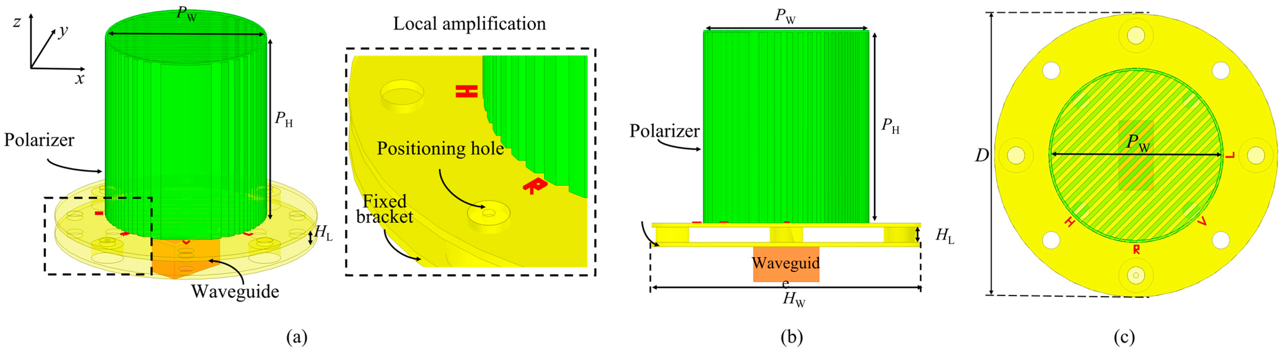
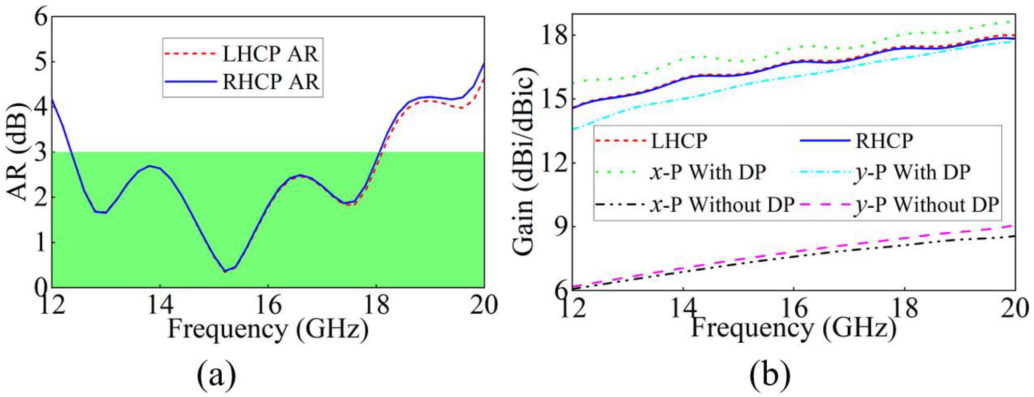
3.1. Waveguide Antenna with a Dielectric Polarizer

Figure 3 shows the structure of the integration of the dielectric polarizer with the Ku band waveguide antenna. The structure consists of three main components: at the bottom, the waveguide; in the middle, a fixed bracket used to secure the waveguide and polarizer; and at the top, the dielectric polarizer. The middle fixed bracket is designed with a positioning hole and several through-holes to facilitate precise installation. The base of the polarizer structure is marked with the symbols R, L, H, and V. When the hole is on the R (L) side, RHCP (LHCP) polarization is achieved. When the hole on the H or V side is aligned with the positioning hole, polarization conversion does not occur. However, the dual linear polarization (LP) characteristics of the waveguide can be utilized, and by adjusting the position of the waveguide, dual LP reconfigurability can be achieved. This allows the entire design to achieve mechanically reconfigurable quad-polarization switching.
To verify the above analysis, a simulation of the waveguide with and without the dielectric polarizer was conducted in HFSS software 2020. Since the waveguide radiates electromagnetic waves that are not plane waves, the polarizer’s structure was optimized. The optimized structural parameters were PW = 40 mm, PH = 46 mm, HL = 15.7 mm, and HW = 65.0 mm. In the design of the antenna and dielectric polarizer, considering that the radiation is spherical and the beam bandwidth differs for various antennas, we used HFSS to optimize parameters such as the distance between the antenna and polarizer, the dielectric thickness, and the DP aperture, resulting in good performance. Figure 4a shows the simulated gain performance. Without the dielectric polarizer, the peak gain of the waveguide in the 12.4–18.0 GHz frequency range is 8.5 dBi in the y-polarization state. With the dielectric polarizer added, the peak gain of the waveguide increases to about 18.0 dBic in the RHCP state, a gain improvement of approximately 9.5 dB. Through the refractive effect of the dielectric polarizer, the electromagnetic wave of the waveguide antenna is redirected, thereby focusing more radiated power along the axial direction and enhancing the antenna gain [20]. Figure 4b presents the simulated axial ratio (AR) results, where “DP” refers to the dielectric polarization (DP) device. In both the LHCP and RHCP states, the AR of the waveguide antenna with the dielectric polarizer is below 3 dB over the 12.4–18.0 GHz band. By switching the position of the dielectric polarizer, mechanical reconfigurability between RHCP and LHCP is achieved. Additionally, by adjusting the orientation of the waveguide, reconfigurability between x and y polarizations is achieved, thus enabling mechanical reconfigurability of quad-polarization states. Figure 5 shows the radiation patterns of the simulated results in the RHCP and LHCP states. Notable features include significant high gain and low sidelobes. These results thoroughly demonstrate that the waveguide antenna based on the dielectric polarizer can achieve wideband, mechanically reconfigurable quad-polarization functionality.

3.2. Horn Antenna with a Dielectric Polarizer

Figure 6 shows the structure of the dielectric polarizer combined with the Ku band standard horn antenna. As shown, the dielectric polarizer is mounted on the horn antenna via a fixed bracket. By rotating the polarizer and aligning the hole on the R (L) side with the positioning hole on the fixed bracket, RHCP or LHCP radiation can be achieved. When the dielectric polarizer is removed or rotated to the H or V side, adjusting the horn antenna’s rotation angle allows for dual LP reconfigurability. Therefore, the horn antenna with the dielectric polarizer can flexibly achieve mechanically reconfigurable quad-polarization states. Simulation results using HFSS for this structure show that, since the electromagnetic waves radiated by the horn antenna are not strictly plane waves and the radiation beam of the horn antenna is narrower compared to the waveguide antenna, the dielectric polarizer needs to be optimized to match the radiation characteristics of the horn antenna and ensure optimal performance. The final structure’s dimensions are Lh = 34 mm, LW = 224.0 mm, and Ld = 244.0 mm.
In summary, this study successfully achieved the conversion of LP to CP in waveguide antennas by loading a low-cost dielectric polarizer, and also enabled the reconfigurable four-polarization states, demonstrating broad application potential.

4. Measurement Result

To verify the accuracy of the simulation results, a prototype dielectric polarizer was fabricated using low-cost PLA material with a dielectric constant of 2.72 and a loss tangent of 0.008. Figure 7 shows the polarizer and horn antenna integrated together, along with the measurement setup in the anechoic chamber. In the simulation and measurement, the positioning hole on the R and L sides of the polarizer was sequentially fixed to the matching hole on the fixed bracket, and simulations and measurements were conducted for RHCP and LHCP radiation. Figure 8 shows the AR and gain of the horn antenna with the loaded polarizer under both LHCP and RHCP states. The results show that the AR of the horn antenna with the loaded polarizer remains below or very close to 3 dB in the 12.4–18.0 GHz band, confirming broadband LP to CP conversion. Additionally, the simulation and measurement results exhibit good consistency in gain. Figure 9 and Figure 10 show the simulated and measured radiation patterns for the RHCP and LHCP states, respectively. It can be observed that the simulation and measurement results match very well. In the measured results, the peak gain of the beam slightly deviates from the normal axis, which may be due to misalignment between the sampling probe and the dielectric polarizer’s horn antenna. In conclusion, the results demonstrate that the standard horn antenna and waveguide based on the dielectric polarizer can achieve mechanically reconfigurable quad-polarization states, making it highly suitable for applications in anechoic chamber measurement scenarios. Furthermore, due to the use of low-cost PLA material, this solution offers not only significant performance advantages but also substantial cost benefits, showcasing promising potential for commercial applications. Table 1 presents a comparison with similar works, emphasizing the wider bandwidth and the mechanical reconfigurability enabling four polarization states, which distinguish the proposed solution.

5. Conclusions

This paper proposes a mechanically reconfigurable quad-polarization antenna based on an anisotropic polarizer. Through a detailed analysis of the polarizer unit’s performance, it is demonstrated that the polarizer can efficiently convert LP to CP across a wide frequency range. Simulation results show that this design achieves flexible quad-polarization switching within the broadband range of 12.4–18.0 GHz. Additionally, the integration of the dielectric polarizer significantly enhances the gain of the waveguide antenna. The dielectric polarizers designed for both waveguide and standard-gain horn antennas feature extremely low costs, indicating considerable potential for commercial applications. Finally, measurement results validate the effectiveness of the simulation results.

Author Contributions

Methodology, Z.H.; Formal analysis, S.W.; Investigation, H.Y.; Resources, Y.H.; Data curation, G.X.; Writing—original draft, C.W.; Writing—review & editing, W.D. All authors have read and agreed to the published version of the manuscript.

Funding

This work was supported in part by the Dreams Foundation of Jianghuai Advance Technology Center (2023-ZM01K003); the National Key Research and Development Program, 2022YFA1404003; and the National Nature Science Foundation of China under grant Nos. 62201003 and U23A20290.

Data Availability Statement

All the calculation results and relevant data are from our own innovative work; parts of the data that are adopted in our work have already been quoted and listed in the references.

Conflicts of Interest

The authors declare no conflict of interest.

References

  1. Bayer, H.; Krauss, A.; Zaiczek, T.; Stephan, R.; Enge-Rosenblatt, O.; Hein, M.A. Ka-band user terminal antennas for satellite communications. IEEE Antennas Propag. Mag. 2016, 58, 76–88. [Google Scholar] [CrossRef]
  2. Gao, S.; Sambell, A.; Zhong, S.S. Polarization-agile antennas. IEEE Antennas Propag. Mag. 2006, 48, 28–37. [Google Scholar] [CrossRef]
  3. Sun, H.; Sun, S. A novel reconfigurable feeding network for quad-polarization-agile antenna design. IEEE Trans. Antennas Propag. 2016, 64, 311–316. [Google Scholar] [CrossRef]
  4. Zhang, M.; Sun, M.; Fu, X.; An, K.; Chen, A. A wideband quad-polarization-agile antenna with 1 b phase-reconfigurable baluns. IEEE Antennas Wirel. Propag. Lett. 2021, 20, 1671–1675. [Google Scholar] [CrossRef]
  5. Kang, L.; Li, H.; Tang, B.; Wang, X.; Zhou, J. Quad-polarization-reconfigurable antenna with a compact and switchable feed. IEEE Antennas Wirel. Propag. Lett. 2021, 20, 548–552. [Google Scholar] [CrossRef]
  6. Row, J.-S.; Wei, Y.-H. Wideband reconfigurable crossed-dipole antenna with quad-polarization diversity. IEEE Trans. Antennas Propag. 2018, 66, 2090–2094. [Google Scholar] [CrossRef]
  7. Hu, J.; Luo, G.Q.; Hao, Z.-C. A wideband quad-polarization reconfigurable metasurface antenna. IEEE Access 2018, 6, 6130–6137. [Google Scholar] [CrossRef]
  8. Wu, F.; Luk, K.M. Single-port reconfigurable magneto-electric dipole antenna with quad-polarization diversity. IEEE Trans. Antennas Propag. 2017, 65, 2289–2296. [Google Scholar] [CrossRef]
  9. Cui, Y.; Qi, C.; Li, R. A low-profile broadband quad-polarization reconfigurable omnidirectional antenna. IEEE Trans. Antennas Propag. 2019, 67, 4178–4183. [Google Scholar] [CrossRef]
  10. Hu, J.; Hao, Z.-C.; Hong, W. Design of a wideband quad-polarization reconfigurable patch antenna array using a stacked structure. IEEE Trans. Antennas Propag. 2017, 65, 3014–3023. [Google Scholar] [CrossRef]
  11. Liu, M.; Zhai, Z.J.; Lin, F.; Sun, H.J. Wideband quad-polarization-reconfigurable bidirectional antenna with a simple wideband switchable feeding network. IEEE Antennas Wirel. Propag. Lett. 2023, 22, 1346–1350. [Google Scholar] [CrossRef]
  12. Ji, Y.; Ge, L.; Li, Y.; Wang, J. Wideband polarization agile dielectric resonator antenna with reconfigurable broadside and conical beams. IEEE Trans. Antennas Propag. 2022, 70, 7169–7174. [Google Scholar] [CrossRef]
  13. Tang, W.; Gao, X.; Ding, C.; Zhu, C.; Li, R.; Tian, B.; Bu, X.; An, J. A quad-polarization reconfigurable conformal array of wide coverage range and high gain for unmanned aerial vehicle communications. IEEE Trans. Antennas Propag. 2024; in press. [Google Scholar] [CrossRef]
  14. Sun, H.; Pan, Z. Design of a quad-polarization-agile antenna using a switchable impedance converter. IEEE Antennas Wirel. Propag. Lett. 2019, 18, 269–273. [Google Scholar] [CrossRef]
  15. Sun, Y.; Lin, F.; Zhao, D.H.; Zhai, Z.J.; Sun, H.J.; Zhang, X.Y. A filtering patch antenna with reconfigurable quad-polarization diversity. IEEE Trans. Circuits Syst. II-Express Briefs. 2024, 71, 1106–1110. [Google Scholar] [CrossRef]
  16. Sun, Q.; Ban, Y.-L.; Liu, Y.; Yan, F.-Q. Millimeter-wave switchable quadri-polarization array antenna based on folded C-type SIW. IEEE Antennas Wirel. Propag. Lett. 2021, 20, 1088–1092. [Google Scholar] [CrossRef]
  17. Xu, C.; Su, J.; Qu, M.; Li, Z.; Qi, K.; Yin, H. Design of an active polarizer for wideband quad-polarization conversion. IEEE Antennas Wirel. Propag. Lett. 2023, 22, 3047–3051. [Google Scholar] [CrossRef]
  18. Yu, H.; Zhang, Z.; Su, J.; Qu, M.; Li, Z.; Xu, S.; Yang, F. Quad-polarization reconfigurable reflectarray with independent beam-scanning and polarization switching capabilities. IEEE Trans. Antennas Propag. 2023, 71, 7285–7298. [Google Scholar] [CrossRef]
  19. Zhu, J.; Yang, Y.; McGloin, D.; Unnithan, R.R.; Li, S.; Liao, S.; Xue, Q. 3-D printed planar dielectric linear-to-circular polarization conversion and beam-shaping lenses using coding polarizer. IEEE Trans. Antennas Propag. 2020, 68, 4332–4343. [Google Scholar] [CrossRef]
  20. Wang, K.X.; Wong, H. A wideband millimeter-wave circularly polarized antenna with 3-D printed polarizer. IEEE Trans. Antennas Propag. 2017, 65, 1038–1046. [Google Scholar] [CrossRef]
  21. Zhao, X.B.; Wei, F.; Hou, J.Q.; Xu, L.; Yang, Y.; Yang, X.; Wu, N. 3-D printed conformal dielectric linear-to-circular polarization converters for cylindrical and spherical surfaces. IEEE Antennas Wirel. Propag. Lett. 2021, 20, 2539–2543. [Google Scholar] [CrossRef]
  22. Ding, C.; Luk, K.-M. Low-profile planar dielectric polarizer using high-dielectric-constant material and anisotropic antireflection layers. IEEE Trans. Antennas Propag. 2021, 69, 8494–8502. [Google Scholar] [CrossRef]
  23. Lin, Q.-W.; Alkaraki, S.; Wong, H.; Kelly, J.R. A wideband circularly polarized antenna based on anisotropic metamaterial. IEEE Trans. Antennas Propag. 2023, 71, 1254–1262. [Google Scholar] [CrossRef]
  24. Castro, N.; Pizarro, F.; Rajo-Iglesias, E. High gain low profile horn array with circular polarization using a 3D printed anisotropic dielectric composite material at 38 GHz. Sci. Rep. 2022, 12, 18944. [Google Scholar] [CrossRef]
  25. Melendro-Jiménez, J.; Sanchez-Olivares, P.; Tamayo-Domínguez, A.; Masa-Campos, J.L.; Fernández-González, J.-M. A Novel Logarithmic-Spiral-Shaped 3-D-Printed Dielectric Polarizer for Dual-Circularly Polarized Conical-Beam Radiation Patterns in the Ka-Band. IEEE Trans. Antennas Propag. 2024, 72, 6219–6228. [Google Scholar] [CrossRef]
  26. Baldazzi, E.; Cicchetti, R.; Foged, L.; Testa, O. A dielectric linear-to-circular polarization converter exploiting uniaxial anisotropy. In Proceedings of the 2024 IEEE International Symposium on Antennas and Propagation and INC/USNC-URSI Radio Science Meeting (AP-S/INC-USNC-URSI), Firenze, Italy, 14–19 July 2024; pp. 727–728. [Google Scholar]
  27. Baldazzi, E.; Cicchetti, R.; Testa, O.; Foged, L. A novel dielectric lens with integrated polarization conversion capability. In Proceedings of the 2023 IEEE Conference on Antenna Measurements and Applications (CAMA), Genoa, Italy, 15–17 November 2023; pp. 383–385. [Google Scholar]
  28. Baldazzi, E.; Cicchetti, R.; Testa, O.; Foged, L. Performance of a class of stacked-disk dielectric lenses for lightweight antennas. In Proceedings of the 2023 IEEE International Symposium on Antennas and Propagation and USNC-URSI Radio Science Meeting (USNC-URSI), Portland, OR, USA, 23–28 July 2023; pp. 1089–1090. [Google Scholar]
Figure 1. Structure and schematic of the dielectric polarizer. (a) Top view, (b) unit structure, and (c) schematic of an LP antenna passing through the polarizer.
Electronics 14 01224 g001
Figure 2. Polarizer unit simulation results. (a) Transmission coefficient and phase and (b) amplitude difference and PD.
Electronics 14 01224 g002
Figure 3. Structure of the waveguide antenna with a dielectric polarizer. (a) Overall schematic, (b) side view, and (c) top view.
Electronics 14 01224 g003
Figure 4. Simulation results of a waveguide with a polarizer. (a) AR and (b) gain.
Electronics 14 01224 g004
Figure 5. Simulated radiation patterns of the waveguide with a polarizer. (a) 12.4 GHz @ RHCP, (b) 18 GHz @ RHCP, (c) 12.4 GHz @ LHCP, and (d) 18 GHz @ LHCP.
Electronics 14 01224 g005
Figure 6. Structure of a Ku band standard-gain horn antenna with a dielectric polarizer. (a) Overall schematic diagram, (b) side view, and (c) top view.
Electronics 14 01224 g006
Figure 7. Prototype and measurement scene of Ku band standard-gain horn antenna loaded with dielectric polarizer.
Electronics 14 01224 g007
Figure 8. Simulation and measurement results of the horn antenna with a polarizer. (a) AR and (b) gain.
Electronics 14 01224 g008
Figure 9. Simulated and measurement radiation patterns of the horn antenna with a polarizer in the RHCP state. (a) 12.4 GHz @ xoz, (b) 12.4 GHz @ yoz, (c) 18 GHz @ xoz, and (d) 18 GHz @ yoz.
Electronics 14 01224 g009
Figure 10. Simulated and measurement radiation patterns of the horn antenna with a polarizer in the LHCP state. (a) 12.4 GHz @ xoz, (b) 12.4 GHz @ yoz, (c) 18 GHz @ xoz, and (d) 18 GHz @ yoz.
Electronics 14 01224 g010
Table 1. Comparison of different antenna designs.
Ref.Center Frequency (GHz)3 dB AR Bandwidth (GHz)Peak Gain (dBic)Polarization TypeFabrication Technique
[19]30.025.0–33.0
(27%)
24.0RHCP, LHCP3D printing
[20]6049.0–67.0
(30%)
15.0LHCP3D printing
[23]10.59.25–12.5
(29.9%)
6.5RHCP3D printing, PCB
This work15.212.4–18.0
(36.8%)
Waveguide18.0RHCP, LHCP, dual LP3D printing
Horn antenna3 (dB)
Disclaimer/Publisher’s Note: The statements, opinions and data contained in all publications are solely those of the individual author(s) and contributor(s) and not of MDPI and/or the editor(s). MDPI and/or the editor(s) disclaim responsibility for any injury to people or property resulting from any ideas, methods, instructions or products referred to in the content.

