Article

A Generalized Type-2 Fuzzy-Based Analog Memristive Controller

1
National Key Laboratory of Optical Field Manipulation Science and Technology, Chinese Academy of Sciences, Chengdu 610209, China
2
Key Laboratory of Optical Engineering, Chinese Academy of Sciences, Chengdu 610209, China
3
Institute of Optics and Electronics, Chinese Academy of Sciences, Chengdu 610209, China
4
University of Chinese Academy of Sciences, Beijing 100049, China
5
School of Electronic, Electrical and Communication Engineering, University of Chinese Academy of Sciences, Beijing 100049, China
*
Author to whom correspondence should be addressed.
Electronics 2025, 14(6), 1178; https://doi.org/10.3390/electronics14061178
Submission received: 20 February 2025 / Revised: 13 March 2025 / Accepted: 16 March 2025 / Published: 17 March 2025

Abstract

:
Type-1 fuzzy PID controllers are widely used in industrial control systems due to their well-established theoretical foundation, simplicity of structure, and ease of operation. However, as control systems become increasingly complex and demands for higher control performance intensify, the limitations of Type-1 fuzzy controllers become more apparent. Additionally, the difficulty in tuning PID parameters and the inability to adjust these parameters online as the controlled system changes further constrain the effectiveness of traditional PID controllers. To address these challenges, this paper introduces a generalized Type-2 fuzzy logic control approach. The generalized Type-2 fuzzy controller extends the capabilities of interval Type-2 fuzzy controllers, offering enhanced ability to handle higher-order uncertainties. Moreover, the integration of memristor devices enables online adaptive tuning of controller parameters. By combining the generalized Type-2 fuzzy logic with memristor-based PID control, a novel memristor-based controller was designed, which allows for real-time adaptive adjustment of the controller parameters. Theoretical analysis is followed by simulations and experimental validation. The results demonstrate that the proposed memristor-based controller with generalized Type-2 fuzzy logic exhibits superior robustness. Specifically, when evaluated using the Integral of Time-weighted Absolute Error (ITAE) performance index, the controller achieves improvements of 65.9% and 40.2% compared to traditional PID and Type-1 fuzzy PID controllers, respectively. These findings confirm the excellent tracking performance and robustness of the proposed control system.

1. Introduction

The traditional PID controller remains the most widely employed control structure in industrial processes, largely due to its simplicity, cost-effectiveness, and efficacy in linear systems [1,2,3,4]. In recent years, intelligent algorithms, such as neural networks (NNs) [5], genetic algorithms (GAs) [6], and reinforcement learning (RL) [7], have been widely explored for PID parameter tuning to enhance adaptability in complex systems. These methods leverage data-driven optimization to dynamically adjust PID gains ( K p , K i , K d ) under nonlinear, time-varying, or uncertain conditions. For instance, neural network-based PID controllers utilize online learning to approximate system dynamics [8], while GA-optimized PID controllers iteratively evolve parameters to minimize error metrics [9]. Despite their theoretical advantages, these approaches face critical limitations in practical applications [10]: 1. Computational Complexity: Intelligent algorithms often require extensive computational resources and training data, hindering real-time performance in embedded systems or fast-response applications [11]. 2. Convergence Issues: NNs and GAs may suffer from slow convergence or local optima, particularly in high-dimensional parameter spaces, leading to suboptimal tuning outcomes [12]. 3. Model Dependency: Many AI-based methods rely on accurate system identification or predefined performance indices, which are challenging to obtain for highly nonlinear or poorly modeled systems [13]. 4. Implementation Costs: Hybrid approaches, such as neuro-fuzzy PID, integrate multiple algorithms but introduce increased hardware complexity and deployment costs [14].
In contrast, fuzzy PID controllers offer a pragmatic alternative by combining the simplicity of PID structures with the heuristic adaptability of fuzzy logic [15]. Fuzzy rules, derived from expert knowledge or empirical observations, enable real-time parameter adjustments based on error (e) and error rate ( Δ e ), eliminating the need for precise mathematical models. This method excels in handling nonlinearities, time delays, and disturbances while maintaining computational efficiency. For example, in automotive motion control [16], fuzzy PID dynamically tunes K p and K d using linguistic rules, achieving robust performance across varying operating conditions [17]. Compared to AI-driven methods, fuzzy PID strikes a balance between adaptability, ease of implementation, and real-time responsiveness, making it particularly suitable for industrial systems where reliability and simplicity are prioritized [18].
While fuzzy PID controllers have significantly improved performance, their effectiveness diminishes when dealing with higher-order uncertainties, primarily because Type-1 fuzzy logic controllers have limited capacity to directly handle uncertainty [19]. To address these limitations, various advancements have been proposed. For example, Han et al. developed a fuzzy gain scheduling PID controller based on the dynamic characteristics of hybrid robots [20], and Zhang designed an optimized fuzzy PID controller using an improved beetle antennae search algorithm [21]. Acharya introduced a novel PID controller using an optimal rule-based fuzzy inference system (FIS) and an enhanced class topology optimization (RCTO) algorithm [22]. However, these approaches are all based on Type-1 fuzzy logic and thus retain inherent limitations in managing uncertainty [23,24]. To overcome these limitations, Zamani combined an interval Type-2 fuzzy logic controller (IT2FLC) with a PID controller, proposing an optimal interval Type-2 fractional-order PID controller (OIT2FOFIDC) [25]. Saraswat utilized a fuzzy control strategy with particle swarm optimization (PSO) to design a particle swarm-optimized Type-2 fuzzy controller [26]. Xian introduced an optimized nonlinear fractional-order Type-2 fuzzy system, employing nonlinear gain scaling to enhance control performance [27]. Despite these innovations, the flexibility of interval Type-2 fuzzy control is still insufficient to fully address the variability of real-world environments. The generalized Type-2 fuzzy logic system, an extension of interval Type-2 fuzzy logic, has shown potential in handling high degrees of uncertainty. Therefore, this paper proposes the use of a generalized Type-2 fuzzy controller to enhance control performance under such conditions [28]. Additionally, to address the challenge of online parameter adjustment in electronic circuits, this study introduces memristor circuits. Originally proposed by Leon Chua, memristors have gained considerable attention over the years [29]. For instance, Sun explored one-dimensional and two-dimensional emotional models implemented with memristor hardware circuits [30], and Lin developed a multi-stable mathematical model of memristors [31]. Lin also proposed an eight-layer single-chip integrated memristor model consisting of three-dimensional circuits [29]. However, these studies primarily focused on theoretical models of memristors and lacked empirical validation [32].
In this paper, we integrate memristor devices to enable online adaptive tuning of controller parameters. By combining the generalized Type-2 fuzzy logic algorithm with memristor-based PID control, we design a memristor-based analog controller that allows for the real-time adaptive adjustment of control parameters. Theoretical derivations are supported by simulations and experimental validations. Results demonstrate that the proposed memristor-based controller, utilizing generalized Type-2 fuzzy logic, exhibits exceptional robustness. Specifically, it improves the ITAE performance index by 65.9% and 40.2% compared to traditional PID and Type-1 fuzzy PID controllers, respectively, confirming the controller’s superior tracking performance. The remainder of this paper is organized as follows: Section 2 covers the relevant theories, Section 3 presents the model development, Section 4 provides simulation validation, Section 5 details experimental validation, Section 6 discusses the findings, and Section 7 concludes the paper.

2. Theoretical Framework

2.1. Memristor Model

In modern physics, four fundamental variables in electrical circuits are current i, voltage v, charge q, and magnetic flux φ , as shown in Figure 1.
These variables can be paired in various ways, leading to five distinct relationships, all of which have been clearly defined [33]. For instance, the basic circuit components such as resistance R, capacitance C, and inductance L are defined as follows:
d v = R d i d q = C d v d φ = L d i
Additionally, there are relationships that do not require circuit components, which are expressed as
v = d φ d t i = d q d t
Based on symmetry, in 1971, Chua predicted a relationship between magnetic flux φ and charge q. The component that links these two variables is named the memristor, and it is defined as
d φ = M d q
By dividing both sides of the equation by d t , we obtain
M = d φ d q = d φ d t d q d t = d v d i
This shows that the memristor reveals the relationship between magnetic flux and charge, and it shares the same dimensionality as resistance.
In 1976, Chua proposed a nonlinear model for the memristor. Depending on whether the memristor’s resistance is controlled by voltage or current, the model can be classified into a voltage-controlled or current-controlled model. Regardless of the model type, when a periodic signal is applied across the memristor, the resulting output in Figure 2 is dynamic, exhibiting an “8”-shaped hysteresis loop. This indicates that the resistance of the memristor depends on the past voltage or current that has flowed through it, giving the memristor memory-like properties. Under constant external conditions, the resistance remains unchanged until the next excitation, exhibiting non-volatile behavior.

2.2. Fuzzy Systems

Fuzzy logic systems can be categorized into Type-1, interval Type-2, or generalized Type-2 fuzzy sets, depending on the complexity of the fuzzy sets and the level of uncertainty they are designed to handle [34,35]. Figure 3 illustrates the structure of a Type-1 fuzzy logic system. As shown, a Type-1 fuzzy logic system consists of several key components: a fuzzifier, an inference engine, a rule base, and a defuzzifier. The fuzzifier converts crisp inputs into fuzzy sets, the inference engine maps fuzzy sets from the antecedents to the consequent fuzzy sets based on a set of rules, and the defuzzifier processes the output to produce a crisp value. A Type-1 fuzzy set can be represented by Equation (5), where X denotes the range of values and μ represents the membership function with a value range between 0 and 1. Typically, the membership functions in Type-1 fuzzy logic systems are convex functions, such as triangular, trapezoidal, or Gaussian membership functions. Figure 4 presents an example of a triangular membership function in a Type-1 fuzzy logic system.
A = ( x , μ A ( x ) | | x X )
Interval Type-2 fuzzy logic systems extend the capabilities of Type-1 fuzzy systems by directly incorporating uncertainty into the fuzzy sets, whereas Type-1 systems do not [36]. Although both systems follow similar logical processes, key differences exist, particularly in the output stage. As shown in Figure 5, the primary distinction lies in the need to first reduce the interval Type-2 fuzzy set to a Type-1 fuzzy set before applying defuzzification to obtain a crisp output value.
An interval Type-2 fuzzy set can be defined by its lower membership function μ L and upper membership function μ U , as described by Equation (6) and Figure 6.
A = W l [ μ ̲ F ¯ k l ( x k ) , μ ¯ F ¯ k l ( x k ) ] 1 W l , x X
The rules of an interval Type-2 fuzzy logic system follow the same structure as those in a Type-1 system, albeit with different notations.
R l : I F x 1 i s F ˜ p l a n d x p i s F ˜ p l , t h e n y i s G ˜ l , w h e r e l = 1 , , M
Generalized Type-2 fuzzy logic systems share the same foundational logic as Type-1 and interval Type-2 systems, but they operate differently due to the inherent complexity of generalized Type-2 fuzzy sets [37]. The system structure can still be represented by the diagram shown in Figure 5; however, the mathematical operations within each block are fundamentally different.
A generalized Type-2 fuzzy set can be defined by Equation (8), where X represents the primary membership function, and F denotes the secondary membership function. Figure 7 illustrates an example of a generalized Type-2 fuzzy set, highlighting the various elements that constitute it. However, due to the increased complexity, the notation differs from that used for Type-1 and interval Type-2 fuzzy sets.
A ˜ ˜ = X μ A ˜ ˜ ( x ) x = X J X u f x ( u ) u x , J X u [ 0 , 1 ]
The rules for generalized Type-2 fuzzy logic systems follow the same format as those for Type-1 and interval Type-2 systems but use different notation, as indicated by Equation (9).
R l : I F x 1 i s F ˜ ˜ p l a n d x p i s F ˜ ˜ p l , t h e n y i s G ˜ l , w h e r e l = 1 , , M
The inference engine for a generalized Type-2 fuzzy logic system can be reduced to two primary operations, ⊕ and ⊗, as shown in Equations (10) and (11).
μ A ˜ ˜ ( x ) μ B ˜ ˜ ( x ) = u J x u u J x w f x ( u ) g x ( w ) u x
Given that generalized Type-2 fuzzy sets are inherently three-dimensional, their computational complexity is significantly higher than that of Type-1 and interval Type-2 systems. To mitigate this complexity, this paper employs multiple Type-2 fuzzy sets to represent the three-dimensional generalized Type-2 fuzzy sets, as defined in Equation (12).
A ˜ α = x X u [ 0 , 1 ] { ( x , u ) | f x ( u ) α }
This approach simplifies computations by effectively reducing the generalized Type-2 set to an interval Type-2 fuzzy set for each subset A, enabling the use of standard interval Type-2 fuzzy logic inference techniques.
Since the secondary membership functions of the generalized Type-2 fuzzy sets in this study are triangular, the computational method for each subset A is given by Equation (13), where α represents the weight determining the shape of the triangular secondary membership function [38].
A ˜ α ( x ) = [ a α ( x ) , b α ( x ) ] a α ( x ) = μ ̲ A ˜ ( x ) + w [ μ ¯ A ˜ ( x ) μ ̲ A ˜ ( x ) ] α b α ( x ) = μ ¯ A ˜ ( x ) + ( 1 w ) [ μ ¯ A ˜ ( x ) μ ̲ A ˜ ( x ) ] α

3. Generalized Type-2 Fuzzy Gain-Scheduled Memristor PID Controller

3.1. Design of Analog Memristive Circuits

As shown in Figure 8, the overall circuit consists of a voltage follower (implemented by AD711), an integrator (implemented by AD711), a multiplier (implemented by AD633), and a current transfer unit (implemented by AD844), along with resistors and capacitors.
From the characteristics of the voltage follower, it follows that
V 1 = V i
From the integrator, we obtain
V 2 = V 2 ( 0 ) 1 R 2 C V 1 d t
From the multiplier, we obtain
V 3 = V i · V 2
From the current transfer unit, we derive
I T Z = I R 3 = V 3 R 3 I i = I 1 + I T Z = V i R 1 + V 3 R 3
By combining Equations (14)–(17), the final expression for the memristive conductance is computed as
W = I i V i = 1 R 1 + V 2 ( 0 ) R 3 1 R 2 R 3 C φ
This expression for the memristive circuit corresponds to the form of a magnetically controlled memristive circuit. Experimental testing of the circuit, including the voltage–current relationship and the volt–ampere characteristic curve, is shown in Figure 9. The results confirm the typical “8”-shaped magnetic hysteresis loop characteristic of memristive circuits.

3.2. Design of the Generalized Type-2 Fuzzy Gain-Scheduled Memristor PID Controller

As illustrated in Figure 10, the Generalized Type-2 Fuzzy Gain-Scheduled PID (GT2FGS-PID) controller operates in a hierarchical structure, comprising two primary levels. The upper level consists of the Generalized Type-2 Fuzzy Logic System (GT2FLS), while the lower level is the PID controller. The upper-level controller processes the input data and, through a series of computations, dynamically adjusts the three critical parameters of the PID controller (proportional, integral, and derivative gains) in real time. These parameters are then passed down to the lower-level PID controller, which uses them, along with the system’s input signals, to generate the final control input.
In the fuzzy control system, the error e and the rate of change of the error Δ e are selected as the input variables for the GT2FGS-PID controller. The output variables, corresponding to the three key PID parameters K p (proportional), K i (integral), and K d (derivative), are derived from these inputs. Thus, the inputs to the GT2FGS-PID controller are e and Δ e , while the outputs are the tuned values of K p , K i , and K d .
Once the input and output variables are defined, the next step is to establish the domain, shape, and number of membership functions for each variable. Based on expert knowledge and experience, the input and output linguistic variables are categorized into three groups: Small (S), Medium (M), and Large (B). The membership functions for the input variables of T1FGS-PID, IT2FGS-PID, and GT2FGS-PID controllers are depicted in Figure 11a–f, and the output membership functions are shown in Figure 11g–i.
To simplify the computation of the GT2FGS-PID controller, the generalized Type-2 fuzzy set is approximated using five representative planes, denoted as α -planes, to reduce the complexity inherent in handling three-dimensional fuzzy sets. This approximation allows for more efficient computation while preserving the ability to manage uncertainty effectively. The use of these planes enables the controller to capture the high-dimensional uncertainty characteristic of generalized Type-2 fuzzy systems without compromising performance or increasing computational burden unnecessarily. The fuzzy control rules are shown in Table 1 below.

4. Simulation Validation

First, we present the transfer function of the simulation platform object as
G ( s ) = θ a ( s ) U a ( s ) = 1883 s 2 + 24.3 s + 1340 1 0.0009 s + 1
Commonly used performance evaluation criteria for control systems include the Integral of Squared Error (ISE), Integral of Absolute Error (IAE), and Integral of Time-weighted Absolute Error (ITAE). Each of these metrics has its own strengths and weaknesses, making them suitable for different aspects of system evaluation. Therefore, to provide a comprehensive assessment of the controller’s performance, all three criteria are employed in this study. The mathematical formulations for these evaluation metrics are given in Equations (20)–(22) as follows:
I S E = 0 e ( t ) 2 d t
I A E = 0 | e ( t ) | d t
I T A E = 0 t · | e ( t ) | d t
where e ( t ) represents the system error over time, and each criterion evaluates the error’s impact on system performance differently. The ISE criterion heavily penalizes large errors, making it more sensitive to significant deviations, while IAE focuses on the total accumulated error, providing a measure of overall system accuracy. ITAE, on the other hand, emphasizes the timing of the error, prioritizing faster responses and reducing long-term error accumulation. By using all three metrics, we can obtain a balanced evaluation of the controller’s precision, robustness, and speed in response to various disturbances and uncertainties in the system.

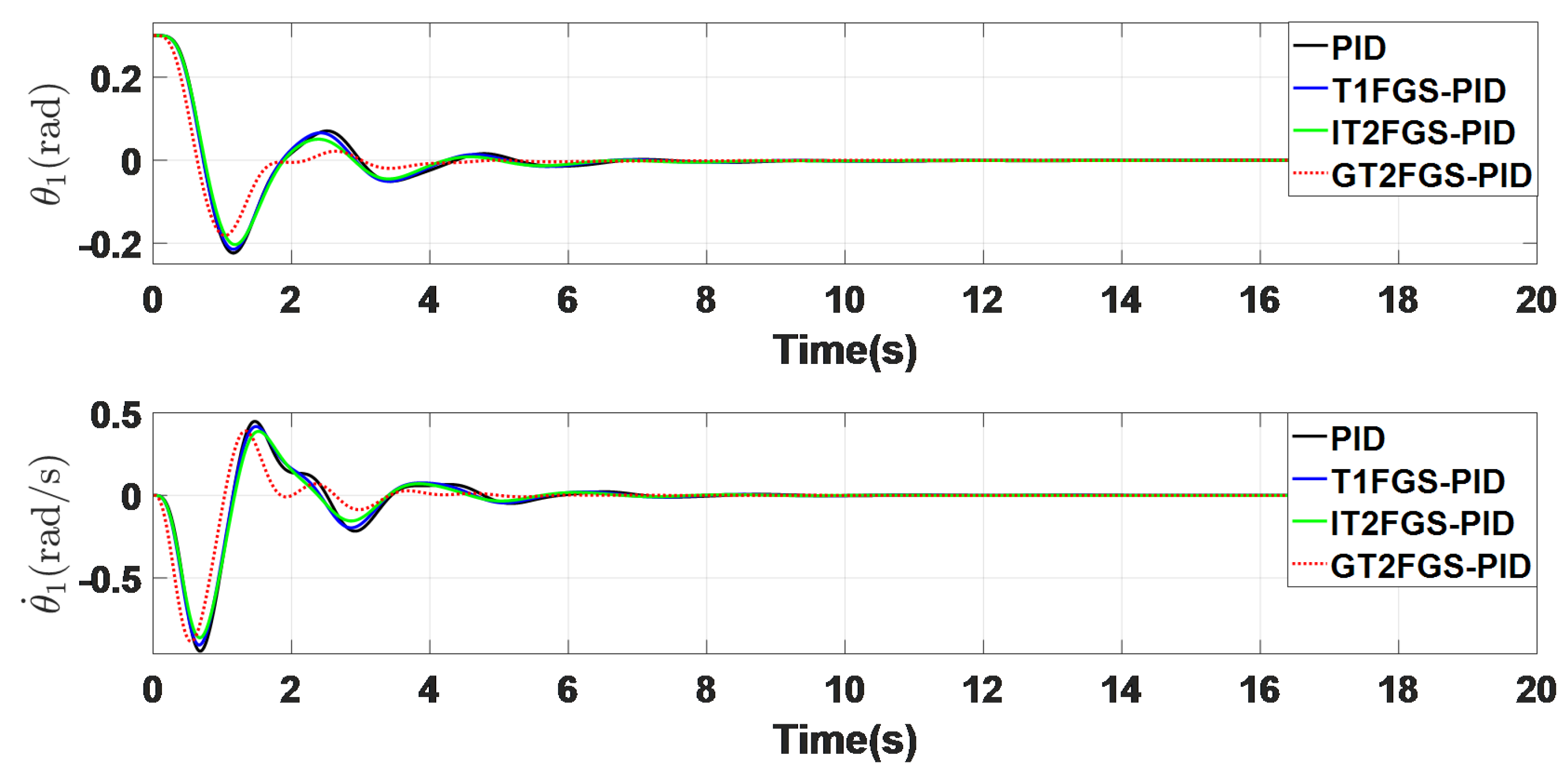
4.1. No Disturbance Scenario

Figure 12 depicts the system response of the photoelectric tracking system under no external disturbance. The initial position is set to X 0 = 0.3 , with the desired steady-state position being X f = 0 . In this scenario, the external disturbance is assumed to be 0.
By analyzing the system response curves and the data in Table 2, it is evident that while the performance of the T1FGS-PID and IT2FGS-PID controllers is comparable to the standard PID controller in some metrics, certain performance indicators are inferior. However, the GT2FGS-PID controller consistently outperforms all the others across all key metrics. Notably, the GT2FGS-PID controller exhibits superior speed, returning the system to its steady-state position more rapidly than its counterparts. This controller also demonstrates enhanced stability and responsiveness, ensuring a quicker and more precise convergence to the desired target without sacrificing system stability. The results suggest that the GT2FGS-PID controller is particularly well-suited for applications requiring fast and stable control in the absence of external disturbances.

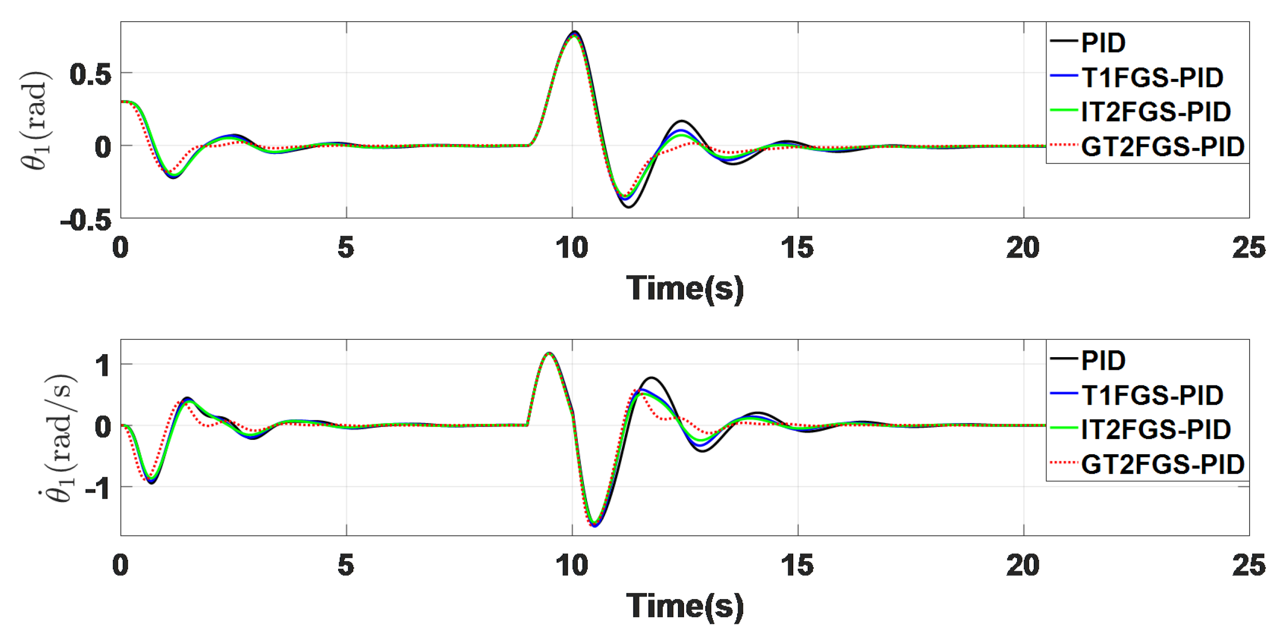
4.2. Response to External Disturbance

In this scenario, a square wave disturbance of ± 0.5 V is introduced during the simulation period from 9 to 10 s. Figure 13 shows the system response of the photoelectric tracking system under the influence of this external disturbance. From the figures, it is clear that, although all controllers eventually achieve stability, the GT2FGS-PID controller demonstrates the best disturbance rejection capability.
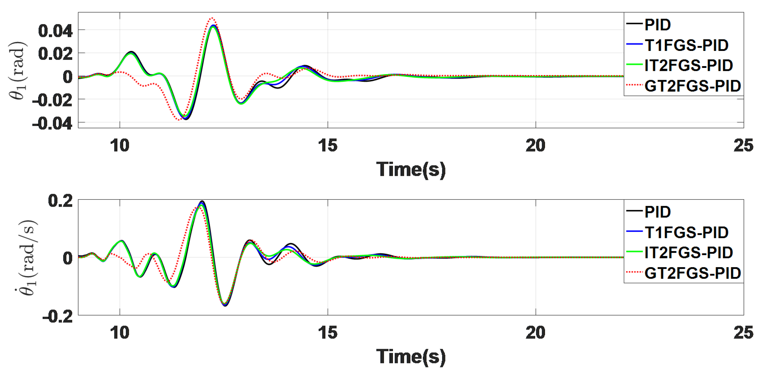
Figure 14 illustrates the system’s response when the external disturbance is increased to ± 1.0 V . As observed from Figure 13 and Figure 14 and the data presented in Table 3 and Table 4, the proposed GT2FGS-PID controller maintains its superior performance even as the external disturbance increases from ± 0.5 V to ± 1.0 V .
The results indicate that the GT2FGS-PID controller exhibits robust adaptability to external disturbances, outperforming the other controllers in terms of stability, speed, and precision, making it particularly suitable for environments where systems are exposed to varying and significant disturbances.

4.3. Response to Random Disturbance

Figure 15 illustrates the system response under random disturbance, while Figure 16 shows the disturbance profile. After the system stabilizes, at the simulation time of 9 s, random disturbance is applied for a duration of 3 s. To provide a clearer comparison of the four controllers, the response curves are shown starting from 10 s. Based on the response graphs and the data in Table 5, the advantages of the GT2FGS-PID controller are evident, particularly in terms of smaller vibration amplitude and shorter settling time.
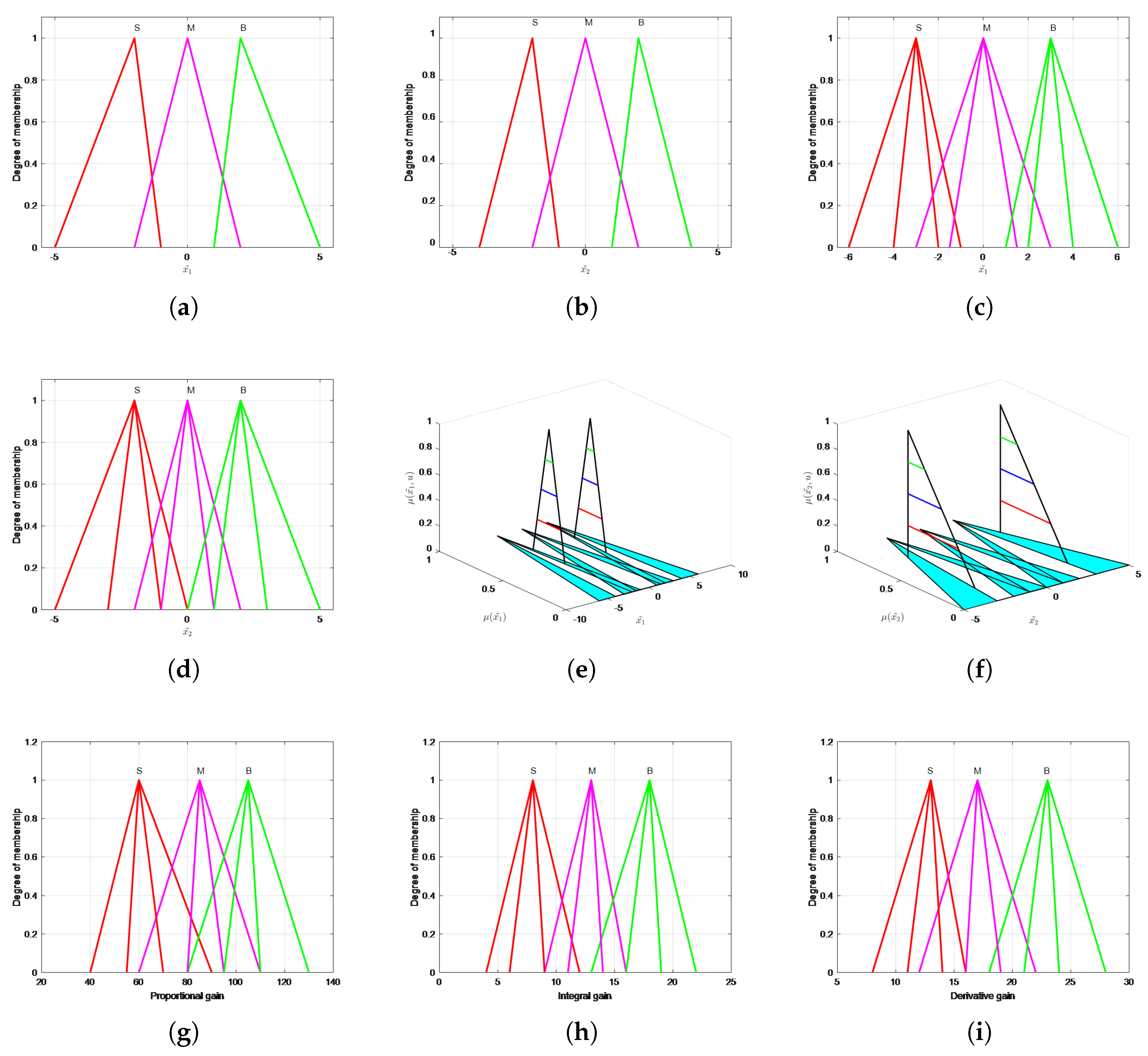
In each simulation graph, the control trends of all four controllers are consistent. This is due to the role of the fuzzy controller, which adjusts the three PID parameters ( K p , K i , K d ) in real time, while the PID controller makes the control decisions and generates the output. The primary function of the fuzzy logic controller is twofold: First, it leverages expert knowledge to adjust PID parameters dynamically in response to external changes, even in the presence of uncertain or imprecise nonlinear models. Second, in environments with high uncertainty, the fuzzy controller mitigates the effects of external disturbances more effectively.
The simulation results demonstrate a progressive improvement in control performance from PID to T1FGS-PID, then to IT2FGS-PID, and finally to GT2FGS-PID. Additionally, their disturbance rejection capabilities also increase accordingly. This not only highlights the superior ability of the General Type-2 Fuzzy Logic Controller (GT2FLC) in handling uncertainty but also confirms the effectiveness of combining fuzzy logic with PID control strategies.

5. Experimental Validation

Figure 17 presents a high-precision Pointing and Tracking System (PTS) with a dual-axis, dual-tip tilt mirror tracking mechanism. The system is composed of three main components: a target simulation unit, which includes a signal-emitting device (laser) and a target mirror movement adjustment mechanism, a monitoring unit, comprising a position-sensitive detector and an image charge-coupled device (CCD), and a control unit, which operates the tracking mirror. In operation, the laser functions as the signal emitter to simulate the target’s motion, while the target mirror within the simulation unit adjusts the target’s movement. The tracking mirror, driven by a motor, reflects the signal onto the position-sensitive detector. The CCD detects the steady-state error after receiving the target signal and subsequently sends this error information to the position controller.
The transfer function of the control system is given by
G ( s ) = θ a ( s ) U a ( s ) = 1883 s 2 + 24.3 s + 1340 1 0.0009 s + 1
To enhance the practical application of memristor circuits, this section presents the implementation of a printed circuit board (PCB) for the flux-controlled memristor circuit, as illustrated in Figure 18a. To incorporate a differentiation module and improve the circuit’s noise immunity, a filtering circuit was added. The overall circuit consists of two main parts. The first part is the memristor, with the fabricated PCB measuring 3 × 3.2 cm. It features two sets of pin headers: the upper header has three pins corresponding to the memristor’s input, output terminals, and an external control signal terminal, while the lower header serves as the power supply connection. The physical implementation of the memristor circuit is depicted in Figure 18b. Figure 18c illustrates the experimental setup, where the FSM serves as the control object. The memristor circuit board is integrated into the MPID module, with the signal generator providing excitation signals. A DSP module is programmed with a fuzzy control algorithm, and the oscilloscope is used to analyze and compare the system’s response. This setup facilitates the real-time testing of the memristor-based control system, allowing for the assessment of its dynamic performance in practical applications.

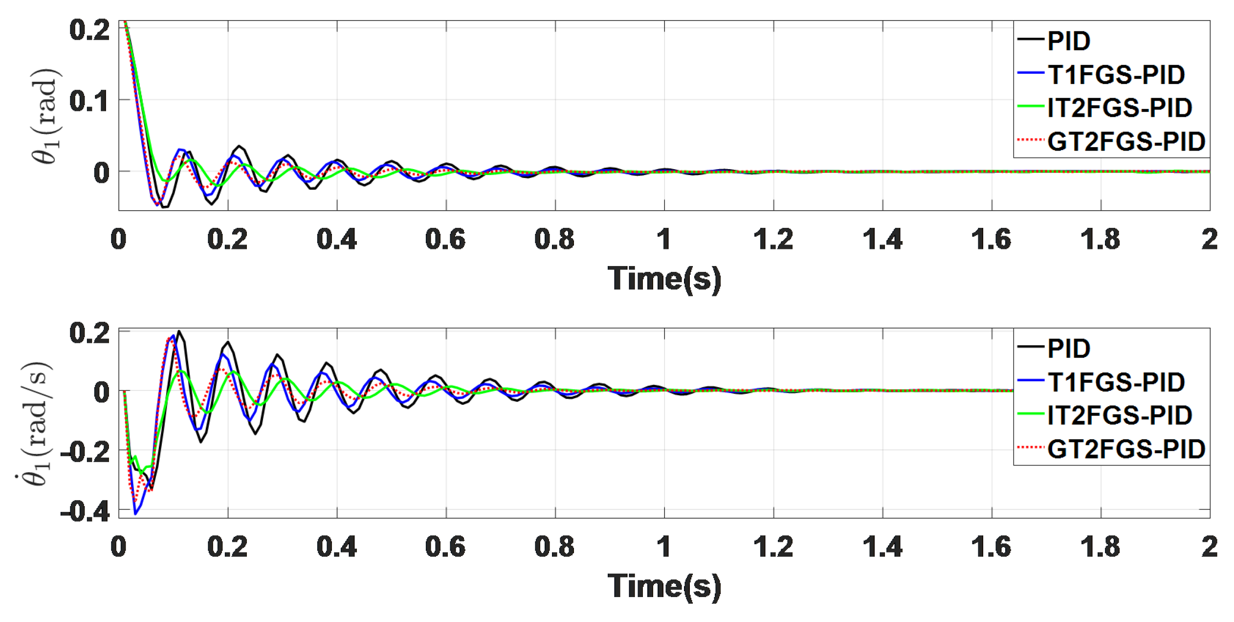
5.1. No Disturbance Scenario

In this scenario, external disturbance is set to zero. As shown in 
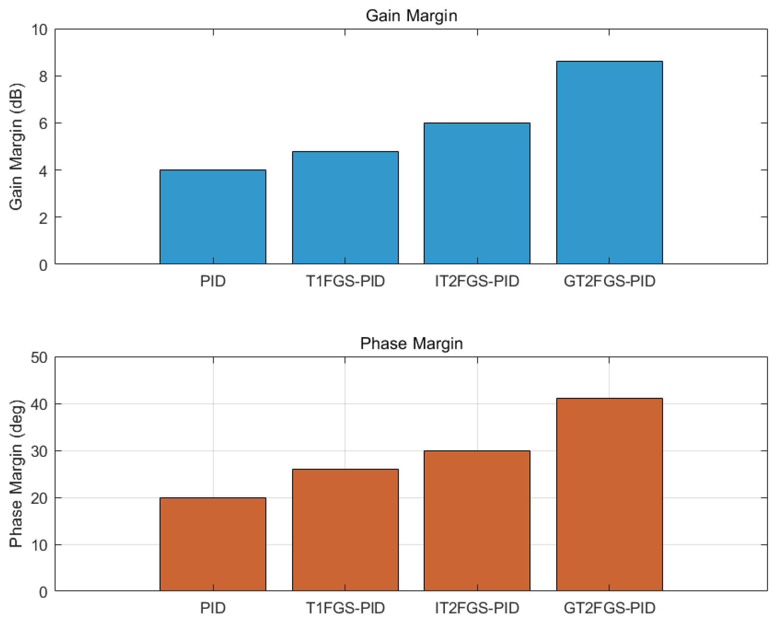
Figure 19, the system responses of the four controllers align with the results from previous numerical simulations. The GT2FGS-PID and IT2FGS-PID controllers exhibit superior dynamic performance compared to the PID and T1FGS-PID controllers, with both reaching the equilibrium position more rapidly. While the GT2FGS-PID controller shows slightly larger oscillations compared to IT2FGS-PID, it demonstrates faster response times. To further validate the superiority of the proposed method, this chapter incorporates stability margin analysis as shown in Figure 20 and steady-state error evaluation as additional performance metrics. A comparison of the data in Table 6 further confirms that, overall, the GT2FGS-PID controller offers better control performance.

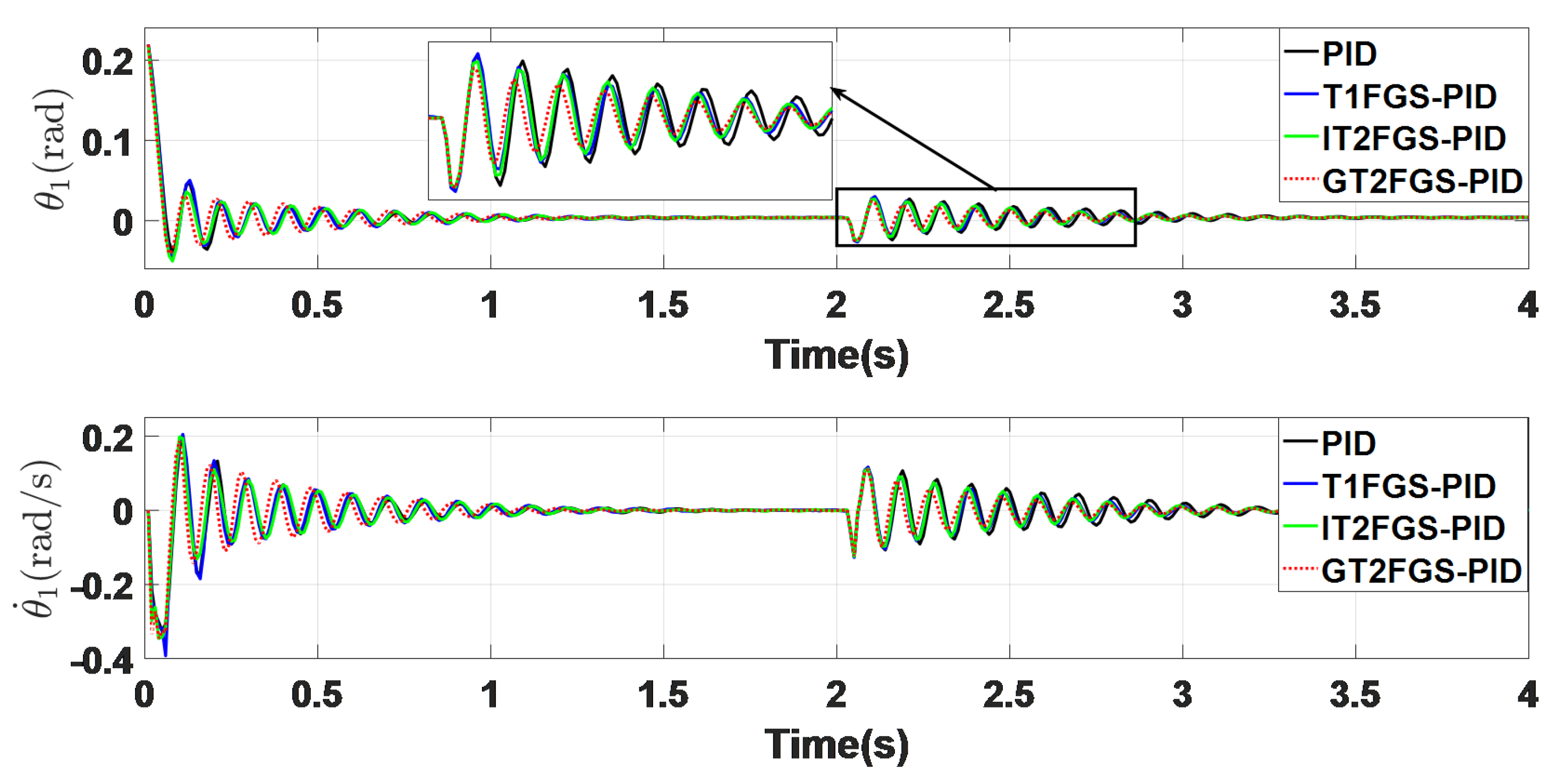
5.2. Under External Disturbance

In this scenario, the robustness of the controllers in the presence of external disturbances was evaluated. As shown in Figure 21 and Figure 22 and summarized in Table 7, an external disturbance was introduced at the simulation time of 2 s. The GT2FGS-PID controller exhibited smaller fluctuations in response to the disturbance and reached the equilibrium position faster than the other controllers, demonstrating superior disturbance rejection capabilities.

6. Discussion

The experimental validation of the GT2FGS-PID controller yielded more realistic system responses for the photonic tracking system. The simulation results consistently demonstrated that the GT2FGS-PID controller offers superior control performance and enhanced handling of external uncertainties. This section focused on two experimental scenarios: one without disturbances and another with external disturbances. In the disturbance-free scenario, comparing the numerical simulations and experimental results for the GT2FGS-PID controller reveals a significant increase in the time required to reach system stability. In the numerical simulation, all four controllers achieved stability at 0.08 s (with a sampling interval of 0.01 s and eight sampling points). However, in the experimental setting, stability was only reached at 0.21 s (with a sampling interval of 0.15 s and 1.4 sampling points). This discrepancy is primarily due to differences in the experimental environment, where the system response was less ideal compared to the simulation. In the real system, factors such as inertia and unforeseen disturbances affected the response. Additionally, the increased sampling interval and communication delays between platforms led to signal latency, further diminishing controller performance. In the presence of external disturbances, comparing the numerical simulations and experimental results for the GT2FGS-PID controller reveals a noticeable increase in the number of oscillations near the equilibrium position in the experimental setting. This is partly due to the system’s inherent inertia and dynamic properties. Additionally, the photonic tracking system typically requires multiple adjustments to reach the equilibrium position, which explains the increased oscillation observed in the experimental results. Overall, the experiments conducted in a real-world environment validated the effectiveness and robustness of the GT2FGS-PID controller for equilibrium control of the photonic tracking system. The results confirm its superior performance in achieving stable control, even in the presence of uncertainties and disturbances. Further research and improvement are still needed. First, the generalized type-2 fuzzy control method used in this study relies on multiple α -level sets to represent the three-dimensional membership functions. While this approach reduces computational complexity, it also compromises the precision of the controller. Future work should focus on optimizing the balance between computational efficiency and precision by simplifying the generalized type-2 fuzzy membership functions without sacrificing accuracy. Additionally, due to the high computational complexity involved in calculating controller parameters, this study employed offline optimization of the adjustable parameters. To improve practical applicability, future work should aim to implement real-time online optimization, allowing the controller to flexibly handle various external disturbances in real-world applications.

7. Conclusions

This paper presents the design and implementation of a GT2FGS-PID controller, applied to a photonic tracking system. The effectiveness of the controller was validated through numerical simulations conducted on the MATLAB platform. The GT2FGS-PID controller combines a generalized type-2 fuzzy gain scheduling (GT2FGS) system with a traditional PID controller. By leveraging the adaptive decision-making capabilities of the generalized type-2 fuzzy system, the controller is able to adjust PID parameters in real time to adapt to external variations, thereby enhancing the flexibility and robustness of the control strategy. To further validate the controller’s performance, a series of numerical simulations were conducted under various conditions, specifically addressing the control challenges posed by the photonic tracking system. Additionally, experimental tests were carried out to capture the controller’s real-world system response. The results demonstrated that the GT2FGS-PID controller not only ensures system stability but also exhibits strong robustness against external disturbances. In summary, the GT2FGS-PID controller proves to be an effective solution for complex control systems such as photonic tracking, offering improved stability, flexibility, and resilience against uncertainties and external disturbances.

Author Contributions

Conceptualization, T.F.; Formal analysis, S.D.; Methodology, T.F.; Resources, X.C. and Y.M.; Software, T.F.; Supervision, Y.M.; Writing—original draft, T.F.; Writing—review and editing, C.Z. All authors have read and agreed to the published version of the manuscript.

Funding

This research received no external funding.

Institutional Review Board Statement

Not applicable.

Informed Consent Statement

Not applicable.

Data Availability Statement

Data are contained within the article.

Conflicts of Interest

The authors declare no conflicts of interest.

References

  1. Guzmán, J.L.; Hägglund, T. Tuning Rules for Feedforward Control from Measurable Disturbances Combined with PID Control: A Review; Taylor & Francis: Abingdon, UK, 2024; Volume 97, pp. 2–15. [Google Scholar]
  2. Patil, R.S.; Jadhav, S.P.; Patil, M.D. Review of Intelligent and Nature-Inspired Algorithms-Based Methods for Tuning PID Controllers in Industrial Applications. J. Robot. Control (JRC) 2024, 5, 336–358. [Google Scholar]
  3. Gopi, P.; Reddy, S.V.; Bajaj, M.; Zaitsev, I.; Prokop, L. Performance and robustness analysis of V-Tiger PID controller for automatic voltage regulator. Sci. Rep. 2024, 14, 7867. [Google Scholar] [CrossRef] [PubMed]
  4. Wang, T.; Dong, R.; Zhang, R.; Qin, D. Research on stability design of differential drive fork-type AGV based on PID control. Electronics 2020, 9, 1072. [Google Scholar] [CrossRef]
  5. Chaturvedi, S.; Kumar, N.; Kumar, R. A PSO-optimized novel PID neural network model for temperature control of jacketed CSTR: Design, simulation, and a comparative study. Soft Comput. 2024, 28, 4759–4773. [Google Scholar] [CrossRef]
  6. Jin, X.; Liu, J.; Chen, Z.; Xu, Z.; Ji, J. Precision control system of rice potting and transplanting machine based on GA-Fuzzy PID controller. Comput. Electron. Agric. 2024, 220, 108912. [Google Scholar] [CrossRef]
  7. Adesanya, M.A.; Obasekore, H.; Rabiu, A.; Na, W.H.; Ogunlowo, Q.O.; Akpenpuun, T.D.; Kim, M.H.; Kim, H.T.; Kang, B.Y.; Lee, H.W. Deep reinforcement learning for PID parameter tuning in greenhouse HVAC system energy Optimization: A TRNSYS-Python cosimulation approach. Expert Syst. Appl. 2024, 252, 124126. [Google Scholar] [CrossRef]
  8. Li, M.; Xu, J.; Wang, Z.; Liu, S. Optimization of the semi-active-suspension control of BP neural network PID based on the sparrow search algorithm. Sensors 2024, 24, 1757. [Google Scholar] [CrossRef]
  9. Yin, L.; Zheng, D. Decomposition prediction fractional-order PID reinforcement learning for short-term smart generation control of integrated energy systems. Appl. Energy 2024, 355, 122246. [Google Scholar] [CrossRef]
  10. Ali, G.; Aly, H.; Little, T. Automatic generation control of a multi-area hybrid renewable energy system using a proposed novel GA-fuzzy logic self-tuning PID controller. Energies 2024, 17, 2000. [Google Scholar] [CrossRef]
  11. Cetinsaya, B.; Reiners, D.; Cruz-Neira, C. From PID to swarms: A decade of advancements in drone control and path planning-A systematic review (2013–2023). Swarm Evol. Comput. 2024, 89, 101626. [Google Scholar] [CrossRef]
  12. He, C.; Zhou, D.; Sheng, W.; Xu, M.; Xi, Q.; Chen, Q. Fuzzy-PID controller design for RGV speed track based on improved PSO algorithm. J. Braz. Soc. Mech. Sci. Eng. 2024, 46, 669. [Google Scholar] [CrossRef]
  13. Wang, Y.; Wang, Z.; Zou, L.; Dong, H. Observer-based fuzzy PID tracking control under try-once-discard communication protocol: An affine fuzzy model approach. IEEE Trans. Fuzzy Syst. 2024, 32, 2352–2365. [Google Scholar] [CrossRef]
  14. Dogru, O.; Velswamy, K.; Ibrahim, F.; Wu, Y.; Sundaramoorthy, A.S.; Huang, B.; Xu, S.; Nixon, M.; Bell, N. Reinforcement learning approach to autonomous PID tuning. Comput. Chem. Eng. 2022, 161, 107760. [Google Scholar] [CrossRef]
  15. Tang, H.H.; Ahmad, N.S. Fuzzy logic approach for controlling uncertain and nonlinear systems: A comprehensive review of applications and advances. Syst. Sci. Control. Eng. 2024, 12, 2394429. [Google Scholar] [CrossRef]
  16. Ridzuan, A.; Rahman, H.A. Real Time Comparison between PID and Fuzzy Logic Controller for DC Motor Speed Control. Evol. Electr. Electron. Eng. 2024, 5, 512–520. [Google Scholar]
  17. Mohindru, P. Review on PID, fuzzy and hybrid fuzzy PID controllers for controlling non-linear dynamic behaviour of chemical plants. Artif. Intell. Rev. 2024, 57, 97. [Google Scholar] [CrossRef]
  18. Sanguino, T.d.J.M.; Domínguez, J.M.L. Design and stabilization of a Coandă effect-based UAV: Comparative study between fuzzy logic and PID control approaches. Robot. Auton. Syst. 2024, 175, 104662. [Google Scholar] [CrossRef]
  19. Mendel, J.M. Type-1 Fuzzy Sets and Fuzzy Logic; Springer: Cham, Switzerland, 2024; pp. 17–73. [Google Scholar]
  20. Han, J.; Shan, X.; Liu, H.; Xiao, J.; Huang, T. Fuzzy Gain Scheduling PID Control of a Hybrid Robot Based on Dynamic Characteristics; Elsevier: Amsterdam, The Netherlands, 2023; Volume 184, p. 105283. [Google Scholar]
  21. Zhang, B.; Niu, P.; Guo, X.; He, J. Fuzzy PID control of permanent magnet synchronous motor electric steering engine by improved beetle antennae search algorithm. Sci. Rep. 2024, 14, 2898. [Google Scholar] [CrossRef]
  22. Acharya, D.; Das, D.K. A Novel PID Controller for Pressure Control of Artificial Ventilator Using Optimal Rule Based Fuzzy Inference System with RCTO Algorithm; Nature Publishing Group UK London: London, UK, 2023; Volume 13, p. 9281. [Google Scholar]
  23. Li, K.; Bai, Y.; Zhou, H. Research on Quadrotor Control Based on Genetic Algorithm and Particle Swarm Optimization for PID Tuning and Fuzzy Control-Based Linear Active Disturbance Rejection Control. Electronics 2024, 13, 4386. [Google Scholar] [CrossRef]
  24. Wang, S.; Liu, X.; Zhang, X.; Zhao, Y.; Xiong, Y. A Fuzzy Logic Control-Based Adaptive Gear-Shifting Considering Load Variation and Slope Gradient for Multi-Speed Automated Manual Transmission (AMT) Electric Heavy-Duty Commercial Vehicles. Electronics 2024, 13, 4458. [Google Scholar] [CrossRef]
  25. Zamani, A.A.; Etedali, S. Seismic structural control using magneto-rheological dampers: A decentralized interval type-2 fractional-order fuzzy PID controller optimized based on energy concepts. ISA Trans. 2023, 137, 288–302. [Google Scholar] [CrossRef] [PubMed]
  26. Saraswat, R.; Suhag, S. Type-2 fuzzy logic PID control for efficient power balance in an AC microgrid. Sustain. Energy Technol. Assessments 2023, 56, 103048. [Google Scholar] [CrossRef]
  27. Xian, W.; Qi, Q.; Liu, W.; Liu, Y.; Li, D.; Wang, Y. Control of quadrotor robot via optimized nonlinear type-2 fuzzy fractional PID with fractional filter: Theory and experiment. Aerosp. Sci. Technol. 2024, 151, 109286. [Google Scholar] [CrossRef]
  28. Namadchian, Z.; Shoeibi, A.; Zare, A.; Gorriz, J.M.; Lam, H.K.; Ling, S.H. Stability Analysis of Dynamic General Type-2 Fuzzy Control System With Uncertainty. IEEE Trans. Syst. Man Cybern. Syst. 2023, 54, 1755–1767. [Google Scholar] [CrossRef]
  29. Lin, P.; Li, C.; Wang, Z.; Li, Y.; Jiang, H.; Song, W.; Rao, M.; Zhuo, Y.; Upadhyay, N.K.; Barnell, M.; et al. Three-dimensional memristor circuits as complex neural networks. Nat. Electron. 2020, 3, 225–232. [Google Scholar] [CrossRef]
  30. Sun, K.; Chen, J.; Yan, X. The future of memristors: Materials engineering and neural networks. Adv. Funct. Mater. 2021, 31, 2006773. [Google Scholar] [CrossRef]
  31. Lin, H.; Wang, C.; Hong, Q.; Sun, Y. A multi-stable memristor and its application in a neural network. IEEE Trans. Circuits Syst. II Express Briefs 2020, 67, 3472–3476. [Google Scholar] [CrossRef]
  32. Altınkaya, H.; Ekmekci, D. Tuning of PID Controller in PLC-Based Automatic Voltage Regulator System Using Adaptive Artificial Bee Colony–Fuzzy Logic Algorithm. Electronics 2024, 13, 5039. [Google Scholar] [CrossRef]
  33. Sowmya, R.R.; Sumanth, A.; Kailath, B.J.; Dixit, T. Development of accurate model for memristor based filters and oscillators: Amplitude, frequency and ramp-rate dependent analysis. IEEE Trans. Circuits Syst. II Express Briefs 2023, 71, 872–876. [Google Scholar] [CrossRef]
  34. Zadeh, L.A. Fuzzy Logic; Springer: New York, NY, USA, 2023; pp. 19–49. [Google Scholar]
  35. Che, Y.; Zheng, G.; Li, Y.; Hui, X.; Li, Y. Unmanned Agricultural Machine Operation System in Farmland Based on Improved Fuzzy Adaptive Priority-Driven Control Algorithm. Electronics 2024, 13, 4141. [Google Scholar] [CrossRef]
  36. Beke, A.; Kumbasar, T. More than accuracy: A composite learning framework for interval type-2 fuzzy logic systems. IEEE Trans. Fuzzy Syst. 2022, 31, 734–744. [Google Scholar] [CrossRef]
  37. Bernal, E.; Lagunes, M.L.; Castillo, O.; Soria, J.; Valdez, F. Optimization of type-2 fuzzy logic controller design using the GSO and FA algorithms. Int. J. Fuzzy Syst. 2021, 23, 42–57. [Google Scholar] [CrossRef]
  38. Georgakilas, E.; Alimisis, V.; Gennis, G.; Aletraris, C.; Dimas, C.; Sotiriadis, P.P. An ultra-low power fully-programmable analog general purpose type-2 fuzzy inference system. AEU-Int. J. Electron. Commun. 2023, 170, 154824. [Google Scholar] [CrossRef]
Figure 1. Basic relationships of circuit elements.
Electronics 14 01178 g001
Figure 2. Memristor volt–ampere curve.
Electronics 14 01178 g002
Figure 3. Type-1 fuzzy logic system structure block diagram.
Electronics 14 01178 g003
Figure 4. Type-1 fuzzy set (triangle membership function).
Electronics 14 01178 g004
Figure 5. Internal type-2 fuzzy logic system structure block diagram.
Electronics 14 01178 g005
Figure 6. Internal type-2 fuzzy set.
Electronics 14 01178 g006
Figure 7. The elements of a general type-2 fuzzy set.
Electronics 14 01178 g007
Figure 8. Flux-controlled memristive circuit.
Electronics 14 01178 g008
Figure 9. Memristor V-I Waveform.
Electronics 14 01178 g009
Figure 10. GT2FGS-PID controller overall structure.
Electronics 14 01178 g010
Figure 11. The membership functions of each controller. (a) T1FGS-PID controller input membership e function. (b) T1FGS-PID controller input membership Δ e function. (c) IT2FGS-PID controller input membership e function. (d) IT2FGS-PID controller input membership Δ e function. (e) GT2FGS-PID controller input membership e function. (f) GT2FGS-PID controller input membership Δ e function. (g) The membership function of the output K p . (h) The membership function of the output K i . (i) The membership function of the output K d .
Electronics 14 01178 g011
Figure 12. System response diagram without interference.
Electronics 14 01178 g012
Figure 13. System response diagram under external interference (disturbance = ± 0.5 V ).
Electronics 14 01178 g013
Figure 14. System response diagram under external interference (disturbance = ± 1.0 V ).
Electronics 14 01178 g014
Figure 15. System response graph under random disturbance.
Electronics 14 01178 g015
Figure 16. Random interference diagram.
Electronics 14 01178 g016
Figure 17. PTS subsystem.
Electronics 14 01178 g017
Figure 18. The test platform.
Electronics 14 01178 g018
Figure 19. System response diagram without interference (GT2FGS-PID).
Electronics 14 01178 g019
Figure 20. Stability Margin Comparison.
Electronics 14 01178 g020
Figure 21. System response diagram under external interference.
Electronics 14 01178 g021
Figure 22. Stability margin comparison under external interference.
Electronics 14 01178 g022
Table 1. Table of fuzzy rules.
e e
K p K i K d
S M B S M B S M B
SMSMBSBMBM
MBMBBMBSBS
BMSMMSMMBM
Table 2. Performance indicators in the absence of interference.
Performance Indicatorsx
PIDT1FGS-PIDIT2FGS-PIDGT2FGS-PID
ISE0.0700.0670.0640.048
IAE0.4330.4180.3950.282
ITAE0.7910.7280.650.329
Table 3. Performance indicators under external interference (disturbance = ± 0.5 V ).
Performance Indicatorsx
PIDT1FGS-PIDIT2FGS-PIDGT2FGS-PID
ISE0.0900.0850.0810.064
IAE0.6850.6540.6150.485
ITAE3.6393.3733.0882.544
Table 4. Performance indicators under external interference (disturbance = ± 1.0 V ).
Performance Indicatorsx
PIDT1FGS-PIDIT2FGS-PIDGT2FGS-PID
ISE0.6370.5670.5410.511
IAE1.8091.6301.5391.349
ITAE16.44114.29713.31711.899
Table 5. Performance indicators under random disturbance.
Performance Indicatorsx
PIDT1FGS-PIDIT2FGS-PIDGT2FGS-PID
ISE0.0720.0690.0660.050
IAE0.5030.4860.4600.348
ITAE1.6761.5881.4661.140
Table 6. Performance indicators without interference (GT2FGS-PID).
Performance Indicatorsx
PIDT1FGS-PIDIT2FGS-PIDGT2FGS-PID
ISE0.0130.0090.0100.008
IAE0.2520.1810.1460.139
ITAE1.1040.6910.5220.437
e(+)0.0080.0060.0040.003
Table 7. Performance indicators under external interference.
Performance Indicatorsx
PID T1FGS-PID IT2FGS-PID GT2FGS-PID
ISE0.0160.0150.0130.012
IAE0.4850.4780.4580.434
ITAE10.5609.9269.7889.046
e(+)0.130.090.040.01
Disclaimer/Publisher’s Note: The statements, opinions and data contained in all publications are solely those of the individual author(s) and contributor(s) and not of MDPI and/or the editor(s). MDPI and/or the editor(s) disclaim responsibility for any injury to people or property resulting from any ideas, methods, instructions or products referred to in the content.

