
A Study on Novel Current Controller for Improving Transient Characteristics in Direct Current Power Systems


Abstract
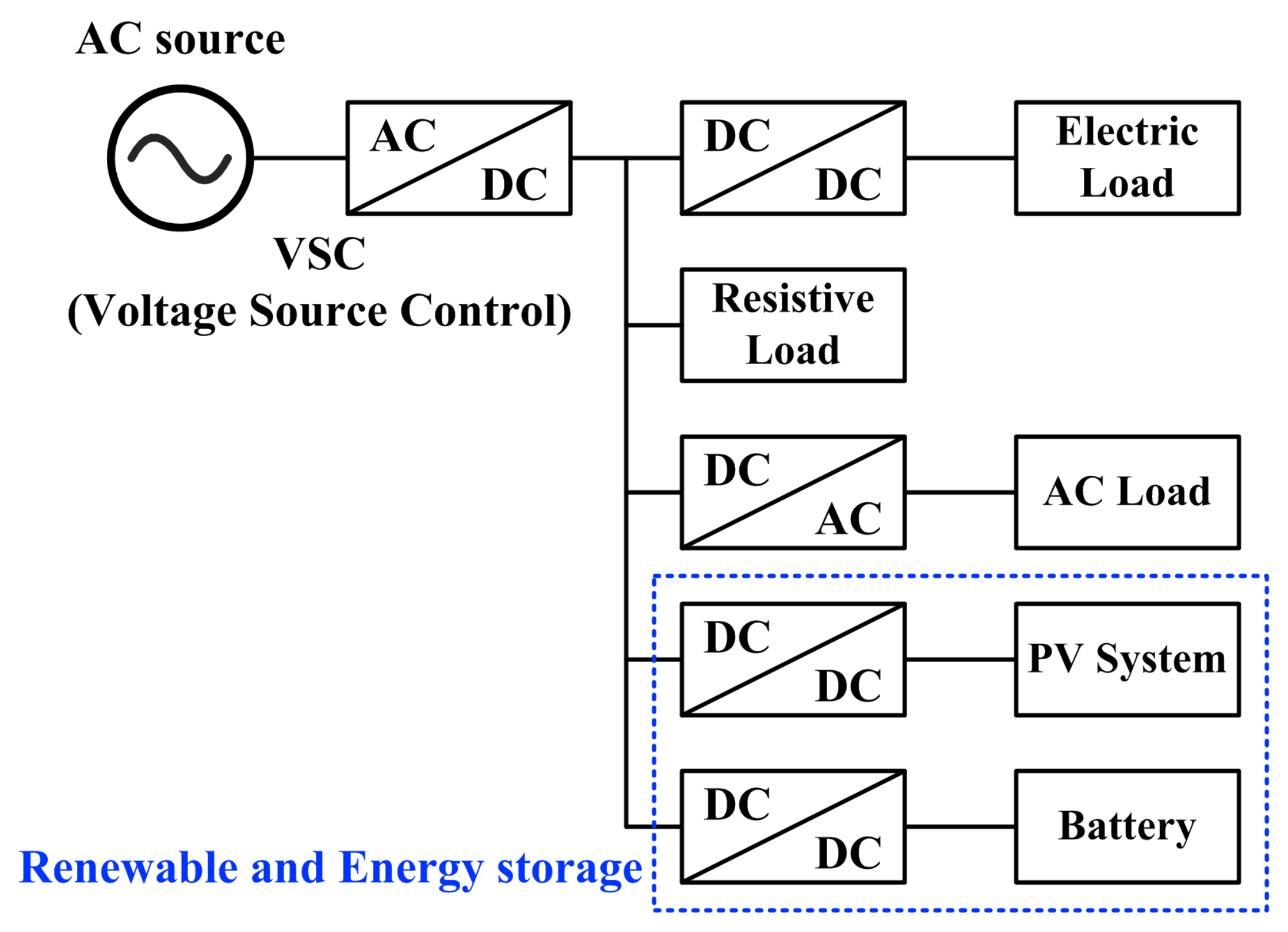
1. Introduction
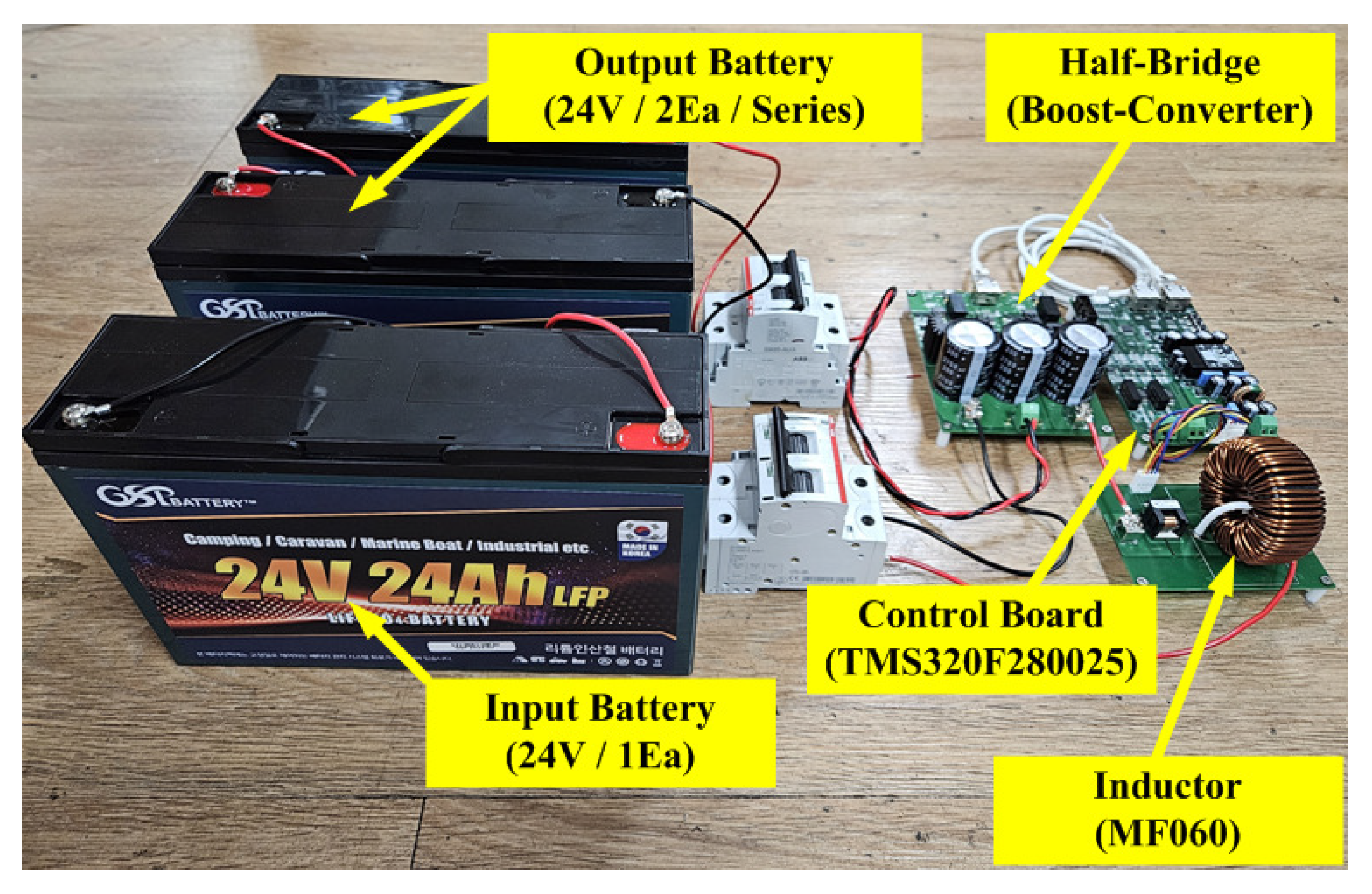
2. Bidirectional Boost Converter
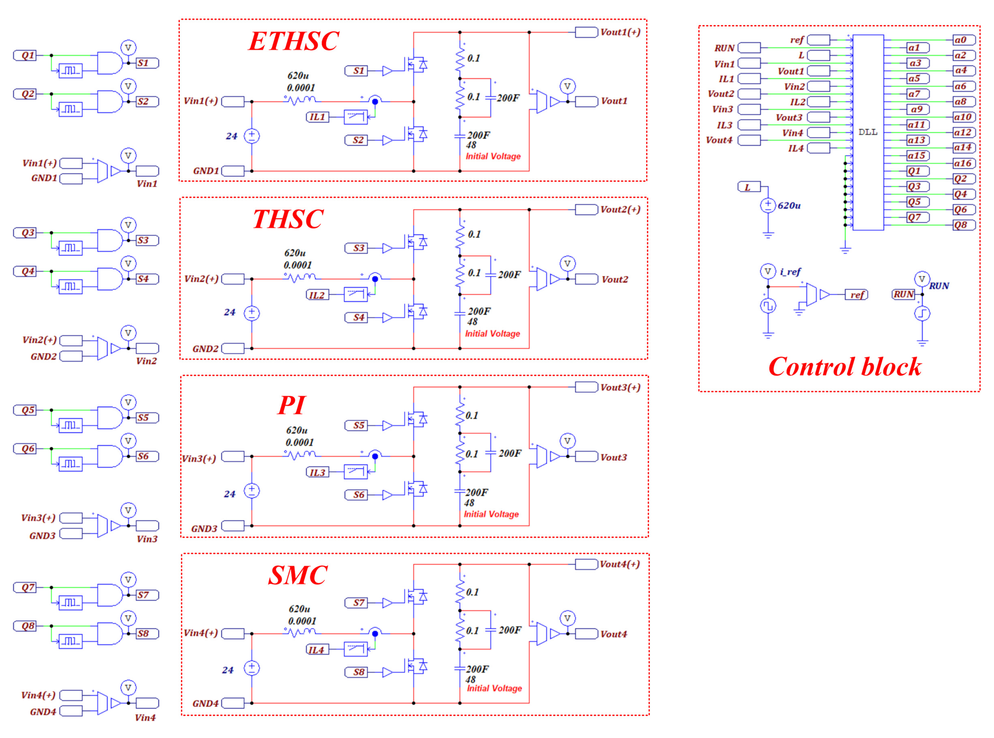
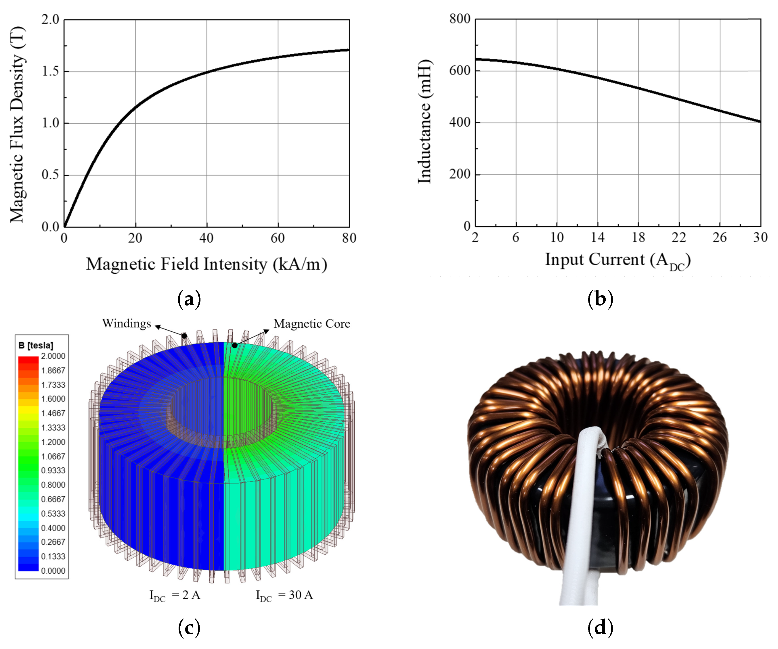
2.1. Hardware Description
2.2. Bidirectional Converter Controllers
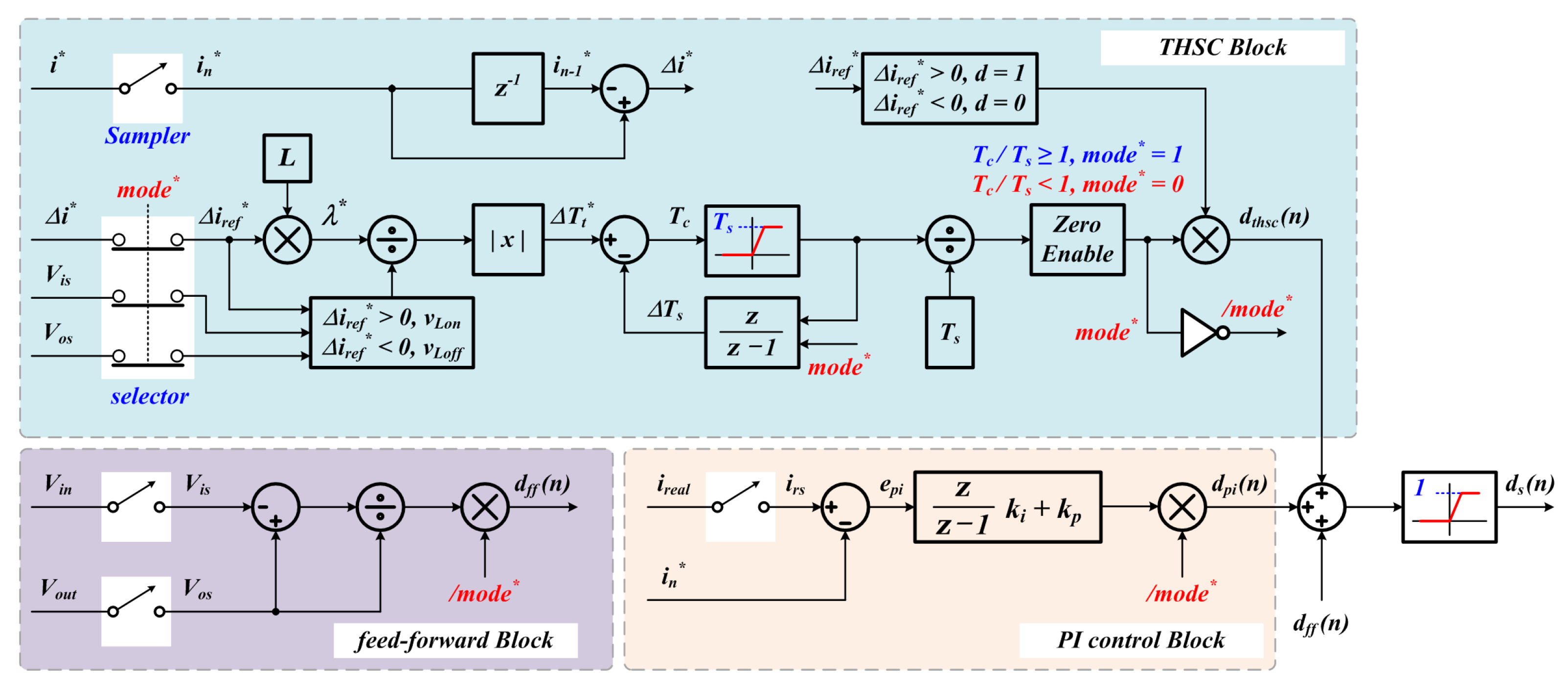
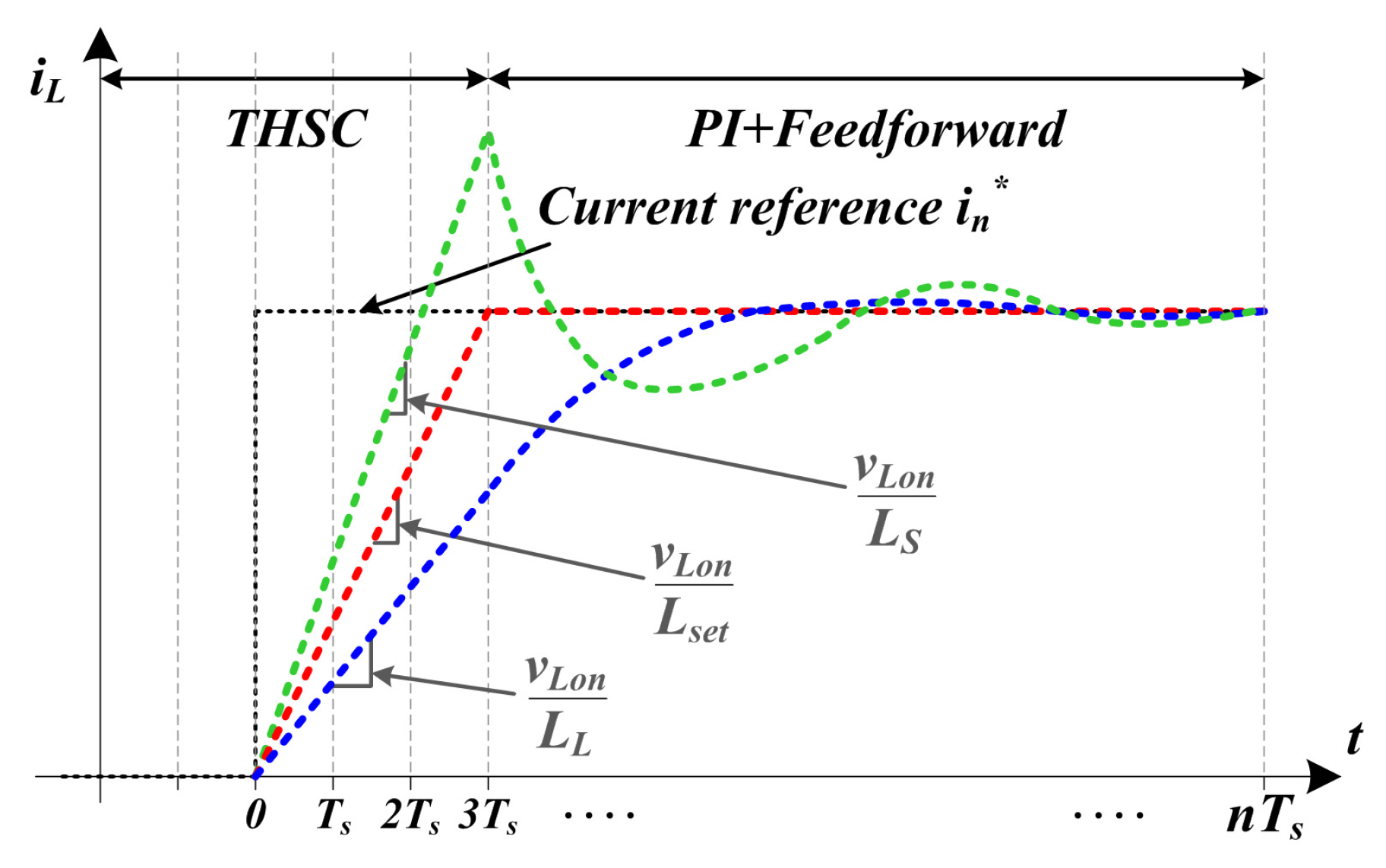
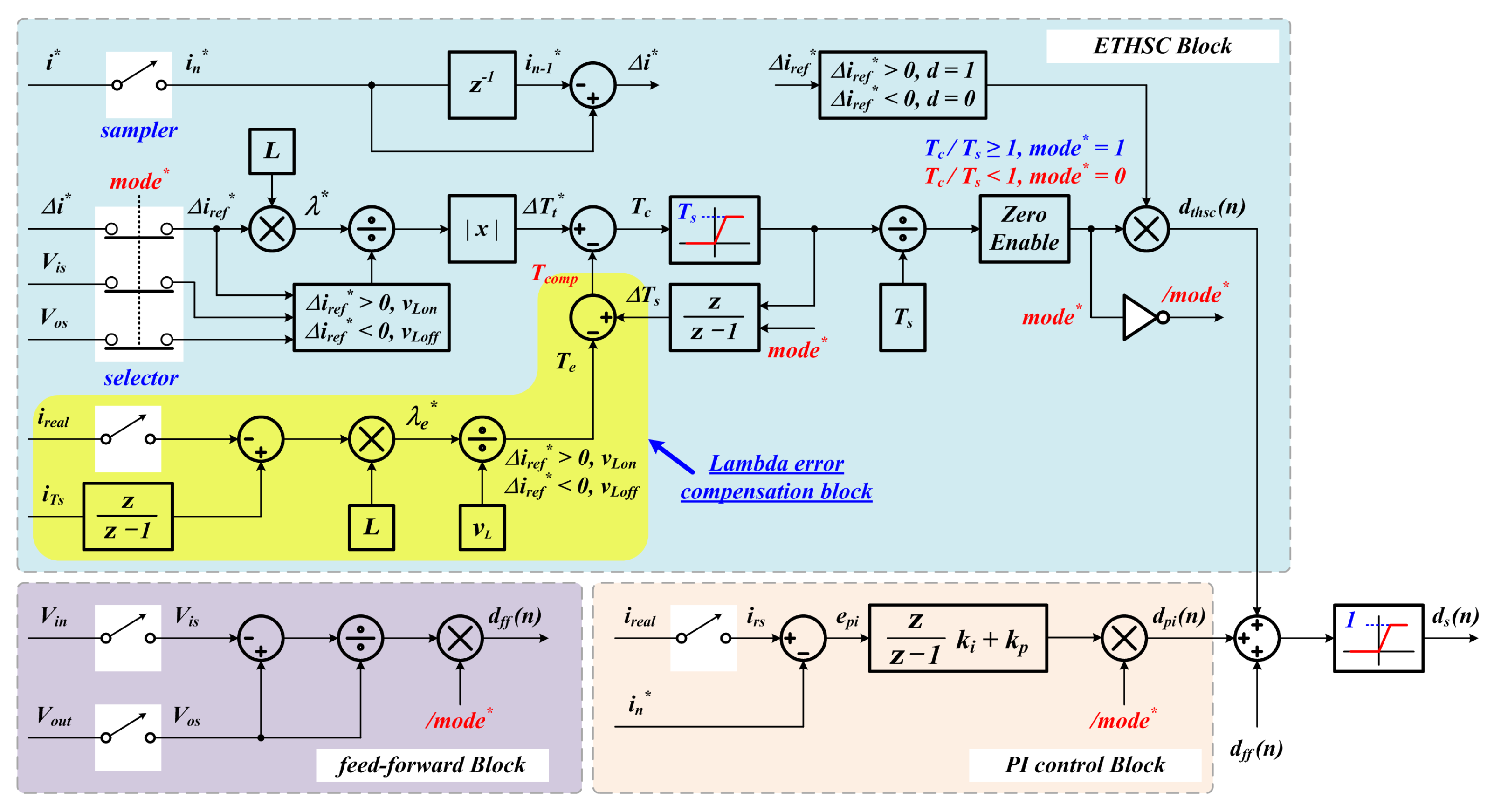
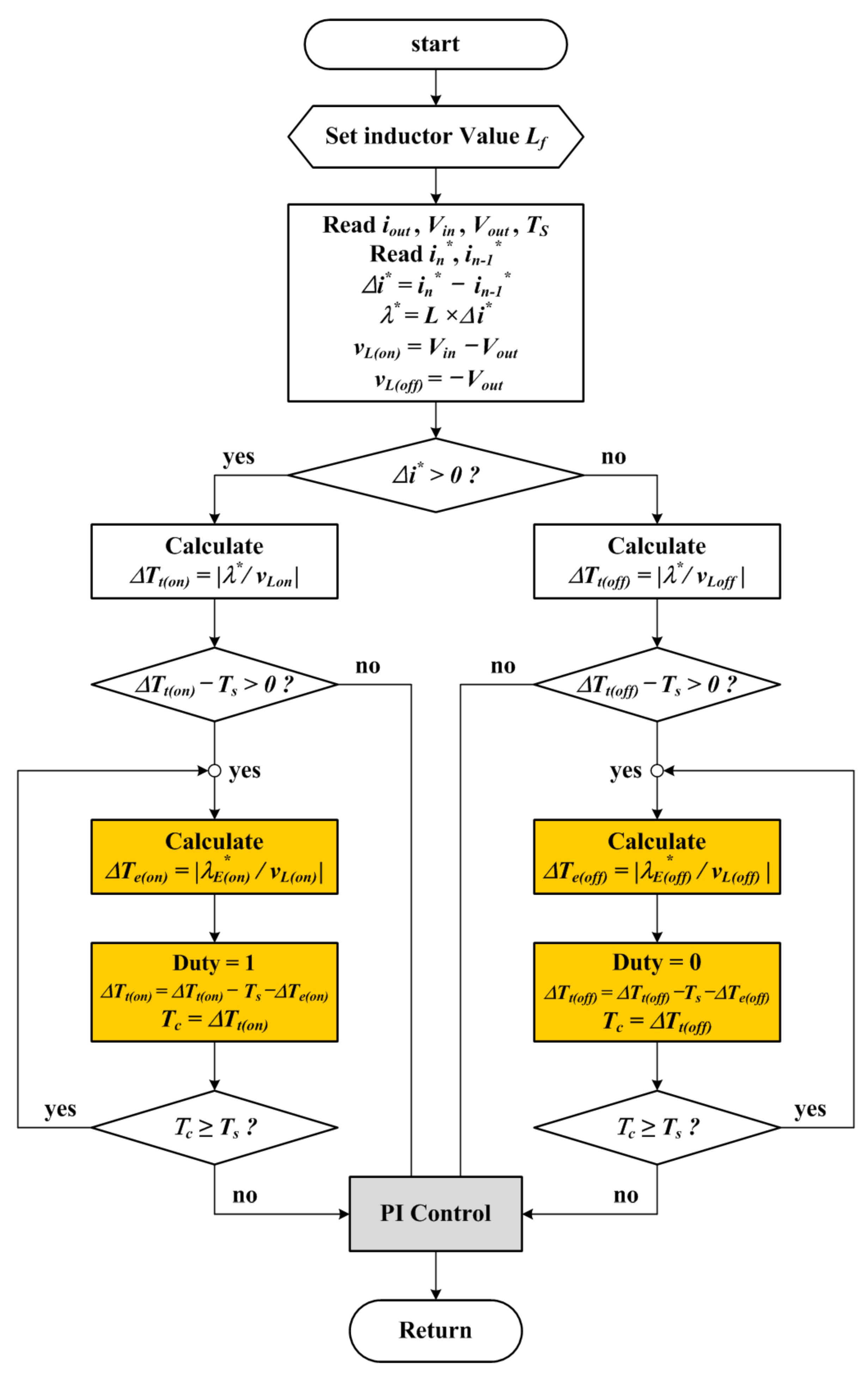
3. Enhanced Transient High-Speed Controller (ETHSC)
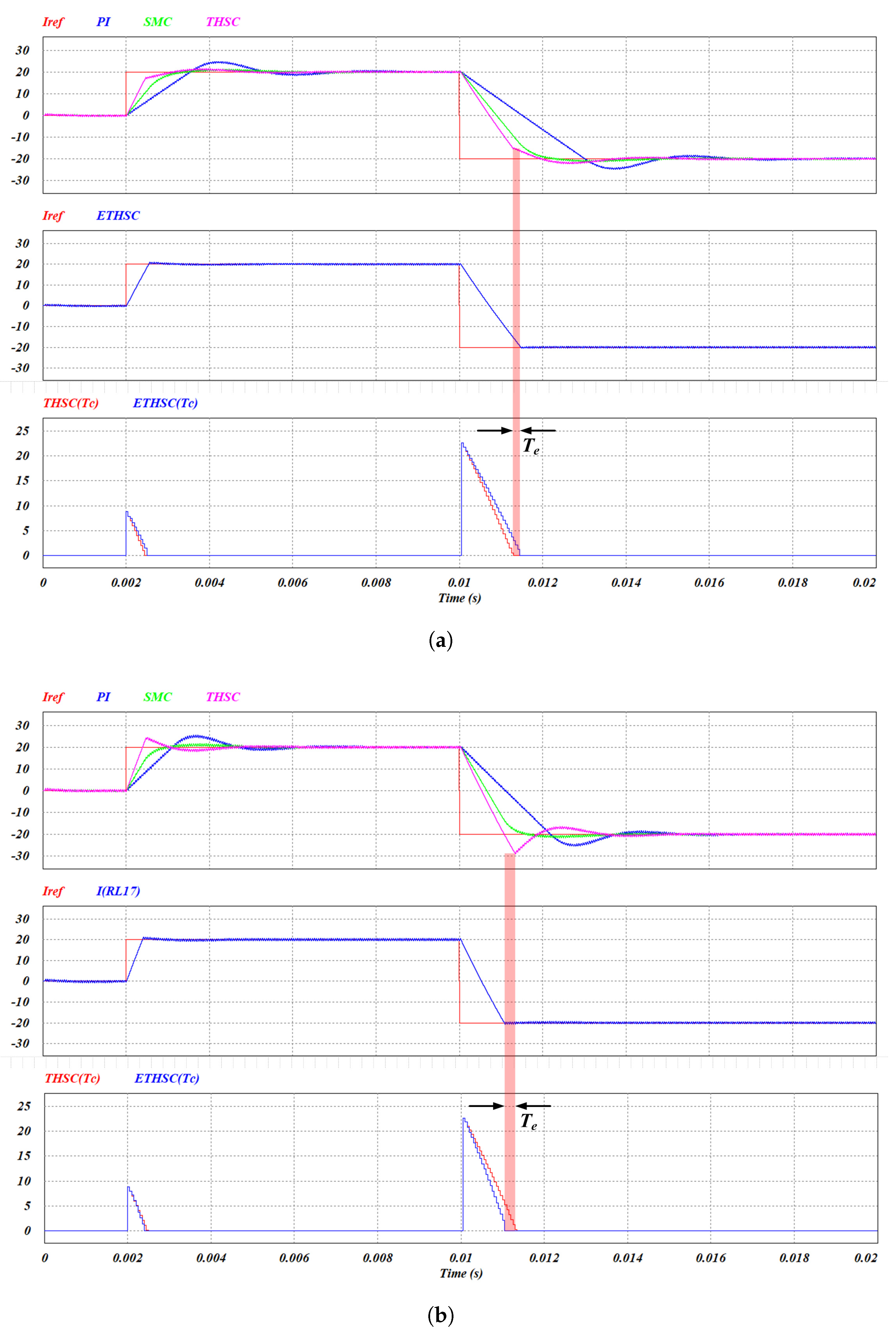
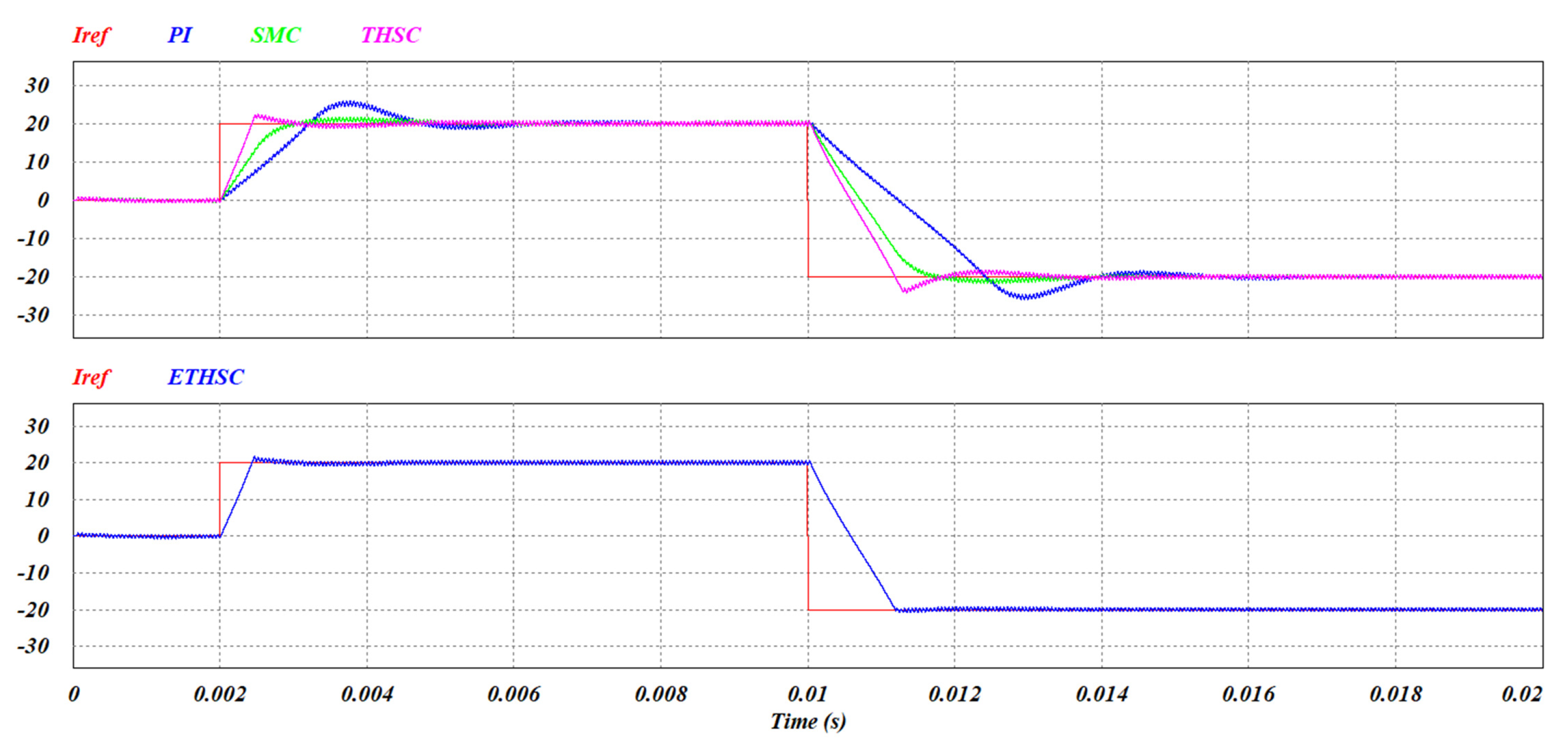
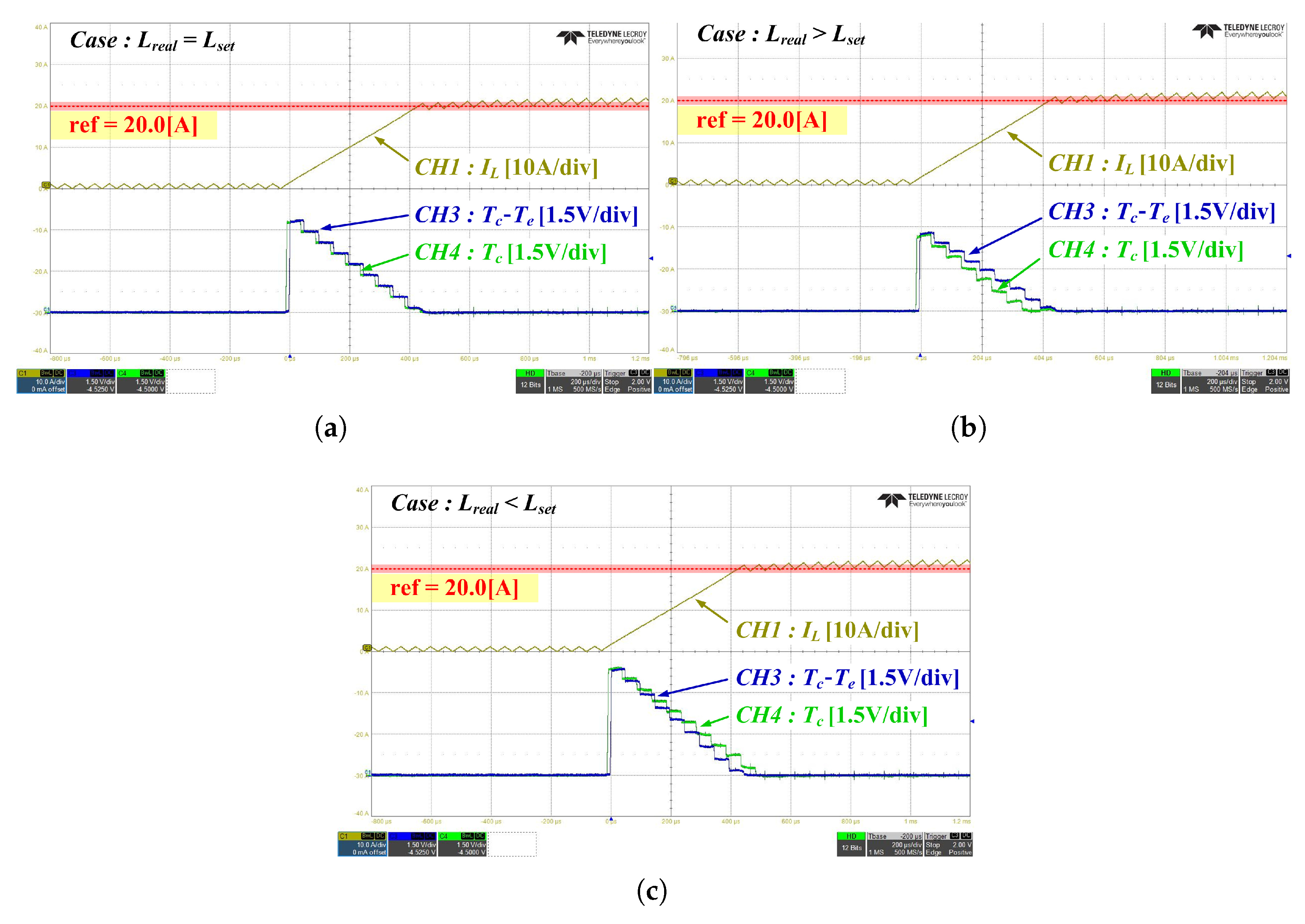
4. Simulation and Experiment
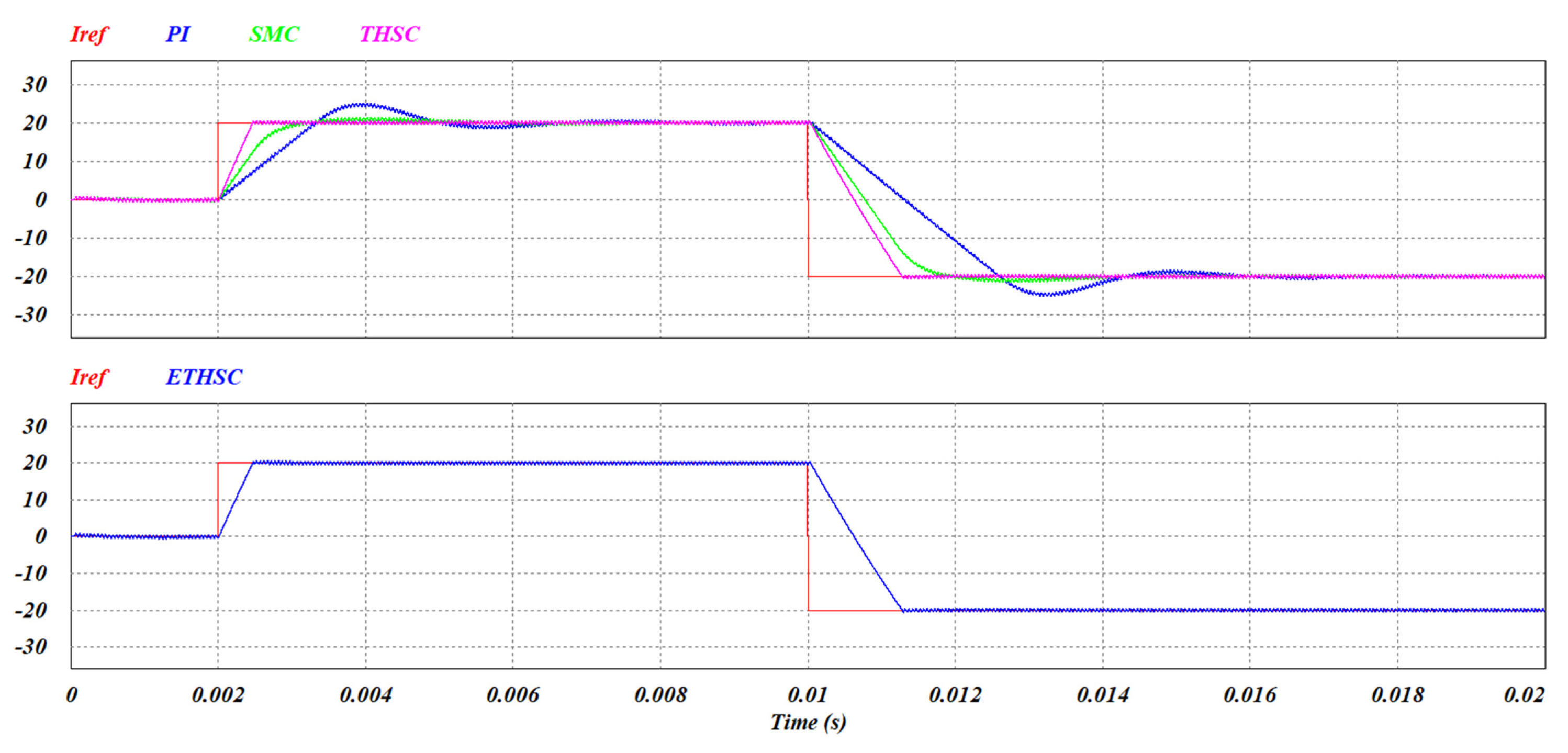
4.1. Simulation
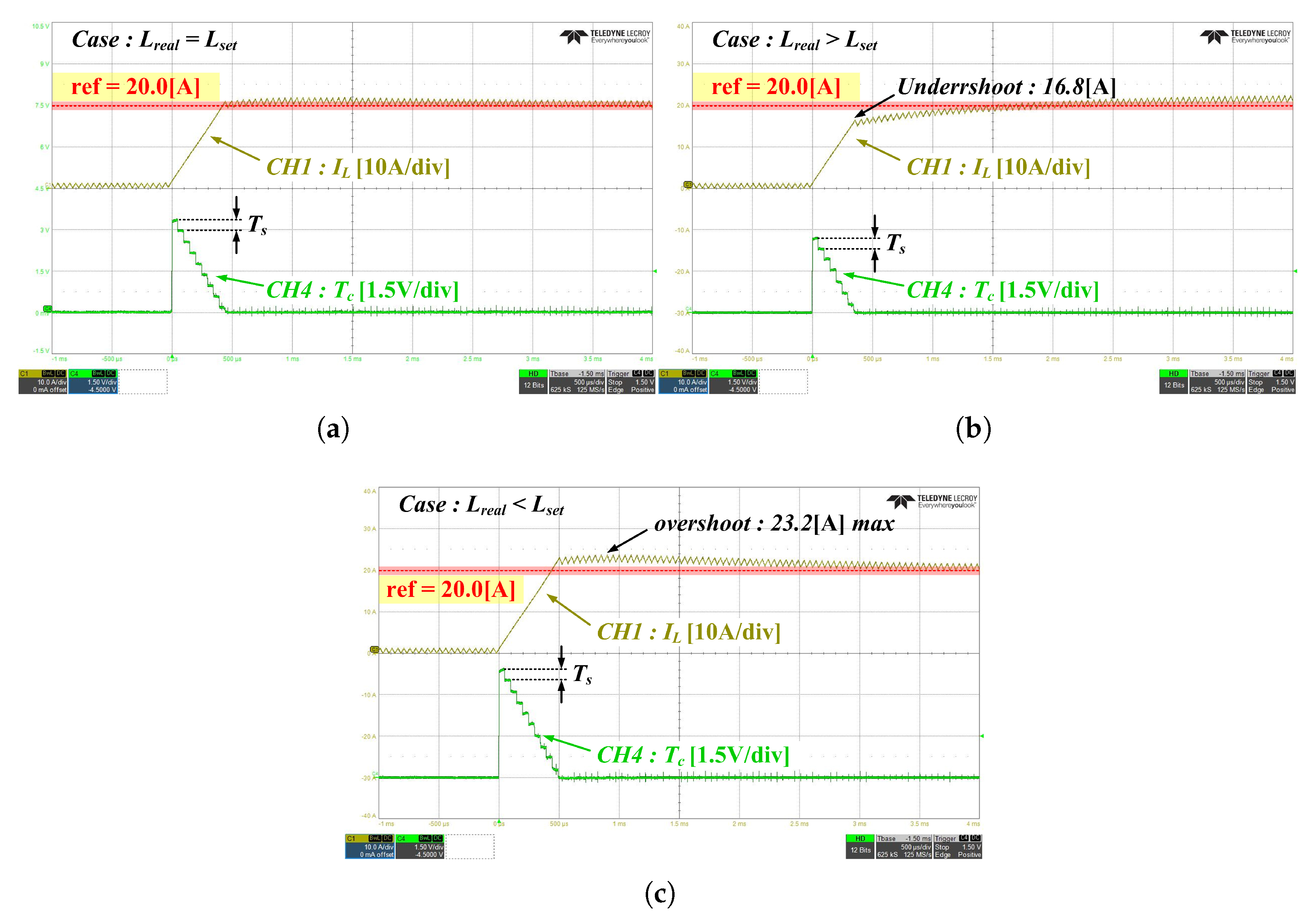
4.2. Experiment
5. Conclusions
Author Contributions
Funding
Data Availability Statement
Acknowledgments
Conflicts of Interest
References
- Shahzad, E.; Khan, A.U.; Iqbal, M.; Saeed, A.; Hafeez, G.; Waseem, A.; Albogamy, F.R.; Ullah, Z. Sensor fault-tolerant control of microgrid using robust sliding-mode observer. Sensors 2022, 22, 2524. [Google Scholar] [CrossRef]
- Javid, Z.; Kocar, I.; Holderbaum, W.; Karaagac, U. Future Distribution Networks: A Review. Energies 2024, 17, 1822. [Google Scholar] [CrossRef]
- Braco, E.; San Martín, I.; Sanchis, P.; Ursúa, A. Fast capacity and internal resistance estimation method for second-life batteries from electric vehicles. Appl. Energy 2023, 329, 120235. [Google Scholar] [CrossRef]
- Hajiaghasi, S.; Salemnia, A.; Hamzeh, M. Hybrid energy storage system for microgrids applications: A review. J. Energy Storage 2019, 21, 543–570. [Google Scholar] [CrossRef]
- Riaz, A.; Sarker, M.R.; Saad, M.H.M.; Mohamed, R. Review on comparison of different energy storage technologies used in micro-energy harvesting, WSNs, low-cost microelectronic devices: Challenges and recommendations. Sensors 2021, 21, 5041. [Google Scholar] [CrossRef]
- Ali, S.; Zheng, Z.; Aillerie, M.; Sawicki, J.P.; Pera, M.C.; Hissel, D. A review of DC Microgrid energy management systems dedicated to residential applications. Energies 2021, 14, 4308. [Google Scholar] [CrossRef]
- Aljafari, B.; Vasantharaj, S.; Indragandhi, V.; Vaibhav, R. Optimization of DC, AC, and hybrid AC/DC microgrid-based IoT systems: A review. Energies 2021, 15, 6813. [Google Scholar] [CrossRef]
- Ko, B.S.; Lee, G.Y.; Choi, K.Y.; Kim, R.Y.; Kim, S.; Cho, J.; Kim, S.I. Flexible control structure for enhancement of scalability in DC microgrids. IEEE Syst. J. 2020, 14, 4591–4601. [Google Scholar] [CrossRef]
- Mishra, M.; Patnaik, B.; Biswal, M.; Hasan, S.; Bansal, R.C. A systematic review on DC-microgrid protection and grounding techniques: Issues, challenges and future perspective. Appl. Energy 2022, 313, 118810. [Google Scholar] [CrossRef]
- Zdiri, M.A.; Dhouib, B.; Alaas, Z.; Hadj Abdallah, H. A Low-Voltage AC, Low-Voltage DC, and High-Voltage DC Power Distribution System with Grid: Design and Analysis. Appl. Sci. 2023, 13, 808. [Google Scholar] [CrossRef]
- Alsokhiry, F.; Adam, G.P. Multi-port DC-DC and DC-AC converters for large-scale integration of renewable power generation. Sustainability 2020, 12, 8440. [Google Scholar] [CrossRef]
- Mohammed, S.A.Q.; Jung, J.W. A state-of-the-art review on soft-switching techniques for DC–DC, DC–AC, AC–DC, and AC–AC power converters. IEEE Trans. Ind. Inform. 2021, 17, 6569–6582. [Google Scholar] [CrossRef]
- Neira, S.; Pereda, J.; Rojas, F. Three-port full-bridge bidirectional converter for hybrid DC/DC/AC systems. IEEE Trans. Power Electron. 2020, 35, 13077–13084. [Google Scholar] [CrossRef]
- Alamri, B.; Hossain, M.A.; Asghar, M.J. Electric power network interconnection: A review on current status, future prospects and research direction. Electronics 2021, 30, 2179. [Google Scholar]
- Jasim, A.M.; Jasim, B.H.; Neagu, B.C.; Alhasnawi, B.N. Coordination control of a hybrid AC/DC smart microgrid with online fault detection, diagnostics, and localization using artificial neural networks. Electronics 2022, 12, 187. [Google Scholar] [CrossRef]
- Amrr, S.M.; Asghar, M.J.; Ashraf, I.; Meraj, M. A comprehensive review of power flow controllers in interconnected power system networks. IEEE Access 2020, 8, 18036–18063. [Google Scholar]
- Ansari, S.; Chandel, A.; Tariq, M. A comprehensive review on power converters control and control strategies of AC/DC microgrid. IEEE Access 2020, 9, 17998–18015. [Google Scholar] [CrossRef]
- Litrán, S.P.; Durán, E.; Semião, J.; Díaz-Martín, C. Multiple-output DC–DC Converters: Applications and solutions. Electronics 2022, 11, 1258. [Google Scholar] [CrossRef]
- Hu, J.; Shan, Y.; Cheng, K.W.; Islam, S. Overview of power converter control in microgrids—Challenges, advances, and future trends. IEEE Trans. Power Electron. 2022, 37, 9907–9922. [Google Scholar] [CrossRef]
- Souza, M.E.T.; Freitas, L.C.G. Grid-connected and seamless transition modes for microgrids: An overview of control methods, operation elements, and general requirements. IEEE Access 2022, 10, 97802–97834. [Google Scholar] [CrossRef]
- Sarker, M.R.; Saad, M.H.M.; Olazagoitia, J.L.; Vinolas, J. Review of power converter impact of electromagnetic energy harvesting circuits and devices for autonomous sensor applications. Electronics 2021, 10, 1108. [Google Scholar] [CrossRef]
- Hosseinzadeh, N.; Aziz, A.; Mahmud, A.; Gargoom, A.; Rabbani, M. Voltage stability of power systems with renewable-energy inverter-based generators: A review. Electronics 2021, 10, 115. [Google Scholar] [CrossRef]
- Mancera, J.J.C.; Saenz, J.L.; López, E.; Andújar, J.M.; Manzano, F.S.; Vivas, F.J.; Isorna, F. Experimental analysis of the effects of supercapacitor banks in a renewable DC microgrid. Appl. Energy 2022, 308, 118355. [Google Scholar] [CrossRef]
- Korompili, A.; Monti, A. Review of modern control technologies for voltage regulation in DC/DC converters of DC microgrids. Energies 2023, 16, 4563. [Google Scholar] [CrossRef]
- Madurai Elavarasan, R.; Ghosh, A.; Mallick, T.K.; Krishnamurthy, A.; Saravanan, M. Investigations on performance enhancement measures of the bidirectional converter in PV–wind interconnected microgrid system. Energies 2023, 12, 2672. [Google Scholar] [CrossRef]
- Karami-Mollaee, A.; Barambones, O. Dynamic sliding mode control of dc-dc converter to extract the maximum power of photovoltaic system using dual sliding observer. Electronics 2022, 11, 2506. [Google Scholar] [CrossRef]
- Sami, I.; Alhosaini, W.; Khan, D.; Ahmed, E.M. Advancing Dual-Active-Bridge DC–DC Converters with a New Control Strategy Based on a Double Integral Super Twisting Sliding Mode Control. World Electr. Veh. J. 2024, 15, 348. [Google Scholar] [CrossRef]
- Albira, M.E.; Zohdy, M.A. Adaptive model predictive control for DC-DC power converters with parameters’ uncertainties. IEEE Access 2021, 9, 135121–135131. [Google Scholar] [CrossRef]
- Amine, H.M.; Othmane, A.; Saad, M. The impacts of control systems on hybrid energy storage systems in remote DC-Microgrid system: A comparative study between PI and super twisting sliding mode controllers. J. Energy Storage 2022, 47, 103586. [Google Scholar] [CrossRef]
- González-Castaño, C.; Restrepo, C.; Flores-Bahamonde, F.; Rodriguez, J. A composite DC–DC converter based on the versatile buck–boost topology for electric vehicle applications. Sensors 2022, 22, 5409. [Google Scholar] [CrossRef]
- Lin, H.; Cai, C.; Chen, J.; Gao, Y.; Vazquez, S.; Li, Y. Modulation and control independent dead-zone compensation for H-bridge converters: A simplified digital logic scheme. IEEE Trans. Ind. Electron. 2024, 71, 15239–15244. [Google Scholar] [CrossRef]
- Meng, X.; Zhang, Q.; Liu, Z.; Hu, G.; Liu, F.; Zhang, G. Multiple Vehicles and Traction Network Interaction System Stability Analysis and Oscillation Responsibility Identification. IEEE Trans. Power Electron. 2024, 39, 6148–6162. [Google Scholar] [CrossRef]
- Lee, J.H.; Park, S.J.; Lim, S.K. High-Speed Controller to Enhance Responsiveness and Stability of Dynamic Characteristics for DC–DC Converter. IEEE Trans. Ind. Electron. 2023, 71, 3996–4005. [Google Scholar] [CrossRef]
- Lim, S.K.; Park, S.J.; Lee, J.H. Enhanced High-Speed Controller for Dc Bus Transient Stabilization and Dynamic Stability in Electric Vehicles. Available online: https://ssrn.com/abstract=4620840 (accessed on 2 November 2023).


| Controller Type | Advantages | Limitations |
|---|---|---|
| PCMC | Simple design | Bandwidth limitation, sub-harmonic oscillation |
| SMC | Robust performance | Complex design, computational burden |
| THSC | Fast transient response | Open-loop, parameter dependency leads to overshoot/undershoot |
| ETHSC (Proposed) | Fast transient response, real-time error correction | Additional computational step for correction |
| Note | Symbol | Value |
|---|---|---|
| Converter input voltage | 24 V | |
| Battery voltage | 48 V | |
| Inductor set value | 620 ± 100 H | |
| Inductor value in simulation circuit | 620 H | |
| Actual inductor value | Figure 9b data | |
| Max. current command value variation | 20.0 A | |
| System requirements’ response time | 600 s | |
| Switching frequency | 20 kHz |
| Test Condition | Controller | Rising Time | Falling Time | Deviation (R/F) |
|---|---|---|---|---|
| PI | 1.3 ms | 2.6 ms | 4.7 A/4.7 A | |
| SMC | 1.2 ms | 1.8 ms | 0.9 A/0.9 A | |
| THSC | 516 s | 1.03 ms | 2.5 A/4.1 A | |
| ETHSC | 516 s | 1.03 ms | 0.3 A/0.2 A | |
| PI | 1.5 ms | 3.0 ms | 4.5 A/4.5 A | |
| SMC | 1.3 ms | 2.2 ms | 0.8 A/0.8 A | |
| THSC | 1.1 ms | 1.8 ms | 1.0 A/1.7 A | |
| ETHSC | 751 s | 1.5 ms | 0.2 A/0.1 A | |
| PI | 1.1 ms | 2.2 ms | 5.1 A/5.1 A | |
| SMC | 975 s | 1.6 ms | 0.9 A/0.9 A | |
| THSC | 500 s | 1.0 ms | 4.0 A/8.5 A | |
| ETHSC | 500 s | 1.0 ms | 0.2 A/0.1 A | |
| nonlinear L | PI | 1.2 ms | 2.4 ms | 5.3 A/5.3 A |
| SMC | 960 s | 1.9 ms | 0.9 A/0.9 A | |
| THSC | 432 s | 1.2 ms | 2.5 A/4.1 A | |
| ETHSC | 432 s | 1.2 ms | 0.4 A/0.2 A |
| Note | Symbol | Value |
|---|---|---|
| Converter input voltage | 22.4 to 29.2 V | |
| Battery voltage | 44.8 to 58.4 V | |
| System inductor’s inductance | 620 H | |
| Inductance | 620 ± 100 H | |
| Max. current command value variation | 20.0 A | |
| System requirements response time | 600 s | |
| Switching frequency | 20 kHz | |
| System P gain | 0.003 | |
| System I gain | 1.2 |
| Test Condition | Controller | Arrival Time | Deviation Value |
|---|---|---|---|
| THSC | 467 s | +0.1 A | |
| ETHSC | 452 s | −0.1 A | |
| THSC | 1.5 ms | −3.2 A | |
| ETHSC | 453 s | +0.1 A | |
| THSC | 467 s | +3.2 A | |
| ETHSC | 455 s | +0.1 A |
Disclaimer/Publisher’s Note: The statements, opinions and data contained in all publications are solely those of the individual author(s) and contributor(s) and not of MDPI and/or the editor(s). MDPI and/or the editor(s) disclaim responsibility for any injury to people or property resulting from any ideas, methods, instructions or products referred to in the content. |
© 2025 by the authors. Licensee MDPI, Basel, Switzerland. This article is an open access article distributed under the terms and conditions of the Creative Commons Attribution (CC BY) license (https://creativecommons.org/licenses/by/4.0/).
Share and Cite
Lim, S.-K.; Park, S.-J.; Lee, J.-H. A Study on Novel Current Controller for Improving Transient Characteristics in Direct Current Power Systems. Electronics 2025, 14, 881. https://doi.org/10.3390/electronics14050881
Lim S-K, Park S-J, Lee J-H. A Study on Novel Current Controller for Improving Transient Characteristics in Direct Current Power Systems. Electronics. 2025; 14(5):881. https://doi.org/10.3390/electronics14050881
Chicago/Turabian StyleLim, Sang-Kil, Sung-Jun Park, and Jung-Hwan Lee. 2025. "A Study on Novel Current Controller for Improving Transient Characteristics in Direct Current Power Systems" Electronics 14, no. 5: 881. https://doi.org/10.3390/electronics14050881
APA StyleLim, S.-K., Park, S.-J., & Lee, J.-H. (2025). A Study on Novel Current Controller for Improving Transient Characteristics in Direct Current Power Systems. Electronics, 14(5), 881. https://doi.org/10.3390/electronics14050881