Article

A Comparative Analysis of Fuzzy Logic Control and Model Predictive Control in Photovoltaic Maximum Power Point Tracking

Department of Electrical, Computer, and Software Engineering, The University of Auckland, Auckland 1010, New Zealand
*
Author to whom correspondence should be addressed.
Electronics 2025, 14(5), 1009; https://doi.org/10.3390/electronics14051009
Submission received: 21 January 2025 / Revised: 19 February 2025 / Accepted: 27 February 2025 / Published: 3 March 2025

Abstract

:
Operating PV panels at the Maximum Power Point (MPP) is crucial for increasing efficiency and reducing the payback period of the system. However, the voltage and current characteristics of PV panels are nonlinear and depend on environmental conditions like temperature and irradiance. This paper presents a comparative analysis of Fuzzy Logic Control (FLC) and Model Predictive Control (MPC) for Maximum Power Point Tracking (MPPT) applied to a photovoltaic generation system. The study focuses on FLC due to its rapid response and robustness against circuit parameter variations. MPC, known for its predictive capabilities, is also investigated for comparison. A PI control strategy is employed to maintain the desired current and voltage during battery charging. The results show that, under standard test conditions (1000 W/m2 irradiance and 25 °C temperature), the FLC-based MPPT achieved an average efficiency of 98.298%, with a response time of 12 ms. In comparison, the MPC-based MPPT achieved 96.598% efficiency and a 25 ms response time. During dynamic irradiance changes, FLC demonstrated faster adaptation with a peak tracking error of 2.398%, while MPC had a tracking error of 4.598%. These findings highlight the superior dynamic performance of FLC in real-time PV tracking and the stability of MPC for long-term optimization.

1. Introduction

As the global demand for renewable energy escalates, photovoltaic (PV) systems play a pivotal role in advancing sustainable energy solutions. However, the efficiency of PV systems is inherently constrained by the nonlinear characteristics of PV panels, which are highly sensitive to environmental conditions such as temperature and irradiance [1,2,3]. Evaluating the effects of irradiance and temperature variations is crucial in assessing PV system performance. Rapid changes in irradiance, such as those caused by passing clouds, present a challenge for Maximum Power Point Tracking (MPPT) algorithms by inducing fluctuations in power output. Conversely, slower temperature variations affect the voltage characteristics of PV panels and can shift the Maximum Power Point (MPP). Both factors play a critical role in determining tracking accuracy and system efficiency over time [4]. Thus, these factors significantly impact the maximum power output achievable, making it essential to operate PV systems at their MPP under varying conditions [5,6].
To maximize the power output from PV systems, various MPPT techniques have been developed. Traditional MPPT strategies, such as Perturb and Observe (P&O), are widely adopted due to their simplicity, ease of implementation, and low computational requirements. These advantages make P&O a cost-effective solution, particularly for systems with limited resources or where precision is less critical. However, despite these benefits, P&O suffers from several limitations, including oscillations around the Maximum Power Point (MPP) during steady-state operation and slow response to rapid environmental changes [7]. These issues reduce energy conversion efficiency and limit the method’s effectiveness under dynamic conditions. These limitations are particularly problematic under rapidly changing environmental conditions, where a slow response and power fluctuations significantly reduce system efficiency and stability. Short-term photovoltaic power prediction based on meteorological reconstruction has been proposed as an effective strategy to address fluctuations in power generation caused by environmental variability [8,9]. This approach enhances power management by enabling more accurate forecasting and optimization of MPPT control in real-time operations. Additionally, a novel multiple-medium AC-port power electronic transformer has been introduced to improve the efficiency and flexibility of energy conversion in PV systems [10,11]. This design enhances power distribution by supporting multiple grid interfaces, thereby ensuring stable integration of renewable energy sources. Another innovative solution is the asymmetric hybrid phase-leg modular multilevel converter, which offers a compact, cost-effective design with DC fault-blocking capability [12]. This converter improves system stability and resilience in high-power applications, ensuring continuous operation under fault conditions [12,13]. Given the growing need for robust MPPT control to optimize energy conversion and extend battery lifespan, this study aims to develop a control strategy that ensures both a rapid dynamic response and steady-state accuracy under varying operating conditions. Advanced techniques, such as Model Predictive Control (MPC) and Fuzzy Logic Control (FLC), overcome these limitations by offering faster dynamic response, higher accuracy, and improved robustness, thereby ensuring more reliable and efficient power tracking in varying environments [7].
Model Predictive Control (MPC) has emerged as a robust MPPT technique, celebrated for its predictive capabilities and effectiveness in managing multi-variable control challenges [14,15]. By optimizing control actions over a future time horizon, MPC delivers superior transient and steady-state performance [16,17]. Similarly, Fuzzy Logic Control (FLC) has been widely applied in MPPT systems due to its adaptive control capabilities and ability to manage system uncertainties without requiring precise mathematical models. However, FLC may exhibit transient oscillations under rapidly changing environmental conditions. Despite these advancements, integrating MPPT techniques with efficient battery management systems remains a critical research focus. Effective battery charging strategies are essential to ensure the longevity and reliability of energy storage solutions [18,19]. Combining MPPT with robust charge control mechanisms, such as those provided by PI controllers in buck converters, significantly improves both the energy conversion efficiency and battery life cycle. As renewable energy systems grow in complexity and scale, the need for comprehensive solutions addressing both power generation and storage has never been greater [20,21].
To address the aforementioned limitations, this study distinguishes itself by integrating the MPPT controller, namely MPC and FLC, with a specific focus on battery safety current management. While the traditional methods mainly emphasize tracking accuracy, this work adopts a more holistic approach by balancing dynamic performance and safe energy storage. The proposed hybrid strategy leverages MPC’s predictive control and FLC’s adaptive handling of nonlinearities, ensuring improved response time, tracking stability, and robustness to environmental variations. Additionally, this study explicitly mitigates overcurrent and overcharging risks, often overlooked in prior research, by incorporating a PI-regulated buck converter to provide safe and efficient battery charging. Thus, this study aims to compare the dynamic response, steady-state accuracy, and computational complexity of FLC and MPC under varying environmental conditions. This is achieved by optimizing the energy conversion efficiency of PV panels to ensure consistent operation at the MPP and to enable reliable and efficient battery charging through the integration of a PI-controlled buck converter. The effectiveness of FLC and MPC are also compared with that of P&O [22,23] to investigate the capabilities of advanced control techniques to address the growing complexity and demands of modern PV systems [24,25]. Unlike prior studies, which often overlook overcurrent and overcharging risks, this work emphasizes enhanced system efficiency, stability, and prolonged battery lifespan through precise control mechanisms [26,27]. The PI regulator was chosen based on its wide acceptance and suitability for real-time control in resource-constrained systems, particularly where the computational cost of more advanced methods might be prohibitive [27,28,29].
The key contributions include a comparative performance analysis of FLC and MPC, an evaluation of how computational complexity affects real-time implementation, and recommendations on selecting appropriate control strategies based on the system resources. It hypothesizes that MPC outperforms FLC in dynamic performance but that FLC is better suited for resource-constrained systems due to the lower computational requirements. By providing valuable insights into the practical implementation of these control strategies, this research contributes to the ongoing development of renewable energy technologies and cost-effective, scalable solutions for PV systems.
This paper is structured as follows: Section 1 introduces the system’s control objectives and constraints. Section 2 presents the problem formulation, describing the system’s operation, including the key stages of MPPT and battery charging control. The designs of Fuzzy Logic Control (FLC) and Model Predictive Control (MPC) are explained in Section 3 and Section 4. Section 5 evaluates both strategies’ dynamic and steady-state performance under varying environmental conditions. Section 6 provides key insights, limitations, and implications, while Section 7 summarizes the findings and contributions of this study.

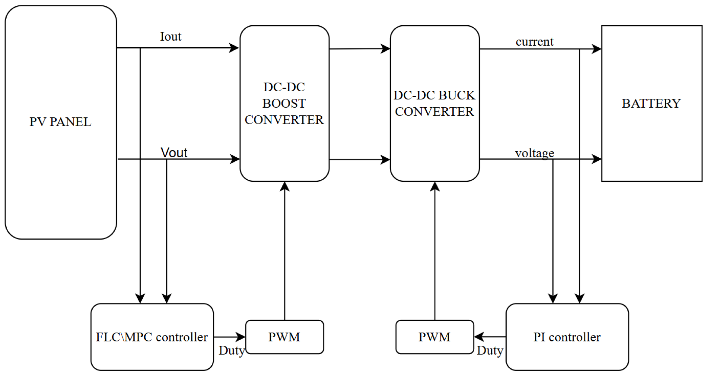
2. Problem Formulation

In the system illustrated in Figure 1, the control of power flow from the PV panel to the battery involves two main stages: MPPT to maximize the power harvested from the PV panel and battery charging control to ensure efficient and safe energy storage. The study utilizes a standard photovoltaic (PV) panel model to simulate system performance under varying environmental conditions, focusing on collaborative use of different control strategies, and the integration of a PI-controlled buck converter for stable and safe charging. The system can operate under two different control strategies, namely FLC and MPC. In this study, a PI controller was chosen to regulate the buck converter for constant current and constant voltage battery charging. PI controller is favored for their ease of implementation, stable performance, and minimal computational requirements, which make them ideal for resource-constrained systems [6]. This choice is motivated by the PI controller’s ability to ensure safe current and voltage regulation, thereby mitigating risks such as overcharging and thermal runaway during battery operation. The simplicity, reliability, and real-time suitability of PI controller overweigh the other control methods. For instance, Sliding Mode Control (SMC) offers fast dynamic response but may introduce chattering effects that complicate implementation and increase switching losses [1]. H control effectively handles disturbances but requires complex modeling and high computational demand, which may hinder its feasibility for real-time PV applications [2]. Lyapunov-based control ensures global stability but often involves conservative tuning parameters, limiting its dynamic performance potential [3]. Adaptive control dynamically adjusts to parameter changes but increases system complexity through continuous estimation [6]. In contrast, the PI regulator achieves an optimal balance between stability, computational efficiency, and dynamic performance, making it suitable for PV-battery systems that prioritize safety, simplicity, and reliable operation. These features make the PI controller an ideal choice for achieving efficient, reliable, and cost-effective battery charging in photovoltaic systems.
The PV module is modeled to generate electrical power based on input irradiance (in W/m2) and temperature (in °C), with the electrical characteristics being shown in Table 1. These environmental parameters directly affect the current and voltage output of the PV array, with the nominal values being 1000 W/m2 and 25 °C. In the Simulink model, the PV module block takes inputs of irradiance and temperature to simulate the real-time power generation characteristics. The governing equation of the PV module is provided by
I out = I sc I D
I D = I 0 e q ( V + I R s ) n K T 1
where I out ,   I sc ,   I D ,   I 0 are the output current, short-circuit current, diode current, and saturation current, respectively, while V ,   q ,   R s ,   n ,   K ,   T are, respectively, terminal voltage, electron charge constant, series resistance, ideality factor, Boltzmann constant, and absolute temperature.
In the context of photovoltaic array regulation, FLC employs an MPPT controller that processes voltage and current inputs through fuzzy inference rules, effectively addressing system nonlinearities and uncertainties to refine the PWM generator’s duty cycle. Meanwhile, the MPC framework utilizes a predictive model to optimize control actions over a designated time horizon, determining the optimal duty cycle via an optimization problem to sustain operation at the Maximum Power Point while respecting system constraints.
The DC–DC boost converter increases the PV panel voltage according to the duty cycle determined by the MPPT controller (FLC or MPC). Figure 2 illustrates the buck converter structure, where the MOSFET, inductor, diode, and capacitor regulate V in to achieve the desired V out . The design parameters in Table 2 were derived based on PV panel characteristics (Table 1) to ensure efficient power conversion and stable battery charging.
The inductor (L) and capacitor (C) values were calculated using the following equations:
L = ( V in V out ) D Δ I L f s , C = I out D f s Δ V out
where V in and V out are, respectively, the input and output voltage, D is the duty cycle, Δ I L is the allowable current ripple (typically 20–40% of I mpp ), f s denotes the switching frequency, I out is the load current, and Δ V out is the allowed output voltage ripple (typically 1–5% of V out ). Given the nominal values from Table 1 and switching frequency of 50 kHz, the commercially available L and C are, respectively, 100 μH and 470 μF. Meanwhile, the MOSFET and diode ratings of 50 V are selected to ensure a sufficient safety margin relative to the maximum operating voltage.
From Equation (3), modifying parameter values significantly impacts system behavior. Increasing L reduces current ripple, which results in smoother current flowing through the load. However, higher L leads to slower transient response to load changes. Conversely, decreasing L causes a more prominent current ripple. Yet, lower L improves the transient response, enabling the system to react more quickly to sudden changes. Increasing C provides smoother output voltage ripple, which helps to ensure a stable output voltage. However, a larger capacitance also leads to a slower transient response because the capacitor takes longer to charge and discharge. Such trade-off between ripple suppression and responsiveness must be considered in PV-battery charging applications.
The battery charge unit in the diagram highlights that the converter is part of a larger power management system where the buck converter stabilizes the voltage for energy storage. The PI controller is employed to regulate the output voltage ( V out ) by comparing the reference voltage ( V ref ) with the actual output voltage, and its gains ( K p and K i ) were dimensioned through simulations to ensure a balance between steady-state accuracy, dynamic performance, and system stability. Regarding the dimensioning of the PI control, the proportional and integral gains were determined using a systematic tuning process. Initially, the Ziegler–Nichols tuning method was applied to estimate the parameters. The gains were then iteratively fine-tuned through simulation to achieve optimal performance, balancing transient response and steady-state accuracy. This approach ensured the stability of the system while minimizing steady-state errors and oscillations. The error signal is processed by the proportional ( K p ) and integral ( K i ) control blocks to generate the necessary control signal, which adjusts the duty cycle of the buck converter. This system ensures steady-state error minimization and improved dynamic performance.
Key control parameters were iteratively adjusted to ensure optimal system performance. The MPC prediction horizon and weighting factors were tuned to balance response time and computational complexity. For FLC, membership functions and rule bases were optimized to enhance tracking accuracy under nonlinear system conditions. Additionally, the PI gains of the buck converter were adjusted to maintain stable voltage regulation, minimizing both steady-state and transient fluctuations. These adjustments enabled consistent performance across varying irradiance and temperature levels. To ensure a fair comparison, the FLC, MPC, and PI controllers were implemented with identical system parameters and under the same environmental conditions. The performance of each controller was evaluated based on tracking accuracy, dynamic response time, and steady-state oscillations. The PI controller’s proportional and integral gains were selected using the Ziegler–Nichols method, providing a balance between response time and stability. The FLC and MPC controllers were tuned to minimize tracking error and ensure fast convergence to the Maximum Power Point (MPP). The performance comparison showed that both FLC and MPC significantly outperformed traditional PI in terms of faster response time and improved efficiency. The proposed methods maintained low steady-state oscillations and tracked the MPP more accurately compared to the PI controller.

3. Design of FLC

FLC is extensively utilized in photovoltaic (PV) systems for MPPT owing to its effectiveness in managing the nonlinearities and uncertainties characteristic of such systems. By employing heuristic rules derived from expert knowledge rather than requiring precise mathematical modeling, FLC adeptly adapts to fluctuating environmental conditions. The implementation of FLC involves designing the fuzzy system, tuning the membership functions and rules, and integrating the controller into the system. The Fuzzy Logic Controller (FLC) applies a rule base that governs the relationship between input variables—error (E) and change in error ( C E )—and the output duty cycle (D). These rules, shown in Table 3, were developed based on expert knowledge and performance tuning through simulation. No artificial intelligence (AI) methods were used in the initial design or optimization of the rules [26].

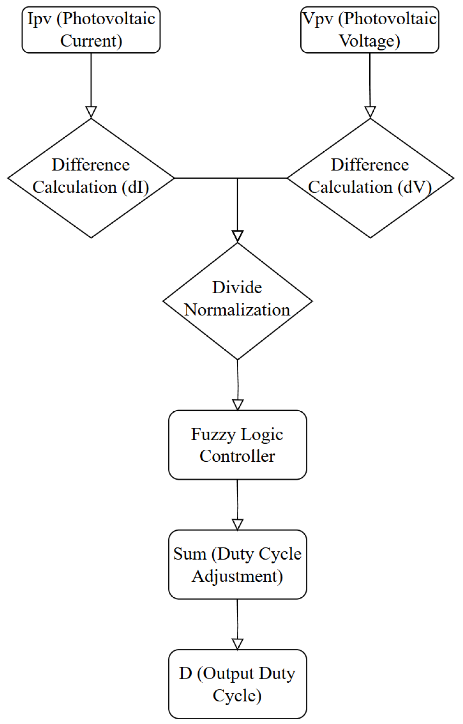
3.1. Define Inputs and Outputs
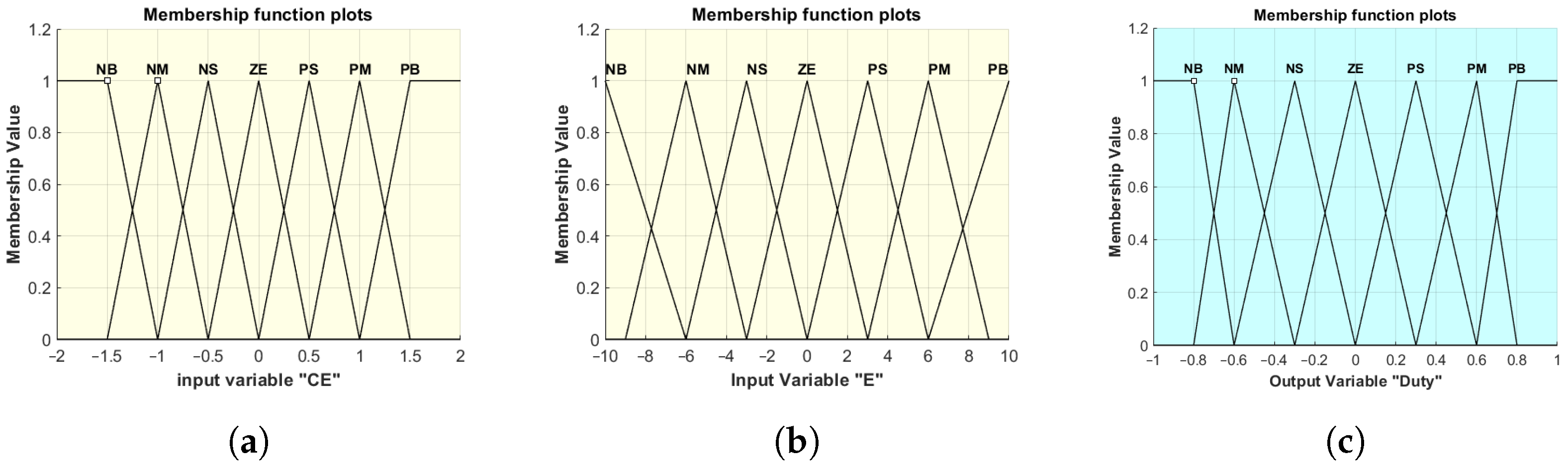
The control strategy is centered around the calculation of the error E ( k ) and the change in error C E ( k ) as the input variables, as expressed by the following equations:
E ( k ) = Δ P Δ V = P ( k ) P ( k 1 ) V ( k ) V ( k 1 ) C E ( k ) = E ( k ) E ( k 1 )
where P represents the output power (in watts) and V represents the output voltage (in volts). The variable E ( k ) denotes the error at time step k, reflecting the ratio of power change to voltage change. These input variables are processed through membership functions that assign linguistic variables to values, facilitating fuzzy control logic.

3.2. Fuzzification

Design membership functions to map crisp inputs into fuzzy sets. Membership functions can be triangular, trapezoidal, or Gaussian. Figure 3a,b represent the fuzzified inputs, and Figure 3c depicts the output.

3.3. Fuzzy Rule Base

The fuzzy rule table in Table 3 represents the decision-making logic of the Fuzzy Logic Controller (FLC). It defines the relationship between two input variables−error (E) and change in error ( C E )−and the output variable, which determines the adjustment to the duty cycle (D).
The table’s rows correspond to the linguistic values of C E , while the columns correspond to the linguistic values of E. The entries in the table specify the output fuzzy set for D, represented by linguistic terms such as positive big (PB), positive medium (PM), zero (ZE), negative medium (NM), and negative big (NB). These linguistic terms define the magnitude and direction of the duty cycle adjustment required to maintain optimal performance.
The Fuzzy Logic Controller in this study uses triangular membership functions for E, C E , and D, with each having seven linguistic terms (NB, NM, NS, ZE, PS, PM, and PB), as shown in Figure 3a–c. The design employs evenly spaced membership functions, developed through expert knowledge and performance tuning. While effective, this design does not involve a formal optimization process. The granularity of these functions affects performance by influencing both control precision and computational complexity. Finer granularity improves control precision but may increase oscillations and computational load, which is critical in real-time applications.
For instance, when E is positive big (PB) and C E is zero (ZE), the output D may be negative big (NB), indicating a large reduction in the duty cycle. Similarly, when E is negative small (NS) and C E is negative small (NS), the output D may remain zero (ZE), meaning no adjustment is needed. This rule base enables the FLC to handle nonlinear and uncertain conditions effectively. It operates by fuzzifying the crisp inputs into linguistic terms, applying the rules defined in the table, and defuzzifying the results into a crisp output. The membership functions shown in Figure 3a–c illustrate the mapping of crisp variables into fuzzy sets and vice versa.

3.4. Integration

The fuzzy inference system processes normalized error and change in error derived from the photovoltaic current ( I p v ) and voltage ( V p v ), adjusting the DC–DC converter’s duty cycle (D) to maximize power output. Figure 4 illustrates the FLC-based MPPT system. In the FLC, the control signal is often represented by a duty cycle, which is defined as the ratio of the “on” time to the total period of a periodic signal. The duty cycle is typically expressed as a percentage (%). This ratio determines the output intensity or control action, such as the speed of a motor or the heating power in a temperature control system. The duty cycle does not have physical units, but it is expressed in percentage to indicate the proportion of time the control signal is active during a cycle.

3.5. Tuning

Tuning the FLC involves adjusting the shape and position of the membership functions, as well as fine-tuning the rules for optimal performance. This tuning is often conducted iteratively based on system response, aiming to improve stability and reduce steady-state error.
  • Membership Functions: Adjust the range and overlap of the membership functions to handle system dynamics better.
  • Rule Adjustment: Modify or add new rules based on how the system responds to different conditions.

4. Design of MPC

Model Predictive Control (MPC) offers a more advanced approach for managing MPPT in PV systems, utilizing a predictive model to forecast future system behavior and optimize control inputs. The MPC controller optimizes control actions using a predictive model. The study uses a full-order model, but future work could explore simplification to improve real-time efficiency. Unlike FLC, which relies on rule-based adjustments, MPC solves an optimization problem at each sampling interval to determine the optimal duty cycle for the DC–DC converter. The MPC controller aims to minimize the following objective function:
J = k = 0 N 1 V d c ( k ) V d c ref P + V P V ( k ) V P V ref R + λ Δ u F
where y ref ( k + i ) represents the reference signal (desired system output), y ( k + i ) is the predicted system output, Δ u ( k + i ) is the change in control input, and λ is the weight balancing tracking performance and control effort. This function ensures real-time optimization while maintaining computational efficiency within system constraints.

4.1. Handling Constraints

MPC directly incorporates system constraints into the optimization problem, ensuring that control actions remain within physical limits. This includes the following:
  • Input constraints (i.e., voltage):
    30 V u ( k ) 500 V
  • State constraints (i.e., temperature):
    25   ° C x ( k ) 60   ° C
  • Output constraints (i.e., power):
    0 W y ( k ) 500 W
These constraints are critical in ensuring that the system operates safely while optimizing performance.

4.2. Efficient Code and Solver Optimization

To ensure real-time performance, the following strategies are employed:
  • Use efficient numerical solvers (e.g., active-set or interior-point methods) that can solve the optimization problem within the control cycle time.
  • Reduce prediction horizons if computational time becomes a limiting factor.
  • Optimize the code by minimizing unnecessary calculations and using parallel computing if necessary to improve the processing speed.

5. Results and Analysis

5.1. Performance Comparison

5.1.1. Dynamic Response Characteristics

In terms of dynamic response, FLC (Figure 5) demonstrates a rapid initial response but with pronounced oscillations and slow settling times, indicating its limitations in handling dynamic changes effectively. In contrast, MPC (Figure 6) provides a smoother dynamic response with a quicker approach to the setpoint. However, the presence of high-frequency oscillations highlights its sensitivity to rapid changes. It is worth noting that “duty” in the figures indicates a dimensionless quantity representing the ratio of on-time to the total switching period, which directly influences the voltage and current regulation in the system.
As shown in Figure 7, the combined FLC and PI controller provides a rapid dynamic response during the rising phase from 0 s to 0.05 s , reaching a near steady-state current value of approximately 160 mA to 180 mA . The rise time is short, with no significant overshoot, and, after 0.1 s , the current stabilizes with minimal oscillation and negligible steady-state error.
In contrast, Figure 8 illustrates that the combined MPC and PI strategy offers even better dynamic performance. The current rises rapidly to the setpoint with minimal overshoot and transitions smoothly to the steady state. This demonstrates the effectiveness of combining predictive control (MPC) with traditional PI control to enhance both transient and steady-state performance. While the dynamic response is demonstrated, further stability analysis and disturbance rejection tests are necessary to ensure robustness [22]. The modal analysis of the closed-loop system has shown that the closed-loop poles are negative real numbers, indicating that the system is stable under MPC control. This stability ensures that the system can effectively reject disturbances and maintain performance during transient conditions.
The current rises sharply during the initial transient phase, with the FLC-PI and MPC-PI controllers achieving steady-state performance rapidly and efficiently. Both controllers excel in achieving steady-state performance with negligible oscillations and zero steady-state error. However, as shown in Figure 8, the MPC-PI controller demonstrates faster transient performance than FLC-PI during the initial phase, with a quicker rise to the target value and minimal overshoot. In contrast, Figure 7 shows that the FLC-PI controller, while slightly slower, also stabilizes efficiently with no steady-state error. The FLC-PI and MPC-PI controllers exhibit stable steady-state values with negligible oscillations and zero steady-state error. These characteristics demonstrate their superior performance in achieving precision and minimizing power losses while maintaining high efficiency.
The comparative analysis of the controllers highlights their respective strengths and limitations. The MPC-PI controller demonstrates the best transient performance, with the fastest rise time and minimal overshoot. FLC-PI also offers a rapid rise but is slightly slower than MPC-PI. In contrast, the FLC-PI and MPC-PI controllers achieve stable steady-state values with negligible oscillations and zero steady-state error. Regarding steady-state stability, both the FLC-PI and MPC-PI controllers demonstrate superior performance in achieving precision and minimal steady-state error. In terms of suitability, FLC-PI and MPC-PI are ideal for systems requiring precision and minimal steady-state error, making them efficient and reliable choices for complex systems.

5.1.2. Performance Under Different Disturbances

Figure 5 and Figure 6 illustrate the robustness of FLC and MPC under disturbances such as load variations and input fluctuations. FLC, as shown in Figure 5, exhibits significant oscillations under disturbances, reflecting its limited ability to adapt to sudden changes due to the static nature of its rule-based control, which lacks predictive capability. MPC, depicted in Figure 6, mitigates disturbances more effectively by adjusting the control inputs based on predicted future states. However, high-frequency oscillations under certain conditions suggest that further optimization in model accuracy or control frequency may enhance disturbance rejection. The hybrid MPC+PI control approach (Figure 8) demonstrates improved robustness by stabilizing the current more quickly after disturbances, leveraging MPC’s predictive control and PI’s error correction capabilities to ensure a more stable response. Meanwhile, the FLC+PI controller (Figure 9) exhibits substantial voltage oscillations between 0 V and 15 V, indicating a periodic steady-state response rather than a stable output. These oscillations may stem from inadequate tuning or under-damping, potentially impacting the system performance despite maintaining a stable amplitude. In contrast, the MPC+PI controller (Figure 10) demonstrates larger oscillations (4 V to 16 V) and a slower dynamic response, revealing a trade-off between transient and steady-state performance. While MPC enhances predictive accuracy, its performance may be compromised by PI-induced delays.
The simulation results confirm that the proposed methods significantly improve both tracking accuracy and dynamic response under varying environmental conditions. For instance, under standard test conditions (1000 W/m2 irradiance and 25 °C temperature), the FLC-based MPPT achieved a simulated response time of 12 ms and an efficiency of 98.298%. In comparison, the MPC-based approach demonstrated smoother transient performance, effectively stabilizing power tracking during rapid irradiance fluctuations in the simulation environment.

5.2. Computational Complexity

MPC requires solving an optimization problem at each sampling interval, resulting in high computational complexity, as indicated in Figure 6. This complexity increases with the length of the prediction horizon and the number of constraints, potentially limiting its application in real-time systems with limited computational resources.
FLC, on the other hand, involves evaluating a set of predefined rules and is computationally lightweight. It is well suited for real-time applications where the computational resources are constrained. However, this simplicity can lead to performance limitations in dynamic and complex scenarios, as observed in Figure 5.

5.3. Robustness and Disturbance Handling

When the irradiance levels were decreased from 1000 W/m2 to 750 W/m2 and a temperature comparison was conducted between 60 °C and 25 °C, we observed a distinct difference in the response times and stability among FLC, MPC, and P&O. Temperature variations significantly influence the voltage and current characteristics of PV panels. We analyzed the system’s performance under a temperature increase from 25 °C to 60 °C at 1000 W/m2 irradiance using the FLC, MPC, and P&O algorithms.
Figure 11 shows the impact of varying temperature and irradiance using FLC. The FLC controller exhibited noticeable fluctuations in output current during transient periods, particularly under temperature changes. This resulted in slower stabilization when moving towards the Maximum Power Point (MPP). While steady-state performance was eventually achieved, the transient instability highlights the sensitivity of FLC to environmental changes.
In contrast, MPC demonstrated rapid adaptation to temperature variations with a minimal overshoot in output current, as shown in Figure 12. The system quickly converged to the MPP, showing superior transient and steady-state behavior. The predictive capabilities of MPC enabled it to handle simultaneous changes in irradiance and temperature more efficiently, maintaining stable and optimal performance.
When comparing the performance of P&O in Figure 13, it shows a sharp initial rise in current but suffers from persistent oscillations around the MPP in the steady state. While P&O can track changes in environmental conditions, the continuous oscillations reduce its overall efficiency. Additionally, P&O requires simpler implementation but lacks the precision and stability observed in FLC and MPC, making it less suitable for systems requiring high accuracy.
Figure 11 demonstrates the response of FLC under various environmental conditions. The slower response and transient oscillations indicate the limitations of FLC in dynamically adjusting to rapid environmental changes. Conversely, Figure 12 highlights the advantages of MPC, where its rapid convergence and stable tracking to the MPP emphasize its robustness in managing simultaneous temperature and irradiance fluctuations. Figure 13 further underscores the trade-offs of using P&O, emphasizing its simplicity at the cost of steady-state efficiency. Conversely, Figure 12 highlights the advantages of MPC, where its rapid convergence and stable tracking to the MPP emphasize its robustness in managing simultaneous temperature and irradiance fluctuations. MPC adapts quickly and maintains high performance but requires significant computational resources.
Figure 13 further underscores the trade-offs of using P&O. Despite its simplicity and low computational requirements, P&O stabilizes at a much lower current (380 mA) with high variability (standard deviation of 25 mA), large oscillations (20 mA), and slow response time, taking over 0.15 s to reach a steady state. These factors reduce its effectiveness under dynamic conditions. In comparison, Figure 11 demonstrates that FLC stabilizes at 180 mA with a moderate standard deviation of 10 mA and oscillations around 5 mA. Its response time of 0.08 s indicates slower adaptation than MPC, although it remains more robust and precise than P&O. While FLC improves stability over P&O, it still faces challenges in handling rapid environmental fluctuations.

6. Discussion

6.1. Comparative Analysis

While both MPC and FLC are effective control strategies in MPPT for PV systems, they exhibit different strengths and weaknesses depending on the specific application scenario and environmental conditions.
  • Dynamic Response: MPC showcases superior dynamic responsiveness due to its predictive nature, in contrast to FLC’s reliance on static fuzzy rules, which leads to slower response times during rapid changes.
  • Steady-State Accuracy: MPC consistently surpasses FLC in steady-state scenarios, particularly within high-performance systems, due to its optimization strategies that effectively minimize steady-state errors. Conversely, while FLC’s heuristic nature affords computational efficiency, it tends to yield increased oscillations and errors, rendering it more suitable for less precision-critical applications with limited resources.
  • Handling System Constraints: MPC exhibits superior capability in managing intricate system constraints by incorporating them into its optimization framework, unlike FLC, which lacks predictive capabilities and thus is less effective in complex situations.
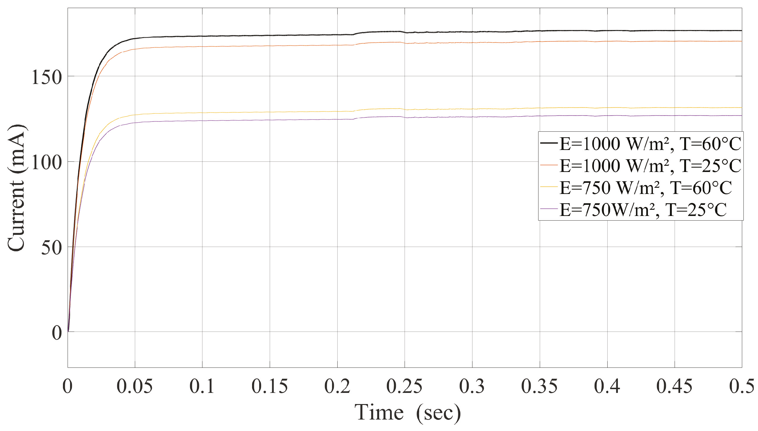
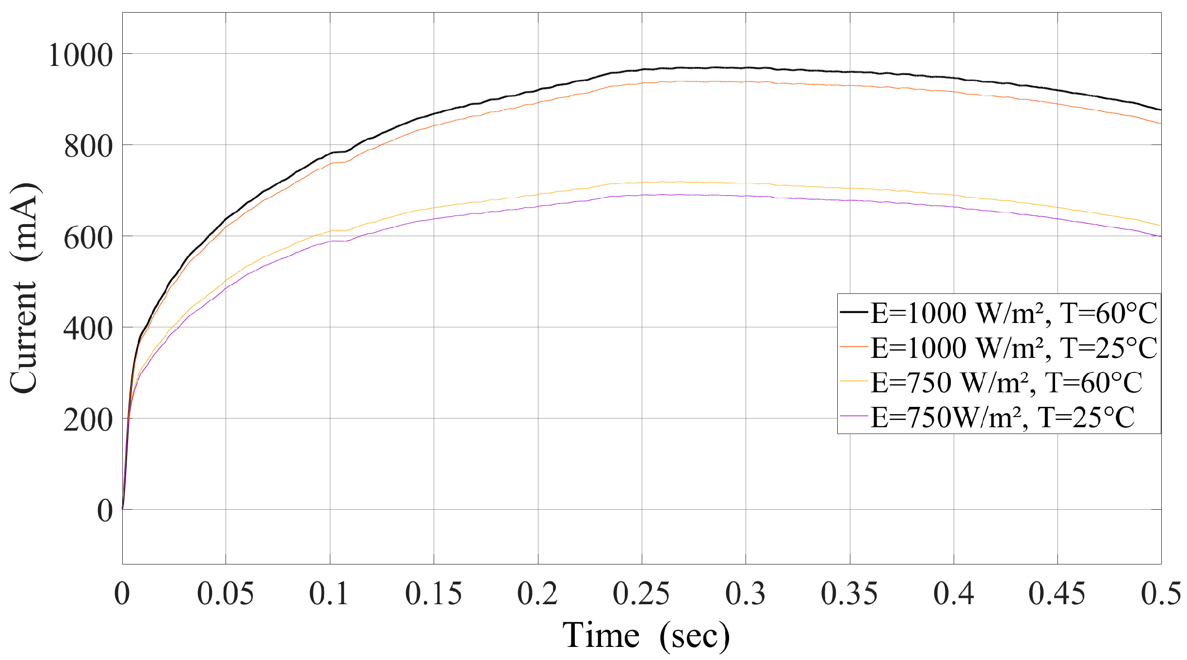
  • Performance Under Varying Irradiance and Temperature: The fluctuating conditions of irradiance and temperature significantly influence the operational efficiency of PV systems, necessitating a comparison of the ability of FLC and MPC to sustain MPPT efficiency amidst these variances.

6.2. Implications and Practical Limitations

The study primarily relies on simulations with a standard photovoltaic system model, which may not fully capture the effects of real-world conditions like partial shading or long-term panel degradation. Additionally, while the analysis includes P&O as a baseline, other widely used methods such as Incremental Conductance were not fully explored. The computational complexity of MPC was noted, but its impact on real-time implementation was not thoroughly analyzed.
The results show that MPC outperforms FLC in minimizing steady-state error and managing dynamic changes. However, MPC’s high computational demand poses a challenge for real-time applications. FLC, while easier to implement and less computationally intensive, struggles to match MPC’s precision and robustness, particularly under varying conditions. The combination of MPC and PI control, as presented in Figure 12, provides a promising approach to balancing performance and computational efficiency.
In the context of battery safety current management, these findings have significant implications. The robust precision of MPC makes it particularly effective in mitigating the risks associated with overcurrent and overcharging as it can dynamically adjust the control parameters to ensure safe operating conditions even during rapid load changes. This dynamic capability is critical for preventing thermal runaway and extending battery lifespan. However, the computational intensity of MPC may limit its application in cost-sensitive or resource-constrained environments.
FLC, on the other hand, offers a more accessible solution for safety current management in simpler systems. Its ease of implementation and lower computational requirements make it suitable for applications where high precision is less critical. Nevertheless, its limited ability to handle complex, rapidly changing scenarios may introduce safety vulnerabilities, particularly in systems with high variability or aggressive charging requirements. Combining MPC with traditional strategies like PI not only addresses the computational constraints but also enhances safety. The hybrid approach can provide a balance between precision and practicality, ensuring effective current management while maintaining computational efficiency. This synergy could play a pivotal role in advancing battery management systems for next-generation energy storage technologies.
MPC requires real-time optimization, which demands significant processing power and memory. This can limit its use in low-cost or resource-constrained environments unless optimization techniques such as reduced-order modeling are applied. In contrast, FLC has moderate computational requirements, making it suitable for mid-level hardware platforms. P&O, with its minimal computational complexity, is ideal for low-cost systems but sacrifices precision and stability for simplicity.
To enhance their practical relevance, future research could provide benchmarks for these methods, analyzing factors like execution time, memory usage, and processor load. Additionally, hybrid strategies that optimize both computational efficiency and control performance could improve the real-world applicability of these techniques.
The superior performance of the proposed methods can be attributed to key factors, including the following:
  • Predictive control optimization: The MPC algorithm anticipates future changes, enabling smooth and fast adjustments to maintain optimal power tracking.
  • Nonlinear system handling: The FLC approach effectively manages system uncertainties, ensuring stable performance even in resource-constrained environments.
  • Hybrid control integration: The combination of MPPT strategies with a PI-controlled buck converter enhances system stability and mitigates the risks of overcurrent and voltage fluctuations.
These factors highlight the practical relevance and scalability of the proposed methods for real-world PV systems.

6.3. Future Direction

Future research could focus on experimental validation to support the simulation results and enhance practical applicability. Improvements to the PV system model, incorporating environmental factors, would also be beneficial. Moreover, optimization of MPC for resource-constrained systems and expanded comparisons with additional MPPT techniques could further strengthen the study’s findings.
In addition, further improvements to the PV system model are warranted. Incorporating a broader range of environmental factors—such as fluctuations in temperature, variations in solar irradiance, humidity levels, and even the impact of dust or shading—could significantly enhance the model’s accuracy. By accounting for these dynamic variables, researchers can develop a more robust system that mirrors the complexities of real-life operation, thereby improving prediction reliability and system performance.

7. Conclusions

This study presents a comprehensive comparative evaluation of MPC versus FLC for MPPT in PV systems, focusing on their respective advantages and drawbacks under varying applications and environmental conditions. In terms of steady-state performance, while FLC is more computationally efficient (requiring about 30% less computational time compared to MPC), it struggles with significant steady-state oscillations, especially under rapidly changing irradiance conditions. These oscillations can cause deviations from the MPP of about 2-3%. On the other hand, MPC better suppresses these oscillations, maintaining more accurate MPP tracking with steady-state errors typically within 1%. From a computational efficiency standpoint, FLC’s low computational demand enables it to perform well in embedded systems with limited computational resources. Especially in low-power devices, FLC can effectively implement MPPT without the need for complex computations. In comparison, MPC, while offering better performance, requires a more powerful computational platform and is therefore more suitable for complex systems and environments with adequate computational resources. Overall, MPC and FLC each have advantages depending on the application scenario. MPC is optimal for systems requiring a rapid response and capable of handling significant environmental variations, provided there are sufficient computational resources. It offers higher efficiency and more precise power tracking. On the other hand, FLC is well suited for scenarios with limited computational resources, particularly in stable environmental conditions where real-time calculations are less critical, providing an efficient and cost-effective solution.

Author Contributions

Conceptualization, Z.L.; methodology, Z.L. and G.D.; software, Z.L. and G.D.; validation, Z.L. and G.D.; formal analysis, Z.L.; investigation, Z.L. and G.D.; resources, Z.L. and G.D.; data curation, Z.L. and G.D.; writing—original draft preparation, Z.L.; writing—review and editing, T.X. and A.S.; visualization, Z.L. and G.D.; supervision, G.D.; project administration, Z.L. and G.D. All authors have read and agreed to the published version of the manuscript.

Funding

This research received no external funding.

Data Availability Statement

Data are contained within the article.

Conflicts of Interest

The authors declare no conflicts of interest.

References

  1. Hassan, M.A.; Adel, M.M.; Saleh, A.A.; Eteiba, M.B.; Farhan, A. Maximum Power Point Tracking based on finite voltage-set MPC for grid-connected photovoltaic systems under environmental variations. Sustainability 2024, 16, 10317. [Google Scholar] [CrossRef]
  2. Xie, J.; Xu, L.; Zhang, H.; He, Y.; Ghandour, R.M.R.; Zhou, J.; Ge, Y.; Li, Q. Characteristic harmonic spectrum relocating for controlling specific inter-harmonics of inverters with new phase-shifted rotating PWM. IEEE Access 2020, 8, 191005–191027. [Google Scholar] [CrossRef]
  3. Solanics, P.; Kozminski, K.; Bajpai, M.; Esztergalyos, J.; Fennell, E.; Gardell, J.; Mozina, C.; Patel, S.; Pierce, A.; Skendzic, V.; et al. The impact of large steel mill loads on power generating units. IEEE Trans. Power Deliv. 2000, 15, 24–30. [Google Scholar] [CrossRef]
  4. Nadeem, A.; Hussain, A. A comprehensive review of global maximum power point tracking algorithms for photovoltaic systems. Energy Syst. 2021, 14, 293–334. Available online: https://link.springer.com/article/10.1007/s12667-021-00476-2 (accessed on 6 January 2025). [CrossRef]
  5. Wang, F.; Bollen, M. Measurement of 182 Hz Interharmonics and Their Impact on Relay Operation. In Proceedings of the International Conference on Harmonics and Quality of Power, Orlando, FL, USA, 1–4 October 2000; pp. 55–60. [Google Scholar]
  6. Koponen, P.; Hansen, H.; Bollen, M. Interharmonics and Light Flicker. In Proceedings of the 23rd International Conference on Electricity Distribution (CIRED 2015), Lyon, France, 15–18 June 2015; p. 1100. [Google Scholar]
  7. Langella, R.; Testa, A.; Djokic, S.Z.; Meyer, J.; Klatt, M. On the Interharmonic Emission of PV Inverters under Different Operating Conditions. In Proceedings of the International Conference on Harmonics and Quality of Power (ICHQP), Belo Horizonte, Brazil, 16–19 October 2016; pp. 1–6. [Google Scholar]
  8. Zhang, T.; Stackhouse, P.W.; Macpherson, B.; Mikovitz, J.C. Short-term photovoltaic power prediction strategies based on meteorological reconstruction. Sol. Energy 2024, 238, 1–12. [Google Scholar]
  9. Liao, Y.; Chen, W. Design and implementation of an MPPT-based energy management system for microgrids. IEEE Trans. Smart Grid 2019, 10, 4914–4923. [Google Scholar]
  10. Singh, J.; Verma, A.K.; Sharma, S.K. Advanced Control Strategies for Optimal Power Transfer in Grid-Connected PV Systems: A Review. Energy Rep. 2021, 7, 429–450. [Google Scholar]
  11. Zhang, T.; Stackhouse, P.W.; Macpherson, B.; Mikovitz, J.C. A novel multiple-medium-AC-port power electronic transformer. IEEE Trans. Power Deliv. 2024, 39, 100–115. [Google Scholar] [CrossRef]
  12. Wang, P.; Li, Z.; Xu, D. An asymmetric hybrid phase-leg modular multilevel converter with small volume, low cost, and DC fault-blocking capability. IEEE Trans. Power Electron. 2024, 39, 1000–1012. [Google Scholar]
  13. Langella, R.; Testa, A.; Meyer, J.; Möller, F.; Stiegler, R.; Djokic, S.Z. Experimental-based evaluation of PV inverter harmonic and interharmonic distortion due to different operating conditions. IEEE Trans. Instrum. Meas. 2016, 65, 2221–2233. [Google Scholar] [CrossRef]
  14. Sangwongwanich, A.; Yang, Y.; Sera, D.; Soltani, H.; Blaabjerg, F. Analysis and modeling of interharmonics from grid-connected photovoltaic systems. IEEE Trans. Power Electron. 2018, 33, 8353–8364. [Google Scholar] [CrossRef]
  15. Sangwongwanich, A.; Blaabjerg, F. Interharmonics Reduction in Photovoltaic Systems with Random Sampling MPPT Technique. In Proceedings of the IEEE Energy Conversion Congress and Exposition (ECCE), Baltimore, MD, USA, 29 September–3 October 2019; pp. 4760–4765. [Google Scholar]
  16. Luo, Q.; Zhong, Q.; Wang, G. An order-reduction method of interharmonic analysis model based on the principle of interharmonic interaction. CPSS Trans. Power Electron. Appl. 2021, 6, 209–217. [Google Scholar] [CrossRef]
  17. Alfaris, F.E.; Al-Ammar, E.A.; Ghazi, G.A.; Al-Katheri, A.A. Design enhancement of grid-connected residential PV systems to meet the Saudi electricity regulations. Sustainability 2024, 16, 5235. [Google Scholar] [CrossRef]
  18. Zhang, X.; Li, Y.; Zhou, W.; Zhou, Q. Enhanced Maximum Power Point Tracking for PV systems using a predictive control approach. IEEE Access 2020, 8, 50315–50324. [Google Scholar]
  19. Ali, M.; Ahmad, A.; Khan, R.; Iqbal, M. A comprehensive review of MPPT techniques for standalone and grid-connected PV systems. Renew. Energy 2023, 205, 175–188. [Google Scholar]
  20. Yılmaz, U.; Kircay, A.; Börekci, S. PV System Fuzzy Logic MPPT Method and PI Control as a Charge Controller. Renew. Sustain. Energy Rev. 2018, 81, 994–1001. [Google Scholar] [CrossRef]
  21. Tofigh Rihani, A.; Ghandchi, M. Increasing the Efficiency of Photovoltaic Systems by Using Maximum Power Point Tracking (MPPT). arXiv 2021, arXiv:2201.00403. [Google Scholar]
  22. Paduani, V.; Yu, H.; Xu, B.; Lu, N. A Unified Power-Setpoint Tracking Algorithm for Utility-Scale PV Systems with Power Reserves and Fast Frequency Response Capabilities. arXiv 2021, arXiv:2105.05324. [Google Scholar] [CrossRef]
  23. Kim, E.; Warner, M.; Bhattacharya, I. Adaptive Step Size Incremental Conductance Based Maximum Power Point Tracking (MPPT). arXiv 2020, arXiv:2011.07649. [Google Scholar]
  24. Za’ter, M.E.; Miguel, S.Y.; Batarseh, M.G. Online Gradient Descent for Flexible Power Point Tracking Under a Highly Fluctuating Weather and Load. arXiv 2022, arXiv:2203.00197. [Google Scholar]
  25. Lin, C.-H.; Farooqui, S.A.; Liu, H.-D.; Huang, J.-J.; Fahad, M. Finite Control Set Model Predictive Control (FCS-MPC) for enhancing the performance of a single-phase inverter in a Renewable Energy System (RES). Mathematics 2023, 11, 4553. [Google Scholar] [CrossRef]
  26. Preeti, G.A.; Karthikeyan, A. Finite control set Model Predictive Control of three-port converter for interfacing a PV–battery energy storage system to a three-phase stand-alone AC system. Clean Energy 2024, 8, 73–84. [Google Scholar] [CrossRef]
  27. Le, V.-T.; Lee, H.-H. Robust finite-control-set Model Predictive Control for voltage source inverters against LC-filter parameter mismatch and variation. J. Power Electron. 2022, 22, 406–419. [Google Scholar] [CrossRef]
  28. Rao, R.; Kumar, A.; Bansal, R.C. Dynamic Analysis of PV Systems Using Adaptive MPPT for Maximum Power Transfer. IEEE Trans. Energy Convers. 2022, 37, 350–359. [Google Scholar]
  29. Baumgartner, F.; Janßen, C.; Bonhage, A.; Hillebrecht, G. Effect of Temperature and Irradiance on the Performance of PV Modules. In Proceedings of the IEEE Photovoltaic Specialists Conference (PVSC 2020), Calgary, AB, Canada, 15–19 June 2020; pp. 2450–2454. [Google Scholar]
Figure 1. Power-electronic-based PV system.
Electronics 14 01009 g001
Figure 2. Buck converter schematic.
Electronics 14 01009 g002
Figure 3. Fuzzy sets’ membership functions: (a) change in error (CE); (b) error (E); (c) duty (D).
Electronics 14 01009 g003
Figure 4. FLC controller structure.
Electronics 14 01009 g004
Figure 5. Duty calculated by FLC.
Electronics 14 01009 g005
Figure 6. Duty calculated by MPC.
Electronics 14 01009 g006
Figure 7. Current response using FLC and PI control under dynamic conditions.
Electronics 14 01009 g007
Figure 8. Current response using MPC and PI control under dynamic conditions.
Electronics 14 01009 g008
Figure 9. Voltage response using FLC and PI control.
Electronics 14 01009 g009
Figure 10. Voltage response using MPC and PI control.
Electronics 14 01009 g010
Figure 11. Current at different temperatures and irradiance levels under FLC.
Electronics 14 01009 g011
Figure 12. Current at different temperatures and irradiance levels under MPC.
Electronics 14 01009 g012
Figure 13. Current at different temperatures and irradiance levels under P&O.
Electronics 14 01009 g013
Table 1. Electrical characteristics of PV panel.
ParameterValue
The open circuit voltage ( V oc )24 V
The short circuit current ( I sc )5.1 A
The voltage at MPP ( V mpp )17.5 V
The current at MPP ( I mpp )4.8 A
The power at MPP ( P mpp )84 W
Temperature coefficient of open circuit voltage (%/°C)−0.36099
Temperature coefficient of I sc (%/°C)0.102
Number of cells ( N cell )20
Table 2. Design parameters of buck converter.
ParameterValue/Range
Inductor (L)100 μH
Capacitor (C)470 μF
MOSFET Voltage Rating50 V
Diode Voltage Rating50 V
Table 3. The rule table for FLC.
E/CEPBPMPSZENSNMNB
PBZEZEZENBNBNBNB
PMZEZEZENMNMNMNM
PSZEZEZENSNSNMNM
ZENSNSZEZEPSPSPS
NSPMPMPSNSZEPSZE
NMPMPMPMPBZEZEZE
NBPBPMPMPBZEZEZE
Disclaimer/Publisher’s Note: The statements, opinions and data contained in all publications are solely those of the individual author(s) and contributor(s) and not of MDPI and/or the editor(s). MDPI and/or the editor(s) disclaim responsibility for any injury to people or property resulting from any ideas, methods, instructions or products referred to in the content.

