Article

A Miniaturized Eight-Port MIMO Antenna for 5G Ultra-Slim Smartphones

College of Electrical and Electronic Engineering, Wenzhou University, Wenzhou 325035, China
*
Author to whom correspondence should be addressed.
Electronics 2025, 14(3), 566; https://doi.org/10.3390/electronics14030566
Submission received: 2 January 2025 / Revised: 26 January 2025 / Accepted: 30 January 2025 / Published: 30 January 2025
(This article belongs to the Section Microwave and Wireless Communications)

Abstract

:
This paper presents the design of a miniaturized eight-port multiple-input multiple-output (MIMO) antenna. Each proposed antenna element occupies only 6.2 × 7 × 0.8 mm³, making it ideal for integration into ultra-slim 5G smartphones. The proposed MIMO antenna offers a −10 dB impedance bandwidth of 1.7 GHz (3.3 to 5.0 GHz), covering the N77 (3.3–4.2 GHz), N78 (3.3–3.8 GHz), and N79 (4.8–5.0 GHz) bands. The isolation between the antenna elements is larger than 16 dB. The envelope correlation coefficient (ECC) of the designed antenna is lower than 0.09. Meanwhile, the peak gain exceeds 2.2 dBi, the efficiency surpasses 70%, and the diversity gain (DG) is higher than 9.95. This innovative design addresses the demands of ultra-slim mobile devices while maintaining high performance.

1. Introduction

Recently, the evolution of 5G communication technologies has brought about a significant transformation in wireless communications. The World Radio Communication Conference 2015 (WRC-15) allocated critical frequency bands spanning 3.3–3.4 GHz, 3.6–3.7 GHz, and 4.8–5 GHz. Subsequently, China approved the frequency bands of 3.3–3.6 GHz and 4.8–5 GHz for 5G communication [1]. Although there is growing anticipation for 6G communications, 5G continues to be a cornerstone in the field of wireless communication. It is confronted with various challenges associated with both sub-6 GHz and millimeter-wave bands [2]. For instance, in the sub-6 GHz band, issues like limited bandwidth and interference need to be addressed. To tackle these challenges and improve the performance of 5G networks, multi-input multi-output (MIMO) antenna technology has emerged as a key solution [3]. The utilization of multiple spatial dimensions within MIMO antennas allows for enhanced signaling and spectral efficiency, making them essential for the high-speed, low-latency demands of 5G communication [4,5].
The design of MIMO antennas in confined spaces, especially within the constraints of mobile devices, is a topic of intense discussion. Achieving high performance in such environments is a critical challenge for 5G antenna technology. To accommodate the 5G frequency bands without enlarging the device, antennas are often integrated on metal frames [6]. Research on 5G MIMO antennas primarily focuses on the 3.3 GHz to 5 GHz frequency range [7,8,9]. In [10], an MIMO antenna with a co-coupled fed IFA (inverted-F antenna) loop structure was proposed, covering the frequency bands of 3.3 GHz to 6.4 GHz. An MIMO antenna comprising an inverted L-shaped feed branch was presented in [11], operating within 3.3–3.6 GHz and 4.8–5 GHz. Furthermore, reference [12] proposed an MIMO antenna system composed of a dual-arm tortuous monopole radiating element spanning the 3.2 to 6 GHz bands. An element slotted octagon-shaped antenna was proposed in [13], which enabled the antenna to operate in the sub-6 GHz band (3.1–4.5 GHz).
To address the design challenges associated with maintaining adequate isolation in 5G MIMO antennas, various decoupling methods have been proposed [10,14,15,16]. These methods aim to enhance isolation and reduce mutual interference within the limited space of mobile terminals, particularly in the sub-6 GHz bands. Among these, the ground decoupling method has been widely applied to 5G MIMO antenna systems. Specifically, the use of Defected Ground Structure (DGS) has been shown to be effective in modifying the ground plane of the antenna to create specific defects that disrupt surface currents, thereby reducing coupling between adjacent antennas [17]. A variant of DGS, inserted L-shaped and rectangle slots in the ground plane, has been presented to contribute significantly to the reduction in coupling [18]. The offset-fed configuration is another approach that achieves high isolation between antenna elements by concentrating the surface current and near fields of each element on their respective sides, eliminating the need for additional isolation techniques [19]. This design is particularly effective for adjacent antennas with irregular structures that are completely symmetrical, enhancing isolation without the need for additional isolation designs [20]. However, the effectiveness of this approach is mainly dependent on the geometric shape of the antenna itself, with limited effectiveness for antenna designs with relatively uniform current distributions. Self-isolated elements, designed to minimize mutual coupling through specific network configurations, have also been proposed for decoupling [21]. Additionally, the use of extra parasitic patches as a decoupling method has been employed to enhance isolation [22]. These parasitic elements act as supplementary radiating sources, generating extra resonances that influence the current distribution and, consequently, the isolation between antennas. The introduction of parasitic elements has been shown to result in higher isolation between the excited antenna and those not excited [23]. Electromagnetic Bandgap (EBG) structures have emerged as a research hotspot for decoupling in 5G MIMO antennas. The cascading EBG structures have been introduced to minimize mutual coupling among antenna elements and enhance the performance of MIMO antennas [24]. A fractal H-shaped metamaterial EBG isolator has been presented, which increases isolation by over 10 dB [25]. Pattern diversity techniques have also been employed to reduce mutual coupling. These techniques enable the antenna to function with orthogonal modes, namely, in-phase and out-of-phase modes, which effectively minimize the strong coupling between antenna elements [26]. The excitation of one port induces an in-phase mode, whereas the other port’s excitation produces an out-of-phase mode, thereby achieving high isolation when the ports are activated individually and resulting in in-phase and out-of-phase current distributions on the two monopoles [27]. In summary, the various decoupling techniques for 5G MIMO antennas, including ground decoupling methods, offset-fed configurations, self-isolated elements, parasitic elements, EBG structures, and pattern diversity techniques, play a crucial role in enhancing isolation and reducing mutual interference, addressing the design challenges posed by the need for multiple antenna elements in limited spaces.
This paper presents a compact eight-element MIMO antenna designed for 5G smartphones. The antenna element’s −10 dB impedance bandwidth encompasses the N77 (3.3–4.2 GHz), N78 (3.3–3.8 GHz), and N79 (4.8–5.0 GHz) bands. Several decoupling structures have been proposed to ensure high isolation between the antenna elements. Ansys Electronics Desktop 2024 R1 is used as the electromagnetic simulator. The performance of the proposed eight-element MIMO antenna is validated through both simulation and measurement.

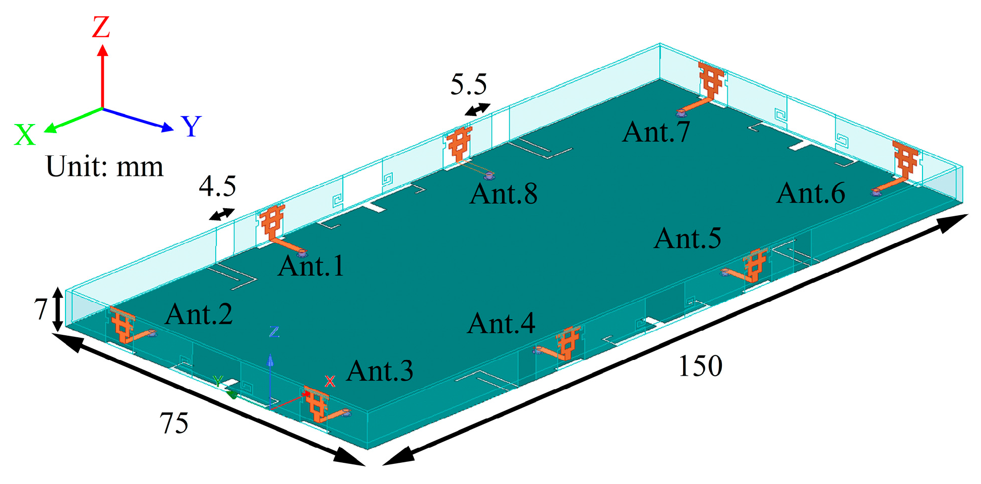
2. Antenna Geometry and Design

The geometry of the proposed eight-element MIMO antenna is depicted in Figure 1. The proposed MIMO antenna is printed on a main board, two long sideboards, and two short sideboards. The main board has a dimension of 150 mm × 75 mm × 0.8 mm. The short sideboard and the long sideboard measure 75 mm × 0.8 mm × 7 mm and 150 mm × 7 mm × 0.8 mm, respectively. The proposed eight-element MIMO antenna has an overall size of 150 mm × 75 mm × 7 mm. The radiators of eight antenna elements are printed on the sideboards, which are positioned perpendicularly to the main board and are fed by a microstrip line measuring 8 mm × 1.5 mm. The four side boards are bonded to the main board as well as to each other using metallic adhesive. Both the sideboards and the main board are made from an FR4 substrate with a dielectric constant (εr) of 4.4 and a loss tangent (tanδ) of 0.02.

2.1. Antenna Element Design

Figure 2a shows the radiator of type 1 antenna elements (including Ant. 2, Ant. 3, Ant. 6, and Ant. 7) which are printed on the short sideboards. Figure 2b shows the radiator of type 2 antenna elements (including Ant.1, Ant.4, Ant.5, and Ant.8) which are printed on the long sideboards. Figure 2c illustrates the defected ground plane of both type 1 and type 2 antenna elements. The overall size of two types of antenna elements measures 6.8 mm × 7 mm × 0.8 mm. Table 1 shows the optimized geometric parameters of the proposed antenna elements.

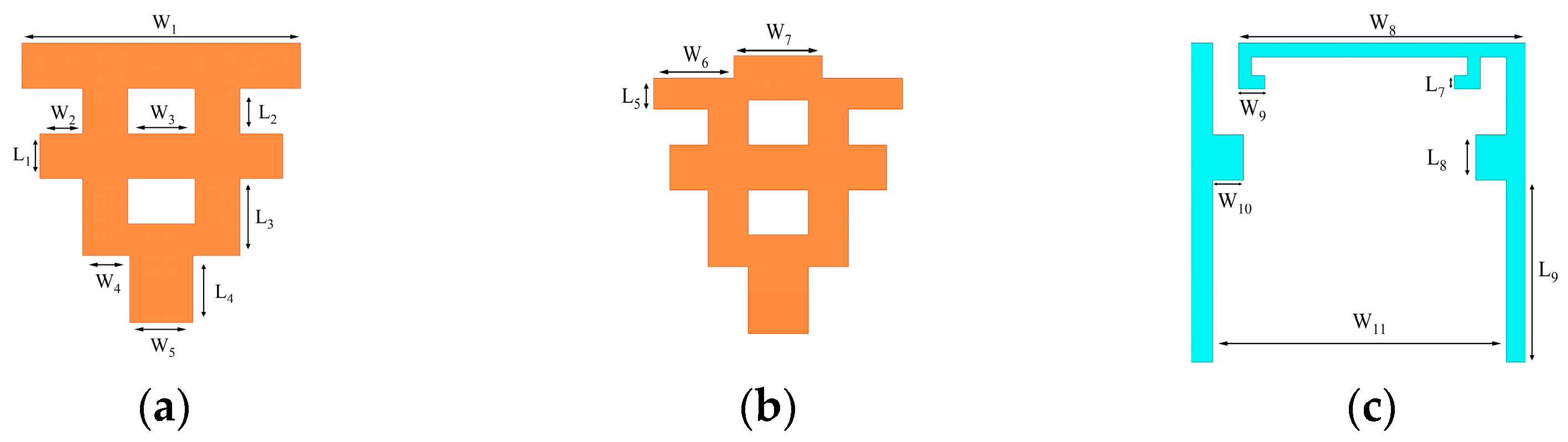
2.2. Evolution of the Radiator of Antenna Elements

To enhance the understanding of the design evolution for antenna elements, four kinds of radiators have been developed (Stage 1 to Stage 4), as depicted in Figure 3a. Stage 3 is the radiator of the proposed type 1 antenna element, while stage 4 is the radiator of the proposed type 2 antenna element. The simulated reflection coefficients for each stage are shown in Figure 3b.

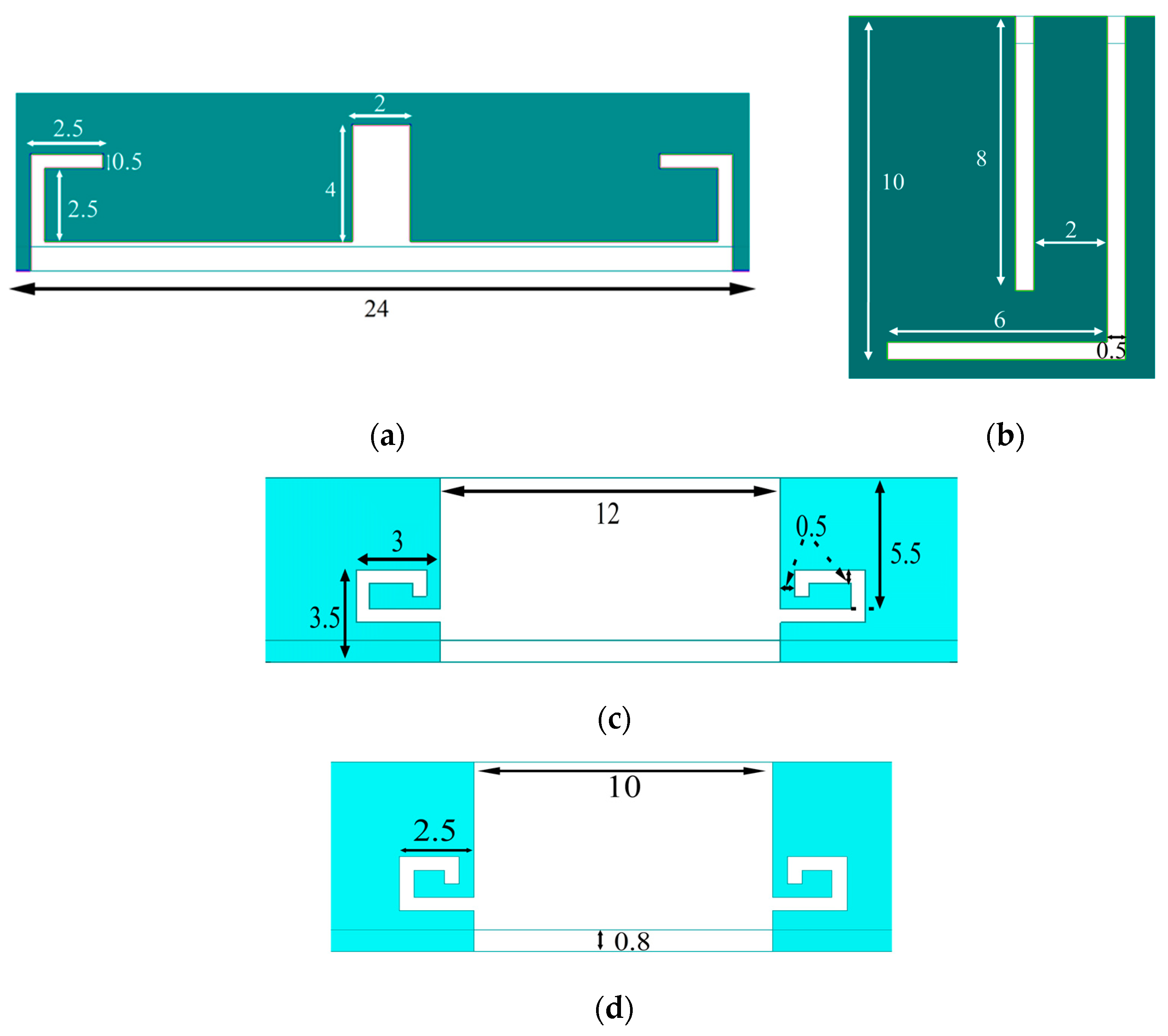
2.3. Decoupling Structure
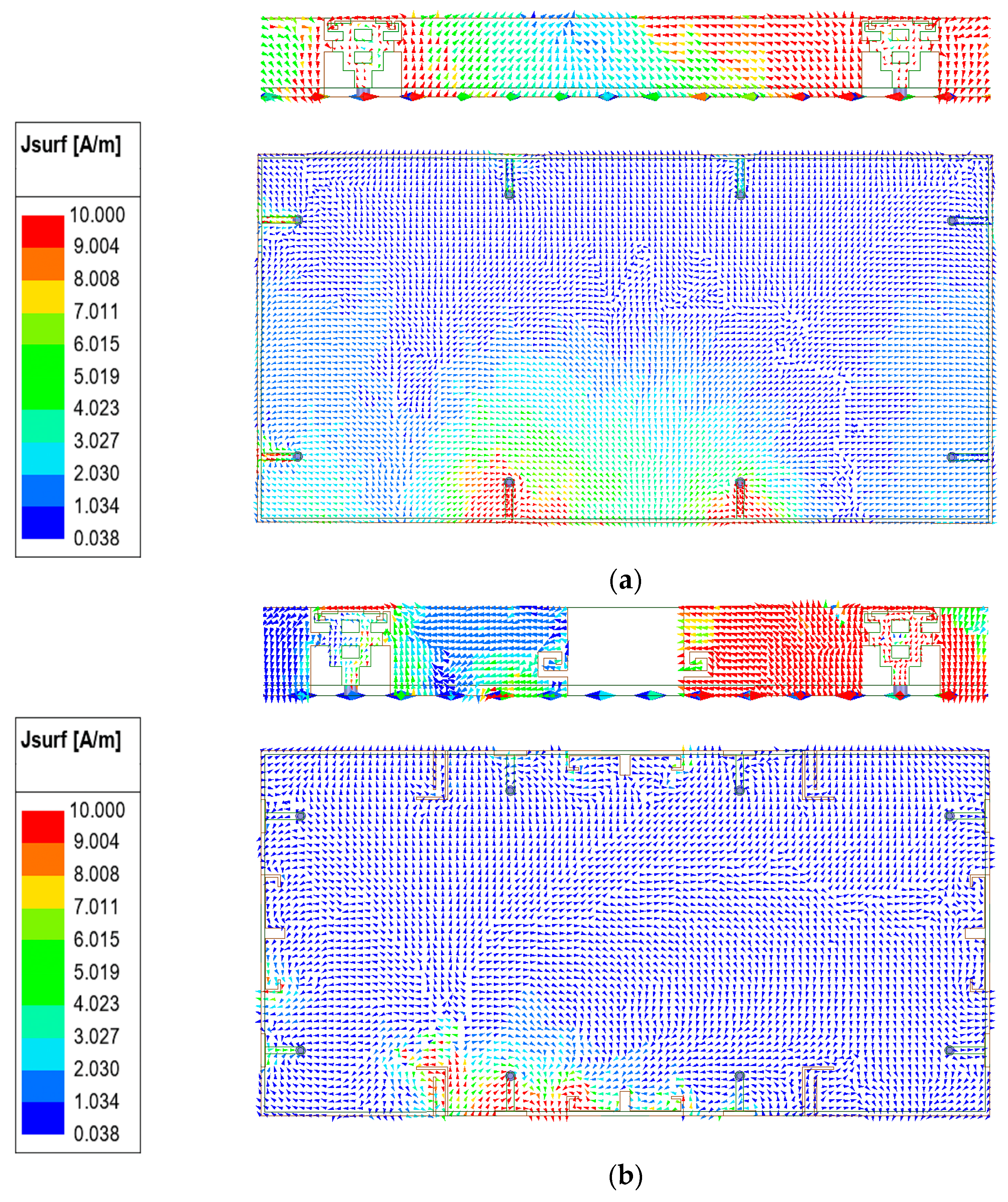
Numerous decoupling techniques have been explored to enhance the isolation between adjacent antenna elements. As shown in Figure 4, the proposed decoupling structures (DS) DS1 and DS2 are decoupling slots etched on the mainboard’s top surface, while DS3 and DS4 are etched on the outer surfaces of the short and long sideboards, respectively. DS1 is introduced to improve the isolation between adjacent type 1 and type 2 antenna elements. DS2 is employed to mitigate coupling between adjacent type 1 antenna elements and also between adjacent type 2 antenna elements. DS3 is used to reduce coupling both between Ant. 1 and Ant. 8, as well as between Ant. 4 and Ant. 5. DS4 is applied to mitigate coupling between Ant. 2 and Ant. 3, as well as between Ant. 6 and Ant. 7.
To validate the operational principle of the decoupling structures, the surface current distributions with and without the decoupling structures are compared, as shown in Figure 5 and Figure 6. This indicates that these structures play a certain role in influencing the current distribution in contrast to the absence of them. As can be seen from Figure 5, when Ant. 1 is excited at 3.5 GHz, the current density on the outer surfaces of the sideboard is concentrated on the right side of DS3 (the side closer to Ant.1), which significantly reduces the coupling between Ant. 1 and Ant. 8. On the ground plane, the current density is distributed over the inner edges of the slots of DS1 and DS2. This decreases the coupling between Ant. 1 and Ant. 2 and further enhances the decoupling of Ant. 1 and Ant. 8. When Ant. 1 is excited at 4.8 GHz, as shown in Figure 6, the effect of DS3 weakens, and DS1 and DS2 play a crucial role in providing decoupling in this frequency band.
As shown in Figure 7a, the simulated transmission coefficients without decoupling structures do not meet the requirements in the desired frequency bands, especially the transmission coefficients of S13, S23, and S45. Figure 7b reveals that the introduction of the decoupling slots significantly enhances the isolation. Compared with the results in Figure 7, the isolation significantly improves across multiple ports: S13 increases from 5 dB to 30 dB, S23 from 13 dB to 30 dB, and S45 from 5 dB to 15 dB.

3. Antenna Analysis

This section focuses on two main aspects, including the impact of the lengths of rectangular microstrips and the influence of a hand phantom on the antenna’s performance. In the Single Hand Mode (SHM), the reflection coefficients and transmission coefficients are presented. Moreover, the electric field distribution and 3D radiation patterns are introduced in the SHM.

3.1. Parameter Analysis

The impact of the lengths of the rectangular microstrips, denoted as W3 and W1, on the reflection coefficients has been analyzed to achieve optimal performance. Figure 8a presents the reflection coefficients as a function of W1. It is observed that an increase in the W1 value results in negligible effects on the lower frequency band, while it induces a shift in the higher frequency band. This observation is pivotal for fine-tuning the antenna’s impedance matching within the targeted frequency bands. Figure 8b depicts the influence of W3 on the reflection coefficients, demonstrating that a reduction in W3 leads to minimal alterations in the higher frequency range, while the lower frequency range experiences an upward shift towards higher frequencies. Specifically, setting W3 to 1.5 mm ensures that the −10 dB impedance bandwidths for both the higher and lower frequency bands align with the specified requirements. This optimization is crucial for ensuring the antenna’s operational efficiency across the desired frequency bands.

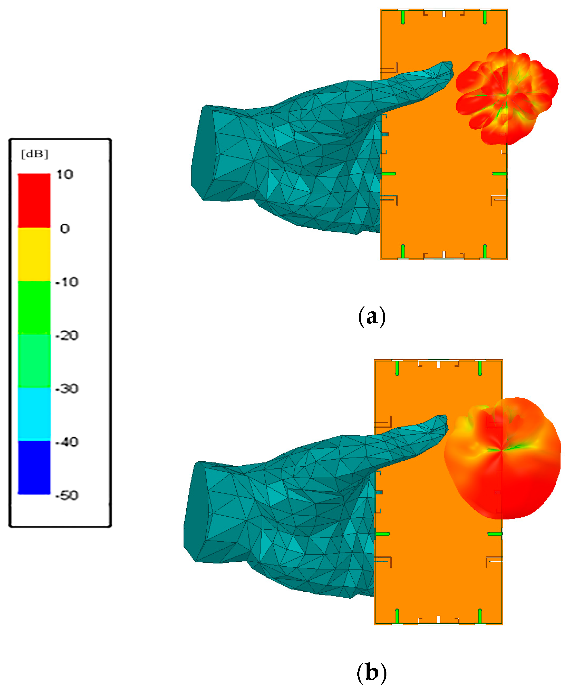
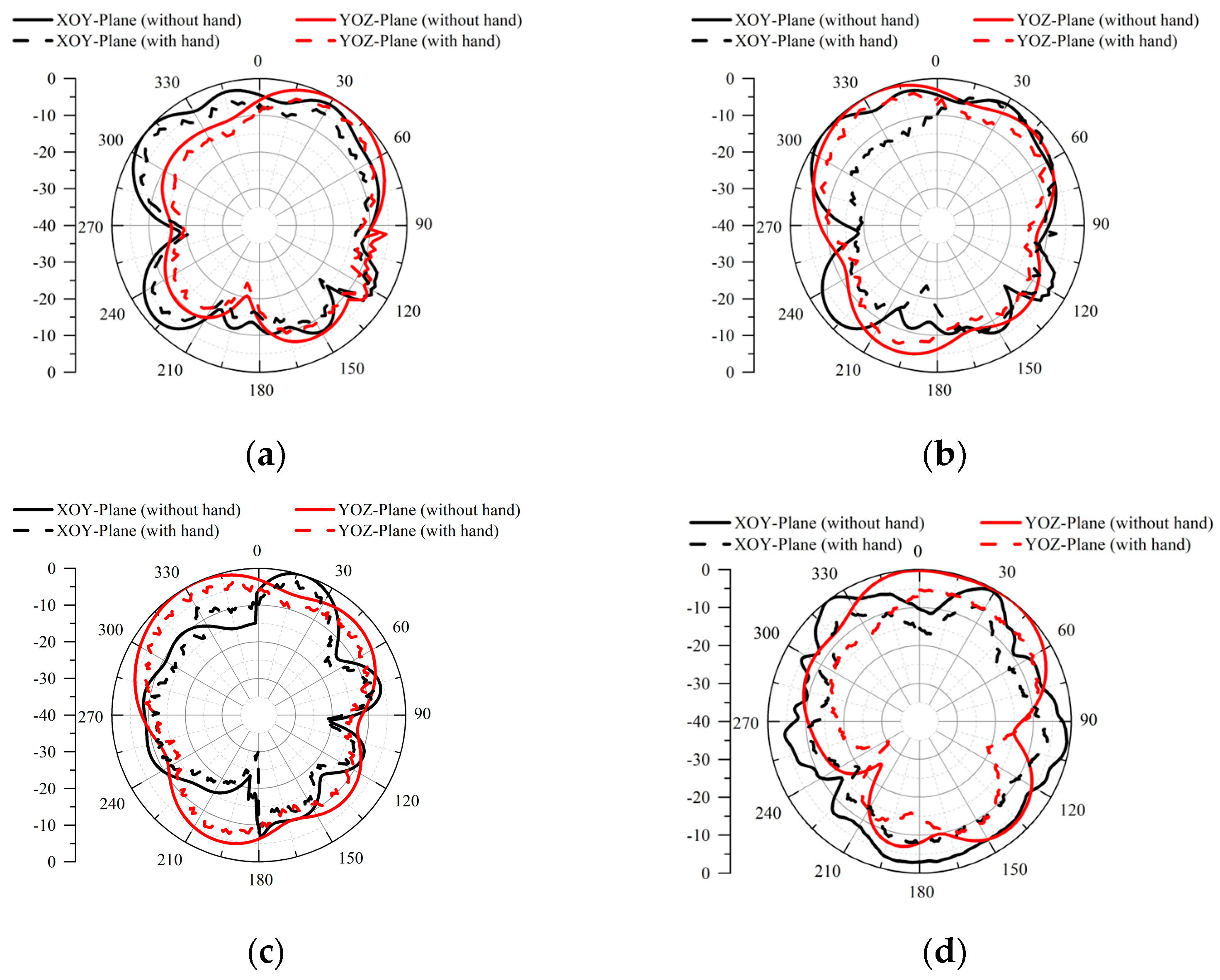
3.2. Assessment of Simulated Operational Scenarios

In this section, the influence of a hand phantom on the antenna’s performance is investigated. Figure 9 illustrates a typical application scenario, specifically the Single Hand Mode (SHM), and presents the corresponding simulated S-parameters and radiation patterns. The reflection coefficients of these antenna elements exhibit a significant degradation across two frequency bands, as illustrated in Figure 10a. Notably, the transmission coefficients exhibit minor fluctuations in the SHM, as observed in Figure 10b.
The three-dimensional (3D) radiation patterns and electric field distributions under the SHM are depicted in Figure 11 and Figure 12, respectively. Under SHM, the influence of the human hand on the antenna’s radiation such as absorption or reflection may affect the reflection and transmission coefficients. However, it is also important to note that this effect is considered a typical scenario in smartphone communication. In the design of smartphone antennas, understanding the electric field distribution is crucial for evaluating the antenna’s radiation properties and operational efficiency. An optimal distribution of the electric field can mitigate the radiation impact on the human body while also enhancing signal transmission and reception. An ideal antenna design aims to achieve a uniform electric field distribution, concentrated in the desired direction, thereby improving communication quality and minimizing energy dissipation. By employing meticulous simulation and testing, engineers can optimize the structure and positioning of the antenna, refining the electric field distribution patterns to accommodate diverse usage scenarios and performance specifications. While complete mitigation may not be feasible, the goal is to minimize the impact and maintain reliable communication.
In Figure 13, the radiation patterns of antenna type 1 and type 2 at 3.5 GHz and 4.8 GHz are observed to assess the influence of the hand. Under the SHM, there is degradation in the radiation patterns of the antenna elements. Specifically, for both the type 1 and type 2 antenna elements, the radiation patterns deviate from their ideal patterns with the hand’s presence. This degradation may be attributed to the hand acting as a scattering and absorbing medium. It disrupts the normal propagation of electromagnetic waves emitted by the antenna elements, thus affecting the radiation performance and resulting in the observed changes in the radiation patterns.

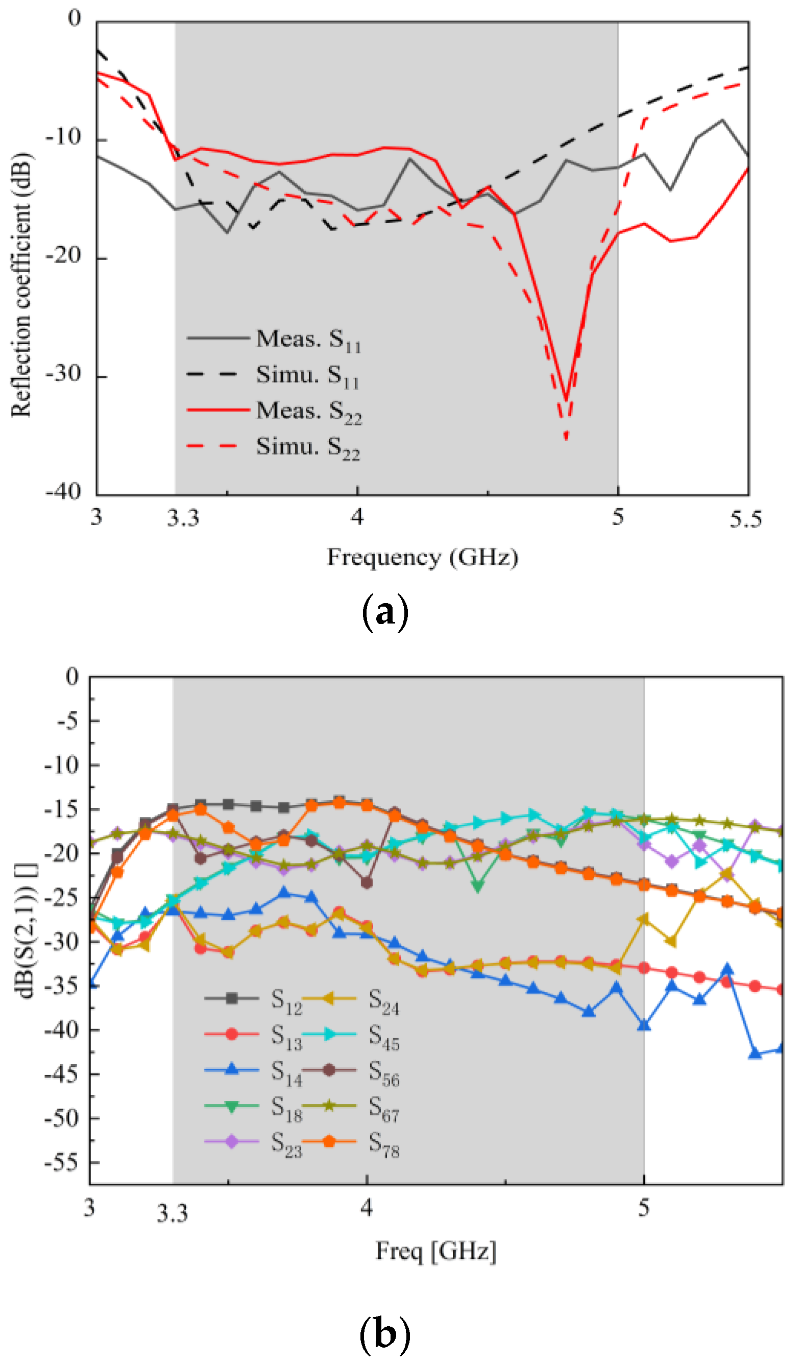
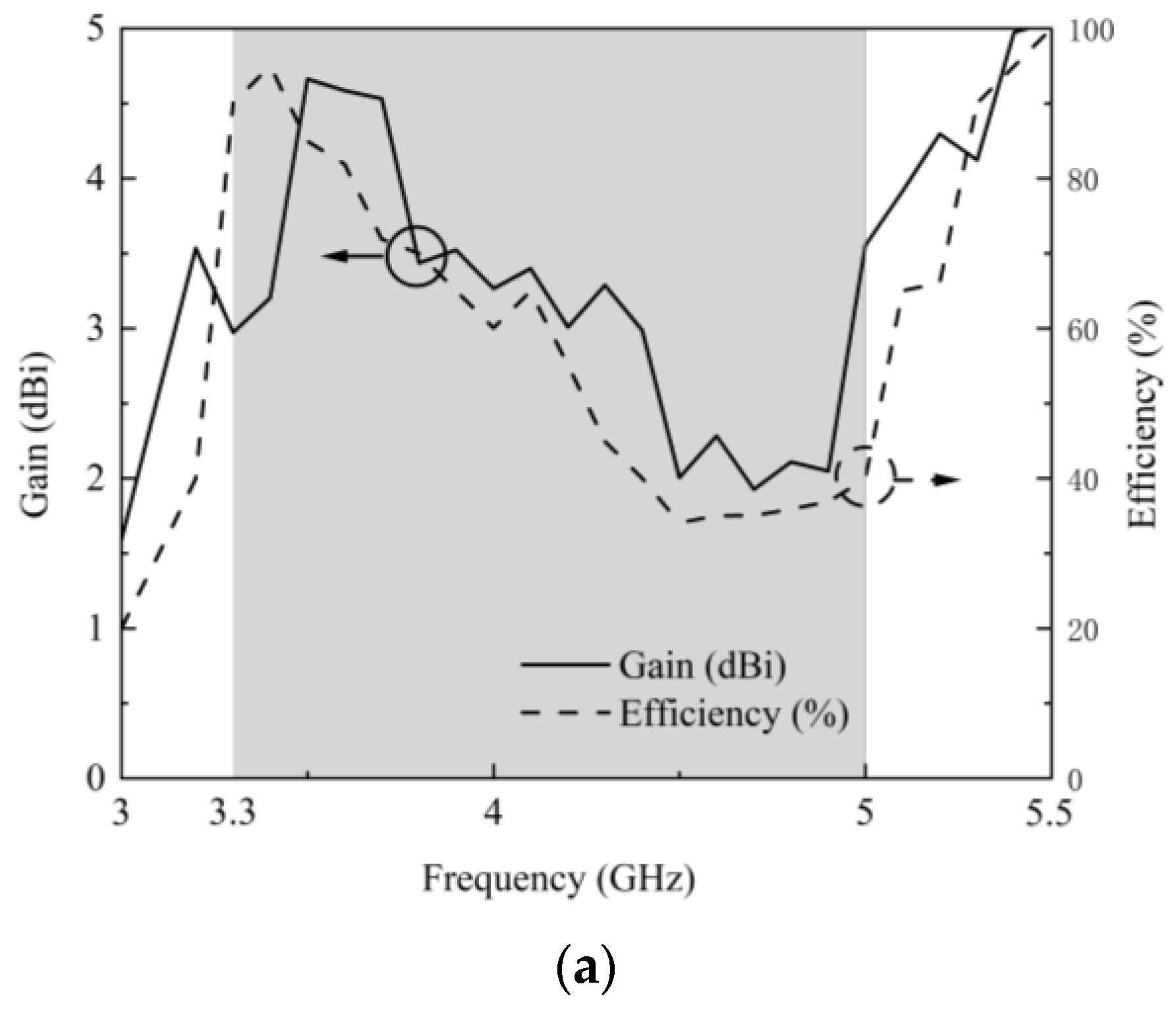
4. Experiment Results and Discussions

Figure 14 shows the photographs of the fabricated antenna prototype along with the testing equipment, including a Keysight Vector Network Analyzer (VNA) N5224A (Keysight Technologies, Santa Rosa, CA, USA) and an anechoic chamber.
Figure 15 shows the simulated and measured reflection coefficients and transmission coefficients. The measured −10 dB impedance bandwidth is 1.7 GHz, ranging from 3.3 to 5 GHz. The minimum observed isolation is between Ant. 1 and Ant. 2, at 16 dB. Figure 16 displays the acquired gain and radiating efficiency for Ant. 1 and Ant. 2. Within the operational bands N77 and N78, the proposed MIMO antenna achieves a peak gain and radiation efficiency of 4.66 dBi and 94.99%, respectively. In the N79 band, the peak gain and radiation efficiency are 5.24 dBi and 86.20%, respectively. The differences between the simulated and measured results are mainly due to manufacturing tolerances and measurement error.
Figure 17 presents the simulated and measured normalized 2D radiation patterns of the type 1 antenna element at 3.5 GHz and 4.8 GHz, while Figure 18 represents those of the type 2 antenna element. The radiation patterns of type 1 and type 2 antenna elements are nearly quasi-omnidirectional in the xoy plane and omnidirectional in the yoz plane. The disparities between the simulated and measured outcomes can be primarily attributed to antenna manufacturing tolerances, the influence of the measurement environment, and the inherent limitations in the accuracy of measurement equipment.
To assess the performance of the proposed design, the envelope correlation coefficients (ECCs) and diversity gains (DGs) were computed as key parameters for evaluating MIMO antenna capability. ECC was calculated using Equation (1) to precisely determine the level of independence between pairs of antenna elements [28]. Here, F 1 θ , ϕ and F 2 θ , ϕ represent the three-dimensional far-field radiation pattern, and Ω stands for the solid angle. As depicted in Figure 19, all the measured ECC values are less than 0.09 within the operating frequency bands. Figure 19 also illustrates the calculated DGs using formula (2) [29], achieving a 10 dB diversity gain within the targeted operational band, substantiating the proposed antenna’s suitability for integration into smartphones.
E C C = 4 π F 1 θ , ϕ F 2 θ , ϕ d Ω 4 π F 1 θ , ϕ 2 d Ω 4 π F 2 θ , ϕ 2 d Ω
D G = 10 × 1 E C C 2
Table 2 compares the designed antenna with some reported MIMO antennas for the 5G frequency bands. The proposed MIMO antenna has a smaller size than those mentioned. Significantly, it achieves higher isolation levels than all of them. In terms of ECC, it is lower than that of most, with exceptions in the cases of references [30,31]. This clearly demonstrates the superiority of the designed antenna in size—compactness, isolation, and ECC performance.

5. Conclusions

An eight-port MIMO antenna intended for future ultra-slim smartphones was designed and fabricated. It operates across the 5G bands N77, N78, and N79. The design boasts a compact footprint (7 × 6.2 mm2) and excellent isolation performance (16 dB). The measured −10 dB impedance bandwidth is 1.7 GHz (3.3–5 GHz). All the ECC values are below 0.016, which are small enough to be considered as uncorrelated for any two radiated waves in a MIMO system. The measured peak gain is 5 dB. A high radiation efficiency of 70% was achieved for Ant. 1, Ant. 4, Ant. 5, and Ant. 8, while Ant. 2, Ant. 3, Ant. 6, and Ant. 7 reached an efficiency of 78%. The investigated MIMO antenna is a good candidate for integration into ultra-slim smartphones.

Author Contributions

Conceptualization, Y.M. and L.H.; methodology, Y.M.; data curation, Y.M. and L.H.; investigation, Y.M.; writing—original draft preparation, Y.M.; writing—review and editing, G.L.; supervision and funding acquisition, G.L. All authors have read and agreed to the published version of the manuscript.

Funding

This research work was partially funded by the Science and Technology Department of Zhejiang Province under Grant No. LGG19F010009, the National Natural Science Foundation of China under Grant No. 61671330, and the Wenzhou Municipal Science and Technology Program under Grant No. 2018ZG019.

Data Availability Statement

The data supporting this research article are available upon request to the corresponding author.

Conflicts of Interest

The authors declare that there are no conflicts of interest regarding the publication of this manuscript.

References

  1. Huang, J.; Cai, J.; Shi, X.; Chen, B.; Liu, G. Compact dual-band eight-element MIMO antenna for 5G operations in mobile handsets. Int. J. RF Microw. Comput.-Aided Eng. 2022, 32, e23544. [Google Scholar] [CrossRef]
  2. Raghavan, V.; Li, J. Evolution of physical-layer communications research in the post-5G era. IEEE Access 2019, 7, 10392–10401. [Google Scholar] [CrossRef]
  3. Yang, R.; Xi, S.; Cai, Q.; Chen, Z.; Wang, X.; Liu, G. A Compact Planar Dual-Band Multiple-Input and Multiple-Output Antenna with High Isolation for 5G and 4G Applications. Micromachines 2021, 12, 544. [Google Scholar] [CrossRef] [PubMed]
  4. Li, K.; Geng, H.; Guo, J.; Fan, J.; Luan, Y. Compact multi-band eight-element MIMO antenna with decoupled antenna pairs for 5G mobile terminal applications. Microw. Opt. Technol. Lett. 2024, 66, e34300. [Google Scholar] [CrossRef]
  5. Lee, H.; Jeon, J.; Park, D.; Shin, H.; Kim, H. MIMO antenna performance with isolator. Microw. Opt. Technol. Lett. 2022, 64, 946–952. [Google Scholar] [CrossRef]
  6. Dong, J.; Wang, S.; Mo, J. Design of a twelve-port MIMO antenna system for multi-mode 4G/5G smartphone applications based on characteristic mode analysis. IEEE Access 2020, 8, 90751–90759. [Google Scholar] [CrossRef]
  7. Chen, H.D.; Tsai, Y.C.; Kuo, C. Broadband eight-antenna array design f1or sub-6 GHz 5G NR bands metal-frame smartphone applications. IEEE Antennas Wirel. Propag. Lett. 2020, 19, 1078–1082. [Google Scholar] [CrossRef]
  8. Zhao, A.; Ren, Z. Size reduction of self-isolated MIMO antenna system for 5G mobile phone applications. IEEE Antennas Wirel. Propag. Lett. 2018, 18, 152–156. [Google Scholar] [CrossRef]
  9. Liu, H.Y.; Huang, C.J. Wideband MIMO antenna array design for future mobile devices operating in the 5G NR frequency bands n77/n78/n79 and LTE band 46. IEEE Antennas Wirel. Propag. Lett. 2019, 19, 74–78. [Google Scholar]
  10. Wang, H. Overview of future antenna design for mobile terminals. Engineering 2022, 11, 12–14. [Google Scholar] [CrossRef]
  11. Lin, C.C.; Cheng, S.H.; Chen, S.C.; Wei, C.S. Compact sub 6 GHz dual band twelve-element MIMO antenna for 5G metal-rimmed smartphone applications. Micromachines 2023, 14, 1399. [Google Scholar] [CrossRef]
  12. Jiang, J.Y.; Su, H.L. A Wideband eight-element MIMO antenna array in 5G NR n77/78/79 and WLAN-5GHz bands for 5G smartphone applications. Int. J. Antennas Propag. 2022, 2022, 8456936. [Google Scholar] [CrossRef]
  13. Agrawal, N.; Gupta, M.; Chouhan, S. Modified ground and slotted MIMO antennas for 5G sub-6 GHz frequency bands. Int. J. Microw. Wirel. Technol. 2023, 15, 817–825. [Google Scholar] [CrossRef]
  14. Muhsin, M.Y.; Ali, F.M.; Salim, A.J.; Mohammad, Z.F.; Ali, J.K. Isolation techniques in MIMO antennas for 5G mobile devices. Radioelectron. Commun. Syst. 2023, 66, 263–287. [Google Scholar] [CrossRef]
  15. Kaur, P.; Malhotra, S.; Sharma, M. A review of isolation techniques for 5G MIMO antennas. J. Telecommun. Inf. Technol. 2024, 3, 43–49. [Google Scholar] [CrossRef]
  16. Raj, T.; Mishra, R.; Kumar, P.; Kapoor, A. Advances in MIMO antenna design for 5G: A comprehensive review. Sensors 2023, 23, 6329. [Google Scholar] [CrossRef]
  17. Mu, W.; Lin, H.; Wang, Z.; Li, C.; Yang, M.; Nie, W.; Wu, J. A flower-shaped miniaturized UWB-MIMO antenna with high isolation. Electronics 2022, 11, 2190. [Google Scholar] [CrossRef]
  18. Daghari, M.; Abdelhamid, C.; Sakli, H. High isolation with defected ground structures for MIMO elliptical multi-Antennas. In Proceedings of the 2019 16th International Multi-Conference on Systems, Signals & Devices (SSD), Istanbul, Turkey, 21–24 March 2019; pp. 509–513. [Google Scholar]
  19. Verulkar, S.M.; Khade, A.; Trimukhe, M.A.; Gupta, R.K. Compact wideband four elements MIMO antenna for 5G applications. Prog. Electromagn. Res. C 2023, 137, 199–209. [Google Scholar] [CrossRef]
  20. Sahu, N.K.; Das, G.; Gangwar, R.K. Circularly polarized offset-fed DRA elements & their application in compact MIMO antenna. Eng. Sci. Technol. Int. J. 2022, 28, 101015. [Google Scholar]
  21. Sun, L.; Li, Y.; Zhang, Z.; Wang, H. Self-decoupled MIMO antenna pair with shared radiator for 5G smartphones. IEEE Trans. Antennas Propag. 2020, 68, 3423–3432. [Google Scholar] [CrossRef]
  22. Khan, A.; He, Y.; He, Z.; Chen, Z.N. A compact quadruple-band circular polarized MIMO antenna with low mutual coupling. IEEE Trans. Circuits Syst. II Express Briefs 2022, 70, 501–505. [Google Scholar] [CrossRef]
  23. Tran, H.H.; Nguyen-Trong, N. Performance enhancement of MIMO patch antenna using parasitic elements. IEEE Access 2021, 9, 30011–30016. [Google Scholar] [CrossRef]
  24. Sanmugasundaram, R.; Natarajan, S.; Rajkumar, R. A compact MIMO antenna with electromagnetic bandgap structure for isolation enhancement. Prog. Electromagn. Res. C 2021, 107, 233–244. [Google Scholar] [CrossRef]
  25. Kumar, P.; Sinha, R.; Choubey, A.; Mahto, S.K. A novel metamaterial electromagnetic band gap (MM-EBG) isolator to reduce mutual coupling in low-profile MIMO antenna. J. Electron. Mater. 2022, 51, 626–634. [Google Scholar] [CrossRef]
  26. Hu, W.; Li, Q.; Wu, H.; Chen, C.; Wen, L.; Jiang, W.; Gao, S. Dual-band antenna pair with high isolation using multiple orthogonal modes for 5G smartphones. IEEE Trans. Antennas Propag. 2023, 71, 1949–1954. [Google Scholar] [CrossRef]
  27. Xu, Z.; Deng, C. High-isolated MIMO antenna design based on pattern diversity for 5G mobile terminals. IEEE Antennas Wirel. Propag. Lett. 2020, 19, 467–471. [Google Scholar] [CrossRef]
  28. Al-Azzawi, Z.F.; AbdulSattar, R.K.; Muhsin, M.Y.; Azeez, M.A.; Salim, A.J.; Ali, J.K. Designing eight-port antenna array for multi-band MIMO applications in 5G smartphones. J. Telecommun. Inf. Technol. 2023, 2023, 1–3. [Google Scholar]
  29. Moses, A.T.Z.; Moses, N.; Janapala, D.K. An electrically small 4-port self-decoupled MIMO antenna pairs operating in n78 5G NR band for smartphone applications. AEU-Int. J. Electron. Commun. 2022, 145, 154082. [Google Scholar] [CrossRef]
  30. Guo, J.; Cui, L.; Li, C.; Sun, B. Side-edge frame printed eight-port dual-band antenna array for 5G smartphone applications. IEEE Trans. Antennas Propag. 2018, 66, 7412–7417. [Google Scholar] [CrossRef]
  31. Penmatsa, K.K.V.; Narayanaswamy, N.K.; Dwivedi, A.K.; Singh, V.; Patel, K.S.V. Quad port MIMO circularly polarized antenna for n77/n78 5G coverage with spatial and polarization diversity. Wirel. Pers. Commun. 2024, 135, 1–20. [Google Scholar] [CrossRef]
  32. Huang, J.; Shen, L.; Xiao, S.; Shi, X.; Liu, G. A miniature eight-port antenna array based on split-ring resonators for 5G sub-6 GHz handset applications. Sensors 2023, 23, 9734. [Google Scholar] [CrossRef] [PubMed]
  33. Kiani, S.H.; Khan, M.A.; Rafique, U.; Marey, M.; Alharbi, A.G.; Mostafa, H.; Khan, M.A.; Abbas, S.M. High performance eight-port dual-band MIMO antenna system for 5G devices. Micromachines 2022, 13, 959. [Google Scholar] [CrossRef] [PubMed]
  34. Zhang, X.; Li, Y.; Wang, W.; Shen, W. Ultra-wideband 8-port MIMO antenna array for 5G metal-frame smartphones. IEEE Access 2019, 7, 72273–72282. [Google Scholar] [CrossRef]
Figure 1. The geometry of the proposed MIMO antenna.
Electronics 14 00566 g001
Figure 2. Geometry of the proposed antenna elements. (a) Radiator of type 1 antenna element, (b) radiator of type 2 antenna element, (c) defected ground plane of both type 1 and type 2 antenna elements.
Electronics 14 00566 g002
Figure 3. Design evolution of the proposed antenna elements. (a) Design evolution, (b) simulated reflection coefficients.
Electronics 14 00566 g003
Figure 4. The geometry of four proposed decoupling structures (unit: mm). (a) DS1, (b) DS2, (c) DS3, (d) DS4.
Electronics 14 00566 g004
Figure 5. The simulated current distribution at 3.5 GHz. (a) Without decoupling structures, (b) with decoupling structures.
Electronics 14 00566 g005
Figure 6. The simulated current distribution at 4.8 GHz. (a) Without decoupling structures, (b) with decoupling structures.
Electronics 14 00566 g006aElectronics 14 00566 g006b
Figure 7. Simulated transmission coefficients. (a) Without decoupling structures, (b) with decoupling structures.
Electronics 14 00566 g007aElectronics 14 00566 g007b
Figure 8. Simulated reflection coefficients with different values of (a) W1, (b) W3.
Electronics 14 00566 g008
Figure 9. Simulated usage case of the device being operated with one hand.
Electronics 14 00566 g009
Figure 10. Simulated S-parameters under SHM: (a) reflection coefficients, (b) transmission coefficients.
Electronics 14 00566 g010
Figure 11. Simulated 3D radiation patterns under SHM at (a) 3.5 GHz, (b) 4.8 GHz.
Electronics 14 00566 g011
Figure 12. Simulated electric field distributions under SHM at (a) 3.5 GHz, (b) 4.8 GHz.
Electronics 14 00566 g012
Figure 13. Simulated normalized radiation pattern of antenna elements: (a) type 1 antenna element at 3.5 GHz, (b) type 1 antenna element at 4.8 GHz, (c) type 2 antenna element at 3.5 GHz, (d) type 2 antenna element at 4.8 GHz.
Electronics 14 00566 g013
Figure 14. (a) The fabricated model, (b) experimental scene.
Electronics 14 00566 g014
Figure 15. (a) Measured and simulated reflection coefficient, (b) measured transmission coefficient.
Electronics 14 00566 g015
Figure 16. Measured gain and radiating efficiency. (a) Ant. 1, (b) Ant. 2.
Electronics 14 00566 g016aElectronics 14 00566 g016b
Figure 17. Simulated and measured normalized 2D radiation pattern of type 1 antenna element: (a) 3.5 GHz xoy plane, (b) 3.5 GHz yoz plane, (c) 4.8 GHz xoy plane, (d) 4.8 GHz yoz plane.
Electronics 14 00566 g017
Figure 18. Simulated and measured normalized 2D radiation pattern of type 2 antenna element: (a) 3.5 GHz xoy plane, (b) 3.5 GHz yoz plane, (c) 4.8 GHz xoy plane, (d) 4.8 GHz yoz plane.
Electronics 14 00566 g018
Figure 19. Measured ECCs and DGs.
Electronics 14 00566 g019
Table 1. Dimensions of the proposed antenna elements (unit: mm).
ParameterValueParameterValueParameterValue
W16.2W86.2L41.5
W21.0W90.6L50.7
W31.5W100.7L61.0
W41.0W117.0L70.3
W51.5L11.0L81.0
W62.0L20.8L94.0
W72.2L31.7
Table 2. Comparison of the Designed MIMO Antenna with Reported MIMO Antennas.
RefOperating Bands (GHz)Total Size (mm2)Dimension of Single Antenna Element (mm3)Isolation (dB)ECCMax Efficiency
[28]3.445–4.2
(−10 dB)
150 × 75 × 0.811.57 × 17.95 × 0.8>10<0.384
[30]3.4–3.6 and 4.8–5.1
(−10 dB)
150 × 75 × 715 × 3.1 × 0.8>11.5<0.0879
[31]3.4–4.7
(−10 dB)
37 × 30 × 0.817 × 8 × 0.8>15<0.00595
[32]3.3–5
(−10 dB)
150 × 75 × 0.86.8 × 7 × 1>12<0.1282
[33]3.3–5
(−10 dB)
150 × 75 × 0.815.5 × 17 × 0.8>10<0.172
[34]3.3–6
(−6 dB)
150 × 75 × 715 × 13 × 0.8>10<0.1271
This work3.3–5
(−10 dB)
150 × 75 × 76.8 × 7 × 0.8>16<0.0995
Disclaimer/Publisher’s Note: The statements, opinions and data contained in all publications are solely those of the individual author(s) and contributor(s) and not of MDPI and/or the editor(s). MDPI and/or the editor(s) disclaim responsibility for any injury to people or property resulting from any ideas, methods, instructions or products referred to in the content.

