Article

Spiking Neural Network-Based Bidirectional Associative Learning Circuit for Efficient Multibit Pattern Recall in Neuromorphic Systems

1
Center for Semiconductor Technology, Korea Institute of Science and Technology (KIST), Seoul 02792, Republic of Korea
2
School of Electrical Engineering, Korea University, Seoul 02841, Republic of Korea
3
Division of Electronic and Semiconductor Engineering, Ewha Womans University, Seoul 03760, Republic of Korea
*
Author to whom correspondence should be addressed.
Electronics 2025, 14(19), 3971; https://doi.org/10.3390/electronics14193971
Submission received: 4 September 2025 / Revised: 5 October 2025 / Accepted: 8 October 2025 / Published: 9 October 2025

Abstract

Associative learning is a fundamental neural mechanism in human memory and cognition. It has attracted considerable attention in neuromorphic system design owing to its multimodal integration, fault tolerance, and energy efficiency. However, prior studies mostly focused on single inputs, with limited attention to multibit pairs or recall under non-orthogonal input patterns. To address these issues, this study proposes a bidirectional associative learning system using paired multibit inputs. It employs a synapse–neuron structure based on spiking neural networks (SNNs) that emulate biological learning, with simple circuits supporting synaptic operations and pattern evaluation. Importantly, the update and read functions were designed by drawing inspiration from the operational characteristics of emerging synaptic devices, thereby ensuring future compatibility with device-level implementations. The proposed system was verified through Cadence-based simulations using CMOS neurons and Verilog-A synapses. The results show that all patterns are reliably recalled under intact synaptic conditions, and most patterns are still robustly recalled under biologically plausible conditions such as partial synapse loss or noisy initial synaptic weight states. Moreover, by avoiding massive data converters and relying only on basic digital gates, the proposed design achieves associative learning with a simple structure. This provides an advantage for future extension to large-scale arrays.

1. Introduction

To overcome the limitations of the von Neumann architecture, research on a bio-inspired neuromorphic architecture that emulates the human brain is currently being explored. In particular, associative learning, an important learning mechanism of the brain, is extensively recognized as a method of forming memory based on the association between different stimuli [1,2]. Pavlovian conditioning is a classic example of associative learning, demonstrating the fundamental principle of simple stimulus–response association by correlating conditioned and unconditioned stimuli. Such Pavlovian learning mechanisms have been implemented and validated in neuromorphic circuits and devices in various ways [3,4,5,6]. In particular, recent studies have explored integrative approaches to realize a unified system that maximizes the advantages of both circuits and synaptic devices such as memristors. For example, AIST (AgInSbTe)-based synaptic devices in [7] demonstrate multilevel analog weight characteristics, which are effectively utilized through circuit–device co-design to enable reliable driving and learning. However, previous implementations have generally been limited to a single stimulus pair and single-bit inputs, with insufficient exploration of cumulative learning involving multiple stimuli. For instance, while the acquisition of a single pairing such as ‘bell–food’ is well established, systematic demonstrations of multi-mapping that align multiple foods with distinct bell stimuli have been limited. By contrast, the human brain performs associative learning across diverse objects by leveraging sensory integration and synapse-based memory functions. For instance, as illustrated in Figure 1, when vision and olfaction are presented simultaneously, an object can be learned and subsequently recalled using only the olfactory stimulus to reconstruct its visual representation (in this case, vision is defined as the unconditioned stimulus and olfaction as the conditioned stimulus). Moreover, the human brain can concurrently acquire associations across multiple objects, incorporating both structural features and olfactory information beyond single-object learning. During learning, memory is further accumulated through synaptic plasticity [8,9]. To efficiently process extensive information, the brain encodes inputs as multibit patterns and subsequently processes them [10]. To realize a bio-inspired system, this study proposes an extended pattern-associative learning framework that expands the Pavlovian learning mechanism into an array architecture. In contrast to conventional one-bit pulse inputs, the proposed system employs multibit encodings to enable pattern-based learning. A multibit input denotes an n-bit binary vector. Furthermore, memory accumulation is realized through synaptic plasticity, which is implemented by performing synaptic updates with the proposed Verilog-A memristor model. In particular, instead of adopting a unidirectional scheme in which synaptic updates proceed only in the positive direction (potentiation), a bidirectional update mechanism was employed to incorporate both potentiation and negative updates (depression), thereby enabling the storage and recall of more diverse patterns compared to the unidirectional update scheme. Furthermore, a spiking neural network (SNN)-based learning mechanism was applied, not only to emulate brain-like characteristics [11,12,13,14,15] by processing spike signals, but also to utilize neuron firing frequencies for determining synaptic states and recalling patterns. In addition, both learning and recall were performed in the order of synapse, neuron, and priority detector without the need for large-scale ADCs, thereby reducing circuit complexity. In this respect, the proposed system offers novelty, and its functionality and performance were validated through Cadence circuit simulations, enhancing the reliability of the system. As a result, this study extends Pavlovian single-pair associations to multibit, multi-input cumulative learning, and demonstrates the feasibility of the proposed approach as a practical neuromorphic hardware system.

2. Methods

2.1. Mechanisms for Associative Learning Implementation

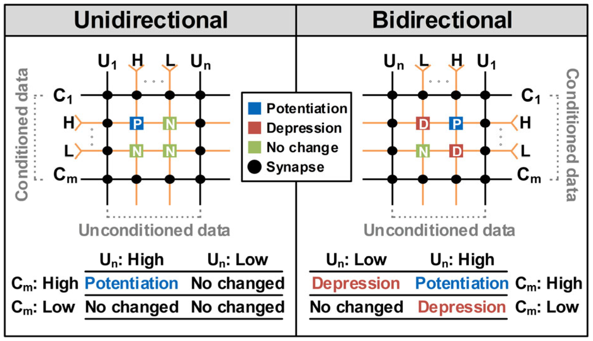
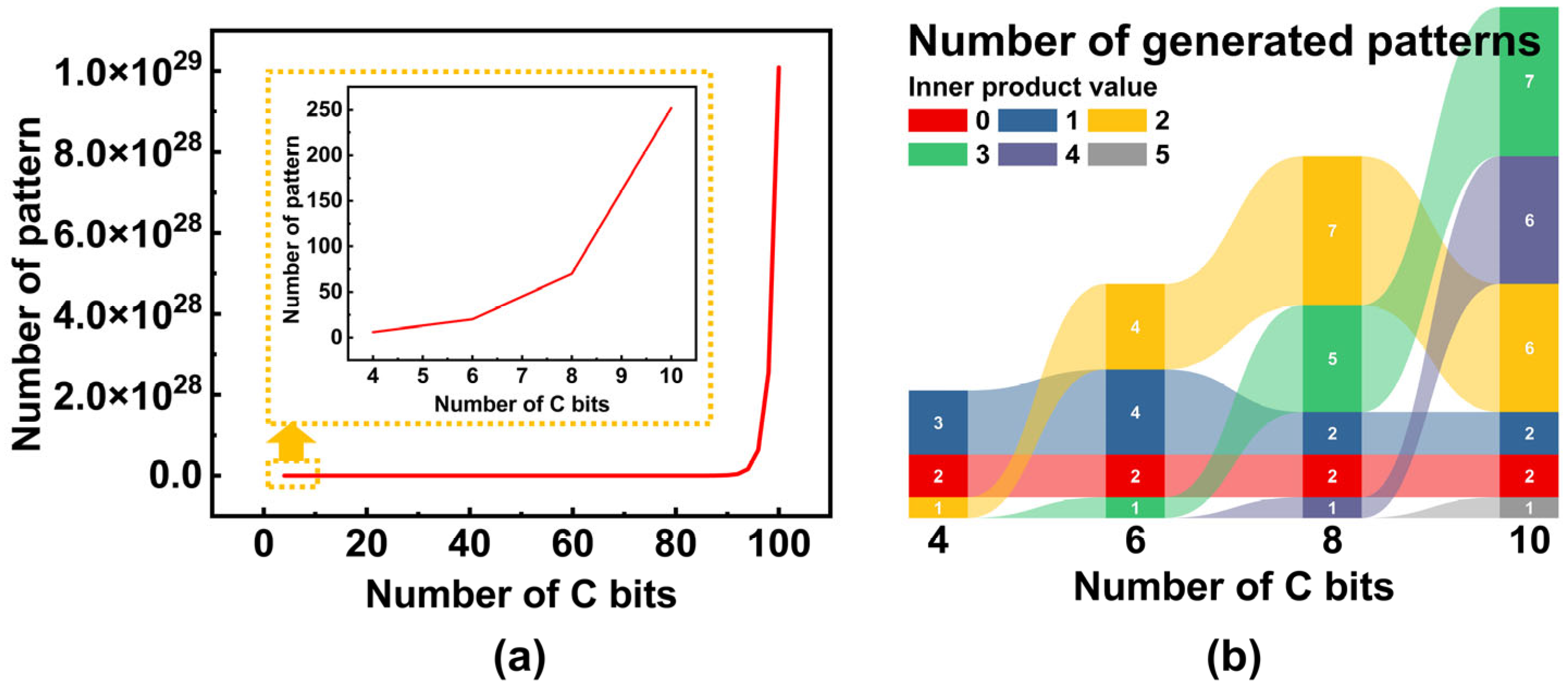
As shown in Figure 2, the methods of training synapses in pattern-associative learning can be largely divided into two types [16] (pp. 815–829). The first method is a unidirectional structure, where synapses are updated only when conditioned and unconditioned stimuli are simultaneously applied. In this case, only potentiation occurs, and thus the state of the synapse changes exclusively toward decreasing resistance, thereby strengthening the connectivity between nodes [17,18,19,20,21]. The second method updates the synaptic state not only when conditioned and unconditioned stimuli are applied simultaneously but also when either stimulus is applied individually. When both stimuli are applied simultaneously, potentiation occurs. In contrast, when either the conditioned or unconditioned stimuli are applied, depression occurs. Depression drives the synapse into a high-resistance state, thereby weakening the connectivity between nodes [17,18,19,20,21]. When neither stimulus is applied, the synaptic state remains unchanged. In both mechanisms, unconditioned data (UC) is recalled by matching conditioned data (C) to stored C–UC pairs, and the memory capacity is fundamentally determined by the bit length of C. In addition, the number of HIGH elements in the conditioned input determines the number of patterns that can be generated. Specifically, if the number of bits in the conditioned input is n and the number of HIGH elements is k, then the number of possible patterns is given by nCk. Accordingly, the number varies depending on n and k. When k = n/2, the resulting number of patterns is shown in Figure 3a. In other words, as the number of bits n increases, the number of generatable patterns also grows, so the memory capacity is determined by the array size, which is directly related to the capacity limitation. However, in associative learning, a more critical factor for recall performance is the correlation between inputs; that is, the inner product of the input data. As illustrated in Figure 3b, the number of patterns that can be generated from C depends on the inner product value, and in certain cases, the actual number of patterns may decrease even with increasing n. Nevertheless, the overall trend indicates that increases in both n and the inner product lead to an increase in the absolute number of patterns. Therefore, increasing the bit length of C, which expands the allowable inner-product range, enlarges the number of learnable patterns, implying that expanding the number of rows in the array increases the learnable memory capacity. This observation highlights the existence of a memory capacity limitation determined by the array size. Although a unidirectional structure is simple, its synaptic changes impose capacity limitations on the limited synapse array. For example, for a 4 × 6 array condition, when the inner product between elements of the input set is 0 or 1, the number of generatable patterns is six. As shown in Figure 4, across 500 simulations using sets of randomly generated input pairs within the same inner product range, the unidirectional structure learns an average of 3.72 patterns, whereas the bidirectional structure learns an average of 5.84 patterns. This indicates that, even with the same array size, the bidirectional structure increases memory capacity by additionally leveraging depression, whereas the unidirectional structure exhibits a stronger capacity limitation under the same learning inputs. Moreover, in the unidirectional structure, when conditioned patterns are insufficiently orthogonal (inner product above a specific threshold), repeated reinforcement of shared components leads to interference. This reduces pattern separability and decreases learning performance, thereby making the capacity problem more severe [16,22,23].

2.2. Python-Based Verification of Bidirectional Mechanism in Diverse Synaptic Environments

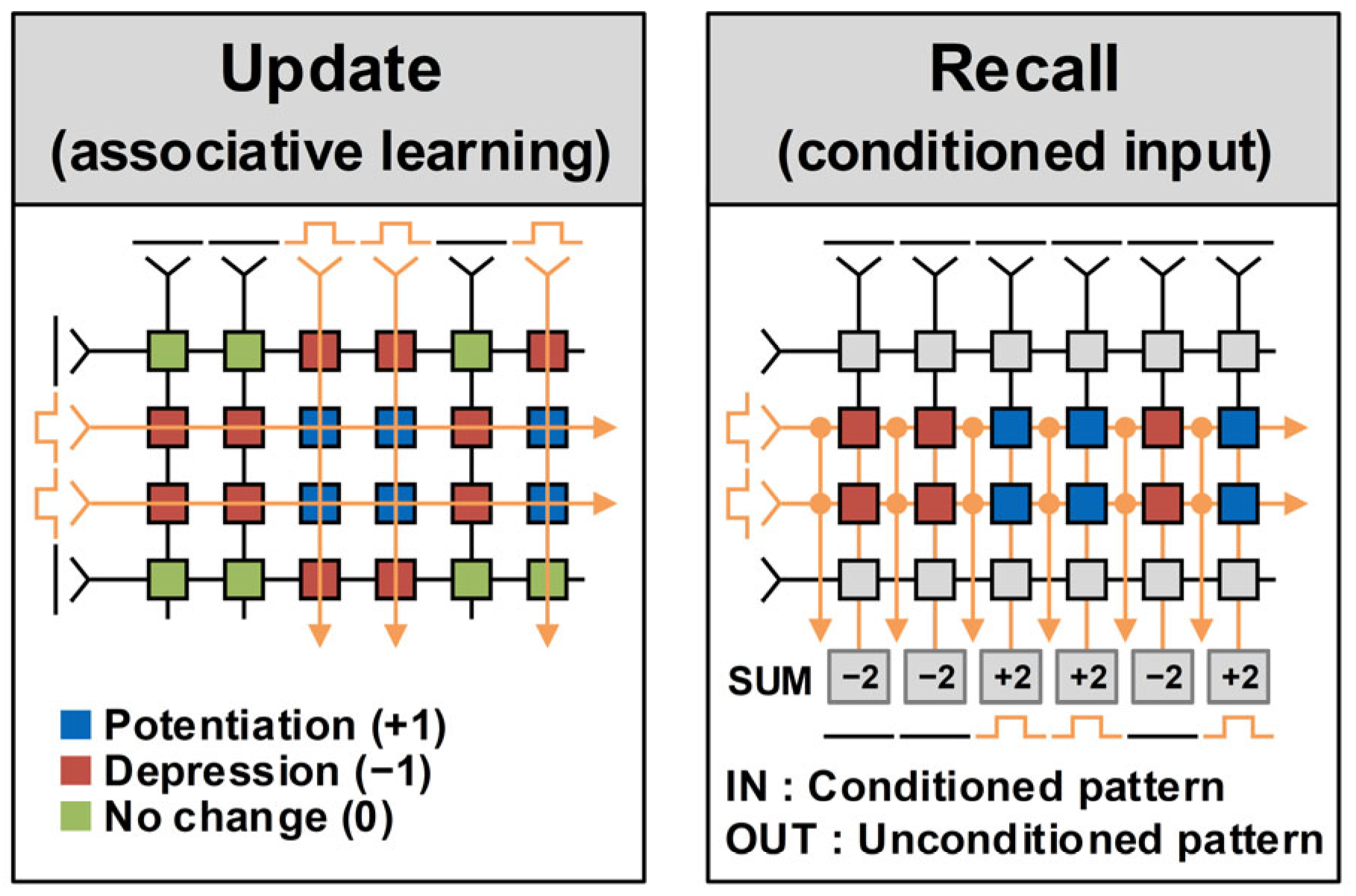
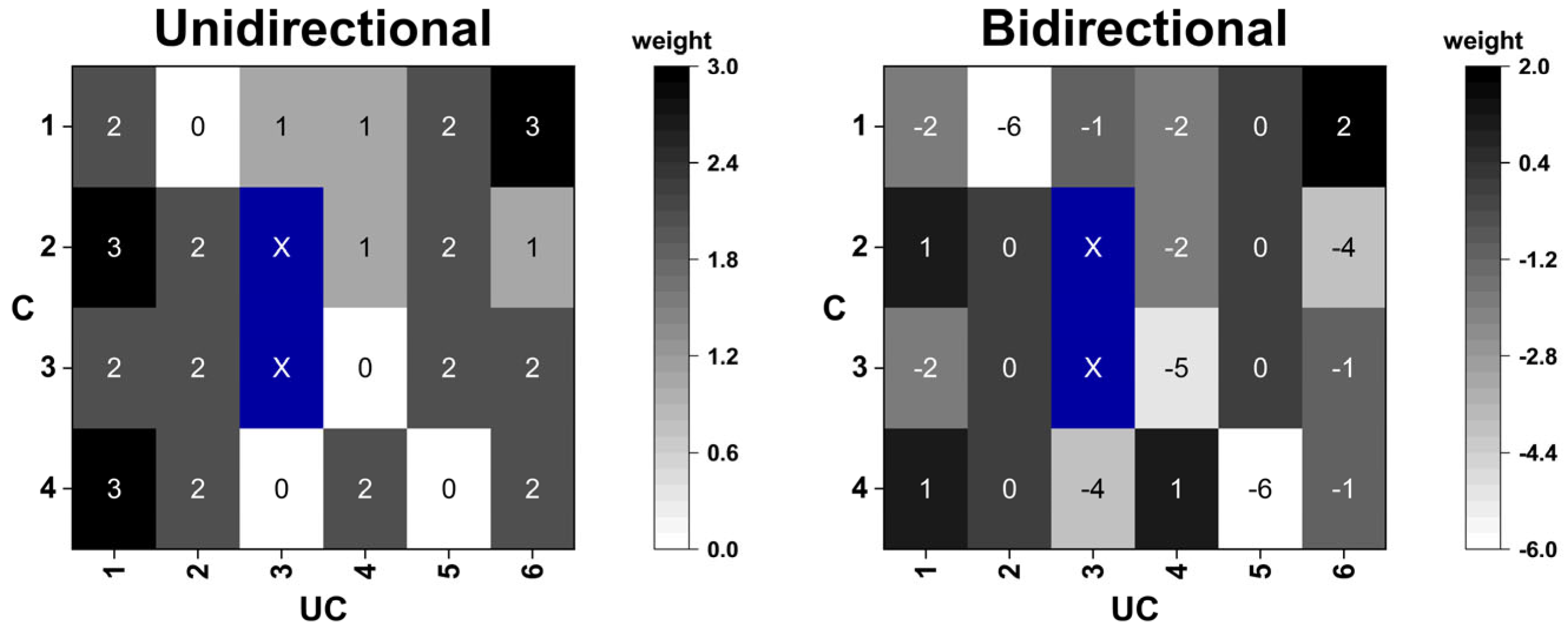
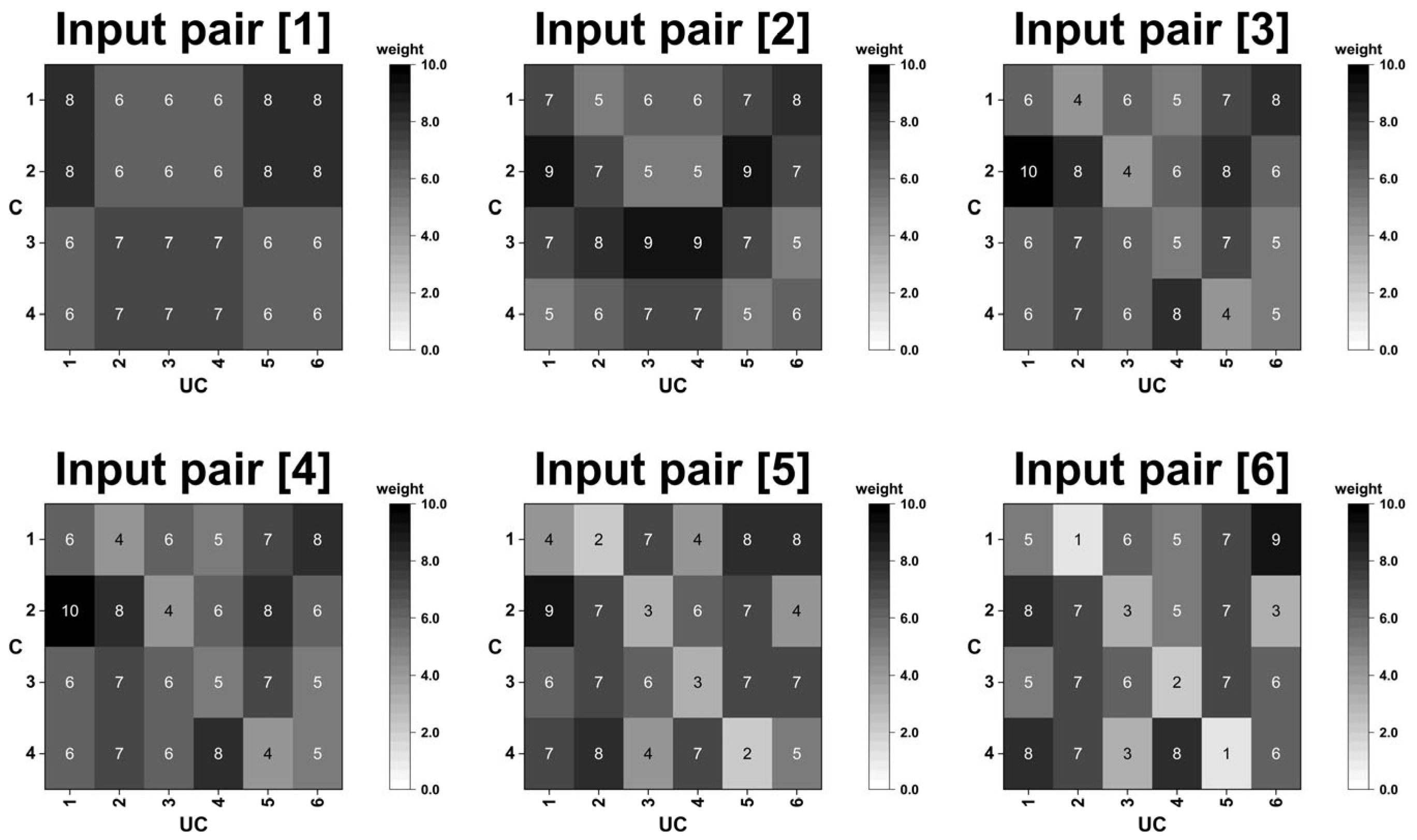
In this study, a Python-based (Python 3.12) simulation was conducted to evaluate whether the bidirectional mechanism achieves more effective recall of unconditioned patterns from conditioned patterns after associative learning than the unidirectional mechanism. The operational procedure is illustrated in Figure 5. Learning was performed on a matrix regarded as a synaptic array, where the rows correspond to conditioned inputs and the columns to unconditioned inputs. During the update process, potentiation increased the synaptic state by +1, depression decreased it by −1, and no change left the synaptic state unaltered. The updated synaptic values were subsequently stored in a 4 × 6 matrix. Accordingly, when the six input pairs listed in Table 1 were trained, the cumulative synaptic state matrix was obtained. Using this approach, both the unidirectional and bidirectional structures were trained, starting from an identical initial synaptic state (‘0’) for all synapses. The results were then evaluated by applying conditioned patterns to verify whether the corresponding unconditioned input patterns were successfully reproduced and to compare the performance differences between the two structures. In the proposed simulation, the synaptic weight states updated through potentiation and depression were represented as integers rather than resistance values. Larger values corresponded to the low-resistance state (LRS), whereas smaller values indicated the high-resistance state (HRS). In other words, increasingly positive values reflected a progressive transition toward the LRS, while increasingly negative values reflected a transition toward the HRS. Learning in the proposed architecture is determined by how many times and in which direction (+1/0/−1) potentiation or depression occurs, not by the size of a single-state change. Therefore, the integer states obtained in the Python-based simulation accurately reflect the occurrence counts of potentiation and depression, and can thus be regarded as faithfully reproducing the essential learning behavior. As shown in Figure 6, the synaptic array obtained after training reveals that, in the unidirectional structure, only potentiation can occur, so the synaptic weight states either remain fixed or increase in the positive direction. In contrast, in the bidirectional structure, depression can also occur, allowing the states to decrease, and consequently negative synaptic state values are observed. After training, each conditioned pattern was applied to the synaptic array.
The synaptic state values at the nodes overlapping with the input were summed, and this sum was defined as the SUM value, as shown in Table 2. In the Python simulations, the firing behavior of neurons in the CMOS-based system was predicted using the SUM value of the synapses state to simplify the model, since under the proposed learning architecture, variations in the SUM value mirror variations in current (a larger SUM implies greater current flow). Because the unconditioned input was represented as a 3-hot code, the three largest SUM values were set to 1 and the others to 0. This procedure corresponds to top-k (k = 3) hot code (T3H1) encoding, where the top k values are assigned 1, as presented in Table 2. In neuromorphic neural networks, a lower synaptic resistance delivers a larger current to the neuron membrane. This current accelerates the rise of the membrane potential, thereby increasing the neuronal firing rate. Reflecting this biological characteristic, the simulation was simplified by interpreting larger summed synaptic state values (SUM values) as faster neuronal firing. In other words, the magnitude of the synaptic weight state was directly mapped to the neuronal firing rate. Based on this process, when conditioned patterns are applied to the trained synaptic array, the firing patterns of the neurons can be inferred from the cumulative summed values of the connected synapses. Among the six neurons, defining the three with the highest firing rates as 1 and the others as 0 yields a pattern equivalent to the T3H1 representation. Finally, the generated T3H1 pattern was compared with the unconditioned pattern of the same label. In other words, associative recall was evaluated by verifying how accurately the corresponding unconditioned pattern could be reproduced using only the conditioned pattern.
In Table 2, “Hit” denotes whether the output pattern generated by the conditioned pattern was identical to the corresponding unconditioned pattern. As summarized in Table 2, the unidirectional structure recalled only four of the six patterns after training, whereas the bidirectional structure successfully recalled all six patterns.
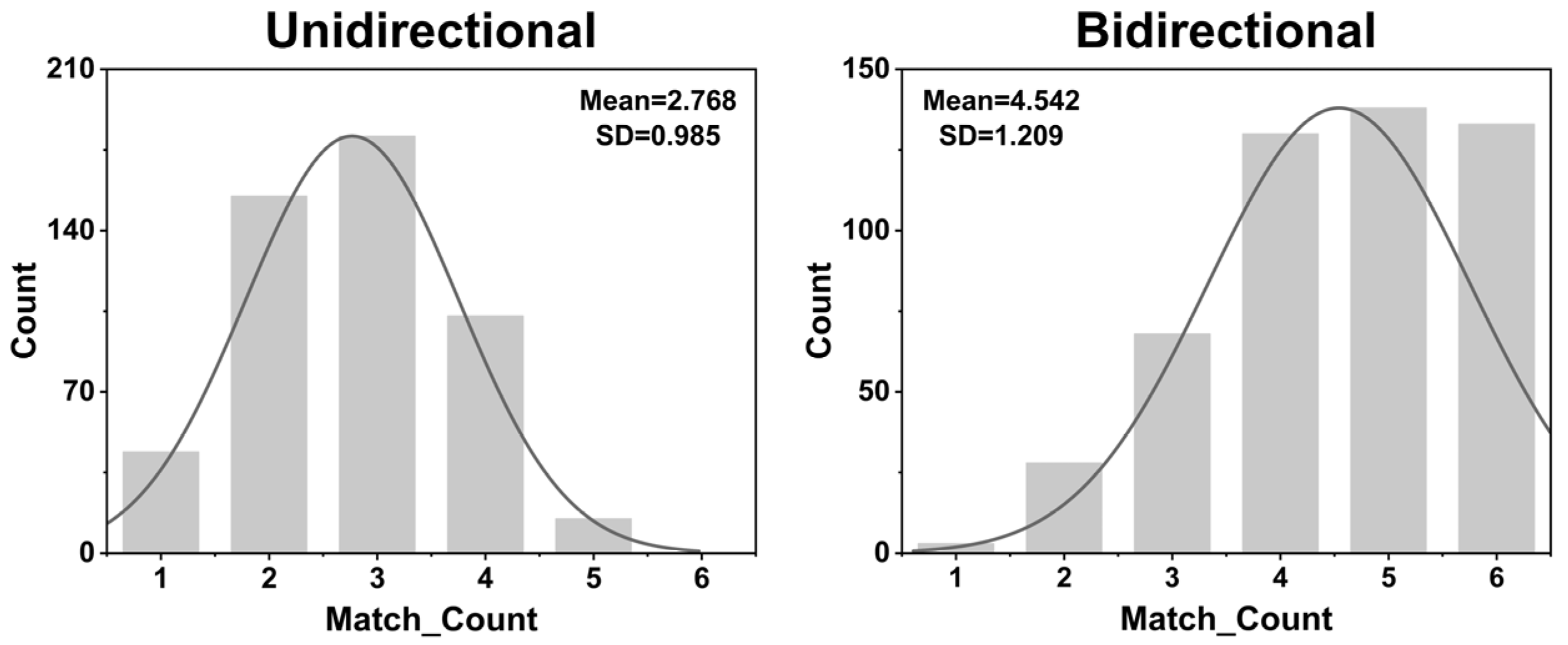
To emulate biologically plausible conditions, such as partial synapse loss and noisy initial synaptic weight [24,25,26], simulations were also conducted under conditions where some synapses were removed and the initial synaptic weight states were randomized to mimic noise. As depicted in Figure 7, the synaptic state after learning was evaluated under partially impaired synaptic array. Table 3 summarizes the resulting performance. The results demonstrate that even with the partial removal of synapses, most of the learned patterns can still be reliably recalled. Erroneous outputs appeared only in a subset of patterns for both the unidirectional and bidirectional structures. As shown in Figure 8, a histogram of the associative learning results was obtained over 500 trials, in which synapse loss was introduced at randomly varying locations for each trial. The match count reflects how many of the six conditioned patterns correctly recalled their respective unconditioned patterns, thereby serving as a measure of learning performance. The results demonstrate that, in the unidirectional structure, cases with a match count of 6 were rarely observed, whereas in the bidirectional structure, the same match count was observed more than 100 times. On average, the unidirectional structure recalled approximately 2.76 patterns, whereas the bidirectional structure recalled approximately 4.54 patterns.
When expressed as the error rate (ERR) with respect to the total number of patterns, the error rate is defined as follows:
E R R = 1   M N  
where N represents the total number of patterns and M represents the average number of correctly recalled patterns. When the results of the two conditions (unidirectional and bidirectional) are denoted as ERR1 and ERR2, respectively, the relative improvement (RI) is defined as follows:
RI = (ERR1ERR2)/ERR1 × 100%
For the case of N = 6, M1 = 2.76, and M2 = 4.54, the error rates for each condition are calculated as ERR1 = 1 − (2.76/6) ≈ 0.54 (54%) and ERR2 = 1 − (4.54/6) ≈ 0.243 (24.3%).
Accordingly, the absolute error reduction was calculated as follows:
ΔERR = ERR1ERR2
Based on this, the absolute error reduction is given by ΔERR = 0.54 − 0.243 = 0.297 (29.7%p), and RI = (0.54 − 0.243)/0.54 × 100 ≈ 55.0%. The bidirectional structure achieves an approximately 55% improvement in the error rate compared with the unidirectional structure. In other words, the bidirectional structure demonstrated superior recall ability compared with the unidirectional structure under impaired-synapse conditions. In biological memory, removing a crucial cue severely impairs recall, whereas losing less important parts has minimal impact. Consistent with this, the standard deviation (SD) reported in Figure 8 varies with the importance of the lost synapses, increasing or decreasing accordingly. Such SD variation is observed in both unidirectional and bidirectional cases. In the proposed bidirectional architecture, the loss of certain synapses can rarely result in very low match counts (e.g., match_count = 1), which broadens the distribution and makes the SD appear larger. In contrast, because match_count = 6 (perfect match) never occurs in the unidirectional case, the upper bound is restricted, which narrows the distribution and yields a smaller SD. Therefore, the principal indicators of recall performance are not SD itself but the mean performance and the probability of attaining higher match counts. Under identical conditions, Figure 8 shows that the bidirectional case has a higher mean match_count and the probability of achieving multiple matches (match_count = 4–6) is 80.2% for the bidirectional case, compared with 2.6% for the unidirectional case.
To emulate an environment with synaptic noise, the synaptic array was initialized to a random state and evaluated through Python-based validation simulations.
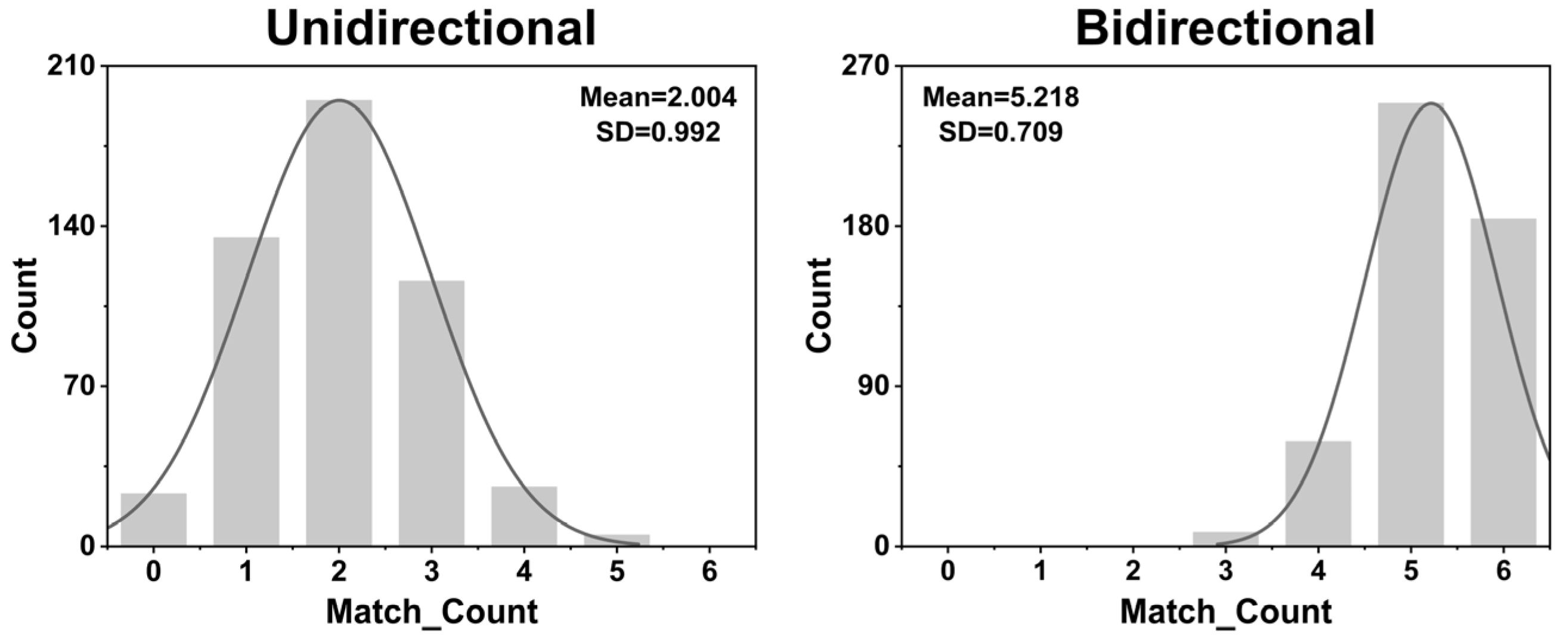
Figure 9 presents the synaptic state maps obtained by training the unidirectional and bidirectional structures with randomized initial synaptic weight states to emulate noise in the synapses. The corresponding performance is summarized in Table 4. Under these noisy conditions, the unidirectional structure recalled only two patterns, whereas the bidirectional structure successfully recalled all patterns. As presented in Figure 10, a histogram of the distribution over 500 simulation runs, in which each initial synaptic state was assigned a different random configuration. The unidirectional structure exhibited a distribution concentrated at low match counts, whereas the bidirectional structure demonstrated a distinctly right-shifted distribution. On average, the unidirectional structure recalled only 2.00 patterns, whereas the bidirectional structure recalled 5.21 patterns.
The error rates were calculated as ERR1 = 1 − 0.3333 ≈ 0.6667 (66.7%), and ERR2 = 1 − 0.8683 ≈ 0.1317 (13.2%). Accordingly, the absolute error reduction was ΔERR = 0.535 (53.5%p), and the relative improvement was RI = (0.6667 − 0.1317)/0.6667 × 100 ≈ 80.3%. These results confirm that the bidirectional structure achieves an approximately 80.3% performance improvement over the unidirectional structure under noisy conditions. The primary reason that the bidirectional architecture histogram results appear “saturated” under noisy synaptic arrays is the small array size. In a small array (4 × 6 in this study), the number of patterns to be learned is limited, and under ideal synapses the system achieves sufficiently high recall accuracy and stability to learn nearly all patterns. In other words, owing to the small array size, the learning set is restricted to six patterns, the inherently high accuracy in the ideal-synapse condition prevents substantial performance degradation in the presence of noise, producing a saturation-like distribution.
In the current system, recall performance is evaluated using match_count. For some input groups, synapse-loss may yield a higher match_count than noise for the same input. However, when comparing averages over 500 trials, Figure 8 (representing synapse loss) shows an average of 4.5, whereas Figure 10 (representing noisy synapses) shows an average of 5.2, indicating that noise condition provides better recall performance. This stems from the intrinsic characteristics of the scheme. Synapse loss directly severs the signal transmission path, thereby exerting a more detrimental impact on recall ability. In other words, while “noise in the remaining connections” can be partially compensated through learning to minimize its effect, “the complete loss of connections” constitutes structural damage and thus causes a more severe degradation in performance. This has been confirmed both in biological evidence [27] and in synapse-based network systems [28].

2.3. System Implementation of Pattern-Associative Learning

The proposed bidirectional pattern-associative learning circuit system was designed by adopting the Python simulation results above, which exhibited the bidirectional structure showing the lower error rates than the rate of the unidirectional structure. As shown in Figure 1, a structure with 4-bit conditioned inputs and 6-bit unconditioned inputs was implemented using a 4 × 6 processing element (PE) array, with each PE designed to support both read and update operations and including an individual synapse capable of bidirectional operations. To emulate brain-like learning in which synaptic weights are represented by spikes, a 1 × 6 neuron array was incorporated. In addition, the system was implemented with a priority detector that converts spike signals into digital patterns, thereby representing the final results in digital bit and enabling the system to distinguish patterns.
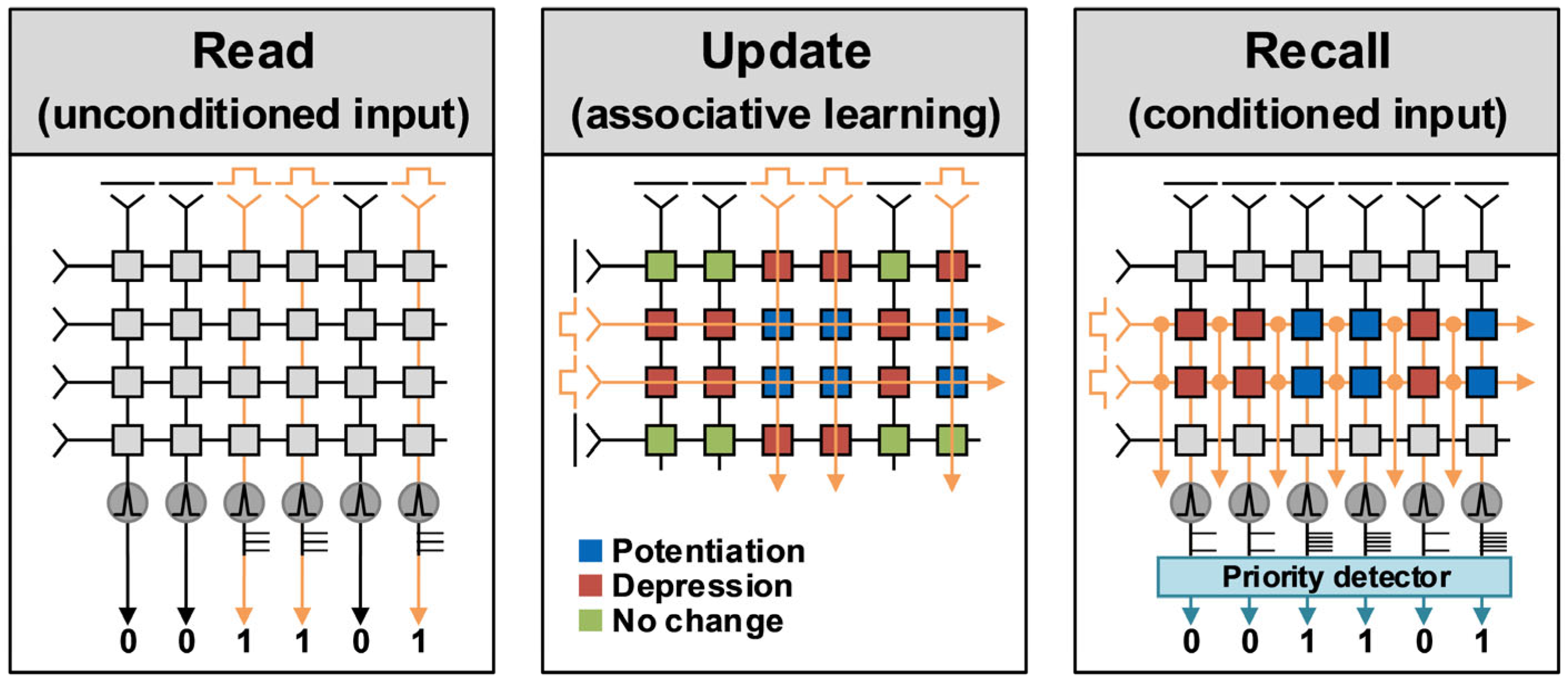
As shown in Figure 11, the system operation can be classified into three distinct modes. First, in the read mode, the unconditioned input signal is applied to evaluate the neuronal firing response. In this mode, a signal is applied when the input pattern is “1” and not applied when it is “0,” such that the neuronal firing directly reflects the given unconditioned input pattern. The synaptic array of the proposed system is organized such that each vertically connected synapse shares a common post-synaptic neuron membrane. Consequently, the amount of current flowing through the synapses varies depending on the applied unconditioned pattern, which modulates the neuronal firing rate and determines the output spike pattern. In addition, in the read mode, no synaptic state changes occur, even when only the unconditioned input is applied, since depression from the bidirectional mechanism is suppressed. Second, in the associative learning update mode, neuronal firing does not occur and only the synaptic state is updated. Under the bidirectional rule, single-input stimulation (US or CS) induces depression, co-presentation of US and CS induces potentiation, and no stimulation leaves the synaptic state unchanged. In the proposed system, the bidirectional architecture may appear analogous to spike timing-dependent plasticity (STDP) in that both potentiation and depression occur. However, STDP determines potentiation or depression from the interval between pre- and postsynaptic spikes, such that spike timing carries the important information [29]. But the bidirectional architecture in the proposed system serves a different purpose. It stores the association between simultaneously presented conditioned and unconditioned inputs in the synaptic weights, enabling pattern restoration and recall. Because weight updates are governed by the correlation of the input pair under co-presentation rather than by the spike-timing difference (Δt), the method is clearly distinct from STDP. Third, in the recall mode, a conditioned input is applied after associative learning to retrieve the corresponding unconditioned input pattern. When a conditioned input is applied, the firing frequency of the post-synaptic neuron changes according to the states of the synapses. Consequently, the 1 × 6 neuron array produces a 6-bit output spike pattern corresponding to the conditioned input. The recall performance was verified by evaluating the correspondence between the generated spike pattern and the original unconditioned input patterns. In this stage, the priority detector measures the neuronal firing frequency and converts it into binary values (0 and 1), enabling the reproduction of the binary pattern identical to the unconditioned input. In the recall mode, as in the read mode, applying only the conditioned input causes no synaptic state transitions. Figure 12 illustrates the detailed schematic of the PE and priority detector blocks. The operation of the PE in the read and recall modes is as follows: when a READ pulse is applied, the output signal of OR gate, driven by the conditioned and unconditioned input pulses, is transmitted along the orange line node. In this configuration, the top node (TOP) of each synapse is connected to the pulses delivered from either the conditioned or unconditioned inputs, whereas the bottom node (BOT) is connected to the neuron membrane. Thus, the current flowing into the membrane varies according to the resistance state of the synapse. Synaptic updates are controlled by the control signals of the MUX. When both the unconditioned and conditioned inputs are applied simultaneously, the AND gate generates a signal that sets the first bit of the MUX to high. In this case, the MUX state becomes [1][0], and when VUPDATE = VTOP − VBOTTOM, TOP and BOT are set to VPOTENTIATION and VSS, respectively, resulting in VUPDATE = VPOTENTIATION. In contrast, when only the unconditioned or conditioned input is applied, the XOR gate generates a signal that sets the second bit of the MUX to high, whereas the first bit is set to low. In this case, the MUX state becomes [0][1], with VSS and VDEPRESSION applied to TOP and BOT, respectively, resulting in VUPDATE = −VDEPRESSION. Through this mechanism, the synaptic update is executed. The current determined by the updated synaptic state modulates the neuronal firing frequency, and the resulting spike signals are subsequently digitized through the priority block. As illustrated in Figure 12, the proposed priority detector comprises three functional blocks: an interval detector, a minimum pulse detector, and a pulse equalizer. The interval detector senses incoming spike events and generates Q[N] signals, where the pulse width is defined by the interval between the positive edge of the read pulse and the positive edge of the second spike of the neuron. Thus, neurons with higher firing rates produce shorter pulse widths, whereas neurons with lower firing rates yield longer pulse widths. Subsequently, the minimum pulse detector groups the Q[N] signals and performs logical AND operations to reliably extract the minimum pulse, enabling the circuit to identify the dominant neuronal activity. The key idea of the proposed minimum pulse detection scheme is to reliably identify the dominant neuronal activity by selecting only the top-k shortest pulses among n input bits. By tuning the group size r according to the number of active inputs (k) from the unconditioned pattern, the detector adaptively selects the dominant short pulses. To guarantee that only the top-k shortest pulses are chosen, the group size must satisfy
r = nk + 1
In this study, with n = 6 and k = 3, we obtain r = 4. Grouping the six inputs into subsets of four yields
C 4 6 = 6 4 = 15
which represents the number of ways to choose four channels out of six. From these 15 candidate subsets [PQ], the minimum pulse detector ensures that the resulting pulse widths are restricted to the three shortest values. In other words, depending on k, the resulting pulse widths can be determined by the two or four shortest pulse widths. Subsequently, the pulse equalizer compares each candidate signal [PQ] with the original signal Q[N] to determine the neuron responsible for generating the shortest pulse and maps this result onto the final output. When a PQ signal corresponds to a Q[N], the associated FP[N] is set to HIGH. Otherwise, it remains LOW. This hierarchical architecture ensures the reliable extraction of dominant neuronal signals without reliance on area-intensive data converters, thereby providing improved area and power efficiency for the systems.

2.4. Implementation of Synapse and Neuron for Associative Learning

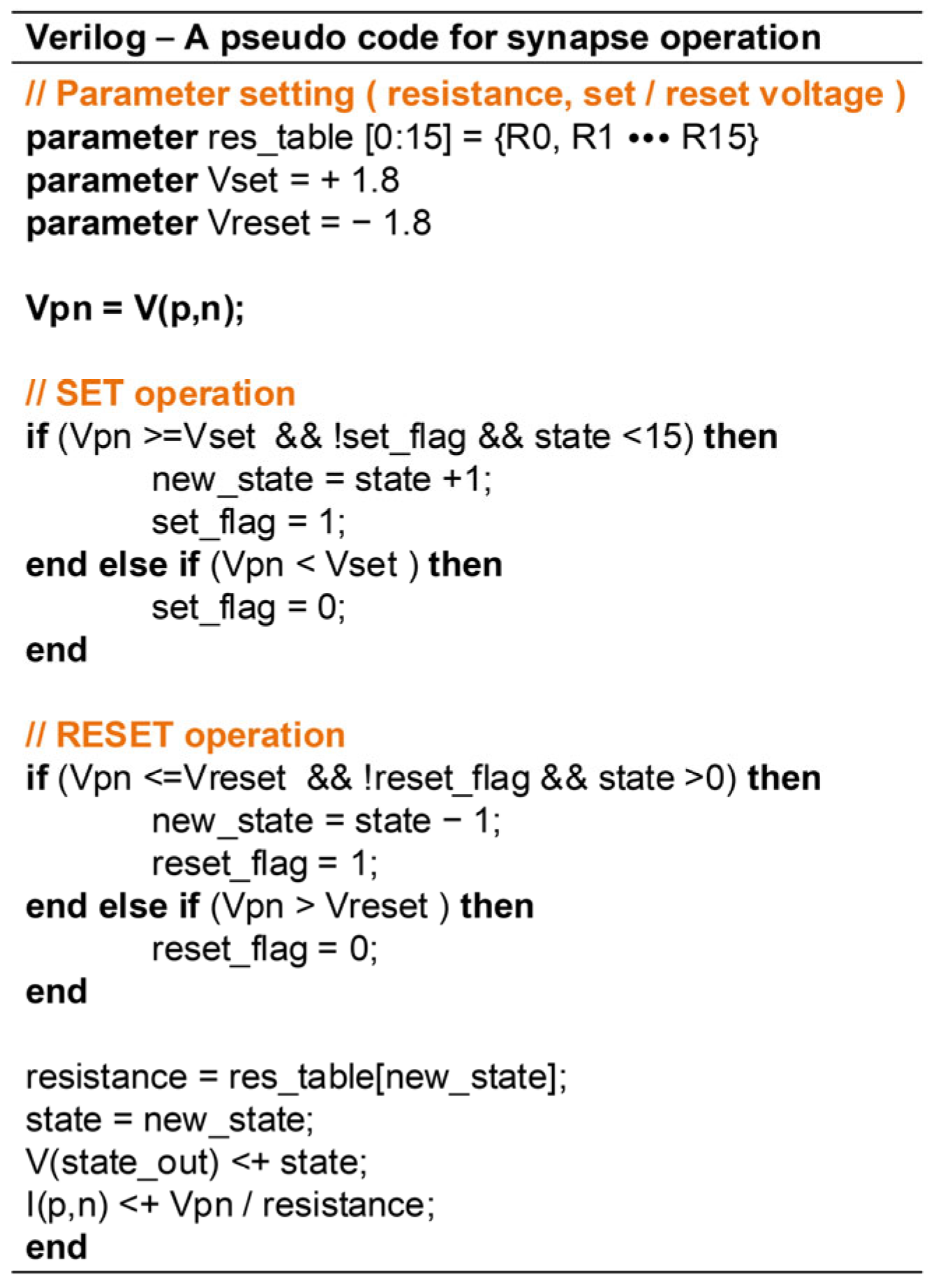
For system verification and result extraction, synapses were implemented in Verilog-A models. Several Verilog-A models for emulating synaptic behavior have been reported [30,31,32,33,34]. However, most of these models are structurally complex because they explicitly describe target device physics. In the proposed system, the synaptic functions most critical to associative learning are cumulative updates with state retention, synaptic weight potentiation and depression, and voltage-to-current conversion. These functions can be more effectively realized through a simple behavioral implementation rather than through detailed complex synaptic device modeling. Accordingly, as shown in the pseudocode presented in Figure 13, a simplified Verilog-A model was developed to emulate only the essential synaptic behaviors rather than relying on device-based implementations. In this model, the synaptic state changes progressively as the number of applied update pulses increases, consistent with the pulse-test characteristics observed in actual synaptic devices [35,36]. Furthermore, the model allows precise specification of the update voltage and resistance states. This enables systematic definition of resistance modulation during state transitions and the corresponding voltage thresholds for updates.
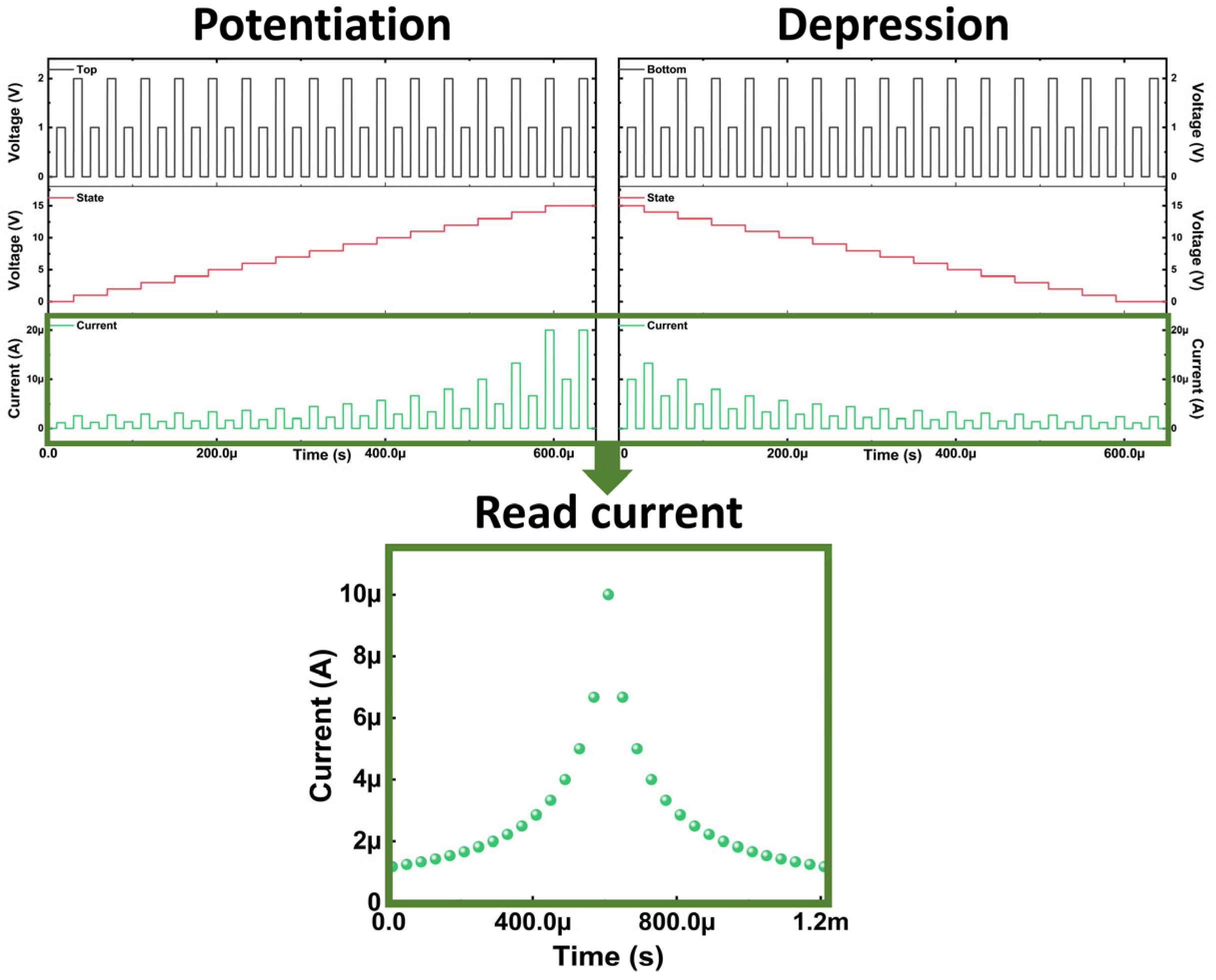
In addition, the initial state can be freely configured, facilitating the emulation of randomized synaptic conditions and thereby enhancing the versatility of the model for system-level testbench evaluations. Figure 14 presents the operational characteristics of the implemented synapse. When an update pulse is applied to the top node, potentiation occurs, thereby increasing the synaptic state and flowing current. In contrast, applying the update pulse to the bottom node induces depression, which decreases the state and current. During this process, the update pulse train comprises alternating update and read pulses, where the read pulses correspond to low-voltage stimuli that do not trigger synaptic updates and are used only for reading the synapse condition. These results indicate that the proposed Verilog-A synapse model not only supports voltage-driven synaptic updates but also successfully reproduces and validates the pulse-test characteristics of actual synaptic devices.
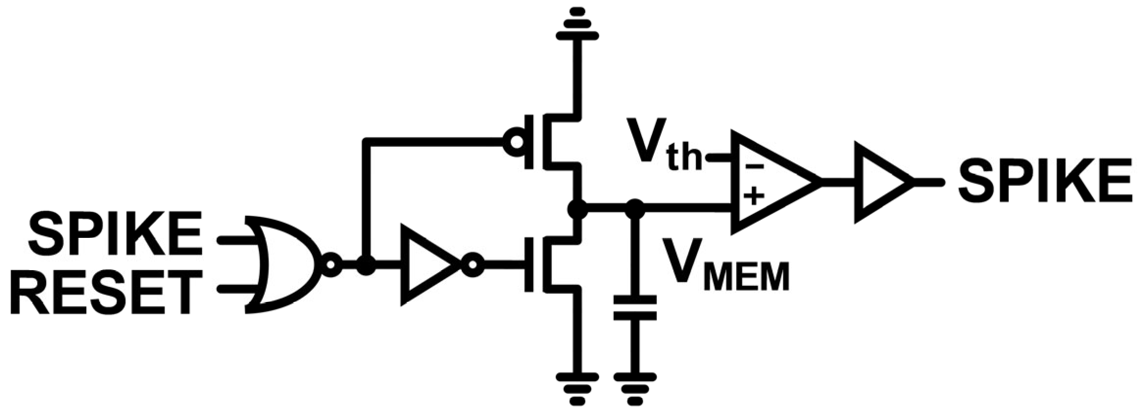
As shown in Figure 15, the neuron used in the proposed system is based on an integrate-and-fire circuit, adopting a simplified Mihalas–Niebur structure [37,38] that is designed to perform only the integrate-and-fire operation. This neuron operates as a comparator-based neuron, where a spike is generated once the membrane voltage VMEM exceeds the threshold voltage Vth. Upon spike generation, the membrane potential is immediately reset to ground, thereby terminating the firing event.

3. Results and Discussion

3.1. Cadence Simulation Results of Overall System Operation Under Ideal Synapse Condition

The proposed system was designed using a 180 nm process design kit (PDK) and simulated at the schematic level in the Cadence environment (IC 6.1.8). As shown in Figure 16, in the read operation, the spike patterns of the post-synaptic neuron array are observed when the unconditioned input is applied. In the proposed system, the unconditioned input consists of six bits (UC1 to UC6), indicating that each one corresponds to one bit. At this stage, because the associative learning function is not activated, the unconditioned input pattern and post-synaptic neuron output spike (POST1 to POST6) pattern have a simple one-to-one mapping relationship. For example, if the unconditioned input pattern is UC [1:6] = 100011, the post-synaptic neuron firing pattern also appears as POST [1:6] = 100011.
Figure 17 illustrates the evolution of the synaptic state in the Verilog-A implementation under the defined learning mechanism.
During the update phase, potentiation was induced when the conditioned pulse (C1) was applied in conjunction with either of the unconditioned pulse (UC1 or UC6), resulting in increased synaptic states of S11 and S16, respectively, whereas individual application of either pulse resulted in depression with a decreased synaptic state. In non-update periods, the synaptic state remains unaffected by either the conditioned or unconditioned pulse, demonstrating that learning updates are confined to the defined update intervals. As presented in Figure 18, the synaptic array state is represented as a heat map during the learning of successive unconditioned and conditioned pattern pairs. As learning progresses with the addition of each new pattern, the synaptic weight states become progressively diversified. As depicted in Figure 19, the neuron spike response to a conditioned input differs between before and after learning. The red graph indicates the firing of the first post-synaptic neuron for the third input pair, and the green graph indicates the firing of the fourth post-synaptic neuron for the fifth input pair. Before learning, the spike frequencies of the first and fourth neurons were the same. However, after learning, the synapses connected to the first neuron that intersected with the input were strengthened (potentiation), resulting in more spikes within the same ΔT interval (10 µs) and an increased frequency. In contrast, the synapses connected to the fourth neuron was weakened (depression), resulting in fewer spikes and a decreased frequency.
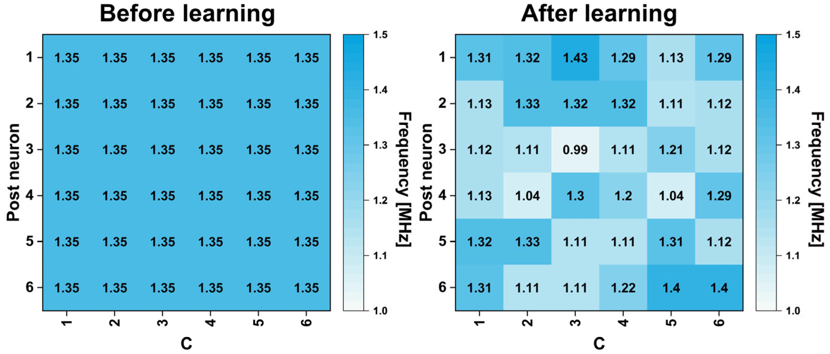
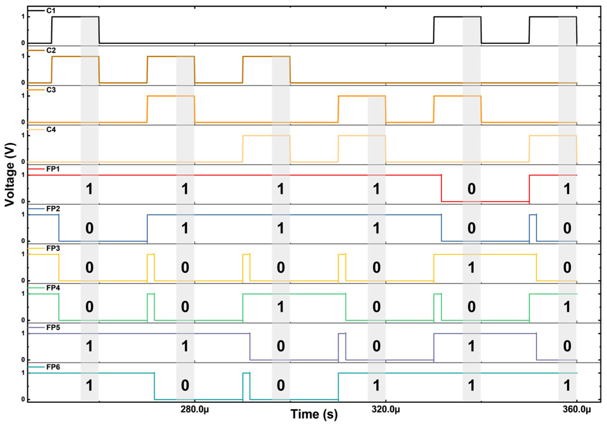
Figure 20 shows the firing patterns of the post-neurons depending on the learning states. Before learning, all conditioned input patterns elicited the same firing frequencies across the neurons. However, after learning, specific neurons exhibited dominant activity for each input, resulting in the formation of distinct firing patterns. These changes in the spike activity are further processed by the priority detector, which converts the firing frequencies into digital bit representations. As shown in Figure 21, the three neurons with the highest firing frequencies for each input are encoded as “1,” whereas the others are encoded as “0,” thereby forming the final output bitstream. Figure 22 compares the spike patterns acquired after learning operation with those originally elicited by the unconditioned input. The results confirm that the conditioned input alone, in the absence of the unconditioned input, produces an identical post-neuron output pattern, thereby substantiating the ability of the proposed system to perform reliable pattern recall through associative learning.

3.2. System Operation Under Conditions of Synapse Loss and Noisy Synaptic Weight States

After verifying the system operation with the synapses in the nominal initial state, additional Cadence-based circuit simulations were conducted under environments with partially lost synaptic data and randomized synaptic initial states.
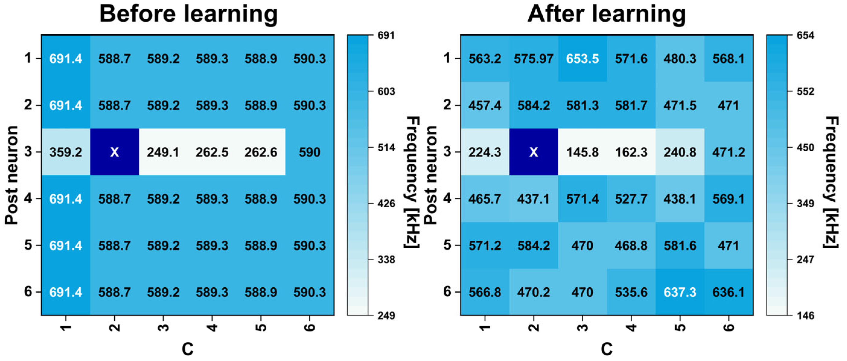
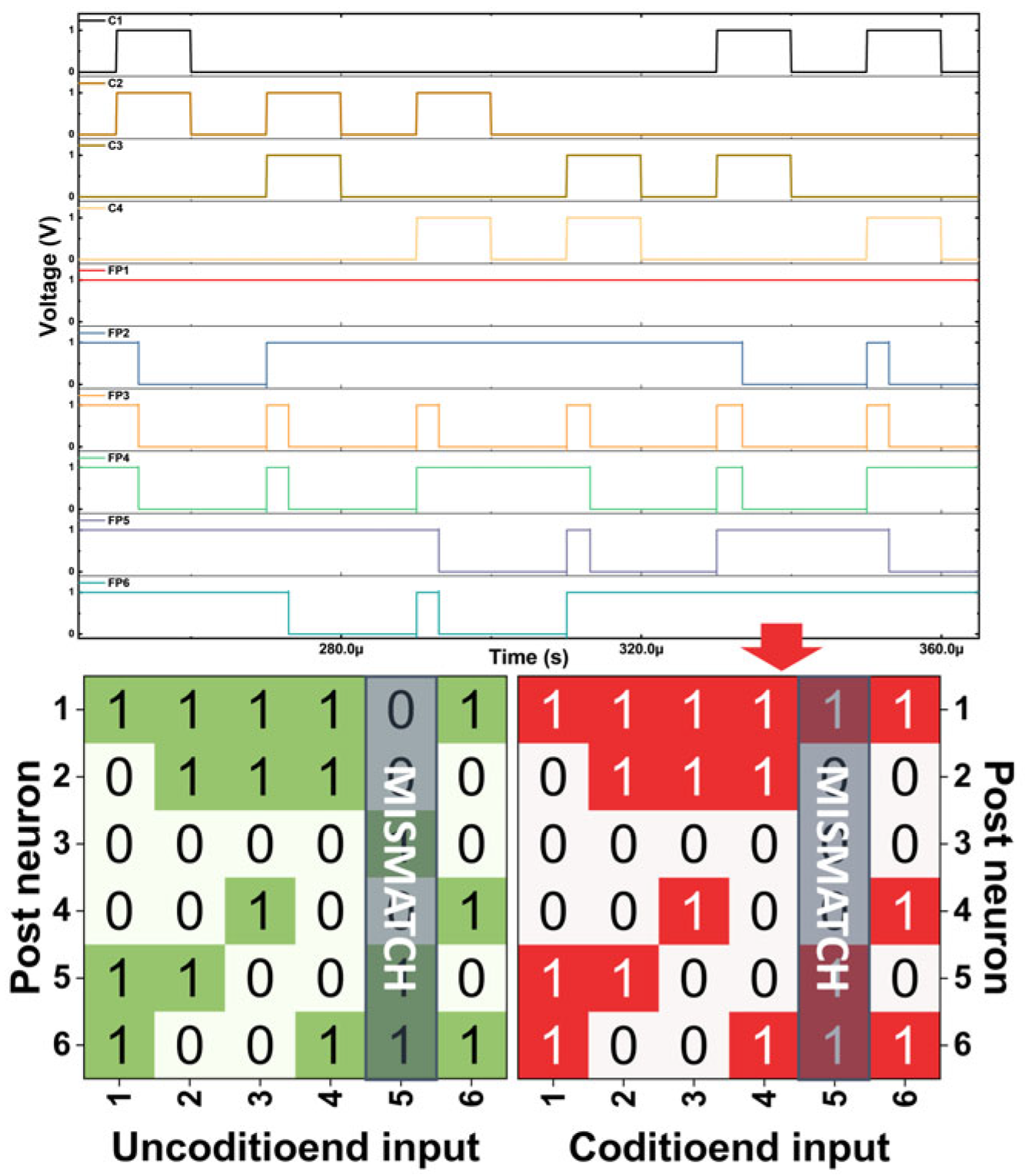
Figure 23 presents the spike responses of the post-synaptic neurons before and after learning under partial synapse loss. Before learning, aside from a few neurons whose responses were distorted by synapse loss, almost all neurons fired at similar frequencies, which made it hard to clearly distinguish different input patterns. After learning, however, the frequency distribution varied depending on the input, demonstrating enhanced discriminability and confirming the feasibility of associative recall. Figure 24 shows the final digital patterns extracted by the priority detector. Only a single mismatch was observed among all patterns, whereas in every other case the unconditioned pattern was correctly recalled from the conditioned input. These results confirm, through the simulations, that our proposed pattern-associative learning system can be achieved under synaptic degradation by employing the bidirectional update scheme.
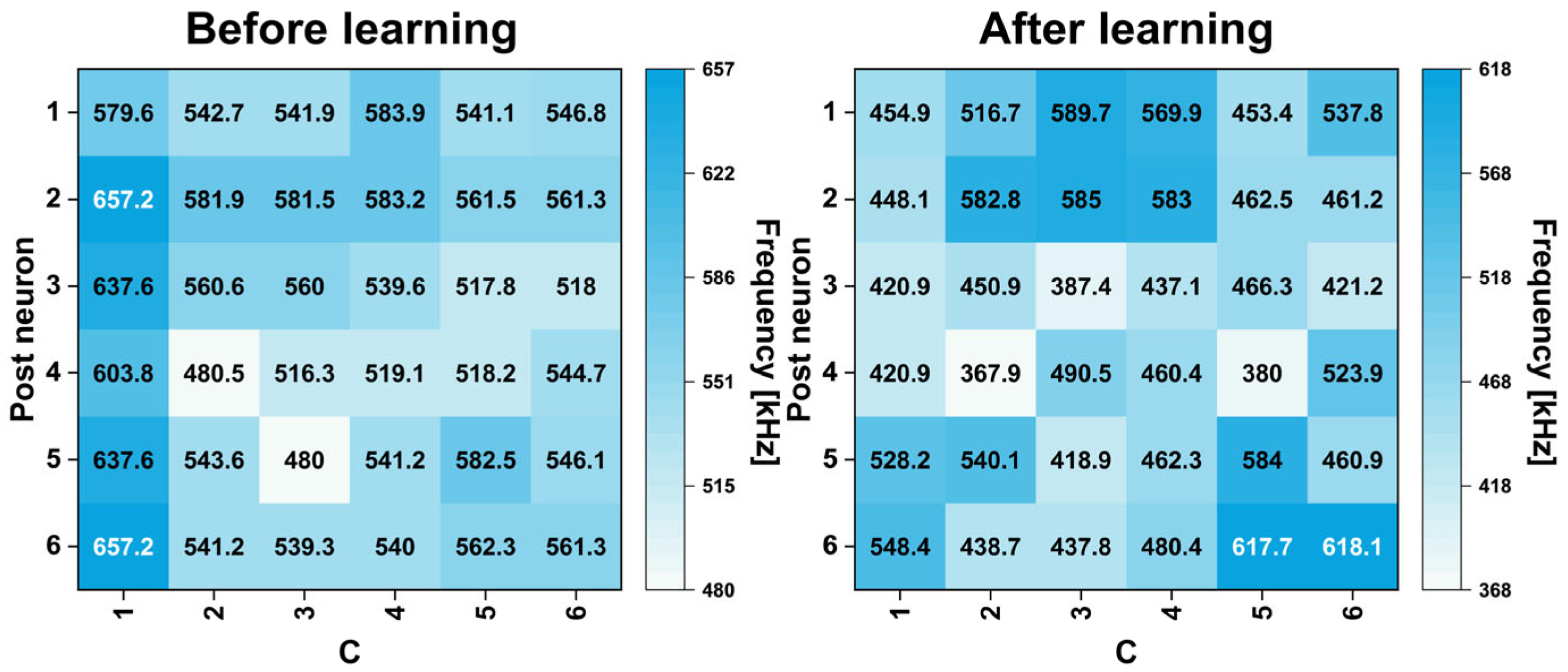
Figure 25 provides a comparative analysis of the post-synaptic neuron spike responses before and after learning under noisy initial synaptic conditions. After learning, clear patterns emerged in the frequency distribution, demonstrating that discriminability is maintained even when the initial conditions are randomized. Finally, Figure 26 presents the digital patterns extracted by the priority detector, showing that all patterns were stably learned without mismatches and that the unconditioned patterns were consistently and correctly recalled from the conditioned inputs. These findings demonstrate that the proposed pattern-associative learning system is feasible under a broad range of synaptic conditions, including normal synaptic weight states, synaptic degradation, and noisy initial synaptic weight states.

3.3. Measured Power of Proposed Associative Learning System

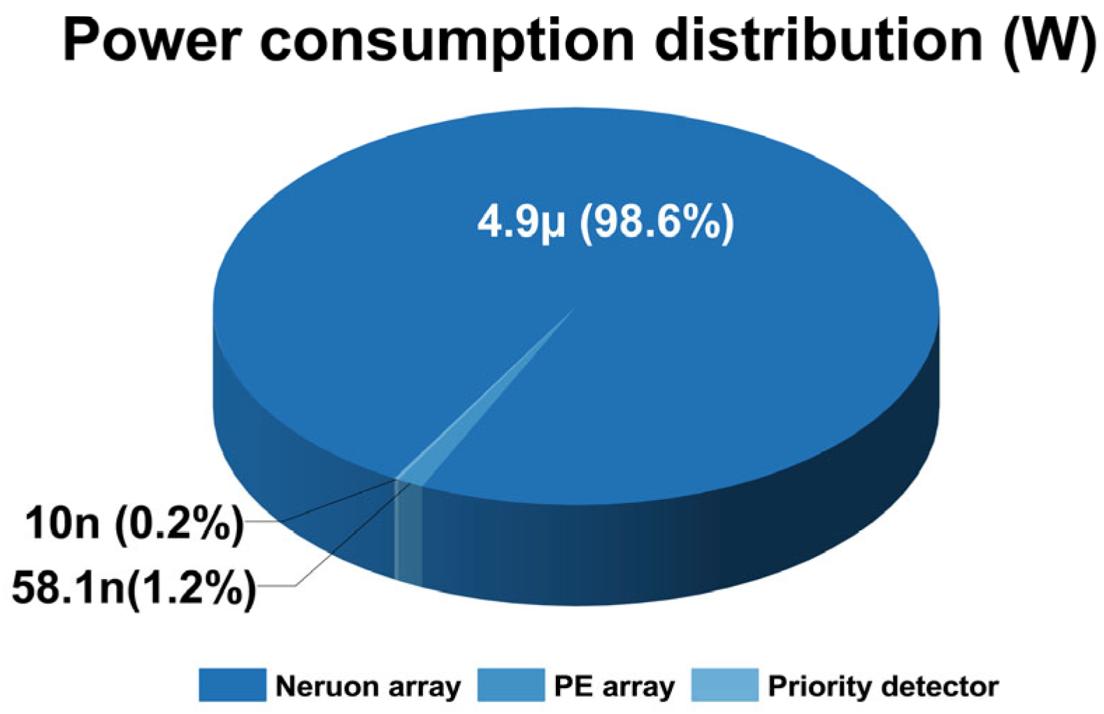
As shown in Figure 27, the total power consumption measured for the 4 × 6 configuration is 4.98 µW. The proposed system comprises three circuit blocks. During the execution of read–update–recall operations for six patterns, the neuron block consumed 4.9 µW, accounting for 98.6% of the total power.
In contrast, the processing array and priority detector consumed only 1.2% (58.1 nW) and 0.20% (10 nW), respectively, confirming that the power contribution of circuits for learning operations is minimal. Therefore, even when scaling the synapse array size, the incremental power consumption from the PE and priority detector circuits is expected to remain negligible. While the majority of the power consumption is attributed to the neuron block, this suggests that energy efficiency can be further improved by replacing the neuron block with a low-power alternative, such as a neuron circuit operating in the subthreshold regime [39,40]. In addition, this study has been validated only with modeled synapse at the small-array scale. As the array size increases, capacitive loading becomes more significant, and some neuromorphic synaptic devices exhibit excessively small LRSs, which may cause stability issues. To overcome these challenges, a dedicated driving amplifier is required [41,42,43], which inevitably increases power consumption. However, this drawback can be alleviated through the use of low-power amplifiers [44,45,46], allowing energy efficiency to be maintained even in larger arrays.
Moreover, Figure 28 shows the energy consumption of each block under learning and recall conditions for six patterns. First, the priority detector is activated by neuron spikes, and since pattern recall is determined using spike signals after associative learning, its energy consumption during recall is noticeably higher than during learning under the same conditions. For the neuron block, the static energy remains almost the same in both modes.
However, an additional increase is observed during recall due to the spikes generated in the process, leading to a slight rise compared to learning. In contrast, the PE block shows significantly higher energy consumption during learning because of weight updates, whereas in recall it is much lower. However, the PE energy in recall is not zero, because even in the read state (update-disabled), power is still required for internal switching operations such as receiving C/UC signals, selecting synaptic connection paths, and connecting or disconnecting the selected synapses to the membrane node of the neuron. Overall, the total energy consumption was 7.49 nJ for learning and 1.27 nJ for recall, showing about a 5.89× difference. In spite of this difference, both modes operated in the few-nJ range, supporting the conclusion that the system is appropriate for energy-efficient neuromorphic applications.
Beyond presenting per-block energy consumption, we computed PE energy values from DC simulations to enable a quantitative comparison between the unidirectional and bidirectional structures, as shown in Figure 29. In the proposed system architecture shown in Figure 12, the XOR block operating on U and UC that produces depression was removed, and the second control bit of the MUX was tied to ground to suppress depression node. On this basis, the PE was redesigned for unidirectional learning, and the corresponding testbench was implemented. The simulations assumed ideal synapses with no loss or noise and evaluated the learning of six patterns, as summarized in Table 1 (in the main manuscript). As a result of training with the same input patterns, the unidirectional structure generated a total of 38 updates, whereas the bidirectional structure produced 108 updates, approximately 2.8 times more than the unidirectional case. Consequently, the energy consumption of the bidirectional structure was also more than twice that of the unidirectional structure. However, the actual ratio was observed to be about 2.3. This is because the unit energy of the PE was 0.0813 nJ when only potentiation occurred, but it increased to 0.1403 nJ when both potentiation and depression occurred, so that even with twice the number of operations, the difference in unit operation energy remained below twofold. Notably, even throughout the entire learning process of six patterns, the total energy consumption of the bidirectional structure remained only at the few-nJ level. Therefore, although bidirectional learning inherently involves more operations and thus consumes more energy than the unidirectional structure, the absolute value remains small, confirming its practical applicability in neuromorphic systems where energy efficiency is of critical importance.

3.4. Examination of Memory Capacity and Recall Accuracy Under Array Scaling

In this study, the number of learnable patterns is determined by the bit length of C (n) and the number of HIGH elements (k). We considered the case n = 4 under the condition k = n/2, and conduct learning on the corresponding configurations of C.
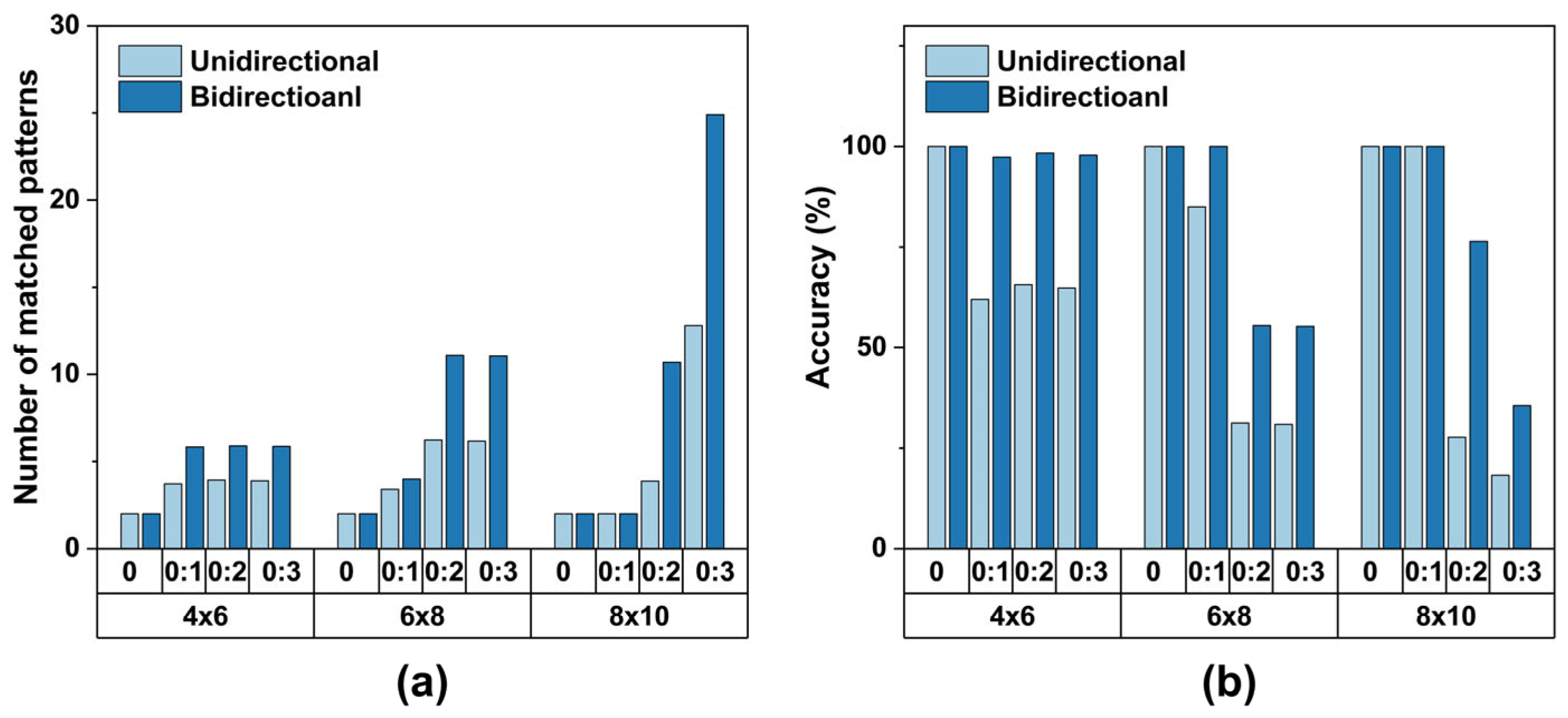
In addition, the number of patterns that can actually be generated and learned depends on the inner products (similarity constraints) among elements in the input set. In this work, we restricted the pairwise inner product to {0,1} and performed learning under this constraint. Under these conditions, the maximum number of learnable patterns is six. Accordingly, we trained on six patterns. Figure 30 illustrates how the number of generable patterns varies with array size and the inner-product constraint. The key point is that maximizing the number of patterns depends on the array size along with the inner product that accompanies that size. To achieve the maximal pattern count, the array must be large, and the element-wise inner product must simultaneously be sufficiently high. Figure 31 compares learning outcomes across unidirectional and bidirectional structures as a function of array size and the inner-product constraints {0,1}, {0,1,2}, and {0,1,2,3}. For each data point, the number of matched patterns is averaged over 50 training iterations under identical conditions, because under a fixed inner-product constraint there are many combinatorial realizations of input-pair sets that satisfy the condition. As shown in Figure 31, under the same inner-product constraint, increasing the array size does not lead to a linear increase in the number of matched patterns. In contrast, increasing the inner-product allowance in step with array size leads to a clear increase in the number of learnable patterns. Specifically, the maximal match count occurs at {0,1,2} for the 6 × 8 array and at {0,1,2,3} for the 8 × 10 array, which demonstrates a dependence of the match count on the inner-product range under array-size scaling.
Therefore, if the inner-product allowance is progressively widened during array scaling, the number of matched patterns increases steadily with array size. Conversely, despite an increase in the absolute number of learned patterns, the recall accuracy, defined as the ratio of recalled patterns to all generable patterns, does not improve in proportion to the growth in learned patterns. This finding suggests a limitation of the intrinsic Hebbian learning scheme. Nevertheless, a noteworthy point is that the bidirectional design demonstrates overall superiority to the unidirectional one in both the number of learnable patterns and the recall accuracy. To address the accuracy degradation that arises when scaling the array, we plan to introduce peripheral assist circuitry. In conclusion, this paper first demonstrates that the bidirectional architecture yields more learnable patterns than the unidirectional architecture. It then implements the scheme using simple digital gates and verifies its practical operability. Finally, we show that by applying an SNN, pattern recall after learning is achievable without complex data-converter circuitry. In summary, the key contribution of this work is the simulation-based validation that the proposed architecture simultaneously achieves simplicity of implementation and functional feasibility.

4. Conclusions

In this study, a bidirectional pattern-associative learning system was proposed and implemented using a 4 × 6 PE array with Verilog-A synapse model, a 1 × 6 neuron array and priority detector with six pairs of input patterns, each comprising a 4-bit conditioned input and a 6-bit unconditioned input. Validation through Python-based simulations and Cadence-based demonstrated that the bidirectional structure enhanced the recall capacity after learning and enabled stable operation even under biologically plausible conditions, such as partial synapse loss and noisy initial states. The proposed system offers several key advantages. First, it can be realized entirely with basic logic gates (e.g., AND, XOR), eliminating the need for complex circuits or excessive power and area circuit. Second, its simple processing elements (PEs) support both synaptic update and read operations closely reflecting the mechanisms of emerging neuromorphic synaptic devices. Third, the incorporation of a priority detector enables the reliable conversion of analog spike activity into digital patterns, thereby facilitating robust evaluation of associative learning outcomes. Collectively, these characteristics emphasize the efficiency, simplicity, and scalability inherent in the proposed design. In conclusion, this study presented a stable and scalable pattern-associative learning system based on simple circuit elements and a bidirectional learning architecture. In future work, the proposed structure can be further enhanced in terms of generality and practicality by extending it to larger arrays, incorporating neuromorphic device-level variations, and validating robustness under diverse input pattern environments, finally enabling associative learning in conjunction with neuromorphic synaptic devices.

Author Contributions

Conceptualization, M.J.K.; methodology, M.J.K.; validation, J.Y.K. and M.J.K.; data curation, M.J.K.; writing—original draft preparation, M.J.K.; writing—review and editing, J.Y.K., H.-M.L. and Y.J.; supervision, J.Y.K.; funding acquisition, J.Y.K. and Y.J. All authors have read and agreed to the published version of the manuscript.

Funding

This work was supported by the Ewha Womans University Research Grant of 2025. This work was also supported by the National Research Foundation of Korea (NRF) (grant nos. RS-2023-00262880, RS-2024-00468995, and RS-2025-00517637), Korea Institute of Science and Technology (KIST) through 2E33560 and KRISS (KRISS-GP2025-0007-13). The EDA tool was supported by the IC Design Education Center (IDEC), Korea.

Data Availability Statement

Data are contained within the article.

Conflicts of Interest

The authors declare no conflicts of interest.

Abbreviations

The following abbreviations are used in this manuscript:
BOTBottom node of synapses
CConditioned
ERRError rate
PEProcessing element
RIRelative improvement
SNNSpiking neural network
T3H1Top 3 hot code
TOPTop node of synapses
UCUnconditioned

References

  1. Takehara-Nishiuchi, K. Neuronal ensemble dynamics in associative learning. Curr. Opin. Neurobiol. 2022, 73, 102530. [Google Scholar] [CrossRef]
  2. Pearce, J.M.; Bouton, M.E. Theories of associative learning in animals. Annu. Rev. Psychol. 2001, 52, 111–139. [Google Scholar] [CrossRef]
  3. Yang, L.; Zeng, Z.; Wen, S. A full-function Pavlov associative memory implementation with memristance changing circuit. Neurocomputing 2018, 272, 513–519. [Google Scholar] [CrossRef]
  4. Wang, Z.; Wang, X. A Novel Memristor-Based Circuit Implementation of Full-Function Pavlov Associative Memory Accorded With Biological Feature. IEEE Trans. Circuits Syst. I Regul. Pap. 2018, 65, 2210–2220. [Google Scholar] [CrossRef]
  5. Guo, M.; Zhu, Y.; Liu, R.; Zhao, K.; Dou, G. An associative memory circuit based on physical memristors. Neurocomputing 2022, 472, 12–23. [Google Scholar] [CrossRef]
  6. Pedro, M.; Martin-Martinez, J.; Rodriguez, R.; Gonzalez, M.B.; Campabadal, F.; Nafria, M. An unsupervised and probabilistic approach to Pavlov’s dog experiment with OxRAM devices. Microelectron. Eng. 2019, 215, 111024. [Google Scholar] [CrossRef]
  7. Sun, J.; Han, J.; Liu, P.; Wang, Y. Memristor-based neural network circuit of pavlov associative memory with dual mode switching. AEU-Int. J. Electron. Commun. 2021, 129, 153552. [Google Scholar] [CrossRef]
  8. Mansvelder, H.D.; Verhoog, M.B.; Goriounova, N.A. Synaptic plasticity in human cortical circuits: Cellular mechanisms of learning and memory in the human brain? Curr. Opin. Neurobiol. 2019, 54, 186–193. [Google Scholar] [CrossRef]
  9. Kennedy, M.B. Synaptic Signaling in Learning and Memory. Cold Spring Harb. Perspect. Biol. 2013, 8, a016824. [Google Scholar] [CrossRef]
  10. Kolibius, L.D.; Roux, F.; Parish, G.; Ter Wal, M.; Van Der Plas, M.; Chelvarajah, R.; Sawlani, V.; Rollings, D.T.; Lang, J.D.; Gollwitzer, S.; et al. Hippocampal neurons code individual episodic memories in humans. Nat. Hum. Behav. 2023, 7, 1968–1979. [Google Scholar] [CrossRef]
  11. Deng, Z.; Wang, C.; Lin, H.; Sun, Y. A Memristive Spiking Neural Network Circuit with Selective Supervised Attention Algorithm. IEEE Trans. Comput.-Aided Des. Integr. Circuits Syst. 2023, 42, 2604–2617. [Google Scholar] [CrossRef]
  12. Liu, S.; Wang, J.J.; Zhou, J.T.; Hu, S.G.; Yu, Q.; Chen, T.P.; Liu, Y. An Area- and Energy-Efficient Spiking Neural Network With Spike-Time-Dependent Plasticity Realized with SRAM Processing-in-Memory Macro and On-Chip Unsupervised Learning. IEEE Trans. Biomed. Circuits Syst. 2023, 17, 92–104. [Google Scholar] [CrossRef]
  13. Rathi, N.; Chakraborty, I.; Kosta, A.; Sengupta, A.; Ankit, A.; Panda, P.; Roy, K. Exploring Neuromorphic Computing Based on Spiking Neural Networks: Algorithms to Hardware. ACM Comput. Surv. 2022, 55, 1–49. [Google Scholar] [CrossRef]
  14. Stanojevic, A.; Woźniak, S.; Bellec, G.; Cherubini, G.; Pantazi, A.; Gerstner, W. High-performance deep spiking neural networks with 0.3 spikes per neuron. Nat. Commun. 2024, 15, 6793. [Google Scholar] [CrossRef] [PubMed]
  15. Hu, Y.; Lei, T.; Jiang, W.; Zhang, Z.; Xu, Z.; Wong, M. Spiking Neural Network Based on Memory Capacitors and Metal-Oxide Thin-Film Transistors. IEEE Trans. Circuits Syst. II Express Briefs 2024, 71, 3965–3969. [Google Scholar] [CrossRef]
  16. Rolls, E. Brain Computations and Connectivity; Oxford University Press: Oxford, UK, 2023. [Google Scholar]
  17. Abraham, W.C.; Bliss, T.V.P.; Collingridge, G.L.; Morris, R.G.M. Long-term potentiation: 50 years on: Past, present and future. Philos. Trans. R. Soc. B Biol. Sci. 2024, 379, 20230218. [Google Scholar] [CrossRef]
  18. Hadiyal, K.; Ganesan, R.; Rastogi, A.; Thamankar, R. Bio-inspired artificial synapse for neuromorphic computing based on NiO nanoparticle thin film. Sci. Rep. 2023, 13, 7481. [Google Scholar] [CrossRef]
  19. Ismail, M.; Abbas, H.; Choi, C.; Kim, S. Controllable analog resistive switching and synaptic characteristics in ZrO2/ZTO bilayer memristive device for neuromorphic systems. Appl. Surf. Sci. 2020, 529, 147107. [Google Scholar] [CrossRef]
  20. Caya-Bissonnette, L.; Béïque, J.C. Half a century legacy of long-term potentiation. Curr. Biol. 2024, 34, R640–R662. [Google Scholar] [CrossRef]
  21. Dayal, G.; Jinesh, K. Linear Weight Update and Large Synaptic Responses in Neuromorphic Devices Comprising Pulsed-Laser-Deposited BiFeO3. ACS Appl. Electron. Mater. 2022, 4, 592–597. [Google Scholar] [CrossRef]
  22. McEliece, R.; Posner, E.; Rodemich, E.; Venkatesh, S. The capacity of the Hopfield associative memory. IEEE Trans. Inf. Theory 1987, 33, 461–482. [Google Scholar] [CrossRef]
  23. Treves, A.; Rolls, E. What determines the capacity of autoassociative memories in the brain? Netw. Comput. Neural Syst. 2009, 2, 371–397. [Google Scholar] [CrossRef]
  24. Winocur, G.; Black, A.H. Cue-induced recall of a passive avoidance response by rats with hippocampal lesions. Physiol. Behav. 1978, 21, 39–44. [Google Scholar] [CrossRef]
  25. Rusakov, D.A.; Savtchenko, L.P.; Latham, P.E. Noisy Synaptic Conductance: Bug or a Feature? Trends Neurosci. 2020, 43, 363–372. [Google Scholar] [CrossRef]
  26. Jankowsky, J.L.; Melnikova, T.; Fadale, D.J.; Xu, G.M.; Slunt, H.H.; Gonzales, V.; Younkin, L.H.; Younkin, S.G.; Borchelt, D.R.; Savonenko, A.V. Environmental enrichment mitigates cognitive deficits in a mouse model of Alzheimer’s disease. J. Neurosci. 2005, 25, 5217–5224. [Google Scholar] [CrossRef]
  27. Tzioras, M.; McGeachan, R.I.; Durrant, C.S.; Spires-Jones, T.L. Synaptic degeneration in Alzheimer disease. Nat. Rev. Neurol. 2023, 19, 19–38. [Google Scholar] [CrossRef] [PubMed]
  28. Schuman, C.D.; Mitchell, J.P.; Johnston, J.T.; Parsa, M.; Kay, B.; Date, P.; Patton, R.M. Resilience and Robustness of Spiking Neural Networks for Neuromorphic Systems. In Proceedings of the 2020 International Joint Conference on Neural Networks (IJCNN), Glasgow, UK, 19–24 July 2020; pp. 1–10. [Google Scholar]
  29. Feldman, D.E. The Spike-Timing Dependence of Plasticity. Neuron 2012, 75, 556–571. [Google Scholar] [CrossRef] [PubMed]
  30. Kvatinsky, S.; Talisveyberg, K.; Fliter, D.; Kolodny, A.; Weiser, U.C.; Friedman, E.G. Models of memristors for SPICE simulations. In Proceedings of the 2012 IEEE 27th Convention of Electrical and Electronics Engineers in Israel, Eilat, Israel, 14–17 November 2012; pp. 1–5. [Google Scholar]
  31. Biolek, Z.; Biolek, D.; Biolková, V. SPICE Model of Memristor with Nonlinear Dopant Drift. Radioengineering 2009, 18, 210–214. [Google Scholar]
  32. Kvatinsky, S.; Ramadan, M.; Friedman, E.G.; Kolodny, A. VTEAM: A General Model for Voltage-Controlled Memristors. IEEE Trans. Circuits Syst. II Express Briefs 2015, 62, 786–790. [Google Scholar] [CrossRef]
  33. Kvatinsky, S.; Friedman, E.G.; Kolodny, A.; Weiser, U.C. TEAM: ThrEshold Adaptive Memristor Model. IEEE Trans. Circuits Syst. I Regul. Pap. 2013, 60, 211–221. [Google Scholar] [CrossRef]
  34. Yang, Y.; Mathew, J.; Shafik, R.A.; Pradhan, D.K. Verilog-A Based Effective Complementary Resistive Switch Model for Simulations and Analysis. IEEE Embed. Syst. Lett. 2014, 6, 12–15. [Google Scholar] [CrossRef]
  35. Kim, S.; Abbas, Y.; Jeon, Y.R.; Sokolov, A.S.; Ku, B.; Choi, C. Engineering synaptic characteristics of TaOx/HfO2 bi-layered resistive switching device. Nanotechnology 2018, 29, 415204. [Google Scholar] [CrossRef]
  36. Chandrasekaran, S.; Simanjuntak, F.M.; Panda, D.; Tseng, T.Y. Enhanced Synaptic Linearity in ZnO-Based Invisible Memristive Synapse by Introducing Double Pulsing Scheme. IEEE Trans. Electron Devices 2019, 66, 4722–4726. [Google Scholar] [CrossRef]
  37. Folowosele, F.; Etienne-Cummings, R.; Hamilton, T.J. A CMOS switched capacitor implementation of the Mihalas-Niebur neuron. In Proceedings of the 2009 IEEE Biomedical Circuits and Systems Conference, Beijing, China, 26–28 November 2009; pp. 105–108. [Google Scholar]
  38. Folowosele, F.; Hamilton, T.J.; Etienne-Cummings, R. Silicon modeling of the Mihalaş-Niebur neuron. IEEE Trans. Neural Netw. 2011, 22, 1915–1927. [Google Scholar] [CrossRef] [PubMed]
  39. Moriya, S.; Ishikawa, M.; Ono, S.; Yamamoto, H.; Yuminaka, Y.; Horio, Y.; Madrenas, J.; Sato, S. Analog VLSI Implementation of Subthreshold Spiking Neural Networks and Its Application to Reservoir Computing. IEEE Trans. Circuits Syst. I Regul. Pap. 2025, 72, 10. [Google Scholar] [CrossRef]
  40. Vuppunuthala, S.; Pasupureddi, V. 3.6-pJ/Spike, 30-Hz Silicon Neuron Circuit in 0.5-V, 65 nm CMOS for Spiking Neural Networks. IEEE Trans. Circuits Syst. II Express Briefs 2023, 71, 2906–2910. [Google Scholar] [CrossRef]
  41. Wu, X.; Saxena, V.; Zhu, K.; Balagopal, S. A CMOS Spiking Neuron for Brain-Inspired Neural Networks With Resistive Synapses and In Situ Learning. IEEE Trans. Circuits Syst. II Express Briefs 2015, 62, 1088–1092. [Google Scholar] [CrossRef]
  42. Maheshwari, S.; Serb, A.; Prodromakis, T. Low-voltage programming of RRAM-based crossbar arrays using MOS parasitic diodes. Front. Nanotechnol. 2025, 7, 1587700. [Google Scholar] [CrossRef]
  43. Kim, J.-S.; Kwon, D.-Y.; Choi, B.-D. High-Accuracy, Compact Scanning Method and Circuit for Resistive Sensor Arrays. Sensors 2016, 16, 155. [Google Scholar] [CrossRef]
  44. Zhang, F.; Holleman, J.; Otis, B.P. Design of Ultra-Low Power Biopotential Amplifiers for Biosignal Acquisition Applications. IEEE Trans. Biomed. Circuits Syst. 2012, 6, 344–355. [Google Scholar] [CrossRef]
  45. Mohan, C.; Camuñas-Mesa, L.A.; Rosa, J.M.D.L.; Vianello, E.; Serrano-Gotarredona, T.; Linares-Barranco, B. Neuromorphic Low-Power Inference on Memristive Crossbars With On-Chip Offset Calibration. IEEE Access 2021, 9, 38043–38061. [Google Scholar] [CrossRef]
  46. Park, J.; Choi, W.Y. Ultra-Low Static Power Circuits Addressing the Fan-Out Problem of Analog Neuron Circuits in Spiking Neural Networks. IEEE Access 2025, 13, 5248–5256. [Google Scholar] [CrossRef]
Figure 1. Overview of the proposed pattern-associative learning system, inspired by the memory mechanisms of the human brain.
Electronics 14 03971 g001
Figure 2. Comparison of synaptic update mechanisms between unidirectional and bidirectional architectures.
Electronics 14 03971 g002
Figure 3. Graph of the number of patterns with respect to the conditioned input C: (a) numerical plot of the number of patterns versus C-bit length and (b) number of patterns versus C-bit length and inner-product value.
Electronics 14 03971 g003
Figure 4. Comparison of recall pattern counts for evaluating memory capacity limitations.
Electronics 14 03971 g004
Figure 5. Operational diagram of the Python-based verification.
Electronics 14 03971 g005
Figure 6. Comparison of synaptic weight state maps following associative operations in unidirectional and bidirectional architectures.
Electronics 14 03971 g006
Figure 7. Comparison of synaptic weight state maps following associative operations in unidirectional and bidirectional architectures under partially impaired synaptic weight state. (The symbol ‘X’ represents a lost synapse).
Electronics 14 03971 g007
Figure 8. Histogram comparison of correctly matched patterns from 500 operations under random partial synaptic degradation in unidirectional and bidirectional architectures.
Electronics 14 03971 g008
Figure 9. Comparison of synaptic weight state maps following associative operations in unidirectional and bidirectional architectures under noisy initial synaptic conditions.
Electronics 14 03971 g009
Figure 10. Histogram comparison of correctly matched patterns from 500 operations under randomly perturbed initial synaptic conditions in unidirectional and bidirectional architectures.
Electronics 14 03971 g010
Figure 11. Operational diagram of the proposed system.
Electronics 14 03971 g011
Figure 12. Architecture and detailed circuit schematics of the proposed processing element and priority detector.
Electronics 14 03971 g012
Figure 13. Pseudocode of the Verilog-A-based synapse model implemented for learning.
Electronics 14 03971 g013
Figure 14. Transient simulation results of the implemented Verilog-A synapse under pulse testing, showing synaptic state transitions and current changes with pulse updates.
Electronics 14 03971 g014
Figure 15. Schematic of the neuron circuit employed in the proposed system.
Electronics 14 03971 g015
Figure 16. Transient simulation results of neuronal firing patterns in response to unconditioned input patterns.
Electronics 14 03971 g016
Figure 17. Transient simulation of synaptic state changes during the update interval, showing unchanged, potentiated, and depressed situation.
Electronics 14 03971 g017
Figure 18. Simulation results of synaptic weight state map changes during associative learning.
Electronics 14 03971 g018
Figure 19. Transient simulation results showing neuronal spike changes to conditioned input before and after learning.
Electronics 14 03971 g019
Figure 20. Neuronal spike frequency maps in response to conditioned input before and after associative learning.
Electronics 14 03971 g020
Figure 21. Transient simulation results of spike-to-priority outputs in response to conditioned input after learning.
Electronics 14 03971 g021
Figure 22. Spike pattern maps obtained from unconditioned input before learning and from conditioned input after learning, illustrating their correspondence.
Electronics 14 03971 g022
Figure 23. Simulation result of neuronal spike frequency maps in response to conditioned input before and after associative learning under partial synaptic degradation. (The symbol ‘X’ represents a lost synapse).
Electronics 14 03971 g023
Figure 24. Comparison of spike pattern maps obtained under partial synaptic degradation from unconditioned input before learning and from conditioned input after learning.
Electronics 14 03971 g024
Figure 25. Simulation result of neuronal spike frequency maps in response to conditioned input before and after associative learning under noisy initial synaptic weight conditions.
Electronics 14 03971 g025
Figure 26. Comparison of spike pattern maps obtained under noisy initial synaptic weight conditions from unconditioned input before learning and from conditioned input after learning.
Electronics 14 03971 g026
Figure 27. Pie chart of 4 × 6 associative learning system power consumption.
Electronics 14 03971 g027
Figure 28. Energy consumption graph for learning and recall of six patterns.
Electronics 14 03971 g028
Figure 29. Energy comparison graph between unidirectional and bidirectional structures.
Electronics 14 03971 g029
Figure 30. Generated pattern number graph by array size under inner-product constraints.
Electronics 14 03971 g030
Figure 31. Associative learning results comparison between unidirectional and bidirectional structures across array size and inner-product value: (a) matched Pattern Count and (b)recall accuracy.
Electronics 14 03971 g031
Table 1. Unconditioned and conditioned input pairs.
InputUC (Unconditioned)C (Conditioned)
[LSB]–[MSB][LSB]–[MSB]
{1}1 0 0 0 1 11 1 0 0
{2}1 1 0 0 1 00 1 1 0
{3}1 1 0 1 0 00 1 0 1
{4}1 1 0 0 0 10 0 1 1
{5}0 0 1 0 1 11 0 1 0
{6}1 0 0 1 0 11 0 0 1
Table 2. Comparison of unidirectional and bidirectional associative learning results.
InDataUnidirectionalHitBidirectionalHit
C {1}SUM521244(1)−1−6−5−40−2
T3H1100011100011
C {2}SUM541143−10−5−70−5
T3H1110010110010
C {3}SUM640323(2)20−8−1−6−5
T3H1110101110100
C {4}SUM541224−10−5−4−6−2
T3H1110001110001
C {5}SUM422145−4−6−2−701
T3H1100011001011
C {6}SUM521325−1−6−5−1−61
T3H1100101100101
(1) ✓: Matched, (2) ✕: Mismatched.
Table 3. Comparison of unidirectional and bidirectional associative learning results under partial synaptic degradation.
InDataUnidirectionalHitBidirectionalHit
C {1}SUM521244(1)−1−6−1−40−2
T3H1100011101010
C {2}SUM540143−100−70−5
T3H1110010011010
C {3}SUM640323(2)20−4−1−6−5
T3H1110101110100
C {4}SUM540224−10−4−4−6−2
T3H1110001110001
C {5}SUM421145−4−6−1−70−1
T3H1100011001011
C {6}SUM521325−1−6−5−1−6−1
T3H1100101100101
(1) ✓: Matched, (2) ✕: Mismatched.
Table 4. Comparison of unidirectional and bidirectional associative learning results under noisy initial synaptic conditions.
InDataUnidirectionalHitBidirectionalHit
C {1}SUM15151313161797771211
T3H1110011100011
C {2}SUM171814111615(1)111483127
T3H1110010110010
C {3}SUM181813141215(2)141451057
T3H1110001110100
C {4}SUM191813131416131477710
T3H1110001110001
C {5}SUM16151312181887941414
T3H1100011001011
C {6}SUM171512151418117611714
T3H1110101100101
(1) ✓: Matched, (2) ✕: Mismatched.
Disclaimer/Publisher’s Note: The statements, opinions and data contained in all publications are solely those of the individual author(s) and contributor(s) and not of MDPI and/or the editor(s). MDPI and/or the editor(s) disclaim responsibility for any injury to people or property resulting from any ideas, methods, instructions or products referred to in the content.