1. Introduction
The proliferation of Low Earth Orbit (LEO) satellite constellations is poised to revolutionize global communications, offering ubiquitous connectivity to underserved regions and high-speed mobile platforms such as aircraft and high-speed trains [
1,
2]. However, the unique characteristics of LEO satellite channels, particularly for terminals in ultra-high-speed motion, present formidable challenges. The significant and rapidly varying Doppler shifts, coupled with dynamic delay spreads, can severely degrade the performance of conventional multi-carrier modulation schemes like Orthogonal Frequency Division Multiplexing (OFDM) by destroying subcarrier orthogonality and causing severe Inter-Carrier Interference (ICI) [
3,
4]. In this context, Orthogonal Time Frequency Space (OTFS) modulation has emerged as a promising alternative. By modulating information in the Delay-Doppler (DD) domain, OTFS transforms the time-varying channel into a quasi-static one, making it inherently robust to the channel impairments typical of high-mobility scenarios [
5,
6,
7].
Despite its inherent advantages, the performance of an OTFS system is fundamentally dependent on the availability of accurate and timely Channel State Information (CSI). Effective resource allocation, such as power distribution and pilot design, relies on precise knowledge of the channel to optimize system performance [
8,
9]. Consequently, research efforts have largely focused on two interconnected areas: advanced channel prediction techniques to forecast future channel states, and adaptive resource allocation strategies that leverage this information [
10,
11,
12].
In the domain of satellite channel prediction, various methods leveraging deep learning have been proposed. For instance, models based on Long Short-Term Memory (LSTM) and Transformer architectures have been explored to predict channel parameters [
13,
14]. However, a significant limitation of much existing work is the underlying assumption of a static or low-mobility terminal. This simplification fails to capture the complex, non-linear channel variations induced by the extreme relative velocities between LEO satellites and high-speed terminals [
15]. Recent works have begun to address these extreme mobility scenarios [
16], highlighting the shortcomings of prior models. Furthermore, these methods often predict channel parameters like Signal-to-Noise Ratio (SNR), Doppler shift, and delay independently. Most existing predictors focus on a single metric like SINR [
17], overlooking the coupled nature of the channel parameters in realistic, dynamic environments.
Similarly, existing research on resource allocation for satellite communication systems often falls short in high-mobility contexts. Traditional power and subcarrier allocation schemes for OFDM-based systems become ineffective under large Doppler shifts [
18]. While OTFS-based allocation strategies have been developed, they frequently depend on CSI that becomes outdated due to the significant propagation delays inherent in satellite links [
19]. This reliance on delayed feedback leads to suboptimal resource distribution. Moreover, to counteract channel uncertainty, many systems adopt a conservative approach, employing large, fixed guard bands around pilot symbols to accommodate worst-case channel spread [
20]. This static configuration results in a substantial waste of time-frequency resources and significantly reduces overall spectral efficiency, which has motivated research into adaptive guard band mechanisms to improve efficiency [
21,
22].
To address these shortcomings, this paper proposes a novel framework for adaptive OTFS frame configuration based on a multi-domain feature fusion approach for channel prediction. We depart from the conventional independent prediction paradigm by creating a unified feature space that jointly represents the SNR, Doppler shift, and time delay of the channel. An LSTM-based neural network is then trained to learn the complex temporal dynamics within this joint feature space, enabling precise, simultaneous prediction of all three parameters. This predictive CSI is then used to dynamically optimize the OTFS frame structure at the transmitter. The main contributions of this work are threefold:
We propose a novel multi-domain feature fusion framework that constructs a joint Delay-Doppler-SNR feature space, enabling a more holistic characterization and prediction of the satellite channel state.
We develop an adaptive frame configuration scheme, which utilizes the predicted multi-dimensional CSI to dynamically adjust the boundary of the pilot protection band and optimize the power allocation between sub-channels, thereby enhancing spectral efficiency while minimizing the bit error rate to the greatest extent.
Through simulation, we demonstrate that our proposed scheme significantly outperforms existing methods, showing enhanced prediction accuracy, lower Bit Error Rate (BER), and higher spectral efficiency in challenging high-mobility LEO satellite communication scenarios.
The remainder of this paper is organized as follows.
Section 2 introduces the system model and formulates the problem.
Section 3 describes the adaptive frame configuration method.
Section 4 details the proposed multi-domain channel prediction method.
Section 5 presents and analyzes the simulation results, followed by the conclusion in
Section 6.
2. System Model and Problem Formulation
This section first establishes the foundational communication model, beginning with the channel characteristics of a Low Earth Orbit (LEO) satellite in a three-dimensional dynamic beam-hopping scenario. It then details the signal transmission process within an Orthogonal Time Frequency Space (OTFS) system. Finally, based on these models, a formal mathematical formulation is presented for the core problem addressed in this paper: adaptive frame structure optimization and resource allocation based on channel prediction.
2.1. LEO Satellite Channel and OTFS System Model
2.1.1. Dynamic Satellite Channel Model
Figure 1 is the scene diagram of the channel model constructed in this paper.The scenario under investigation is the communication link between an LEO satellite and an ultra-high-speed mobile terminal on the ground. This environment is characterized by an extremely complex channel that exhibits rapid, millisecond-level time variations. To accurately model this channel, we adopt a dynamic, time-varying channel model based on the 3GPP Non-Terrestrial Network Tapped Delay Line (NTN-TDL) standard. The channel impulse response,
, can be represented as the sum of multiple path components:
where
P is the total number of paths in the channel, and
is the Dirac delta function. The complex gain
and time-varying delay
for the
i-th path are modelled as follows:
The dynamic distance
is determined by the satellite’s orbital mechanics and is calculated using the law of cosines based on the geometry between the satellite, the user, and the Earth’s centre:
where
is the Earth’s radius,
is the satellite’s altitude, and
is the time-varying central angle for the
i-th path, assuming the user is at sea level. Based on this distance,
incorporates path loss, shadow fading
, and the Doppler effect (with shift
and phase
), while
includes an initial delay
. Additional parameters include the antenna gains
and
, carrier wavelength
, and the speed of light
c. This model effectively captures the severe Doppler spread and dynamic delay variations resulting from the extreme relative velocity between the satellite and the terminal.
2.1.2. OTFS Signal Transceiver Model
The OTFS system counteracts the aforementioned channel impairments by processing signals in the Delay-Doppler (DD) domain. Information symbols, denoted as , are mapped onto an DD domain resource grid, where and are the discrete indices for delay and Doppler, respectively.
Figure 2 shows the OTFS modulation flowchart. At the transmitter, the DD domain symbols
are first transformed into the Time-Frequency (TF) domain to obtain
via the Inverse Symplectic Fast Fourier Transform (ISFFT):
Subsequently, the TF domain symbols are converted into a time-domain signal
using the Heisenberg transform (OTFS modulation):
where
is the transmit pulse shape,
T is the symbol duration, and
is the subcarrier spacing. After passing through the channel defined in (1), the received signal
undergoes the Wigner transform (OTFS demodulation) at the receiver to convert it back to the TF domain. Finally, the Symplectic Fast Fourier Transform (SFFT) is applied to the resulting TF symbols to obtain the received DD domain symbols
. The overall input–output relationship in the DD domain can be compactly expressed as a two-dimensional convolution:
where
is the received DD domain symbol,
is the effective DD domain channel impulse response determined by the physical channel
, and
is the equivalent noise in the DD domain.
2.1.3. Extraction of Key Channel Parameters
For channel prediction, it is essential to extract key channel state parameters from the received signal within each transmission frame (i.e., at each time step t). This is typically achieved by embedding known pilot symbols within the DD grid. By analysing the received signal at the pilot locations, the effective DD domain channel can be estimated. Based on this estimation, the following key parameters are calculated:
Delay Spread (): The system’s delay spread at time
t is determined by the distribution of non-zero elements of
along the delay axis (
l-axis). We define it as the maximum extent of the channel’s energy distribution along the delay axis:
where
is the subcarrier spacing.
Doppler Shift (): Similarly, the Doppler shift is determined by the distribution of
along the Doppler axis (
k-axis):
where
T is the OFDM symbol duration.
Sub-channel Signal-to-Noise Ratio (SNR): We treat each subcarrier as a sub-channel. The channel gain for the
m-th sub-channel can be obtained by transforming the DD domain channel
. At time
t, the average SNR for the
m-th sub-channel can be calculated as follows:
where
is the average channel power gain of the
m-th sub-channel at time
t,
is the average symbol power, and
is the noise power.
These extracted parameters will collectively form the input to our channel prediction model.
2.2. Problem Formulation
The central objective of this research is to leverage the predicted channel state information for the next time step, , to perform adaptive optimization of the OTFS frame structure at the transmitter. This aims to jointly maximize spectral efficiency and minimize the system’s Bit Error Rate (BER). This problem can be decomposed into two interconnected sub-problems:
Sub-problem 1: Adaptive Guard Band Design for Maximizing Spectral Efficiency
The spectral efficiency,
, is defined by the rate of successfully delivered data bits. This depends not only on the number of available resource elements for data but also on the transmission reliability, typically measured by the Block Error Rate (BLER). The optimization problem is thus to maximize the spectral efficiency by selecting the appropriate guard band sizes (
) and a suitable Modulation and Coding Scheme (MCS) based on the predicted channel state, subject to a target BLER. The problem can be formulated as follows:
subject to
where
is the rate of the chosen MCS,
is the quality of service requirement, and
and
are functions that map the physical delay and Doppler shift to the minimum required guard band size in DD domain grid points.
Sub-problem 2: Optimal Power Allocation for Minimizing Bit Error Rate
After defining the data symbol region, we need to allocate power based on the predicted SNRs of the sub-channels,
, to minimize the total system BER. This is often equivalent to maximizing the total system capacity under a total power constraint. Let
be the power allocated to the
s-th sub-channel. The optimization problem can be stated as follows:
subject to
where
is the total transmission power of the system. By solving this optimization problem, we can allocate more power to sub-channels with better conditions, thus achieving optimal transmission performance.
3. Proposed Method: Adaptive Frame Configuration
This chapter details the proposed adaptive transmission scheme. At any given time step
t, we assume the transmitter has perfect knowledge of the channel state information (CSI) for the subsequent time step
. This future CSI is represented by the vector
, which includes the delay spread
, Doppler shift
, and the set of all sub-channel Signal-to-Noise Ratios (SNRs),
. The acquisition of this predictive CSI will be detailed in
Section 4. Based on this critical assumption, we introduce a two-stage adaptive frame configuration scheme designed to solve the optimization problems formulated in
Section 2.2.
3.1. Adaptive Guard Band Design for Spectral Efficiency Enhancement
This section addresses the optimization of spectral efficiency through dynamic guard band allocation, directly targeting the core of Sub-problem 1. The effective spectral efficiency is not merely a function of the number of data symbols, but is fundamentally limited by the transmission reliability, represented by the Block Error Rate (BLER). The ideal throughput, determined by the modulation order and the number of data symbols, must be discounted by the probability of successful transmission .
The BLER is intrinsically linked to the size of the guard bands
. If the guard bands are too small to cover the channel’s Delay-Doppler spread
, the channel estimation becomes inaccurate, leading to residual inter-symbol interference in the DD domain. The power of this interference,
, degrades the effective Signal-to-Interference-plus-Noise Ratio (SINR). The effective SINR for the data symbols can be modelled as follows:
where
is the average received power of a data symbol and
is the interference power, which is a non-zero, increasing function of the mismatch between the channel spread and the guard band size. The BLER is a monotonically decreasing function of this effective SINR, specific to the coding scheme used:
where
represents the BLER performance curve.
Let
be the number of bits per symbol, determined by a fixed modulation scheme (e.g., QPSK). The effective spectral efficiency can be formulated by substituting (19) and (20):
The optimization problem is to find the optimal guard band sizes that maximize this effective spectral efficiency:
subject to the constraints that the guard bands must be large enough to cover the known channel spread to bound the interference:
By solving this optimization, we dynamically tailor the pilot overhead to the specific channel conditions of the next frame, allocating the maximum possible resources to data transmission while maintaining the required transmission reliability. As shown in
Figure 3,
Figure 3a is the traditional method for setting the pilot protection band. Such a protection band setting can ensure that the channel estimation can be carried out correctly at the receiving end. However, such a fixed protection band setting will lose the filling of data symbols, reducing the spectral efficiency of the system; see
Figure 3b. For the proposed adaptive pilot protection band setting, by knowing the channel state information of the next moment before transmission, the pilot protection band is reduced or expanded in advance. This ensures the correct completion of channel estimation while filling in more data symbols, improving the utilization rate of the DD domain resource grid and enhancing the spectral efficiency of the system.Conversely, given the uncertainty of the satellite channel, when the predicted channel spread for the next time step exceeds the current guard band configuration, the guard bands can be adaptively enlarged. This prevents channel estimation errors that would occur if the channel response were to spill outside the protected region, thereby ensuring the integrity of system demodulation.
3.2. Optimal Power Allocation for BER Minimization
This section details the solution to Sub-problem 2: optimal power allocation. Once the optimal guard bands are determined, we allocate the total transmit power across the data-carrying sub-channels to minimize the system’s overall BER.
3.2.1. Critique of Traditional Water-Filling in OTFS
In conventional OFDM systems, the water-filling algorithm is optimal for capacity maximization. It allocates more power to sub-channels with higher SNRs. However, applying this strategy directly to the TF-domain sub-channels in an OTFS system is suboptimal for BER performance. The fundamental reason lies in the nature of OTFS modulation: each information symbol in the DD domain is spread across all TF-domain resources. Consequently, the successful recovery of a single DD-domain symbol depends on the entire set of channel paths, not just a few strong ones. Traditional water-filling creates a high variance in the received SNRs across TF sub-channels. A few very weak sub-channels, receiving little or no power, can act as bottlenecks, corrupting the estimation of all DD-domain symbols and severely degrading the overall system BER.
3.2.2. Proposed Power Allocation Strategy
To overcome this limitation, we propose a power allocation strategy that aims to enhance the robustness of the overall DD-domain channel. Instead of maximizing TF-domain capacity, our goal is to equalize the received SNR across all sub-channels. This strategy involves allocating more power to weaker sub-channels to compensate for their poorer channel conditions. By ensuring a uniform received signal quality across the TF domain, we create a more balanced and robust effective channel in the DD domain, which is crucial for minimizing the BER.
The step-by-step derivation is as follows. Our objective is to maintain a constant received SNR,
K, across all sub-channels to ensure uniform performance. This can be expressed as: follows
From this condition, the power
allocated to each sub-channel can be expressed as a function of the target SNR level
K:
The value of
K is determined by the total power constraint of the system. By substituting the expression for
from (26) into the total power constraint
, we obtain the following:
Solving for
K yields the target received SNR level:
Finally, by substituting this expression for
K back into Equation (
26), we obtain the optimal power allocation for each sub-channel:
This “inverse water-filling” or channel-inversion power allocation policy ensures that the product of the allocated power and the channel gain is constant for all sub-channels. While this may not maximize the Shannon capacity of the TF-domain channel, it minimizes the variance of the received sub-channel SNRs. This uniformity is paramount in OTFS, as it leads to a more reliable estimation of all DD-domain symbols, thereby minimizing the overall system BER, which is the ultimate objective of Sub-problem 2. Therefore, the code of the adaptive power allocation algorithm proposed in this paper is shown in Algorithm 1:
| Algorithm 1 Channel Inversion Power Allocation based on Predicted CSI |
- Require:
Predicted sub-channel SNRs , Total transmit power . - Ensure:
Allocated power for each sub-channel .
- 1:
Initialize sum of inverse SNRs: - 2:
for to S do - 3:
- 4:
end for - 5:
for to S do - 6:
Calculate optimal power for sub-channel s: - 7:
- 8:
end for - 9:
return
|
4. Proposed Method: Multi-Domain Channel Prediction
This chapter details the methodology for acquiring the predictive CSI that was assumed to be known in
Section 3. In a practical communication system, the future channel state
is not available at the current time
t. A naive approach might be to use the current channel state
as an estimate for
, which is equivalent to inverting the channel at time
t. However, this method is only effective for slowly fading channels. In the high-mobility LEO satellite scenario, characterized by rapid channel variations and large Doppler shifts, the channel decorrelates quickly. Consequently, using
as a proxy for
leads to significant estimation errors, rendering the adaptive schemes of
Section 3 ineffective. Therefore, it is crucial to develop a robust channel prediction mechanism. We propose leveraging the temporal correlation inherent in the channel’s evolution by using a history of past CSI observations to predict the future state. This predictive approach is vital for enabling the proactive frame configuration and resource allocation strategies previously discussed.
The selection of an appropriate predictive model is critical.
Table 1 provides a comparative analysis of several mainstream time-series modelling techniques in the context of LEO satellite channel prediction.
As shown in
Table 1, while traditional models like ARIMA are computationally simple, they fail to capture the complex non-linearities of the satellite channel. Deep learning models like CNNs and RNNs offer better non-linear fitting but have limited temporal modelling capabilities. The Transformer architecture, while theoretically powerful due to its global dependency modeling, imposes high computational complexity and data requirements, making it impractical for resource-constrained satellite systems. In contrast, the Long Short-Term Memory (LSTM) network provides a superior trade-off. It excels at modeling long-term dependencies, demonstrates strong non-linear fitting capabilities, and maintains a moderate level of computational and data complexity. This balanced profile makes LSTM a highly suitable choice for LEO satellite CSI prediction, particularly for real-time systems characterized by high dynamics and limited resources.
Based on the analysis above, we employ an LSTM-based neural network to predict future channel parameters.
At each time step
t, we construct a multi-domain feature vector
from the estimated channel parameters, which includes the Signal-to-Noise Ratios (SNRs) of all sub-channels, the normalized system delay spread, and the normalized Doppler shift:
where
S is the total number of sub-channels, and
and
are the normalized delay and Doppler shift at time
t, respectively.
Figure 4 is the structure diagram of the LSTM neural network.We feed a sequence of the past
L feature vectors,
, into the LSTM network to predict the feature vector for the next time step,
. The core of an LSTM unit is its gating mechanism, which allows the network to selectively remember and forget information. At time step
t, the update process of an LSTM unit is as follows:
- Forget Gate:
Determines what information to discard from the previous cell state
.
- Input Gate:
Determines which new information to store in the cell state.
- Cell State Update:
Updates the cell state by combining the results from the forget and input gates.
- Output Gate:
Determines the output based on the updated cell state.
In the above equations, is the hidden state, and are the weight matrices and bias vectors for the respective gates, is the sigmoid activation function, and ⊙ denotes the element-wise product.
Finally, the hidden state from the last time step of the LSTM network,
, is passed through a fully connected layer to obtain the prediction for the next time step’s channel feature vector:
5. Simulation Results and Analysis
5.1. The Loss Curve and Prediction Accuracy of Channel Prediction
This section evaluates the prediction performance of the proposed LSTM deep learning network. For the LSTM network constructed in this paper, we adopted an architecture with one input layer and three hidden layers, each containing 32 neurons. The network was trained using the AdamW optimizer with a learning rate of and a weight decay of .
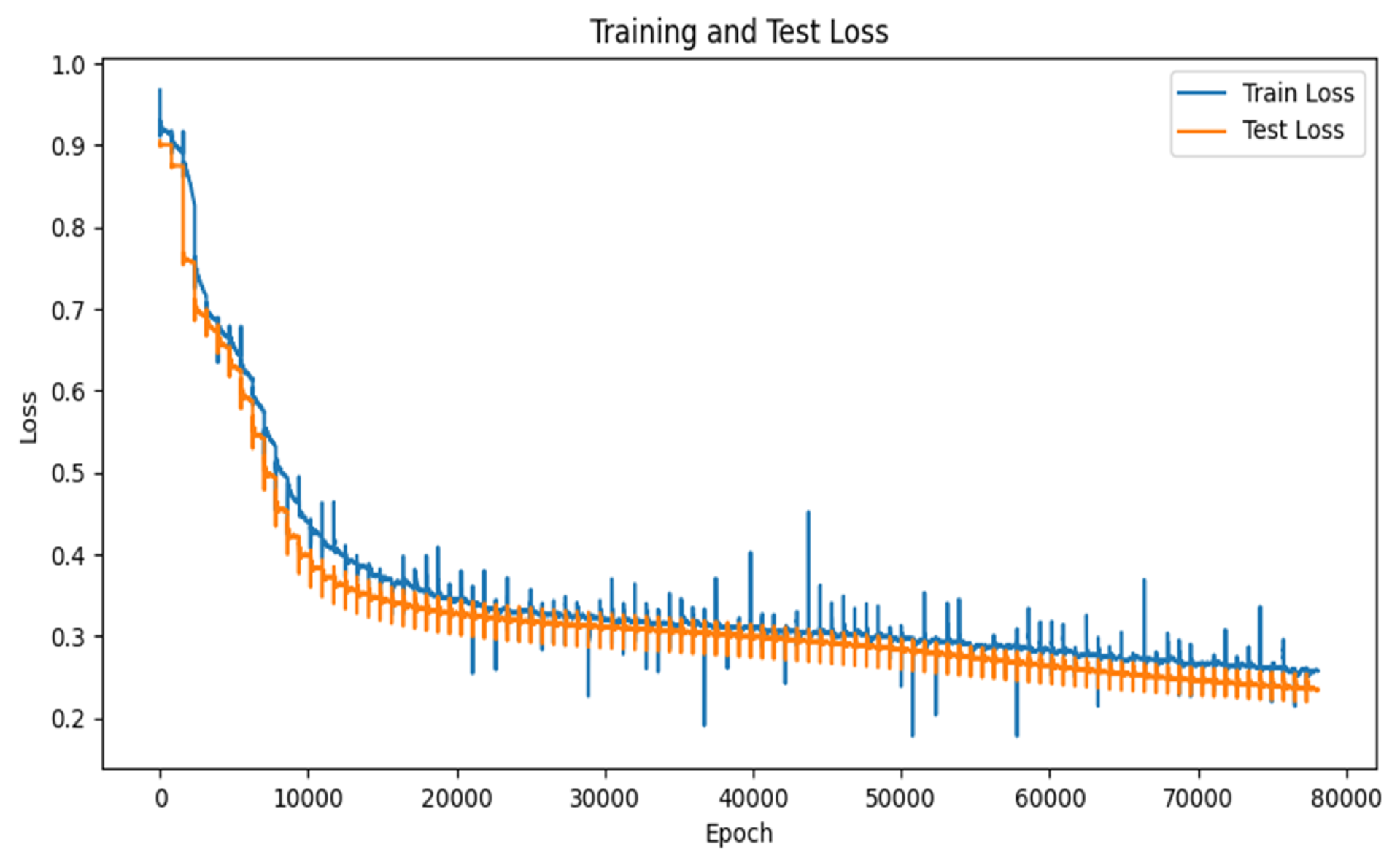
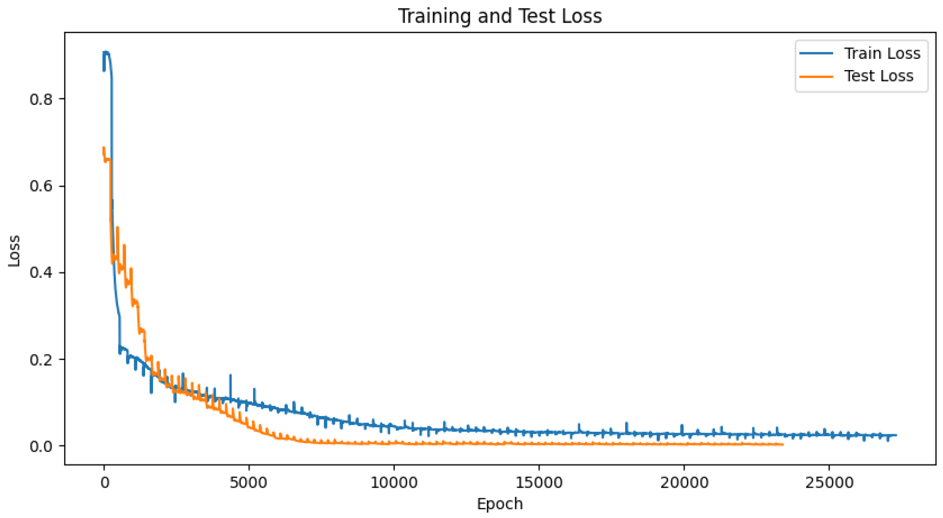
Figure 5,
Figure 6 and
Figure 7 show the loss curves of training and prediction for the three data types in the LSTM neural network. In all figures, the blue lines represent training losses and the yellow ones represent test losses, with the loss value calculated using MSE. Specifically,
Figure 5 displays the loss curve for the sub-channel signal-to-noise ratio, which converged to around 0.25.
Figure 6 shows the loss curve for the Doppler shift, converging to around 0.2. Finally,
Figure 7 presents the loss curve for delay, which converged to around 0.08.
At the same time, NMSE (Normalized Mean Square Error) is adopted to calculate the deviation between the predicted values and the true values of the predicted sub-channel signal-to-noise ratio, Doppler offset and delay. Among them, the NMSE of the signal-to-noise ratio of the sub-channel is −16.0380 dB, the NMSE of the Doppler offset is −18.1265 dB, and the NMSE of the delay is −17.8760 dB.
5.2. Adaptive Frame Structure Adjustment Performance
Then, by using the neural network trained in
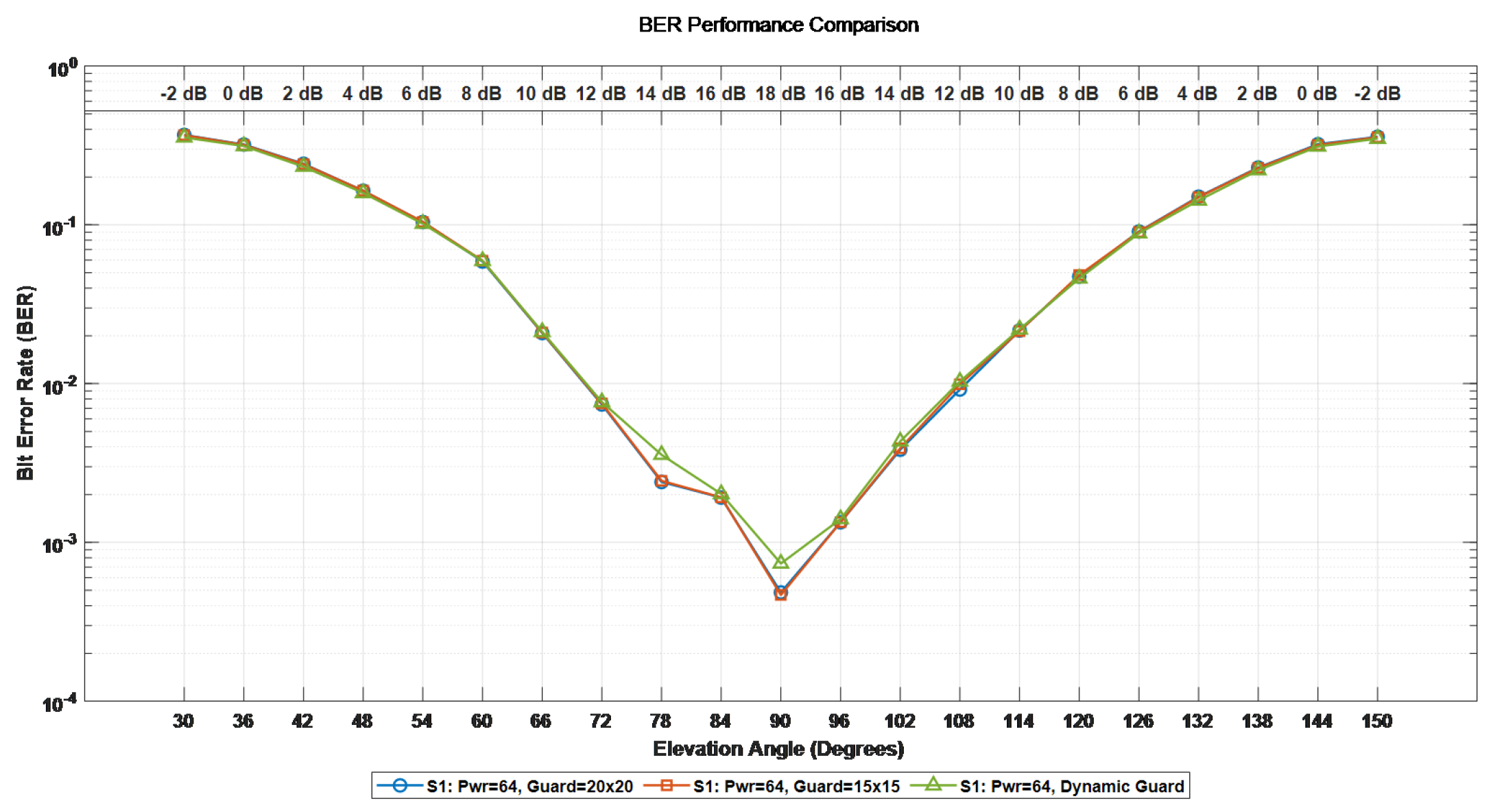
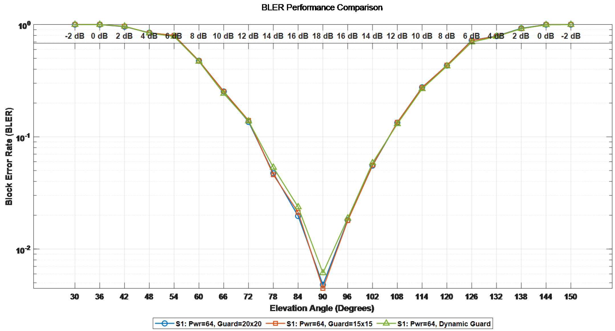
Section 5.1 and the predicted values of the sub-channel signal-to-noise ratio, Doppler offset and delay, the performance of the proposed adaptive frame configuration adjustment scheme in the OTFS system in the satellite communication scenario is demonstrated. We have configured M = 288 subcarriers, N = 14 symbol numbers, the satellite orbit altitude is 600 km, and the speed of the high-speed moving object is 10 Mach. First, an adaptive symbol loading simulation verification was conducted. We respectively set up three pilot protection band configurations, namely [20 × 20], [15 × 15], and the adaptive pilot protection band setting. The differences in system BER, BLER, and spectral efficiency under the three Settings were compared. Since the gain of the side path in satellite channels is usually very small, in this paper, when conducting threshold detection, the threshold is set to 0.05. Ensure that all valid paths in the channel can be detected and the interference of noise can be filtered out at the same time. The corresponding relationship between the elevation Angle and the signal-to-noise ratio in adaptive protection band modulation is shown in
Table 2.
In
Figure 8,
Figure 9 and
Figure 10, the green lines represent the adaptive pilot protection band configuration, the blue lines represent the pilot protection band configuration of [20 × 20], and the yellow lines represent the pilot protection band configuration of [15 × 15]. The BER, BLER and spectral efficiency of the entire system when the satellite passes over the top and moves towards the ultra-high-speed moving body were simulated. The simulation results show that since the LSTM neural network predicts the channel state information at time
t + 1 based on the channel state information at the previous time
t, the Doppler offset size and delay size of the channel at time
t + 1 can be obtained. Thus, the pilot protection band settings can be adjusted in advance, increasing the overall spectral efficiency of the system by 10.5%.
The corresponding relationship between the elevation Angle and the signal-to-noise ratio in adaptive power distribution is shown in
Table 3.
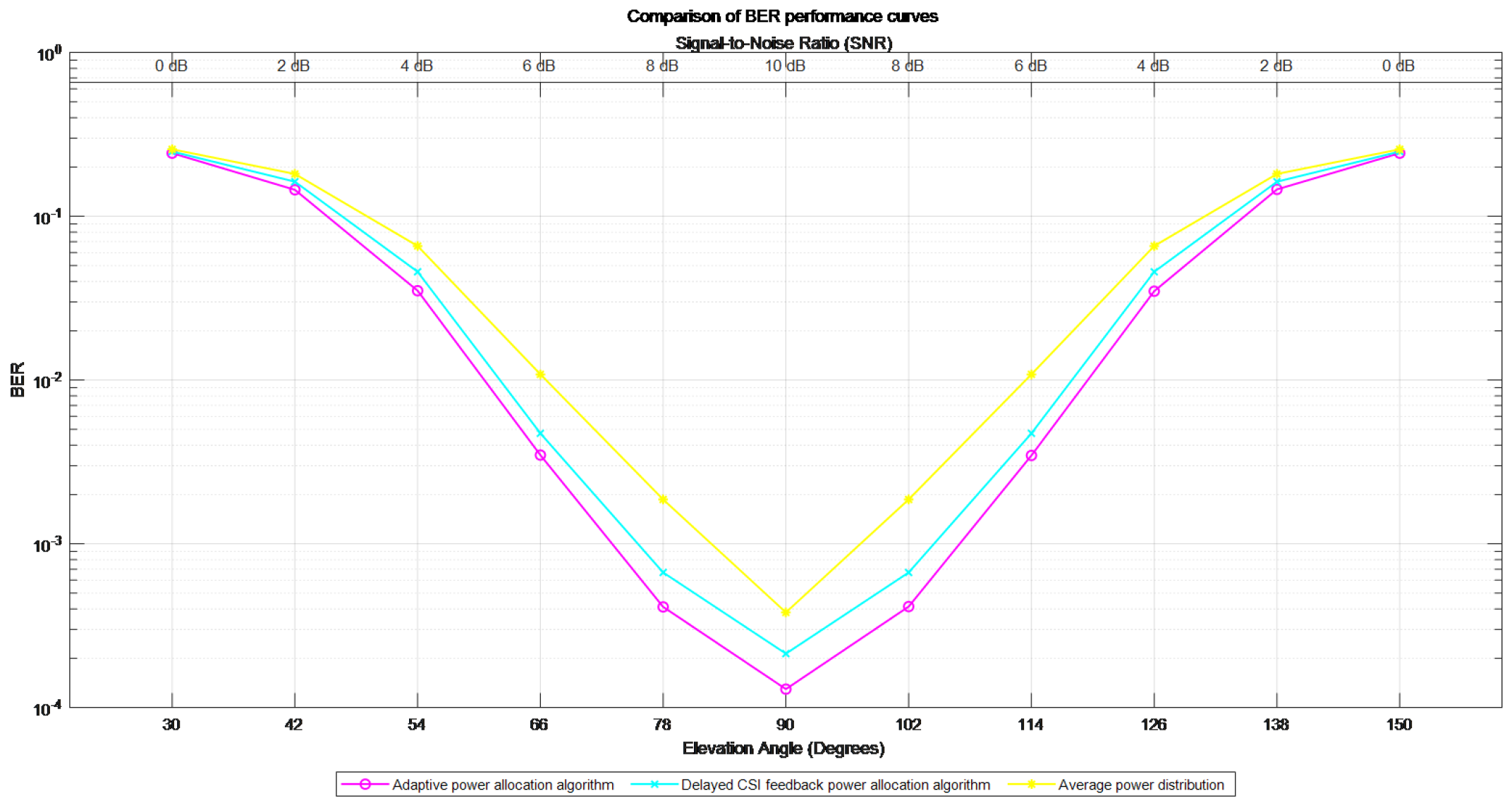
Figure 11 shows the impact of different power allocation strategies on the system BER. The red line represents the adaptive power allocation algorithm, the blue line indicates the power allocation algorithm based on delayed CSI information, and the yellow line indicates no power allocation. The simulation shows that when the satellite is overhead and moves towards the ultra-high-speed moving body, the demodulation threshold of the proposed adaptive power allocation algorithm with BER =
is 5.3 dB, and the demodulation threshold of the power allocation algorithm based on the delayed CSI information at BER =
is 5.7 dB. When uniform power distribution is performed on each sub-channel, the demodulation threshold at BER =
is 6.8 dB. Compared with the other two methods, the proposed adaptive power allocation algorithm reduces the demodulation threshold by 0.4 dB and 1.5 dB, respectively.
Figure 12 shows the impact of different power allocation strategies on the system BLER. The blue line in the figure represents the proposed adaptive power allocation algorithm, the green line represents the delayed CSI feedback power allocation algorithm, and the yellow line represents the average power allocation algorithm. The demodulation thresholds reaching BLER =
are 7.7 dB, 7.9 dB and 8.3 dB respectively. The proposed adaptive power allocation algorithm reduces the demodulation threshold of BLER =
by 0.2 dB and 0.6 dB, respectively.
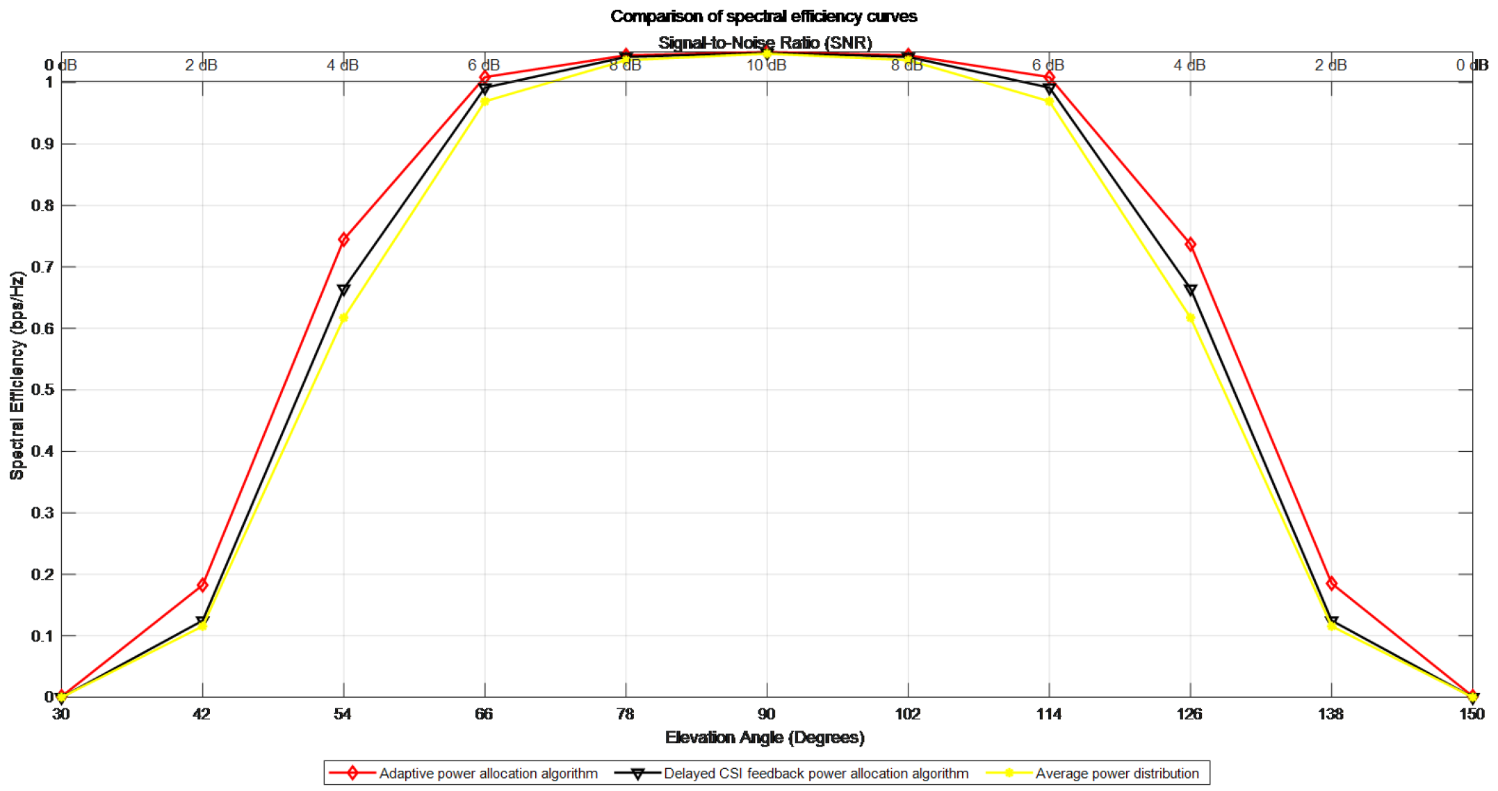
Figure 13 shows the influence of different power allocation methods on the spectral efficiency of the system. The red line represents the proposed adaptive power allocation algorithm, the black line represents the delayed CSI feedback power allocation algorithm, and the yellow line represents the average power allocation. With the development of time t, the spectral efficiency of the adaptive power allocation algorithm proposed in this paper has been significantly improved compared with that of the delayed CSI feedback power allocation algorithm and the average power allocation algorithm. During the satellite overhead period, the spectral efficiencies of the three allocation methods are the same.
5.3. Computational Complexity Analysis
In this section, we analyze the computational complexity of the entire proposed adaptive framework, including the channel prediction network, the adaptive guard band calculation, and the power allocation algorithm, to evaluate its feasibility for real-time, on-board satellite systems. The total complexity is dominated by the LSTM-based channel prediction network. The model, configured with an input size of 1, a hidden size of 32, and 3 layers, comprises a total of 21,025 trainable parameters. For a single forward pass with a sequence length of 9, the network requires approximately 371 KFLOPs (Kilo Floating-point Operations).
The subsequent adaptive resource allocation algorithms exhibit significantly lower complexity. The adaptive guard band algorithm calculates the required guard resources based on the predicted channel spread. This process involves a series of scalar subtractions, divisions, and comparisons, amounting to a negligible computational load of only a few dozen FLOPs. The adaptive power allocation algorithm, which implements a channel inversion strategy for S = 294 sub-blocks, requires approximately 9.4 KFLOPs.
Consequently, the total computational complexity of the entire adaptive framework (prediction, guard band setting, and power allocation) is approximately 380.4 KFLOPs per OTFS frame. Considering a typical frame duration of 1 to 10 milliseconds, the required processing power is estimated to be between 38.0 and 380.4 MFLOPs. This computational load, along with the model’s modest storage footprint, is well within the capabilities of modern space-grade FPGAs and AI accelerators. Therefore, we conclude that the proposed adaptive scheme is computationally efficient and holds significant potential for practical deployment in resource-constrained satellite communication payloads.
6. Conclusions
In this paper, we addressed the critical challenge of enhancing the performance of OTFS systems in high-mobility LEO satellite communication scenarios. We identified that the effectiveness of conventional resource allocation schemes is severely hampered by the lack of accurate, predictive Channel State Information (CSI), leading to suboptimal spectral efficiency and reliability. To overcome these limitations, we proposed a novel two-stage adaptive framework.
The first stage of our framework consists of a robust, multi-domain channel prediction model based on a Long Short-Term Memory (LSTM) network. By constructing a joint feature space of SNR, delay spread, and Doppler shift, our model effectively learns the complex temporal correlations of the fast-varying satellite channel and provides accurate predictions of the future CSI. The second stage utilizes this predictive CSI to perform adaptive frame configuration. This stage comprises two key innovations: a dynamic guard band adjustment mechanism that maximizes spectral efficiency by tailoring pilot overhead to the specific channel conditions, and a novel channel-inversion power allocation strategy. We demonstrated that this power allocation scheme, which strengthens weaker sub-channels to equalize the received SNR, is better suited for the unique characteristics of OTFS and results in superior Bit Error Rate (BER) performance compared to traditional water-filling approaches.
Simulation results validated the efficacy of our proposed framework. The LSTM model demonstrated high prediction accuracy, and the adaptive schemes for guard band design and power allocation yielded significant gains in both spectral efficiency and BER performance over conventional, non-adaptive methods. This work underscores the pivotal role of predictive CSI and tailored resource allocation in unlocking the full potential of OTFS for future high-mobility satellite communications. Future research could extend this framework to multi-user scenarios or explore the implementation of more lightweight neural network architectures for on-board satellite processing.


