1. Introduction
Due to the rapid advancement of intelligent automation and human–robot collaboration technologies, dual-arm robotic systems have found increasing applications in domains requiring complex operations and high adaptability, such as precision assembly, remote manipulation, healthcare, and disaster rescue. Compared to conventional single-arm robots, dual-arm systems emulate the natural coordination of human bimanual activities, enabling operations that necessitate synchronized motion—such as bilateral grasping, object rotation, or cooperative assembly. This capability substantially expands the functional envelope of robotic automation. Nonetheless, achieving synchronized and coordinated control in dual-arm robotic systems remains a formidable challenge. It necessitates real-time trajectory synchronization, directional control, spatial alignment, and accurate interpretation of operator intent to ensure coherent and stable dual-arm interactions. Existing approaches predominantly rely on wearable technologies (e.g., data gloves [
1] or inertial sensors [
2]) to capture user motion. Although it is effective in tracking hand gestures, such systems often compromise user comfort and restrict natural movement.
To overcome the limitations associated with wearable-based motion capture systems, this study proposes a non-contact, vision-based human–robot interaction framework for dual-arm control. By leveraging depth cameras in conjunction with the MediaPipe framework [
3,
4], the system obtains real-time three-dimensional positional and orientation data of the operator’s hands. This data is translated into the robot’s operational space through coordinate transformation and kinematic modeling, with inverse kinematics subsequently employed to compute the joint angles required for precise and synchronous dual-arm imitation control. The proposed framework emphasizes high precision and operational flexibility, making it suitable for applications such as teleoperation, cooperative object transportation, and interactive dual-arm manipulation tasks. This vision-based approach enhances system intelligence, naturalness, and usability by eliminating the physical constraints of wearable devices.
As robotic systems evolve from single-task automation to multi-task and collaborative functionalities, the limitations of traditional single-arm configurations become increasingly evident. Although single-arm robots are valued for their mechanical simplicity, low power consumption, and ease of integration, they are inherently constrained in performing tasks requiring spatial versatility and complex coordination. For instance, Peta et al. [
5] conducted a comparative analysis of single- and dual-arm robotic systems in electronic assembly workflows, revealing that dual-arm systems achieved a 20% reduction in task completion time by executing operations in parallel—unlike single-arm systems, which must complete actions sequentially. While dual-arm robots entail higher initial costs, their superior adaptability and long-term operational efficiency justify the investment. In particular, tasks involving dual-point interaction—such as lifting large objects, opening containers, or using tools in both hands—pose significant challenges for single-arm systems. Motoda et al. [
6] emphasized that such tasks often require additional mechanical complexity or repeated repositioning when performed by single-arm robots, thereby increasing control difficulty and the likelihood of execution failure. In contrast, dual-arm robotic systems are inherently equipped to perform synchronized bimanual tasks, closely replicating human manipulation strategies and achieving higher degrees of precision, fluidity, and coordination. These comparative findings highlight a clear trajectory: while single-arm robots remain effective for simple, repetitive tasks, dual-arm systems are becoming indispensable in scenarios that demand concurrent actions, dynamic force coordination, and interactive collaboration. As such, the shift from single- to dual-arm control represents a pivotal step in advancing human–robot collaboration. Addressing this technological transition, the present study develops a control strategy that eschews wearable devices in favor of vision-based hand tracking. Prior works, such as Wu et al. [
7], employed wearable gloves with haptic feedback; however, these solutions are frequently criticized for discomfort, reduced accuracy due to anatomical variability, and operator fatigue during extended use. Even low-latency, open-structured gloves cannot fully eliminate the drawbacks of physical contact, which continues to impair operator freedom and interaction fluidity. By contrast, the proposed non-contact vision-based hand tracking system significantly improves usability and comfort, making it a compelling alternative for high-precision dual-arm robotic control in complex and dynamic environments.
In this study, we employ contactless skeletal image tracking for capturing human posture. Two dominant methodologies for pose estimation exist: top-down and bottom-up. Top-down approaches first localize the human body and then extract keypoints within the region, while bottom-up methods detect all keypoints before grouping them into individuals. According to comparative analyses [
8,
9], MediaPipe—a top-down model—demonstrates advantages in computational efficiency and real-time tracking, particularly during continuous motion. Sarah Mroz et al. [
9] conducted a comprehensive performance evaluation between MediaPipe and the bottom-up OpenPose framework [
10,
11,
12], concluding that MediaPipe is more suitable for real-time applications due to its lightweight design and reduced computational load. Although the OpenPose exhibits higher static accuracy, its frame-by-frame processing demands limit its applicability in dynamic settings. Despite these advances, most existing dual-arm teleoperation frameworks rely on contact- or marker-based tracking, which constrains movement naturalness and user intuitiveness. Furthermore, many proposed systems are validated only in simulation, lacking real-world hardware implementation and verification. Given the increasing demand for robotic solutions in hazardous or intricate environments, enabling intuitive, remote control of dual-arm robots represents a significant step forward. This study proposes a teleoperation control strategy that enables synchronous control of two six-degree-of-freedom robotic manipulators via contactless hand tracking. The system incorporates an Intel RealSense D435 depth camera [
13] to capture three-dimensional positional and depth information of the operator’s hands, with each arm corresponding to the operator’s respective hand. To emulate real-world industrial tasks, we further examine the coordination of multiple robotic manipulators operating in parallel. The methodology addresses two primary challenges. First, the system must accurately track the operator’s hand pose and convert palm spatial coordinates into the robot’s reference frame using vision-based mapping and proportional scaling. This requires robust skeletal tracking and precise spatial transformation. Other vision-based gesture recognition approaches such as the work in [
14] employ OpenCV-based handcrafted image processing techniques (e.g., color thresholding and contour extraction) that are often sensitive to illumination variations and only provide coarse two-dimensional information, or additionally the work of Marić et al. [
15] utilizes RGB-D palm tracking but remains limited in robustness and generalizability. However, our proposed strategy leverages a common depth camera in conjunction with a skeletal feature extraction technique where this design obviates the need for specialized or contact-based sensors while enabling the acquisition of accurate three-dimensional positional and orientational data of the operator’s hands. Accordingly, a notable advantage of this work lies in its enhanced robustness to environmental variations and its flexibility to accommodate different depth cameras as well as diverse robotic manipulator platforms, thereby improving system scalability and applicability in practical scenarios. Second, motion mapping must translate the captured hand data into joint-space parameters via inverse kinematics, followed by forward kinematics to derive the end-effector trajectories. Dealing with these challenges enables real-time, non-contact, and synchronized dual-arm robot control that replicates human bimanual manipulation with high precision, adaptability, and stability.
2. MediaPipe Hand Gesture Detection
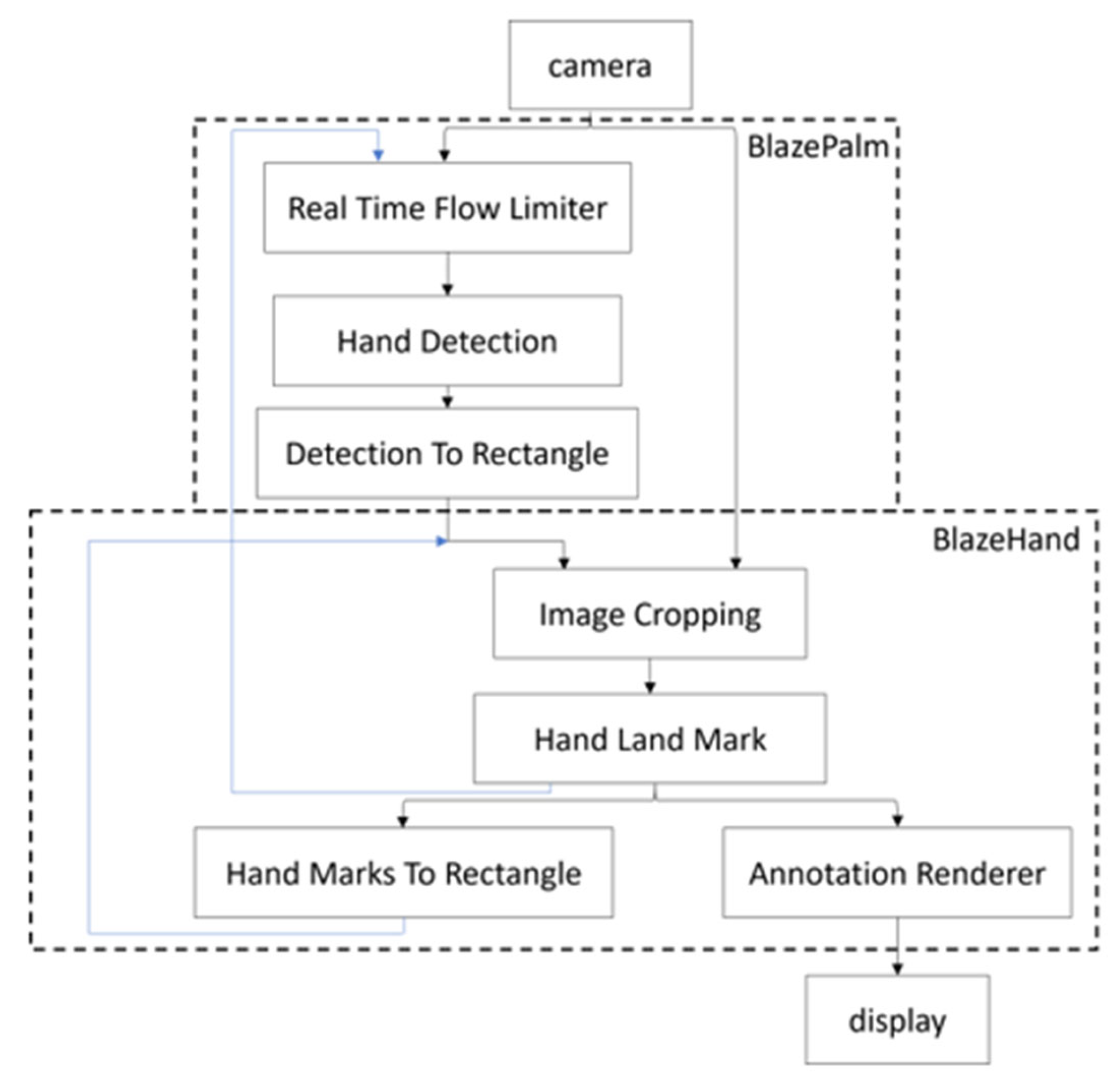
Teleoperation employs the operator’s hands as tracking targets. To accurately capture hand gestures, skeletal recognition technology is essential. Given the variety of skeletal recognition methods, each with distinct approaches extracts skeletal feature points. This work evaluates and selects the MediaPipe skeletal feature recognition framework for its validation. The MediaPipe hand gesture detection framework, as depicted in
Figure 1, consists of two model architectures: BlazePalm and BlazeHand [
16]. The BlazePalm model, indicated by the dashed line in the figure, is responsible for detecting and localizing the hand. It performs initial detection on the first frame at the Real-Time Flow Limiter stage, with subsequent hand detection inferred from the previous frame’s data, thereby eliminating the need for detection in every frame and significantly enhancing computational efficiency. The Detection to Rectangle module generates a rectangular bounding box around the detected hand based on its position. The BlazeHand model extracts hand feature points, with the Image Cropping module isolating the hand image using the rectangular bounding box. The Hand Landmark module then predicts 21 key points of the hand from the cropped image and overlays these feature points onto the hand within the image. To ensure robustness, the model evaluates the alignment confidence between the hand and its feature points. Should the confidence fall below a threshold, the system reverts to the BlazePalm model for re-detection. By integrating these two models, the framework achieves comprehensive and real-time output of 21 hand feature points.
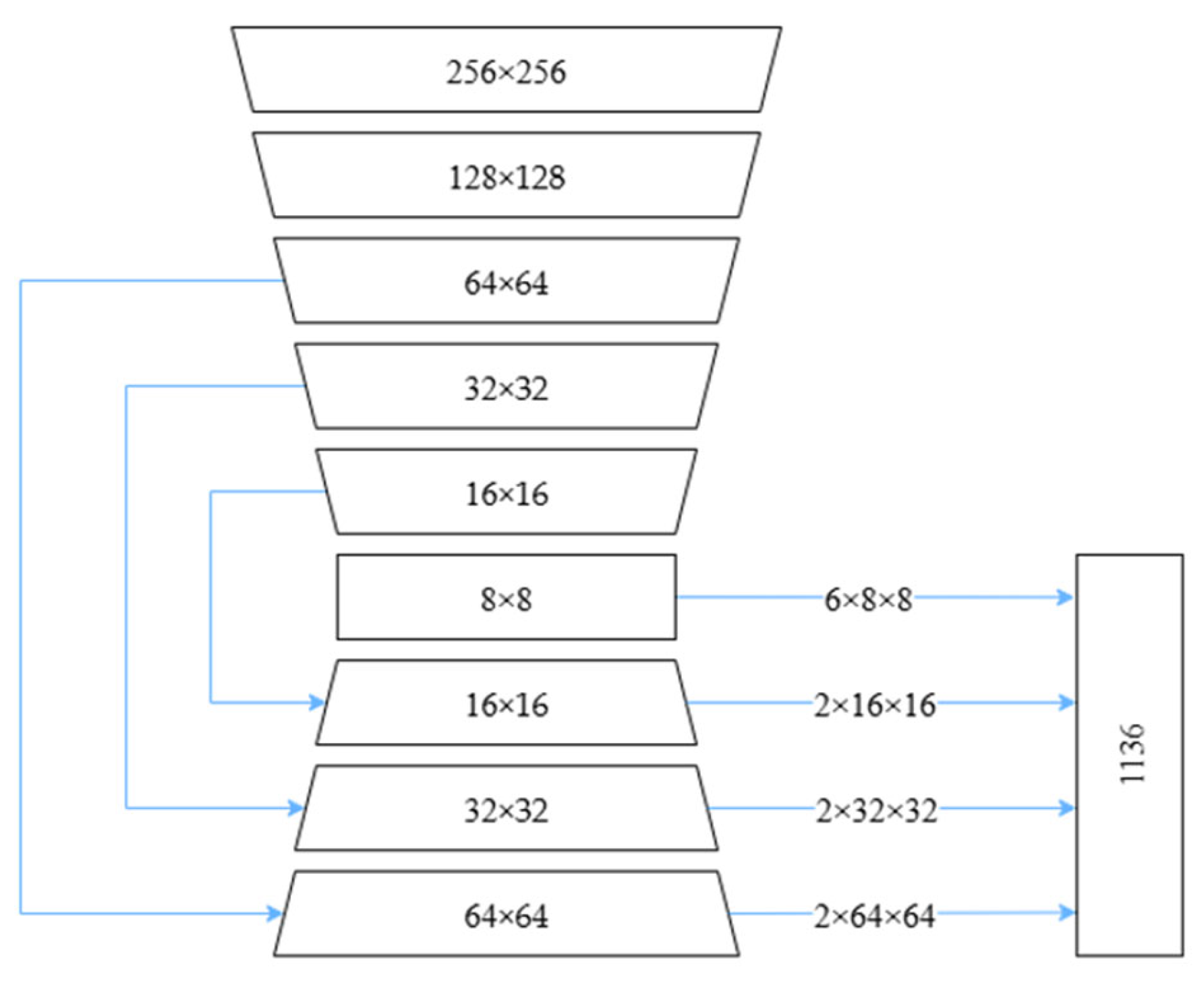
The BlazePalm detector is developed by modifying the BlazeFace [
17,
18] detector, incorporating three additional convolutional layers corresponding to feature maps of sizes 16 × 16, 32 × 32, and 64 × 64. These layers utilize residual connections to mitigate data loss and gradient vanishing issues. The overall architecture is illustrated in
Figure 2. As this detector is specifically designed for palm detection, it can be more accurately defined the bounding box for the palm compared to detecting the entire hand.
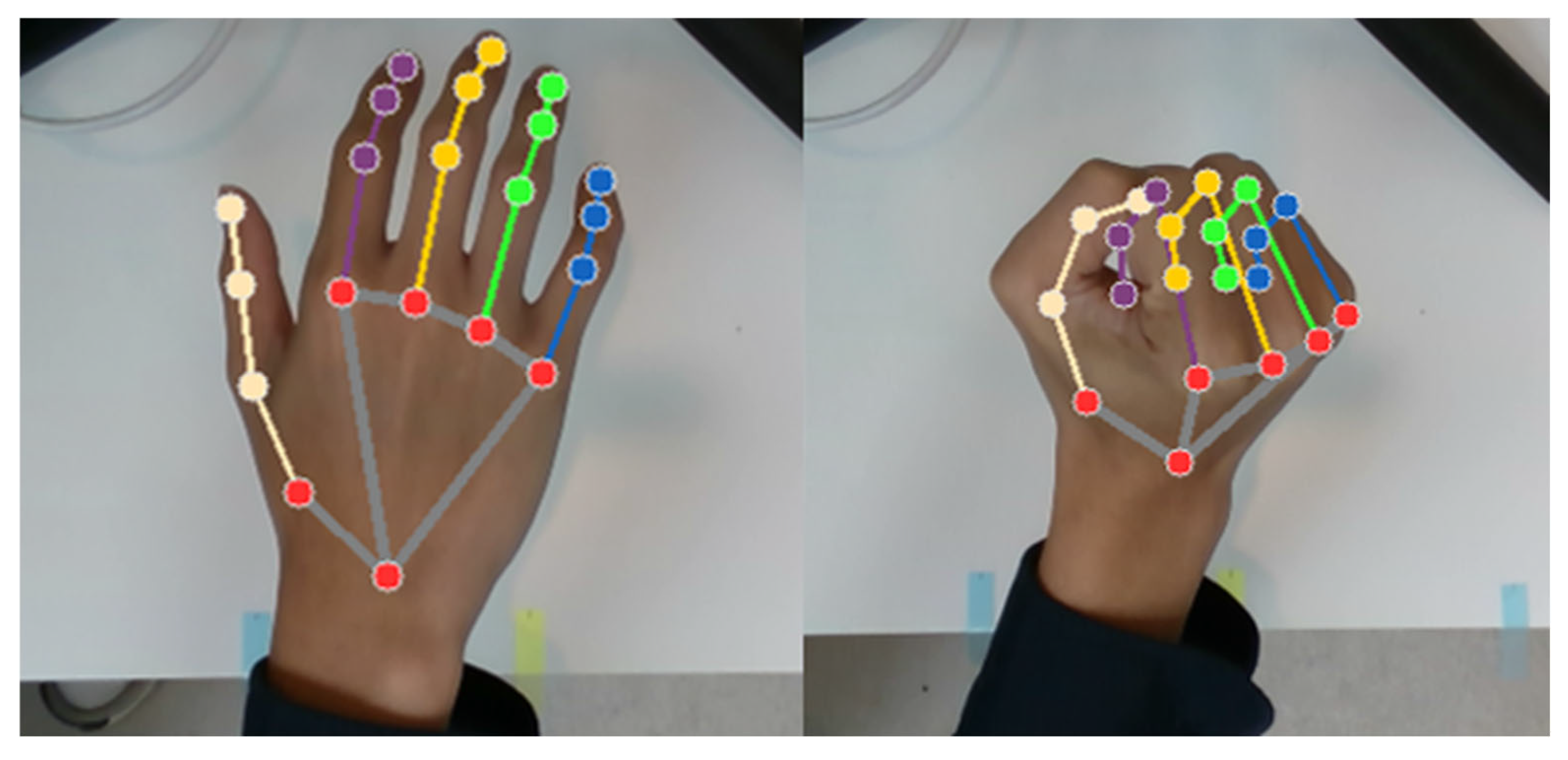
The BlazeHand model, following palm detection, precisely identifies 21 hand landmark points within the palm region of the image, as illustrated in
Figure 3. This model maintains robust stability even in cases of partially visible or occluded palms. It produces three outputs: the coordinate positions of the 21 hand landmark points, an indication of whether a palm is detected as shown in
Figure 4, and information distinguishing between the left and right hands. Control of the left and right hand grippers is based on the center point between palm points 1 and 5, which corresponds to the position of the robotic arm’s end-effector, while the distance between points 4 and 8 determines if the gripper opens or not.
3. Kinematics of Six-Degree-of-Freedom Robotic Manipulators and Problem Statement
The kinematic equations of a robot constitute a mathematical representation that describes the relationship between the robot’s structural parameters, input joint angles, and resulting motion. Through kinematic analysis, it becomes possible to accurately predict changes in the robot’s posture under given input conditions. In addition, kinematics reveals the robot’s workspace—the region that the end-effector can reach and operate within—and facilitates a comprehensive understanding of the robot’s motion characteristics. Such mathematical modeling is essential for gaining in-depth insight into the system and for enhancing the performance of robotic motion control. In addition, it also can be used to check and validate whether the solutions solved from inverse kinematics are correct. The workspace can be formally defined as the set of all positions and orientations that the robotic manipulator’s end-effector is capable of attaining.
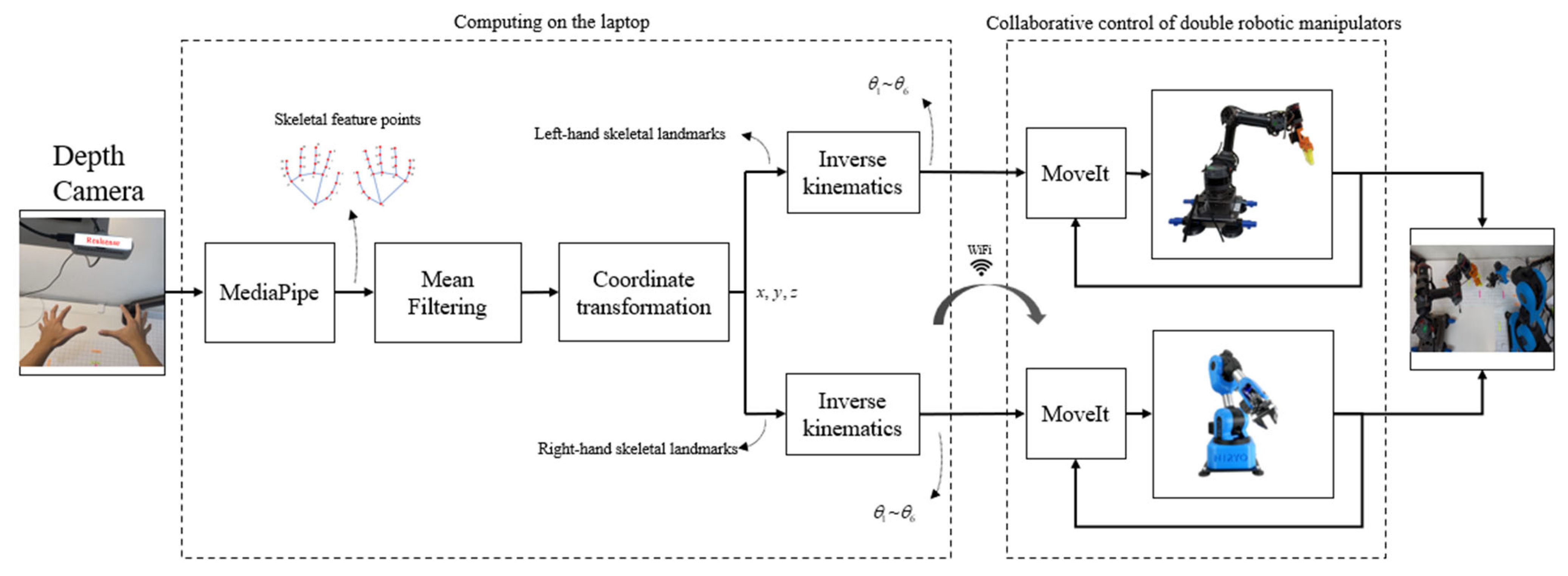
The control objective of the study is to utilize both hands for collaborative teleoperation control of double robotic manipulators based on skeletal images. A depth camera is used to capture skeletal image features of both hands and filter them. Coordinate points in the 3D space are obtained from image features via the coordinate transformation. Then, inverse kinematics is applied and control of desired angles of each joint are achieved in the closed-loop by means of the MoveIt package in the ROS. The overall control block diagram is shown in the following
Figure 5.
3.1. Forward Kinematics of Six-Degree-of-Freedom Robotic Manipulators
The homogeneous transformation matrix is a fundamental representation in forward kinematic analysis of robotic manipulators. It enables compact and efficient expression and computation of rigid body motion in three-dimensional space using matrix operations. In robotics, the spatial relationship between successive links is typically described by a series of homogeneous transformation matrices between adjacent coordinate frames. This representation facilitates the simulation and calculation of a robotic manipulator’s motion trajectory, as well as the position and orientation of its end-effector, in a more intuitive and computationally efficient manner. Prior to performing kinematic analysis, a Denavit–Hartenberg (D-H) parameter table is usually established to define the geometric relationships between joints and links. The homogeneous transformation matrix incorporates both rotational and translational motion into a unified 4 × 4 matrix structure, providing a mathematically convenient tool for handling 3D coordinate transformations. For a robotic manipulator composed of multiple revolute joints, the rotation of each joint is described by a rotation matrix, while the displacement between links is represented by a translation matrix. By sequentially multiplying these transformation matrices, one can derive the overall homogeneous transformation matrix from the base frame to the end-effector, thus fully characterizing the manipulator’s spatial configuration. In the work, double robotic manipulators are used for collaboration. One is the Niryo Ned [
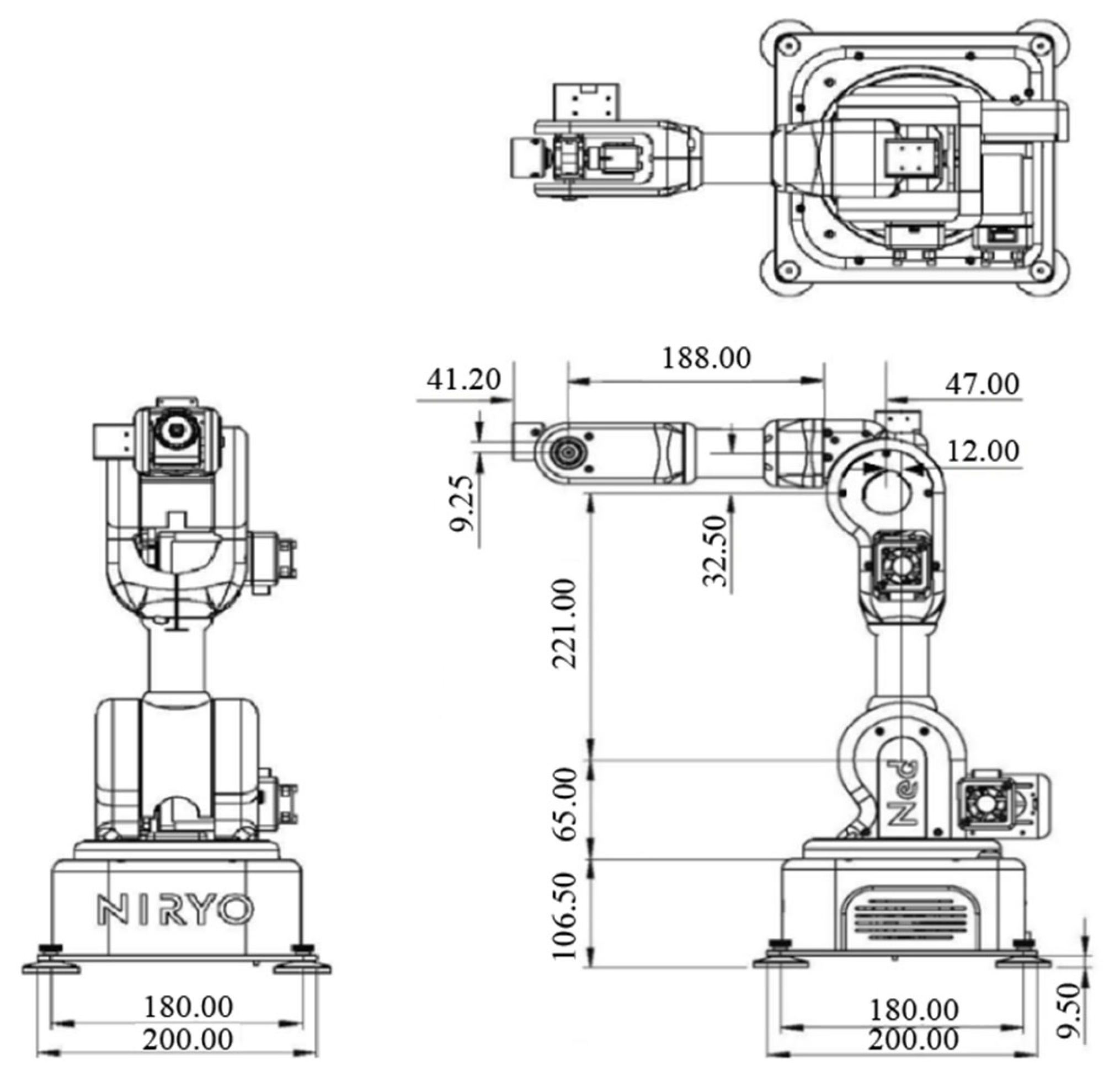
19] robotic manipulator with six-DOFs whose dimensional information is presented in
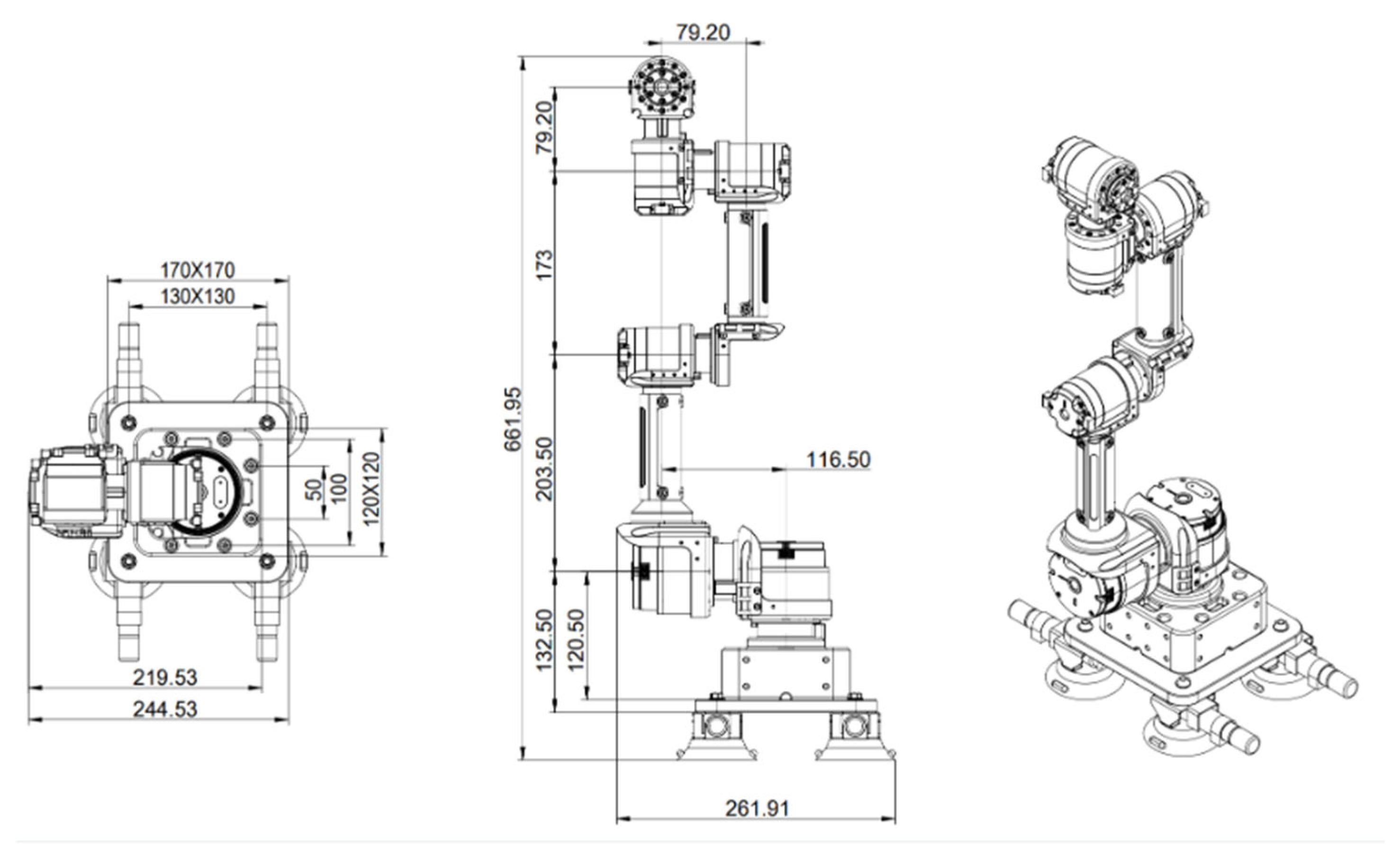
Figure 6, and the other one is Gluon [
20] six-axis robotic manipulator whose dimensional information is represented in
Figure 7.
After making sure the precise physical dimensions of the robotic manipulators, the next step is to define the coordinate frames for each axis and establish the corresponding kinematic model to enable accurate control of the robot’s motion and positioning. This model can be constructed using the D-H parameter convention, a standardized modeling method used to describe the geometric relationships between links and joints. By defining a unified set of parameters, the complex mechanical structure of the robotic manipulator can be transformed into a tractable set of mathematical expressions, thereby simplifying and systematizing subsequent kinematic and dynamic analyses. Accordingly, four primary D-H parameters are used: link length
(unit: mm), link offset
(unit: mm), link twist angle
(unit: degrees), and joint angle
(unit: degrees). These parameters describe the relative position and orientation between each joint and its adjacent link.
Figure 8 illustrates the definition of coordinate frames for each joint of the Niryo Ned robotic manipulator, from CS0 (Coordinate System 0) to CS8.
Table 1 presents the corresponding D-H parameter table for the Niryo Ned, which clearly defines and characterizes the geometric configuration and kinematic properties of the manipulator.
Based on the coordinate axes defined at each joint of the robotic manipulator, the D-H parameter table, as shown in
Table 1, can be established. From Joint 1 to Joint 6, the homogeneous transformation matrix of coordinate frame {1} relative to frame {0} is denoted as
, and the transformation of frame {2} relative to frame {1} is denoted as
. Following this pattern, the homogeneous transformation matrices of the Niryo Ned robotic manipulator can be derived and are represented by Equations (1)–(8). By successively multiplying these matrices up to the sixth joint, the complete transformation is expressed as Equation (9).
The second Gluon robotic manipulator, as illustrated in
Figure 9, has its D-H parameters listed in
Table 2. Based on the configuration, coordinate frames can be established at each joint accordingly. The corresponding homogeneous transformation matrices for the Gluon robotic manipulator, denoted as Equations (10)–(16), are derived based on these coordinate frames. By sequentially multiplying these matrices up to the sixth joint, the overall transformation can be expressed as Equation (17).
3.2. Inverse Kinematics of Six-Degree-of-Freedom Robotic Manipulators
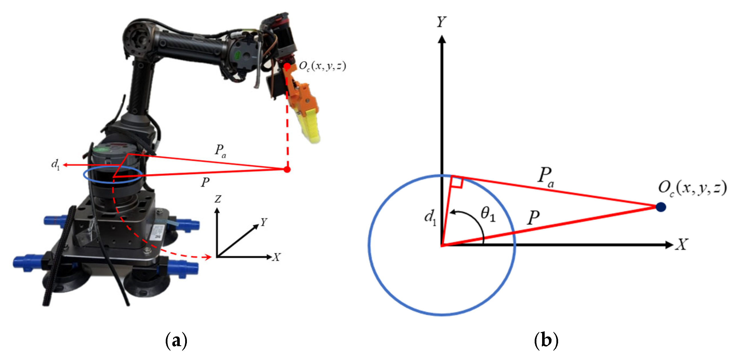
The homogeneous transformation matrix is not only a fundamental tool in forward kinematics—used to compute the position and orientation of the end-effector given specific joint angles—but also plays a critical role in solving inverse kinematics problems. The goal of inverse kinematics is to determine the set of joint angles required for the end-effector to reach a desired position and orientation. By performing algebraic operations on the homogeneous transformation matrices, the corresponding joint variables can be derived. In this study, a geometric approach is adopted to calculate the joint angles of the robotic manipulator. The geometric method is characterized by its intuitive and easily understandable nature, as it determines the reachable workspace by analyzing the structural geometry of the robot. Specifically, the first three joint angles of the manipulator are computed in order to guide the end-effector to the target position. As shown in
Figure 10, the first joint angle corresponds to the rotation about the
X-axis toward the link
of the Gluon robotic manipulator.
denotes the position of the end-effector,
represents the distance from the origin of the robotic manipulator to the end-effector, and
is the combined length of Link 2 and Link 3 of the Gluon manipulator. The first joint angle can be calculated using Equations (18)–(20).
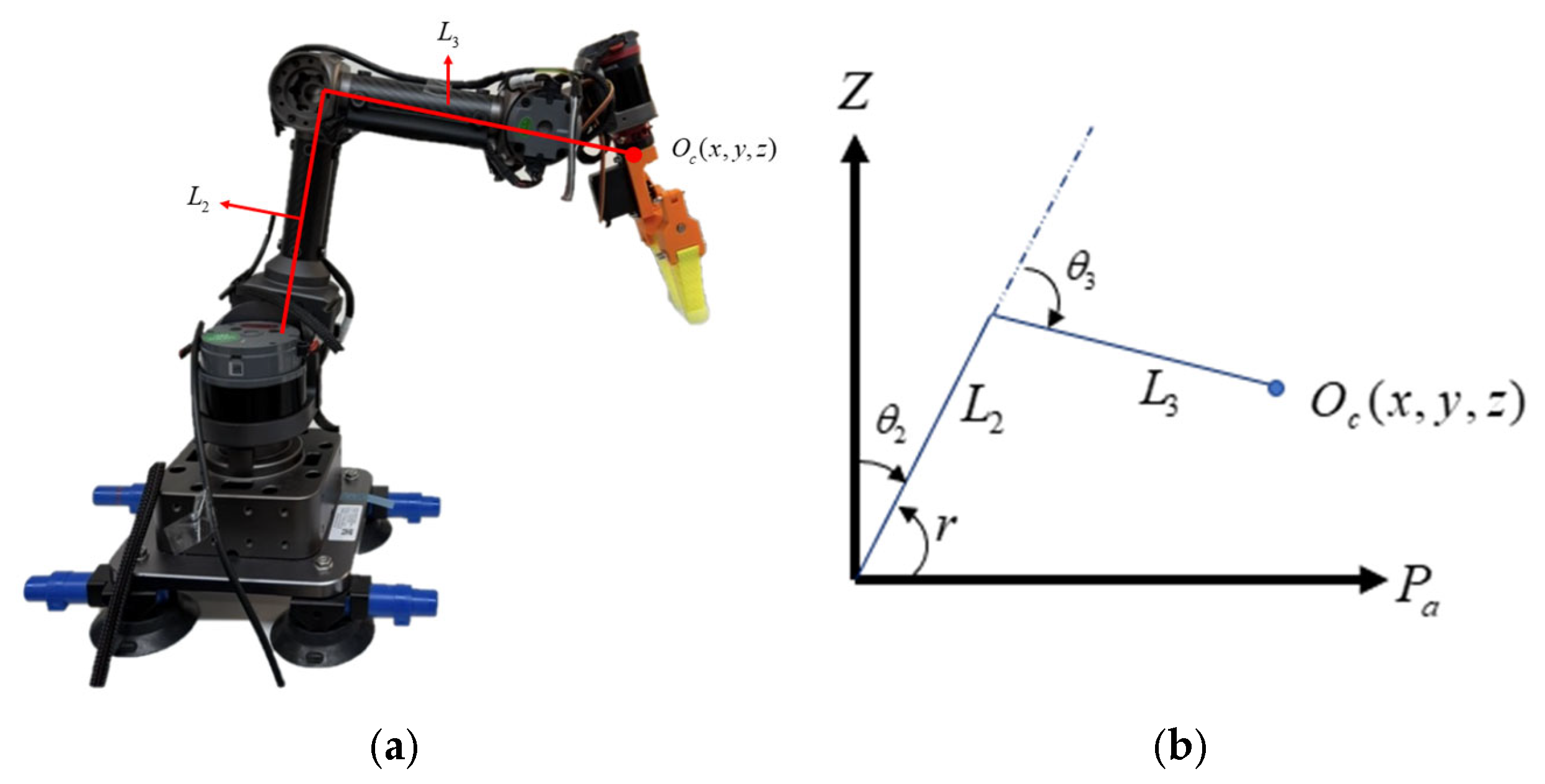
In inverse kinematics, the computation of the second joint angle
and the third joint angle
is based on the known lengths of Link 2 and Link 3. As illustrated in
Figure 11, the angle
corresponds to the rotation of the robotic manipulator about the
Z-axis toward the second joint, while
represents the angle between Link 2 and Link 3. The angle
can be determined using the law of cosines. Once
is obtained,
can be calculated through trigonometric relationships. As shown in
Figure 10, the angle
denotes the angle between Link 2 and the axis
, and it is defined by Equation (21). Using the angle
, in conjunction with
,
can then be derived via trigonometric relations.
The above expression can be represented as
, from which the following equation can be derived
After completing the inverse kinematics calculations, the joint angles of the first three axes of the robotic manipulator can be obtained. These joint angles are then substituted into the forward kinematics model to determine the position of the end-effector.
Figure 12 and
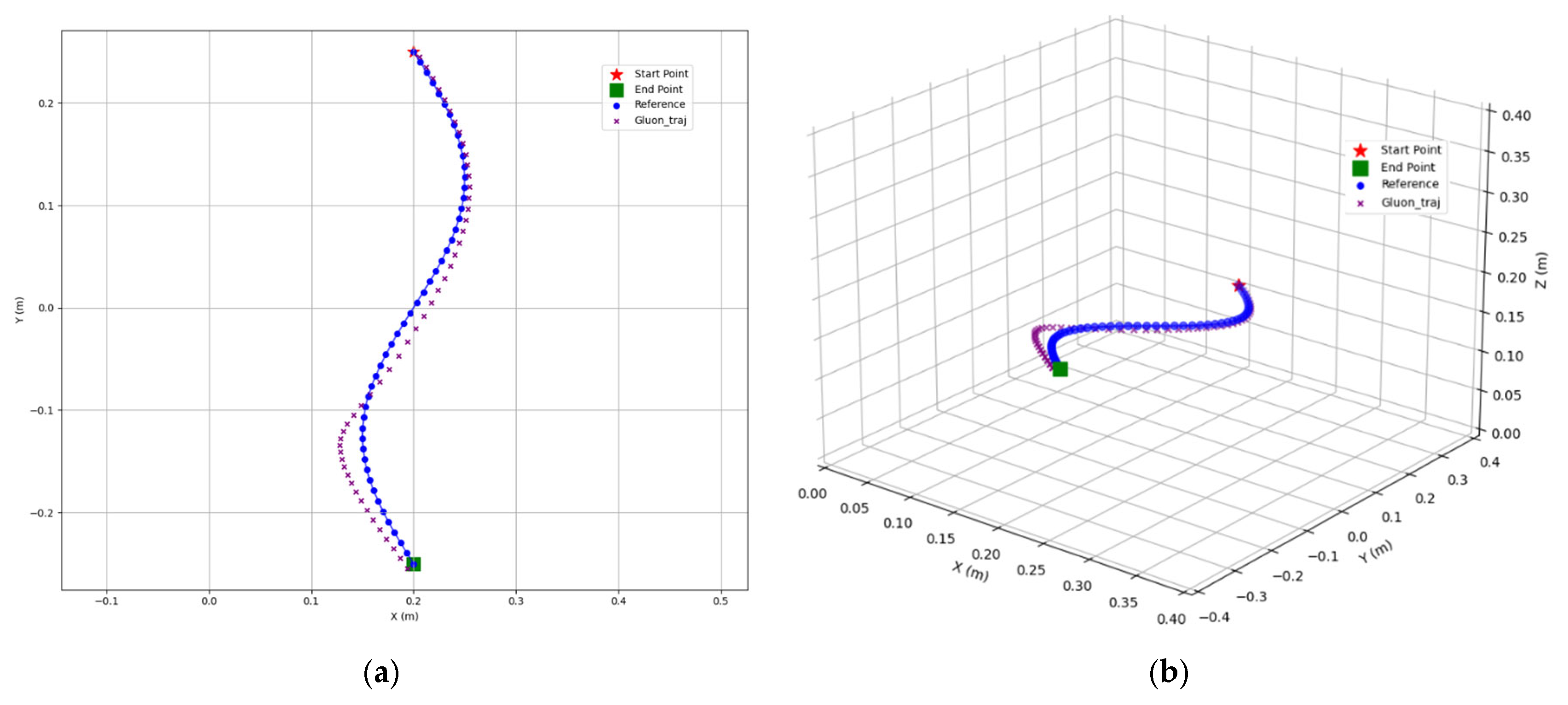
Figure 13 illustrate the position of the Gluon robotic manipulator’s end-effector obtained through this kinematic approach. Based on the computed positions, a motion trajectory is designed to guide the end-effector through space. Kinematic validation is conducted in both the 2D XY plane and the 3D XYZ space. In the 2D case, a sinusoidal trajectory, as described in Equation (26), is employed—where the
X-axis and
Y-axis values correspond to the coordinates of the motion. This trajectory is discretized into 50 points, beginning at the position (0.2, 0.25) and ending at (0.2, −0.25).
An elliptical trajectory in 3D space is formulated and analytically described through parametric equations. The ellipse is centered at the point (0.275, 0, 0.15), and its motion is defined by the following Equations (27)–(29).
In this context, serves as the trajectory parameter, used to describe position variations along the elliptical path. The ellipse has a semi-major axis length of 0.2 and a semi-minor axis length of 0.075. It lies within the XY plane and is inclined at an angle of 33.7° with respect to the positive X-axis. The coefficients and represent the unit vector components of the semi-minor axis direction along the X and Z axes, respectively. A key characteristic of this trajectory is its non-planar nature. Unlike a conventional 2D ellipse, this trajectory does not lie entirely within any of the standard Cartesian planes (i.e., XY, XZ, or YZ planes). Instead, it is distributed over an inclined plane in 3D space. This spatial configuration enables precise path control in complex environments, providing a solid mathematical foundation for subsequent motion planning and trajectory tracking. The motion begins at the starting point (0.337, 0, 0.192) while and proceeds to the top vertex (0.275, 0.2, 0.15) while and continues to the opposite side point (0.213, 0, 0.108) at , then to the bottom vertex (0.275, −0.2, 0.15) at , and finally returns to the starting point, completing the elliptical trajectory. These key position coordinates validate the accuracy of the trajectory design and serve as reference points for path verification in practical applications.
In this study, the Niryo Ned robotic manipulator and the Gluon robotic manipulator employ distinct inverse kinematics solvers. The inverse kinematics for the Niryo Ned robotic manipulator is computed using MoveIt within the Robot Operating System (ROS) [
21].
Figure 14 and
Figure 15 validate the accuracy of its inverse kinematics. After processing the transformed coordinates through inverse kinematics, the position of the end-effector is analyzed using the previously discussed forward kinematics. The validated trajectory motion aligns with the trajectory of the Gluon robotic manipulator. As observed in the figures, the kinematics of the Niryo Ned robotic manipulator is calculated with high precision, with minimal deviation between the motion trajectory and the target trajectory. Therefore, this study employs two distinct kinematic algorithms for the experimental validation.
4. Mapping from Image Coordinates to the Coordinate System of the Robotic Manipulators
We employ a linear mapping method here, which differs from the conventional camera coordinate transformation. Although the pixel value range remains consistent across different depths, the real-world scene captured by the camera varies in terms of its upper and lower bounds at different depth levels. Therefore, the proposed mapping method applies a depth-specific compensation to ensure that the transformation from the palm coordinate space to the robotic manipulator’s movement space is free from distortion. Moreover, this mapping method does not require consideration of the extrinsic parameters between the depth camera and the robotic manipulators, only the image distance of the depth camera needs to be taken into account. The study aims to enable gesture-based control of a robotic manipulator through vision input by accurately converting the pixel coordinates of the hand in the image into three-dimensional spatial coordinates recognizable and controllable by the robot. The mapping relationship is defined in Equations (42)–(45). The hand’s position in the image is represented by pixel coordinates
and a depth value
, which is provided by the depth camera. Since the robotic manipulator operates within a three-dimensional coordinate system rather than in pixel units, it is necessary to establish a transformation model that maps the “image coordinate space” to the “robot control space.” It can be obtained using a linear transformation. To begin with, the valid movement range of the left palm in the image is defined by determining the minimum and maximum values in the pixel coordinate system, as described below:
The above inequalities define the boundary of pixel coordinate positions within the left-hand region. The corresponding boundary range for the pixel coordinates within the right-hand region is defined as
where
and
represent the coordinate positions in the image space, while the symbol
denotes the depth value acquired from the depth camera. The parameters
,
and
,
signify the horizontal boundaries in the image space for the left and right hands, respectively. Similarly,
,
and
,
represent the vertical boundaries for the left and right hands, while
,
and
,
correspond to the upper and lower depth boundaries for the left and right hand regions in the image space. These boundaries in the robot’s control space can be represented as
The above inequalities define the boundary of coordinate positions in the robotic manipulator’s control space corresponding to movements within the left-hand region. Likewise, the boundaries for coordinate positions within the right-hand region of the robotic manipulator’s control space can be represented as
Let
,
and
,
denote the movable range of the robotic manipulator along the
x-axis within the control space;
,
and
,
denote the movable range along the
y-axis;
,
and
,
signify the movable range along the
z-axis within the control space. By mapping the positions of the user’s hands in the image space to the control space of the robotic manipulators, a proportional relationship between image coordinates and the robotic control space is established. This mapping enables the end-effector of the robotic manipulator to move in accordance with the operator’s hand movements. Based on this proportional relationship, the following coordinate transformation relationship can be derived as
where
represents the planar coordinate point of the left-hand region. Similarly, the coordinate transformation for the right-hand region can be represented as
where
signifies the coordinate point of the right-hand region. To enhance overall transformation accuracy and operational stability, compensation mechanisms are designed to address potential linear mapping errors along each axis. The compensation values for the left and right hands are listed in the following
Table 3, with the adjustments separately applied to each hand. The coordinates for the left hand are represented as
and
, while the compensation for the right hand’s axes is denoted as
and
. As shown in the equations above and based on the preceding derivation, the palm’s position information in the image space can be successfully mapped to the robotic manipulator’s control coordinate system using the corresponding transformation relationships.
5. Experimental Results and Discussions
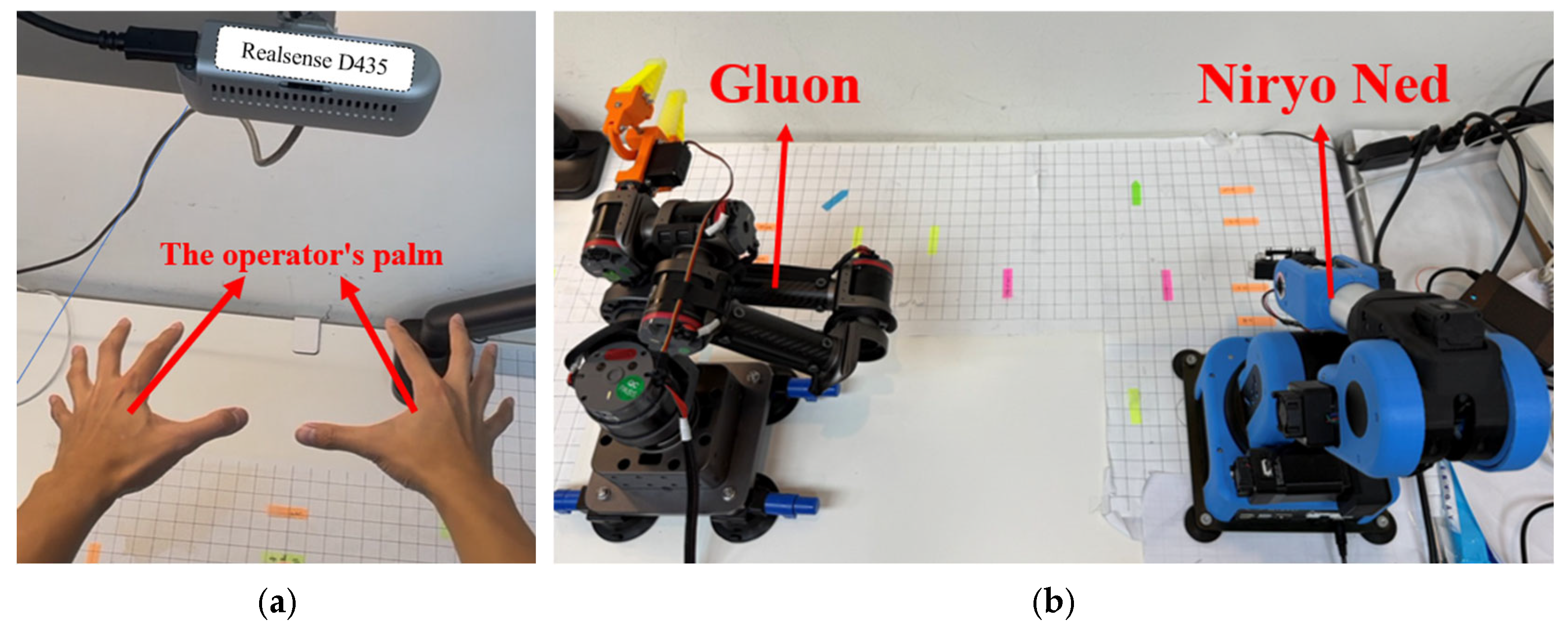
Robotic manipulators manufactured by Niryo and Mintasca are used to experimentally validate the effectiveness of the proposed teleoperation control method. The Niryo Ned robotic manipulators employs a Raspberry Pi 4 as its central control board, running an operating system based on Ubuntu 18.04 and ROS Melodic to manage motion control, sensor data processing, and communication. Its motor system comprises three NiryoSteppers stepper motors and three Dynamixel XL servo motors, supporting the EasyConnect modular end-effector system and vision kit. In contrast, the Mintasca Gluon utilizes QDD Lite-NE30 Smart Compliant Actuators (SCA) for distributed control, with each actuator integrating a brushless DC motor, high-precision encoder, reducer, and driver, eliminating the need for a single central processor. In the experimental setup, a RealSense D435 depth camera shown in
Figure 16a is employed to capture depth information. This depth data, obtained through coordinate transformations, enables operators to control double robotic manipulators shown in
Figure 16b enhancing precision and versatility in spatial manipulation tasks. The Gluon robotic manipulator represents the operator’s left hand, while the Niryo Ned robotic manipulator represents the operator’s right hand. To better mimic the movement of the operator’s palms, the distance between the origins of the double robotic manipulators is set to match the natural distance between the operator’s palms when the arms are extended forward.
Essentially, this study assesses the capability of robotic manipulators to replicate the motion trajectories of the operator’s palms and examines the applicability of the proposed method across robotic manipulators with varying configurations. In the experiment, the operator uses the depth camera from a distance to capture hand gestures. The acquired data is transmitted to a computer for coordinate transformation. The transformed information is then sent to the robotic manipulator’s end-effector to adjust its position. Simultaneously, the orientation of the robotic manipulator’s end-effector can be adjusted based on the operator’s hand orientation, enabling more precise replication of the operator’s movements. The time taken is recorded in the average duration of each step of the experiment. For each step of completing the task, the average time from capturing the image to detecting the hand pose and generating coordinate points is approximately 120.04 ms. Subsequently, mapping the coordinate points to the robotic manipulator takes about 132.06 ms. The computational time for the robotic manipulator’s kinematics is approximately 42.85 ms. Finally, sending the position command to the robotic manipulator and completing the motion takes about 1121.15 ms. The overall operation time is approximately 1416.1 ms.
The depth camera is positioned at a height of 70 cm above the desktop and is utilized to capture the operator’s hand gesture information. This information is transmitted to a laptop for computational processing, including mean filtering and coordinate transformation. The transformed positional data is then used to calculate the joint angles of the robotic manipulator through inverse kinematics. These joint angles are input into MoveIt to control the robotic manipulator, achieving remote control of double robotic manipulators. In the experimental setup, the operator is positioned 70 cm from the desktop, where a depth camera is used to capture the operator’s hand gestures. The camera’s field of view defines the operational space for the operator’s movements, which corresponds to the workspace of double robotic manipulators. The bases of the double robotic manipulators are positioned with an inter-base distance of 0.7 m at the origin. The Gluon robotic manipulator represents the operator’s left hand gestures, while the Niryo Ned robotic manipulator represents the right hand gestures. To enhance the robotic manipulators ability to mimic the operator’s movements accurately, the Gluon arm is configured in the negative y-axis plane, and the Niryo Ned arm is configured in the positive y-axis plane. This arrangement ensures both sensitivity in the workspace and precise positional accuracy.
Figure 17 shows the time-sequence snapshots of the task is presented. Initially, the operator’s left hand moves to the starting point, mimicking the action of picking up an object. The operator’s right hand remains stationary, awaiting the left hand’s movement. Once the left hand reaches the starting point, it proceeds to the midpoint between the double robotic manipulators to perform the object handover. After the operator’s right hand receives the object, it moves to the endpoint to place the object.
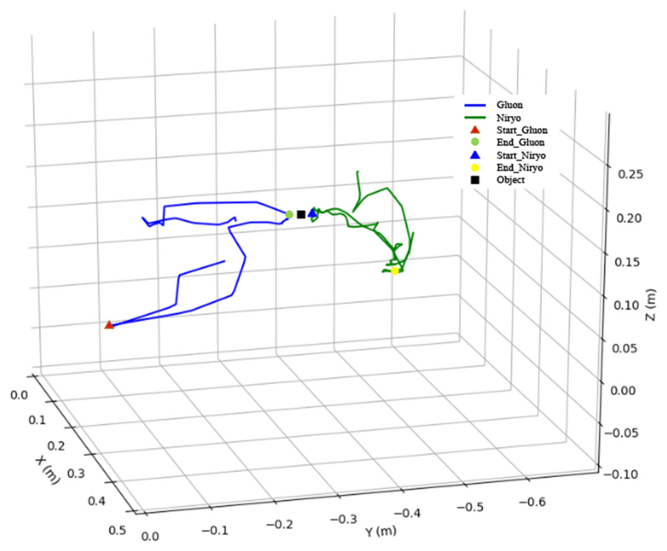
Figure 18 and
Figure 19 show the motion trajectories of the double robotic manipulators for this task. The left hand controls the Gluon robotic manipulator to execute the experimental trajectory, initially moving to the starting point to represent the grasping of an object. It then proceeds to the endpoint of the Gluon manipulator’s task, which serves as the handover point between the left and right hands, denoted by a black square. Subsequently, the right hand controls the Niryo robotic manipulator, using the handover point as its starting point and moving to the endpoint, which represents the placement of the object. As both robotic manipulators continuously record the operator’s hand gestures, even during non-active phases of the task, the starting point in
Figure 18 and
Figure 19 does not appear at the beginning of the trajectory, nor does the endpoint appear at the end. The figures reveal that, prior to filtering, the motion trajectories of both robotic manipulators exhibit noises, resulting in positional inaccuracies during the handover. However, the filtered trajectories demonstrate that both robotic manipulators can smoothly reach their designated positions throughout the process, with the acceptable errors caused by noises during the handover. Furthermore, the starting and ending positions are precisely achieved, thereby validating the effectiveness and accuracy of the proposed control scheme. Additionally, this study addresses the issue of hand tremors or minor errors in sensor data acquisition during the operator’s movements. The task trajectory is executed ten times, with an average duration of 36.5 s. The position of the palm after coordinate transformation is compared with the position of the robotic manipulator’s end-effector for the error evaluation. The coordinates of all points in each task are averaged, and the Euclidean distance is calculated simultaneously. Additionally, the Root Mean Square Errors (RMSE), mean errors, and maximum errors are investigated, as presented in
Table 4 and
Table 5. The larger average error observed in the Gluon robotic manipulator is attributed to measurement errors of each link. In contrast, the Niryo Ned robotic manipulator using the inverse kinematics of MoveIt demonstrates the higher position accuracy. However, these position errors are acceptable and the task is still successfully completed, enabling effective object handoff.
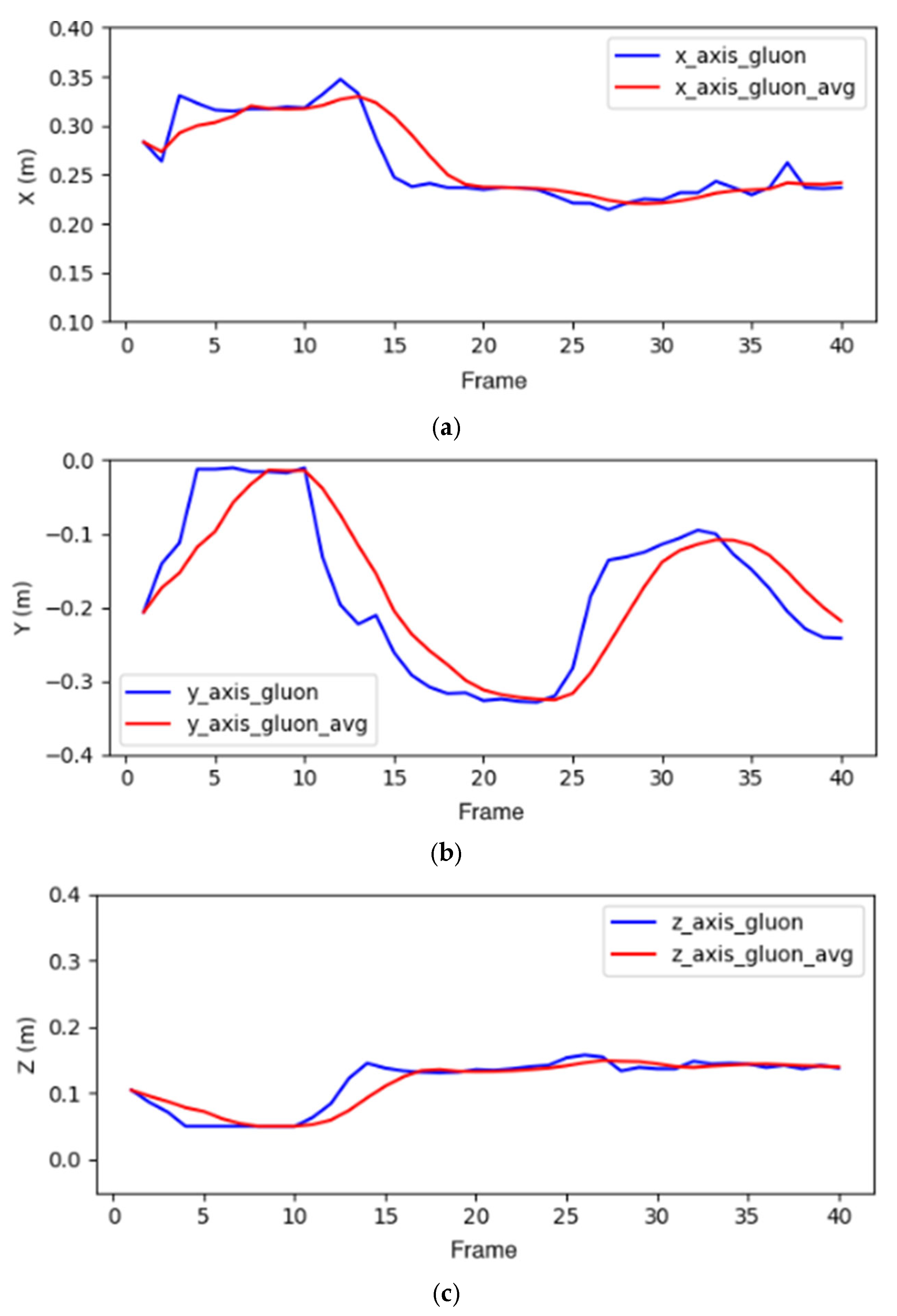
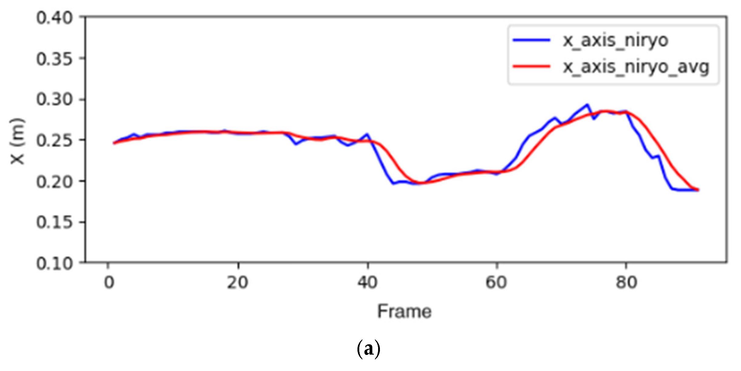
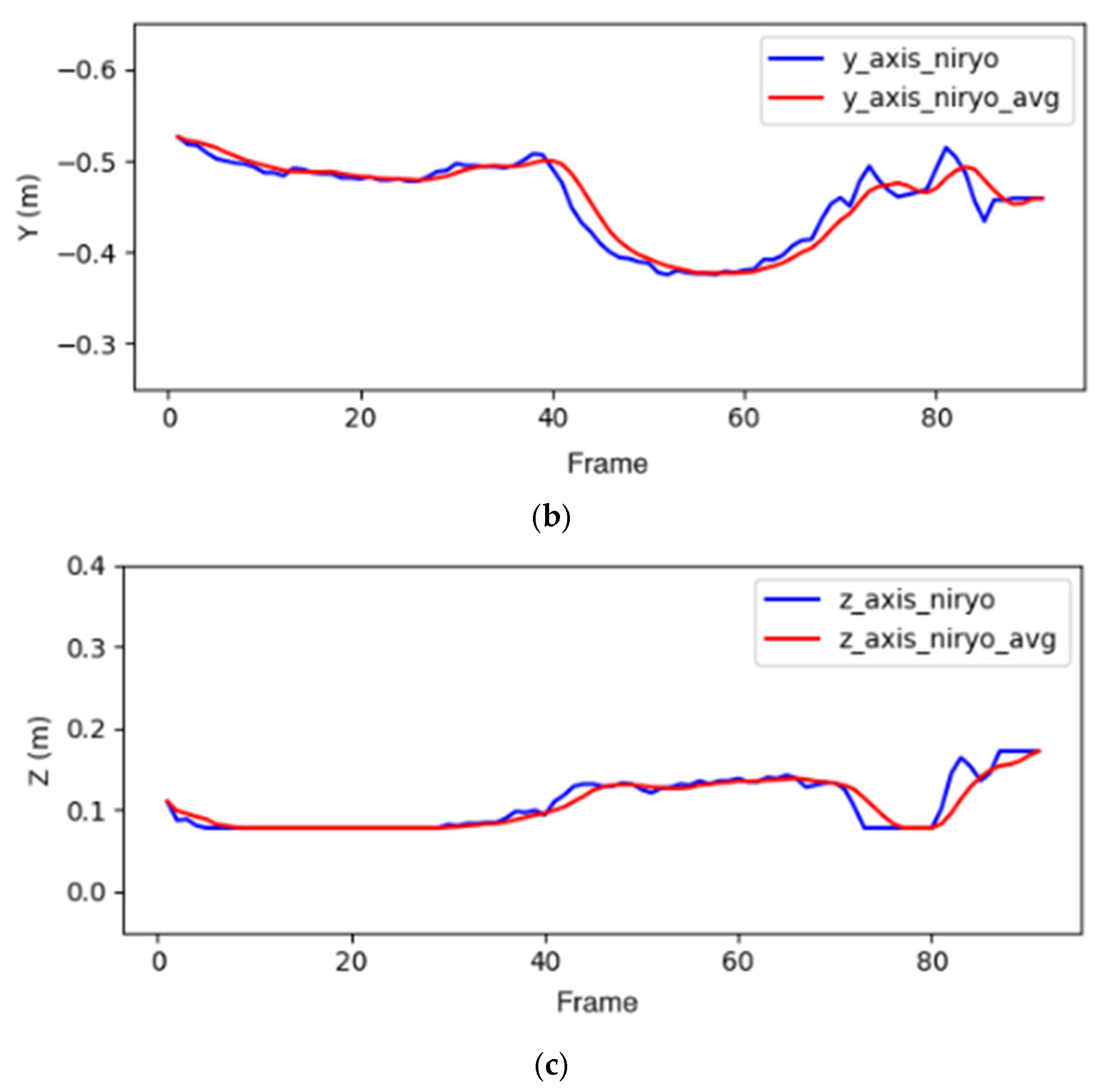
To improve the robotic manipulator’s following ability to track the operator’s palm movement speed while effectively reducing noises, a fast and efficient filter (i.e., moving average filter) is used. It can be seen in
Figure 20 that the use of a smaller window size still results in a noticeable error. Conversely, when too many values are included in the average process, the palm will move an additional position to complete the averaging, leading to a delay in the robotic manipulator’s motion. In addition, the noise distortion happened with 9 points in the filter of
Figure 20. According to the principle, the selected every five values here are averaged. The positional data (x, y, z) of the Gluon and Niryo Ned robotic manipulators’ end-effectors are, respectively, recorded in
Figure 21 and
Figure 22. We can see from these figures that mean filtering indeed can effectively remove noises to make the motion trajectory smoother. Although the filtered parameters exhibit a slight delay compared to the unfiltered data, the positional information corresponding to the operator’s movements is successfully achieved.
In summary, precise coordinate transformation and filtering are significant for the remote control of robotic manipulators. The experimental results demonstrate that, within the task trajectories, the robotic manipulators can accurately replicate the positions of the operator’s hands and complete the object transfer task. Furthermore, although the filtered positional movements exhibit a slight delay, the target positions are still successfully achieved.
