Article

Research on Soft-Switching Power Amplifier for Electromagnetic Bearings

College of Information Engineering, Nanchang Hangkong University, Nanchang 330063, China
*
Authors to whom correspondence should be addressed.
Electronics 2025, 14(19), 3858; https://doi.org/10.3390/electronics14193858
Submission received: 29 July 2025 / Revised: 20 September 2025 / Accepted: 22 September 2025 / Published: 29 September 2025

Abstract

Traditional active magnetic bearing power amplifiers usually adopt hard-switching circuit topologies with simple structures and strong practicability. However, such topologies suffer from high switching losses and easy generation of current noise. To address these issues, this paper proposes a soft-switching power amplifier topology for active magnetic bearings. By employing soft-switching technology, zero-voltage notches are generated through an auxiliary resonant circuit, enabling the switching transistor s to turn on and off at the zero-voltage notch moment, thereby reducing switching losses and improving system efficiency. The working principle of the soft-switching power amplifier topology is analyzed in detail, and the proposed scheme is verified through system simulation and experiments. Results show that the soft-switching power amplifier can effectively reduce switching losses and current noise, while its dynamic performance and operating bandwidth are comparable to those of traditional hard-switching power amplifiers. With an output current of 3 A, the efficiency of the soft-switching power amplifier can be enhanced by 10%.

1. Introduction

Active Magnetic Bearings (AMBs) offer advantages such as high rotational speed, long service life, and wearlessness [1], and are widely used in fields such as flywheel energy storage, high-speed motor, and centrifugal compressors [2,3,4]. Power amplifiers are critical components in AMB systems, requiring sufficient operating bandwidth, fast response capability, as well as minimal loss and ripple [5]. In AMB systems, it is justified that the power amplifier requires a wide bandwidth; however, each power amplifier has an established bandwidth and cannot be manipulated outside its operating range.
Existing power amplifier technologies are relatively mature and practical but face development bottlenecks. For instance, power electronic devices in the system are prone to failures, making them a weak link in system stability [6,7]; switches operating under hard-switching conditions lead to low efficiency, frequent device damage, and short service life. During the state transition of the switching transistor, there emerges a partial overlapping area between the voltage and current across the drain and source terminals, indicative of the turn-on or turn-off losses incurred by the transistor. To improve the system efficiency, soft-switching technology can be employed to reduce switching losses in power amplifiers [8,9], and the auxiliary circuit for soft switching should not be overly complex to prevent significant additional losses [10].
Reference [11] proposes an improved method based on a three-phase half-bridge topology, controlling the electromagnetic coil current through a common-phase bridge arm to reduce power electronic devices and improve efficiency. References [12,13] present a parallel resonant circuit topology, where resonant circuit switches are turned on before the main switches to reduce the voltage across the main switches to zero, achieving soft-switching. However, this introduces different types of switches and reduces current control accuracy. Reference [14] proposes a parallel resonant soft-switching power amplifier topology enabling zero-voltage switching (ZVS) for all switches, but with a complex structure and high control difficulty. Reference [15] proposes a soft-switching topology that reduces the DC bus voltage to zero via front-end circuit, enabling ZVS, but the zero-voltage duration is too short, requiring high accuracy in drive signals. Reference [16] applies a novel space vector pulse width modulation (SVPWM) method to inverter auxiliary commutation circuits, achieving soft-switching for all switches and reducing losses.
This paper proposes a soft-switching power amplifier topology for active magnetic bearings, with a simple and easily controllable auxiliary circuit. The working principle and control strategy of the topology are analyzed, and the feasibility of the proposed method is verified through simulations and experiments.
To outline the structure of this study, the remainder of this paper is organized as follows. Section 2 begins with the hardware design of the proposed soft-switching power amplifier, introducing a parallel resonant topology noted for its structural simplicity and controllable zero-voltage notch duration. The working principle of the topology is analyzed through eight distinct operational states. Key parameters—such as the resonant inductor L1, resonant capacitor Cr, and current setpoint Iset—are selected based on three core constraints. Finally, the operating bandwidth of the amplifier is determined by balancing the trade-offs between switching frequency and DC bus voltage. Section 3 details the control strategies employed. A pulse-width modulation (PWM) approach combined with proportional-integral (PI) regulation is used to stabilize the current in the electromagnetic coil driven by the half-bridge main switches. Additionally, a dedicated timing control logic is proposed for the auxiliary switches within the resonant circuit. This logic optimizes the turn-on/off sequence of auxiliary switches S1 and S2 to ensure that the main switches commutate within the zero-voltage notches, thereby minimizing switching losses. In Section 4, the feasibility and effectiveness of the proposed topology are validated through comparative simulations and physical experiments. Simulations conducted in Multisim compare the voltage and current waveforms of the main switch Q1 under both soft-switching and hard-switching conditions, confirming the elimination of voltage–current overlap characteristic of hard-switching operation. An experimental prototype is further constructed to verify the performance of the topology. Finally, Section 5 summarizes the key conclusions of the study. The proposed topology is shown to effectively reduce switching losses, improve system efficiency, suppress high-frequency noise, and maintain excellent dynamic performance, thereby fully meeting the core operational requirements of active magnetic bearing (AMB) systems.

2. Design of the Soft-Switching Power Amplifier

Soft-switching technology is typically applied in high-efficiency power conversion systems, especially for high-frequency, low-loss scenarios, and is also suitable for active magnetic bearing power amplifiers. By adding passive components such as inductors or capacitors, voltage or current resonates near zero during switch transitions, achieving zero-voltage and current switching, reducing losses and electromagnetic interference, and improving efficiency.

2.1. Circuit Topology

Resonant DC-link soft-switching inverters have made significant progress in the past decade due to their simple and practical topologies, such as active-clamped resonant inverters and parallel resonant inverters [16]. Recent studies on series resonant topologies [17] achieve zero-voltage switching (ZVS) by utilizing resonance between the coil inductor and an auxiliary capacitor, thereby reducing switching losses by 15%. However, they suffer from a critical drawback: the resonant frequency depends on the load current. For instance, when the load current of the electromagnetic bearings increases from 1 A to 5 A, the resonant frequency shifts by up to 20 kHz, necessitating real-time adjustment of control parameters and consequently limiting their engineering applicability. The active-clamped soft-switching topology presented [18] absorbs DC bus voltage spikes through a clamping capacitor while achieving ZVS. Nevertheless, this approach requires two additional power transistors and one clamping capacitor, which increases circuit losses by 5% due to the charging and discharging losses of the clamping capacitor. This makes it unsuitable for high-frequency switching applications (>50 kHz) in electromagnetic bearings. In terms of control strategy optimization, it addresses the coupling relationship between dead time and soft-switching performance by proposing a dead-time compensation algorithm [19]. Although the study confirms that the zero-voltage duration must cover the dead time, it does not provide a specific topological implementation. Meanwhile, introduces model predictive control (MPC) [20] into soft-switching control, which improves dynamic response. However, this method entails high computational complexity, requires FPGA hardware support, and leads to increased costs. Through comparative analysis, this paper proposes a parallel resonant soft-switching topology for power amplifiers, adding an auxiliary resonant circuit to the half-bridge circuit of traditional hard-switching power amplifiers. This topology offers simplicity, ease of implementation, on-demand resonance, and controllable zero-voltage duration on the bus. The specific structure is shown in Figure 1.

2.2. Working Principle Analysis

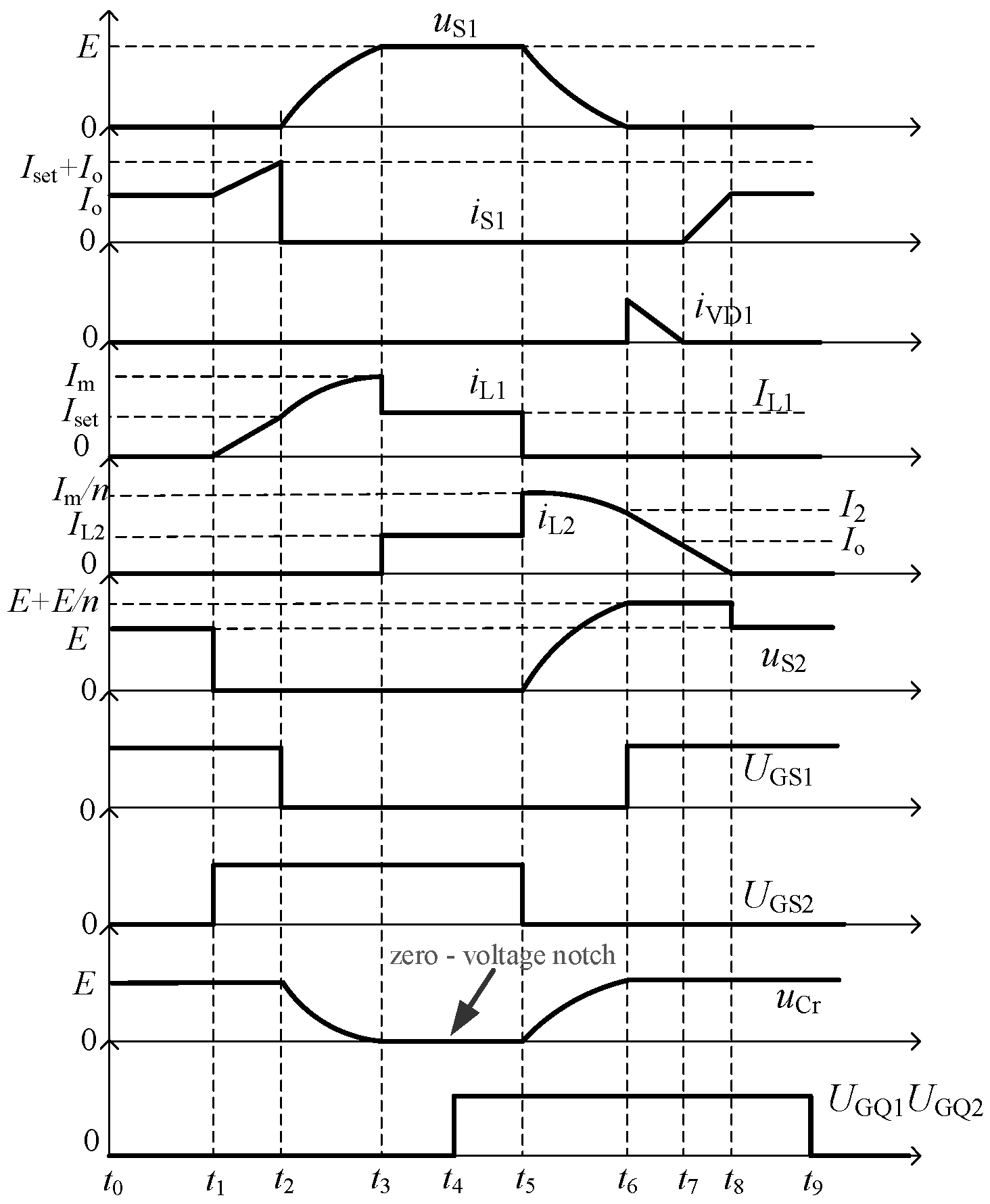
For simplicity, the following assumptions are made: (1) All components operate under ideal conditions; (2) Inductances L1 and L2 are much smaller than the load inductor L, so the load current iL is regarded as a constant value I0 during the switching instant between charging and discharging circuits, with the current direction remaining unchanged. The current amplitude is determined by the duty cycle of the switching transistors in the half-bridge circuit. The reference directions of currents and voltages for L, L1, L2, and Cr follow the arrows in Figure 1. The soft-switching power amplifier operates in 8 states within each switching cycle, with waveforms shown in Figure 2. The eight operating states are categorized into two distinct stages (shown in Figure 3). Stage 1 (States 1–5): This stage is dedicated to generating and maintaining a zero-voltage notch on the DC bus, which is critical for achieving zero-voltage switching (ZVS) of the main switches (Q1 and Q2). Throughout these states, the auxiliary circuit operates to establish and sustain this notch for a duration exceeding the inverter dead time. Stage 2 (States 6–8): This stage focuses on recovering the DC bus voltage to the level of the input voltage and resetting the current and voltage states of the auxiliary resonant components (L1, L2, Cr). This ensures that the system is properly initialized for the subsequent switching cycle. The design goal is to generate a zero-voltage notch in the DC bus voltage uCr, with a duration exceeding the inverter dead time, approximately 5μs in this design.
Operating State 1 (t0t1): Initially, auxiliary switch S1 is on, and the DC power supply transmits energy to the rear-stage bridge circuit through S1.
Operating State 2 (t1t2): Auxiliary switch S2 is turned on at t1. Since the current through resonant inductor L1 cannot change abruptly, the current rise rate across switch S2 is limited, enabling near-zero-current turn-on. After S2 is turned on, the voltage across the inductor L1 is E, and at this point, L1 starts to charge, with its current iL1 increasing linearly. At time t2, iL1 increases to the set current value Iset, and then Operating state 2 ends. In this state, at the moment when the switching transistor S2 is turned on, its current rising rate is:
d i S 2 d t t = t 0 = E L 1
Operating State 3 (t2t3): At time t2, auxiliary switch S1 is turned off. Since the voltage across resonant capacitor Cr cannot change instantaneously, the rate of change in the drain-source voltage of S1 during turn-off is relatively small, approximating zero-voltage turn-off (ZVT). After S1 turns off, inductor L1 and capacitor Cr begin to resonate: Cr discharges while L1 continues to be charged. By time t3, the voltage across Cr decreases to zero, and the current through L1 (iL1) reaches its maximum value Im, marking the end of State 3. The rate of change in the drain-source voltage of S1 at time t2 is:
d u S 1 d t t = t 2 = I set + I o C r
The mathematical expressions for uCr and iL1 are given as follows:
u C r ( t ) = E cos [ ω r 1 ( t t 2 ) ] ( I set + I o ) Z r 1 sin [ ω r 1 ( t t 2 ) ]
i L 1 ( t ) = E Z r 1 sin [ ω r 1 ( t t 2 ) ] + ( I set + I o ) cos [ ω r 1 ( t t 2 ) ] I o
In the above equation, Zr1 represents the characteristic impedance, and ωr1 denotes the resonant angular frequency: Z r 1 = L 1 C r , ω r 1 = 1 L 1 C r .
Operating State 4 (t3t5): At time t3, when the voltage across resonant capacitor uCr decreases to zero, diode VD2 begins to conduct. At this instant, the current through inductor L1 (iL1) transitions abruptly from its maximum value Im to IL1, while the current through inductor L2 (iL2) jumps from zero to IL2. Subsequently, iL1 and iL2 are maintained at IL1 and IL2, respectively. Given that the conduction voltage drops of switch S2 (US2on) and diode VD2 (UVD2on) are both negligible compared to the 48 V DC bus voltage E, the voltage across the resonant capacitor uCr is approximated as zero in this state. During this interval, the main switches Q1 and Q2 of the half-bridge power circuit can complete their state transitions at time t4 under near-zero drain-source voltage conditions, achieving zero-voltage switching (ZVS).
In this state, the duration of the zero-voltage notch of uCr can be flexibly adjusted according to practical requirements. This duration is independent of the values of the resonant inductors, resonant capacitors, and the output current of the load inductor. The currents through resonant inductors L1 and L2 in this state are, respectively:
I L 1 = I m n I o 1 + n
I L 2 = I m + I o 1 + n
Operating State 5 (t5t6): At time t5, auxiliary switch S2 is turned off. Since the voltage across resonant capacitor Cr cannot change instantaneously, the rate of change in the drain-source voltage of S2 during turn-off is sufficiently small to approximate zero-voltage turn-off (ZVT). At the instant S2 turns off, the current through inductor L2 (iL2) transitions abruptly from IL2 to Im/n (where n is the turns ratio of L2 to L1). Subsequently, L2 and Cr begin to resonate: L2 discharges with iL2 decreasing gradually, while Cr charges and uCr increases from zero. Simultaneously, L2 discharges energy to the load inductor of the bridge circuit, causing the load current to increase. By time t6, iL2 decreases to I2 and uCr rises to the bus voltage E, marking the end of Mode 5. The rate of change in the drain-source voltage of S2 at t5 is:
d u S 2 d t t = t 5 = I m / n I o C r
In this state, the mathematical expressions for uCr and iL2 are as follows:
u C r ( t ) = Z r 2 ( I m n I o ) sin [ ω r 2 ( t t 5 ) ] n
i L 2 ( t ) = I m n I o cos [ ω r 2 ( t t 5 ) ] + I o
In the above equations, Zr2 denotes the characteristic impedance, and ωr2 represents the resonant angular frequency. Among them, Z r 2 = n Z r 1 = L 2 C r , ω r 2 = ω r 1 n = 1 L 2 C r .
Operating State 6 (t6t7): At time t6, the diode VD1 in parallel with switch S1 begins to conduct. When S1 is turned on at this instant, it achieves approximate zero-voltage switching (ZVS). After VD1 conducts, the voltage across inductor L2 equals the bus voltage E, causing the current iL2 to decrease linearly from Ia (the current through L2 at t6). By time t7, iL2 decreases to the load current Io, leading to the turn-off of VD1 and the end of State 6. The mathematical expression for the current iL2 through L2 in this state is:
i L 2 ( t ) = I a E L 2 ( t t 6 )
In the above equation, I a = I o + ( I m n I o ) 2 Z r 2 E 2 n Z r .
Operating State 7 (t7-t8): At time t7, switch S1 starts to conduct, and the current iL2 through inductor L2 continues to decrease linearly. By time t8, when iL2 linearly decreases to zero, State 7 ends. The mathematical expression for iL2 in this state is:
i L 2 ( t ) = I o E L 2 ( t t 7 )
Operating State 8 (t8t9): By time t8, the auxiliary resonant circuit has completed all operations within one switching cycle. The currents through resonant inductors L1 and L2 return to their initial values, while the voltage across the resonant capacitor remains at the bus voltage E. In this state, both main switches Q1 and Q2 are conducting, allowing the current through the load inductor L to continue increasing. At time t9, Q1 and Q2 are turned off. Since the voltages across capacitors C1 and C2 cannot change instantaneously, Q1 and Q2 approximately achieve zero-voltage turn-off (ZVT).

2.3. Selection of Key Parameters

In designing the auxiliary resonant circuit for a soft-switching power amplifier, the selection of key parameters is critical to system performance. The following discusses in detail how to appropriately choose parameters such as the resonant capacitor, turns ratio of resonant inductors, and inductance values from three perspectives:
(1)
To ensure that auxiliary switches S1 and S2 achieve zero-voltage turn-off (ZVT) with minimal voltage rise rates at turn-off instants, the selected values of current setpoint Iset, resonant inductor L1, and resonant capacitor Cr must satisfy the condition that the voltage rise rates of S1 and S2 do not exceed permissible limits.
(2)
To enable main switches Q1 and Q2 of the half-bridge circuit to turn on under zero-voltage conditions, the parameters Iset, L1, and Cr must be chosen such that the DC bus voltage is effectively reduced to zero. According to Equation (3), the selection of these three parameters shall satisfy:
I set E Z r 1 I o
(3)
To achieve zero-voltage turn-on (ZVT) for switch S1, the selected values of current setpoint Iset, resonant inductor L1, resonant capacitor Cr, and turns ratio n of coupled resonant inductors must ensure that the DC bus voltage can recover to the supply voltage during resonance. Based on Equation (8), these four parameters should satisfy the following relationship:
I set E Z r 1 + ( n + 1 ) I 0 2 E Z r 1 2 I 0
Considering the above three conditions, the final selected parameters are: current setpoint Iset = 10 A, resonant inductor L1 = 50 μH, resonant capacitor Cr = 200 pF, and turns ratio of coupled resonant inductors n = 1. With these parameters, all switching devices in the circuit topology achieve soft-switching transitions, which effectively reduce energy loss during switching, improve system efficiency, and minimize heat generation and device wear.

2.4. Operating Bandwidth

The operating bandwidth of a switched power amplifier for active magnetic bearings is a critical indicator of its performance, directly influencing system stability and response speed. It is affected by multiple factors, with the following two being primary:
  • Switching frequency is a key determinant of bandwidth. A higher switching frequency can enhance bandwidth but introduces increased switching losses, thereby reducing system efficiency. Typically, the switching frequency fk should be more than 10 times the upper cutoff frequency of the power amplifier.
f k 10 f c
In this study, the designed operating bandwidth of the switched power amplifier is 1 kHz, so the switching frequency needs to exceed 10 kHz. Given the adoption of soft-switching technology, which allows for a moderate increase in switching frequency, subsequent experimental verification confirms that a final switching frequency of 50 kHz is selected.
2.
The bandwidth of a switching amplifier reflects its current response speed. A higher bus voltage enables faster current response, as the bandwidth increases with bus voltage. However, while elevated bus voltage improves bandwidth, it simultaneously increases current ripple. The expression for current response speed is given as follows:
d i d t = V in 2 U on R i L
where Vin is the bus voltage, Uon is the conduction voltage drop of the switch, i is the coil current, Ri is the voltage drop across the coil resistance, and L is the coil inductance. Since the value of Vin is much larger than the conduction voltage drop of the switch, and the equivalent resistance R of the coil is very small, these two terms can be neglected. For an active magnetic bearing coil with a fixed structure, its equivalent inductance L is a fixed value; therefore, it can be approximately considered that the current response speed of the power amplifier is proportional to the bus voltage. Considering the constraint of the current ripple, the bus voltage in this paper is set to 48 V.

3. Control Method

Based on the control of the half-bridge circuit in traditional hard-switching power amplifiers, this paper further requires controlling the state transitions of the auxiliary switches. The following sections, respectively, introduce the control methods for the two main switches of the power half-bridge circuit and the two auxiliary switches of the auxiliary resonant circuit.

3.1. Control of Main Switches in Power Half-Bridge Circuit

In the half-bridge power circuit, PWM (Pulse Width Modulation) is employed [11]. The operating principle is as follows: the error signal is generated by subtracting the feedback signal from the reference signal, which is then processed by a PI controller to produce a sinusoidal-like modulation wave. This modulation wave is compared with a fixed-frequency, fixed-amplitude triangular carrier wave to generate the gate drive signals for the switching devices. When the power amplifier system delivers constant current through the load inductor, the PWM waveform appears as shown in Figure 4, with a switching frequency of 35 kHz. In Figure 4, the rectangular wave represents the PWM signal, the sine wave denotes the modulation wave output from the PI control module, and the sawtooth wave indicates the fixed-frequency, fixed-amplitude triangular carrier wave. When the modulation wave exceeds the carrier wave, a high-level output is generated, indicating the switching devices are in the ON state; conversely, a low-level output turns off the switches. A PWM duty cycle exceeding 50% means the charging time of the load coil exceeds its discharging time within one switching period, causing the coil current to continuously rise. Conversely, when the duty cycle is below 50%, the coil current decreases.

3.2. Control of Switches in Auxiliary Resonant Circuit

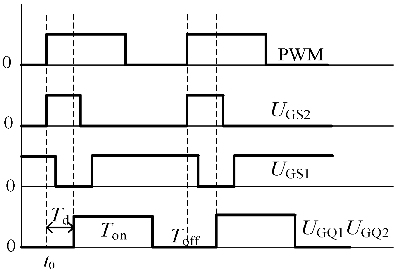
This paper proposes a soft-switching power amplifier, where the auxiliary resonant circuit features advantages such as a simple structure, fewer components, and ease of control. The specific logic control of the auxiliary resonant circuit is illustrated in Figure 5 above. When the main switches Q1 and Q2 in the half-bridge circuit need to switch their states, a certain delay time Td is required. This delay ensures that the state transition occurs within the zero-voltage trough, thereby reducing switching losses. Notably, Td is not a fixed value and can be flexibly adjusted during experimental tests. At time t0, auxiliary switch S2 is turned on; after a certain period, auxiliary switch S1 is turned off. When the voltage across Cr (uCr) drops to zero, the main switches Q1 and Q2 can start to conduct, achieving zero-voltage turn-on (ZVS) at this instant. After uCr remains at zero for a period, auxiliary switch S2 is turned off. When uCr rises to the bus voltage, auxiliary switch S1 is turned on. In Figure 5, when the drive signals GQ1 and GQ2 transition from a high level to low level, the voltage across the capacitors paralleled with Q1 and Q2 cannot change instantaneously, enabling Q1 and Q2 to achieve zero-voltage turn-off (ZVT) as well.

4. Simulation and Experiment

Next, simulation analysis and experimental testing will be conducted to verify the feasibility and effectiveness of the proposed soft-switching power amplifier circuit. The relevant component parameters are as follows: input DC bus voltage of 48 V, maximum output current of the electromagnetic coil at 5 A, resonant inductors L1 = 50 μH and L2 = 50 μH, resonant capacitor Cr = 200 pF, equivalent inductance of the electromagnetic coil L = 4 mH, and switching frequency of 50 kHz.

4.1. Verification of Soft-Switching Effect

To validate the feasibility of the soft-switching power amplifier, Multisim circuit simulation software is utilized. By comparing the operating waveforms of the main switches Q1 and Q2 between the soft-switching and hard-switching power amplifiers, this section illustrates how the soft-switching topology reduces system switching losses. Since Q1 and Q2 turn on/off simultaneously and exhibit identical switching losses, only Q1 is analyzed in detail for simplicity.
As shown in Figure 6a, in the hard-switching power amplifier, when the gate drive signal of Q1 rises (during turn-on), the drain-source voltage of Q1 equals the 48 V bus voltage. In practical circuits, the transition from the off-state to the on-state for a switch requires a certain duration (typically 100 ns), during which the drain-source voltage and the conduction current of Q1 overlap partially. This overlapping region corresponds to the turn-on loss of the switching device. Similarly, the transition from the on-state to the off-state also takes a certain time (typically 200 ns), and the overlapping region in this process represents the turn-off loss.
Shown in Figure 6b, in the soft-switching power amplifier, switch Q1 turns on under the zero-voltage trough condition. At this moment, there is no overlapping region between the drain-source voltage of Q1 and the conducting current, indicating that Q1 achieves zero-voltage turn-on (ZVS), thus reducing switching losses. During the turn-off process of Q1, the voltage across the parallel capacitor cannot change instantaneously, enabling zero-voltage turn-off (ZVT). A comparison between Figure 6a,b reveals that, in theory, the soft-switching power amplifier can reduce the electrical energy loss caused by the state transitions of switching devices, thereby improving the operating efficiency of the system.
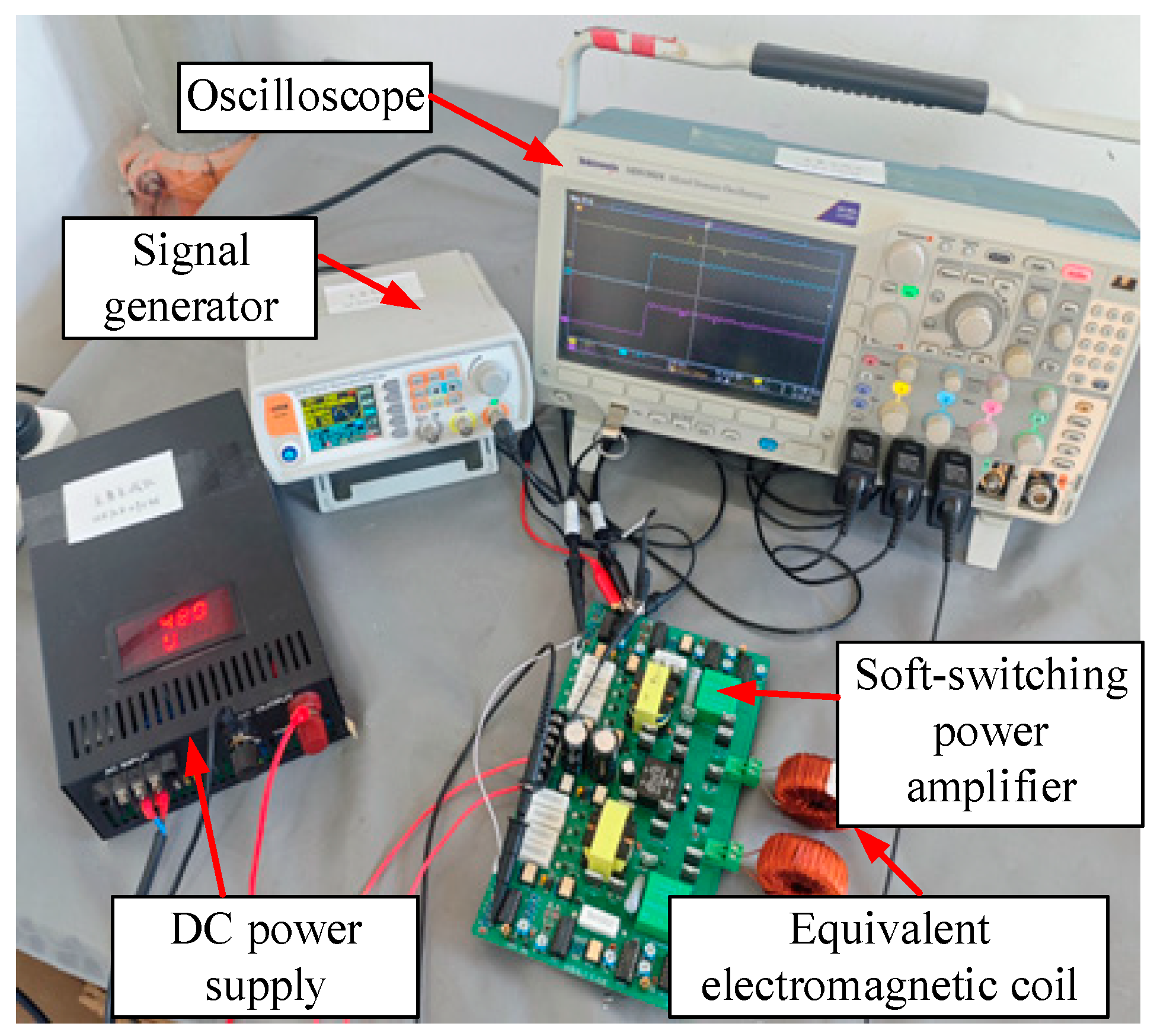
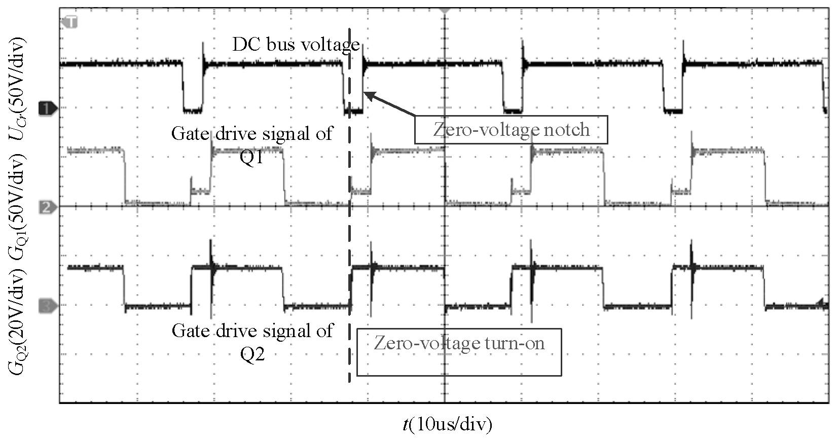
Further verify the effectiveness of the soft-switching power amplifier circuit, tests were conducted on the fabricated soft-switching power amplifier circuit board, with the experimental prototype shown in Figure 7. The experimental setup was supplied with 48 V DC, and an equivalent coil simulating the inductive load characteristics of an actual electromagnetic bearing (with an equivalent inductance L = 4 mH) was employed as the load. A DC reference voltage or sinusoidal signal, emulating the control command for the electromagnetic bearing, was introduced via a signal generator. Waveforms including the gate drive voltages of the switching transistors Q1 and Q2, as well as the load current, were captured using an oscilloscope. These measurements were used to validate the achievement of zero-voltage switching, the reduction in switching losses, and to assess whether the efficiency and dynamic performance of the soft-switching power amplifier met the expected design targets. The soft-switching performance of the proposed power amplifier was rigorously evaluated through an integrated workflow encompassing simulation-based prediction and experimental validation. As complementary components of this verification process, Figure 6 (simulation waveforms) and Figure 7 (experimental prototype) are intrinsically linked: both collectively demonstrate the successful achievement of zero-voltage switching (ZVS) in the main switches (Q1 and Q2), enabled by the zero-voltage notch generated from the auxiliary resonant circuit, which effectively eliminates switching losses. The simulation model incorporates the same key parameters as the physical prototype to ensure consistency and predictive accuracy. Moreover, while Figure 6 offers detailed insight into the switching behavior of Q1 at a microscopic level, Figure 7 corroborates the practical implementation of the topology and confirms the ZVS effect anticipated by simulation. The specific experimental waveforms are presented in Figure 8, where the three channels from top to bottom correspond to the DC bus voltage, the gate drive voltage of switch Q1, and the gate drive voltage of switch Q2, respectively. As observed in Figure 8, a zero-voltage trough appears in the bus voltage, indicating that a zero-voltage interval exists across the drain-source terminals of Q1 and Q2. During this interval, Q1 and Q2 complete their state transitions under zero-voltage conditions, thereby reducing switching losses. This result is consistent with the simulation findings, confirming the effectiveness of the proposed soft-switching power amplifier.

4.2. Efficiency Comparison Between Hard-Switching and Soft-Switching Power Amplifiers

The efficiency of the power amplifier can be evaluated by comparing the output current flowing through the electromagnetic coil with the input current drawn from the 48 V DC power supply. The term “efficiency” used herein refers to power conversion efficiency. The specific efficiency calculation formula is given as follows:
η = P t o t a l P l o s s P t o t a l = V in I i n P l o s s V in I i n
In the equation, Ptotal represents the total input power of the power amplifier system, Vin is the 48 V DC power supply voltage, Iin denotes the current input from this power supply to the power amplifier, and Ploss refers to various system losses. These losses include those generated during the state transitions of switching devices, losses induced by the equivalent resistance of the electromagnetic coil, and conduction losses of switches and diodes. A higher switching frequency of the power amplifier’s switches leads to increased losses, which in turn reduces the overall efficiency of the system.
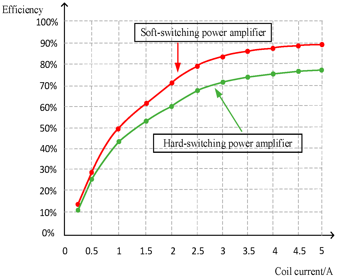
Under the condition of outputting the same coil current, a smaller required input current indicates higher efficiency of the power amplifier system. Figure 9 shows the efficiency comparison curves between the soft-switching power amplifier and the hard-switching power amplifier when the switching frequency of the switches is 50 kHz. As can be seen from Figure 9, the efficiency of the power amplifier is related to the output current of the electromagnetic coil: the larger the output current, the higher the efficiency of the corresponding power amplifier system. Taking an output current of 3 A as an example, the efficiency of the soft-switching power amplifier proposed in this paper can be improved by approximately 10% compared with that of the traditional hard-switching power amplifier.

4.3. Dynamic Performance Test of the Soft-Switching Power Amplifier

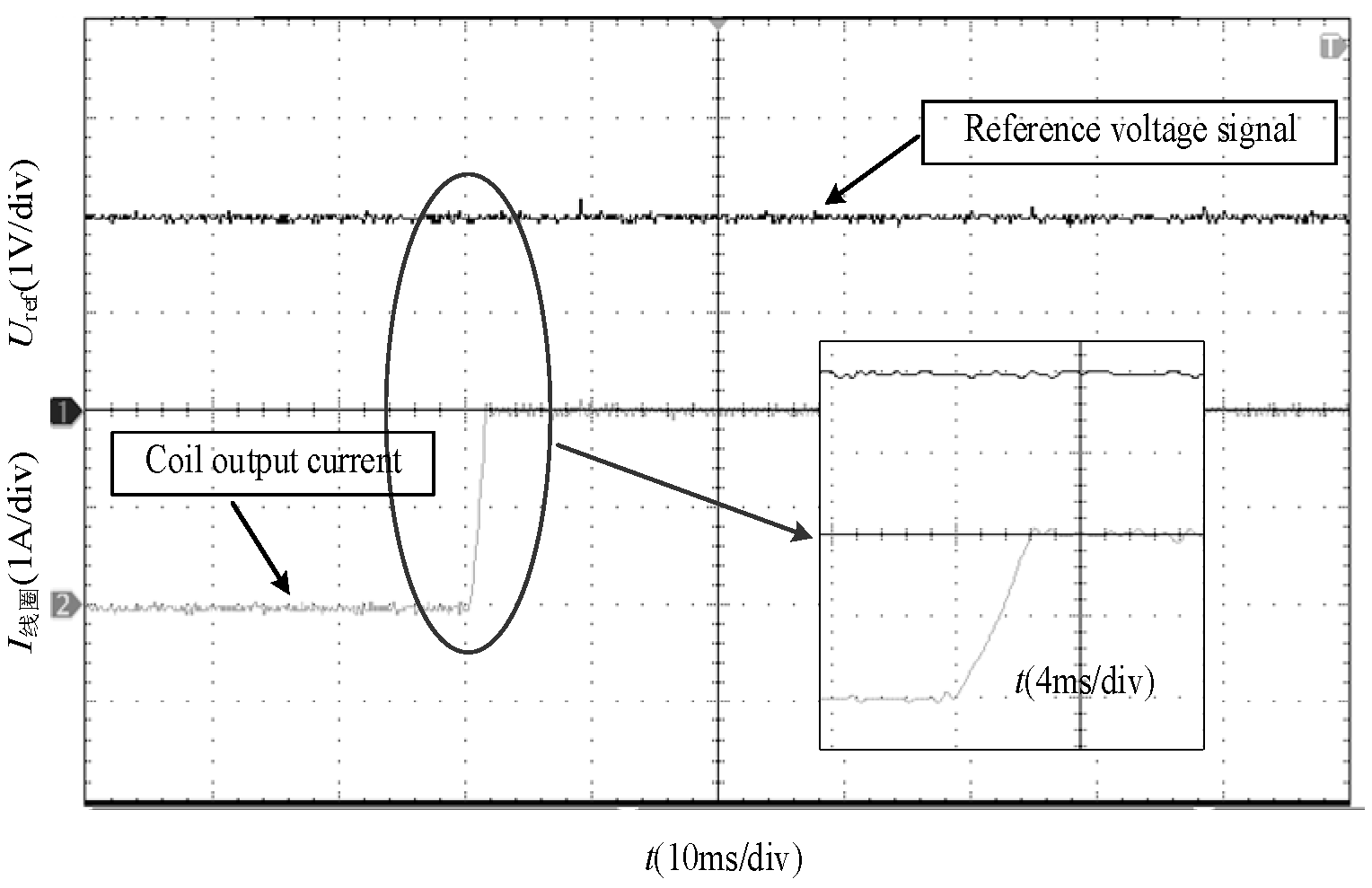
To further investigate the dynamic response characteristics of the soft-switching power amplifier and verify whether the addition of the auxiliary resonant circuit affects the dynamic performance of the power amplifier system, an experiment was conducted under the following conditions: a 2 V DC reference voltage was applied, and the switching frequency of Q1 and Q2 was set to 50 kHz. Figure 10 above presents the step response curve of the soft-switching power amplifier system. As observed from Figure 10, the settling time of the step response is approximately 2 ms, the output current of the electromagnetic coil stabilizes at around 2 A, and the amplitude of the current ripple is approximately 100 mA. These results indicate that the system exhibits rapid dynamic response capability, small current ripple, and low overshoot, which well meet the design requirements. The hardware prototype, implemented based on the parameters optimized through theoretical analysis in Section 2.3, exhibits a 10% improvement in efficiency at a 3 A output (Figure 9) and a step-response settling time of approximately 2 ms (Figure 10). These results collectively demonstrate the validity of the theoretical design approach.
As the switching frequency and bus voltage of the power amplifier increase, the resulting high-frequency electromagnetic noise becomes a more significant source of interference to the system, potentially compromising its stability. Figure 11 below depicts the output current waveform of the electromagnetic coil when a 200 Hz sinusoidal reference voltage is applied and the switching frequency of the power devices is set to 50 kHz.
As shown in Figure 11a, the output signal of the traditional hard-switching power amplifier contains a large amount of noise, resulting in an unsatisfactory output waveform. It can be observed from Figure 11b that in the soft-switching power amplifier proposed in this paper, when the switching devices operate at a relatively high switching frequency, the output current waveform of the electromagnetic coil is smooth, with a coil current ripple of approximately 100 mA, which effectively suppresses high-frequency electromagnetic interference.
Finally, the operating bandwidth of the power amplifier was tested. Under the condition that the given reference voltage is a 1 kHz sinusoidal signal, the output current waveform of the electromagnetic coil is shown in Figure 12 below. It can be seen from Figure 12 that the amplitude of the output current does not attenuate, there is no obvious phase lag, and the tracking performance is excellent. Through tests with multiple groups of sinusoidal signals with different frequencies, the cutoff frequency of the power amplifier is finally measured to be approximately 1300 Hz, which can meet the requirements of the electromagnetic bearing for the operating bandwidth of the power amplifier. The measured cutoff frequency of approximately 1300 Hz (Figure 12) not only exceeds the target bandwidth specification of 1 kHz but also provides experimental validation for the theoretical relationship described by Equation (14). The selected switching frequency of 50 kHz aligns well with the theoretical constraint outlined in Section 2.3. Moreover, the stable sinusoidal tracking performance observed at 1 kHz confirms. These results collectively provide strong experimental support for the bandwidth-related theoretical analysis of the proposed amplifier.

5. Conclusions

Through theoretical analysis, simulation, and experiment results in this paper, the following conclusions can be drawn:
(1)
A soft-switching power amplifier topology for active magnetic bearing is proposed. This topology enables the switches of the half-bridge circuit to turn on when the bus voltage is zero, effectively reducing switching losses.
(2)
Compared with the traditional hard-switching power amplifier, the proposed soft-switching power amplifier achieves higher system efficiency. Specifically, with an output current of 3 A, the efficiency of the soft-switching power amplifier can be enhanced by 10%.
(3)
The proposed soft-switching power amplifier system exhibits a response time of approximately 2 ms, indicating excellent dynamic performance. Since all switches complete state transitions under zero-voltage conditions, the output current waveform of the electromagnetic coil remains smooth even at high switching frequencies, effectively suppressing high-frequency current noise. The novelty of this work is mainly reflected in the following three aspects: a novel topology design, a breakthrough in balanced performance, and a close correlation between simulation and experiment.
Novel Topology Design: In contrast to the complex and difficult-to-control topology presented [14] and the narrow zero-voltage window topology [15], the proposed structure incorporates only a compact auxiliary resonant circuit (L1 = 50 μH, L2 = 50 μH, Cr = 200 pF, and auxiliary switches S1/S2) into a conventional hard-switching half-bridge inverter. A key innovation is the flexibly adjustable duration of the zero-voltage notch on the DC bus, which remains independent of load current variations, offering significantly improved practicality for AMB systems.
Balanced Performance Breakthrough: While existing solutions tend to prioritize either current control accuracy or dynamic response, the proposed amplifier achieves a well-balanced performance profile: it exhibits a 10% improvement in efficiency at a 3 A output, suppresses high-frequency current ripple to approximately 100 mA, maintains satisfactory dynamic performance, and provides sufficient bandwidth. This effectively bridges the performance trade-off gap commonly encountered in soft-switching power amplifiers for AMB applications.
Correlation Between Simulation and Experiment: The simulation model, implemented in Multisim, was instrumental in verifying the soft-switching mechanism and guiding the selection of critical hardware parameters such as resonant components and switching frequency. Experimental results closely align with simulation predictions, demonstrating consistency between the theoretical design and practical implementation.
To further evaluate the advantages of the proposed topology against recently published works, Table 1 presents a systematic comparison with several recent soft-switching power amplifier approaches for AMBs.

Author Contributions

Conceptualization: H.D., M.Z. and L.C.; Methodology: H.D., Z.H. and L.C.; Software: Q.C., X.X. and L.C.; Formal analysis: Q.C., X.X., P.L. and L.C.; Data curation: H.D., P.L. and L.C.; Writing—original draft preparation: M.Z.; Writing—review and editing: H.D., M.Z. and L.C. All authors have read and agreed to the published version of the manuscript.

Funding

Project supported by the National Natural Science Foundation of China Grant (52565024).

Data Availability Statement

The data presented in this study are available on request. Further inquiries can be directed to the corresponding authors.

Acknowledgments

The authors gratefully acknowledge the financial support from the National Natural Science Foundation of China Grant (52565024). We are deeply grateful for the funding that enabled the realization of this research.

Conflicts of Interest

The authors declare no conflicts of interest.

References

  1. Xingjian, D.; Kunpeng, W.; Xiaozhang, Z.; Jiang, X.; Zhang, K. Fifty years review of flywheel energy storage technology research. Energy Storage Sci. Technol. 2018, 7, 765–782. (In Chinese) [Google Scholar]
  2. Gong, J.; Zhang, G.; Zhang, J.; Wu, H.; Cheng, X. Design of digital switching power amplifier for magnetic suspended bearing. In Proceedings of the 2013 Chinese Intelligent Automation Conference, Yangzhou, China, 24 July 2013; Springer: Berlin/Heidelberg, Germany, 2013; pp. 733–739. [Google Scholar]
  3. Liangliang, C.; Changsheng, Z.; Zhongbo, W. Two degree of freedom control of electromagnetic bearing flywheel rotor system based on inverse system decoupling. Trans. China Electrotech. Soc. 2017, 32, 100–114. (In Chinese) [Google Scholar]
  4. Chen, L.; Zhu, C.; Zhong, Z.; Wang, C.; Li, Z. Radial position control for magnetically suspended high-speed flywheel energy storage system with inverse system method and extended 2-DOF PID controller. IET Electr. Power Appl. 2020, 14, 71–81. [Google Scholar] [CrossRef]
  5. Sahinkaya, M.N.; Hartavi, A.E. Variable bias current in magnetic bearings for energy optimization. IEEE Trans. Magn. 2007, 43, 1052–1060. [Google Scholar] [CrossRef]
  6. Chengzi, L.; Zhisheng, X.; Yan, Y.; Zeyuan, L.; Hui, G.; Yuan, G. A fault-tolerant multi bridge arm switching power amplifier circuit applied to magnetic levitation bearings. Proc. CSEE 2023, 43, 6828–6840. (In Chinese) [Google Scholar]
  7. Liu, C.; Zhan, J.; Wang, J.; Yang, Y.; Liu, Z. An improved one-cycle control algorithm for a five-phase six-leg switching power amplifier in active magnetic bearings. IEEE Trans. Ind. Electron. 2022, 69, 12564–12574. [Google Scholar] [CrossRef]
  8. Yiwei, Y.; Min, C.; Dehong, X. Research on wave by wave current limiting control strategy for soft switching active clamp inverter. J. Power Supply 2024, 22, 43–50. (In Chinese) [Google Scholar]
  9. Singh, J.P.; Kumar, S.S.; Kumar, D.; Lalitha, A.S. A soft switching boost DC-DC converter based on ZVS for vehicle to grid applications with enhanced efficiency. In Proceedings of the 2022 IEEE Region 10 Symposium (TENSYMP), Mumbai, India, 1–3 July 2022; pp. 1–6. [Google Scholar]
  10. Qiang, W.; Youzheng, W.; Tianshi, W.; Xiaoqin, L. Simple control energy-saving single-phase full bridge inverter. Acta Electron. Sin. 2023, 43, 6828–6840. (In Chinese) [Google Scholar]
  11. Jiang, D.; Li, T.; Hu, Z.; Sun, H. Novel topologies of power electronics converter as active magnetic bearing drive. IEEE Trans. Ind. Electron. 2019, 67, 950–959. [Google Scholar] [CrossRef]
  12. Hsieh, H.C.; Nguyen, A.D.; Lai, J.S. Low noise ZVS switch sharing multichannel switching amplifier for magnetic bearing applications. IEEE Trans. Circuits Syst. II 2020, 67, 1999–2003. [Google Scholar] [CrossRef]
  13. Hsieh, H.C.; Nguyen, A.D.; Lai, J.S. Soft switching multichannel magnetic bearing amplifier with reduced number of switches. IEEE Trans. Control. Syst. Technol. 2019, 14, 937–942. [Google Scholar]
  14. Jun, W.; Longxiang, X. Application of soft switching technology in magnetic suspension bearing power amplifier. Trans. China Electrotech. Soc. 2009, 24, 85–90. (In Chinese) [Google Scholar]
  15. Xiang, Z. Research on a New Soft Switching Power Amplifier for Magnetic Bearings. Master’s Thesis, Hunan University, Changsha, China, 2022. (In Chinese). [Google Scholar]
  16. Enhui, C.; Yunqi, K.; Jingjing, L. A novel SVPWM method for parallel resonant DC link inverters. Proc. CSEE 2022, 42, 2321–2334. (In Chinese) [Google Scholar]
  17. Li, Y.; Zhang, Q.; Liu, Y.; Wang, C. Series resonant soft-switching power amplifier for active magnetic bearings: Design and analysis. IEEE Trans. Ind. Electron. 2022, 69, 8210–8220. [Google Scholar]
  18. Wang, H.; Chen, L.; Li, J.; Zhao, T. Active-clamped soft-switching topology for magnetic bearing power amplifiers: Loss analysis. In Proceedings of the 49th Annual Conference of the IEEE Industrial Electronics Society (IECON 2023), Singapore, 16–19 October 2023; pp. 1–6. [Google Scholar]
  19. Zhang, L.; Li, X.; Feng, G. Zero-voltage switching control for magnetic bearing power amplifiers: Dead-time compensation. J. Power Electron. 2021, 21, 456–465. [Google Scholar]
  20. Chen, Z.; Sun, Y.; Lu, Y. Model predictive control for soft-switching power amplifiers in magnetic bearings: Reducing computational complexity. IEEE Trans. Control. Syst. Technol. 2024, 32, 412–423. [Google Scholar]
  21. Kim, J.; Park, S.; Choi, S. A compact soft-switching power amplifier for magnetic bearings: Integrating resonant circuit with coil inductance. IEEE Trans. Magn. 2020, 56, 1. [Google Scholar] [CrossRef]
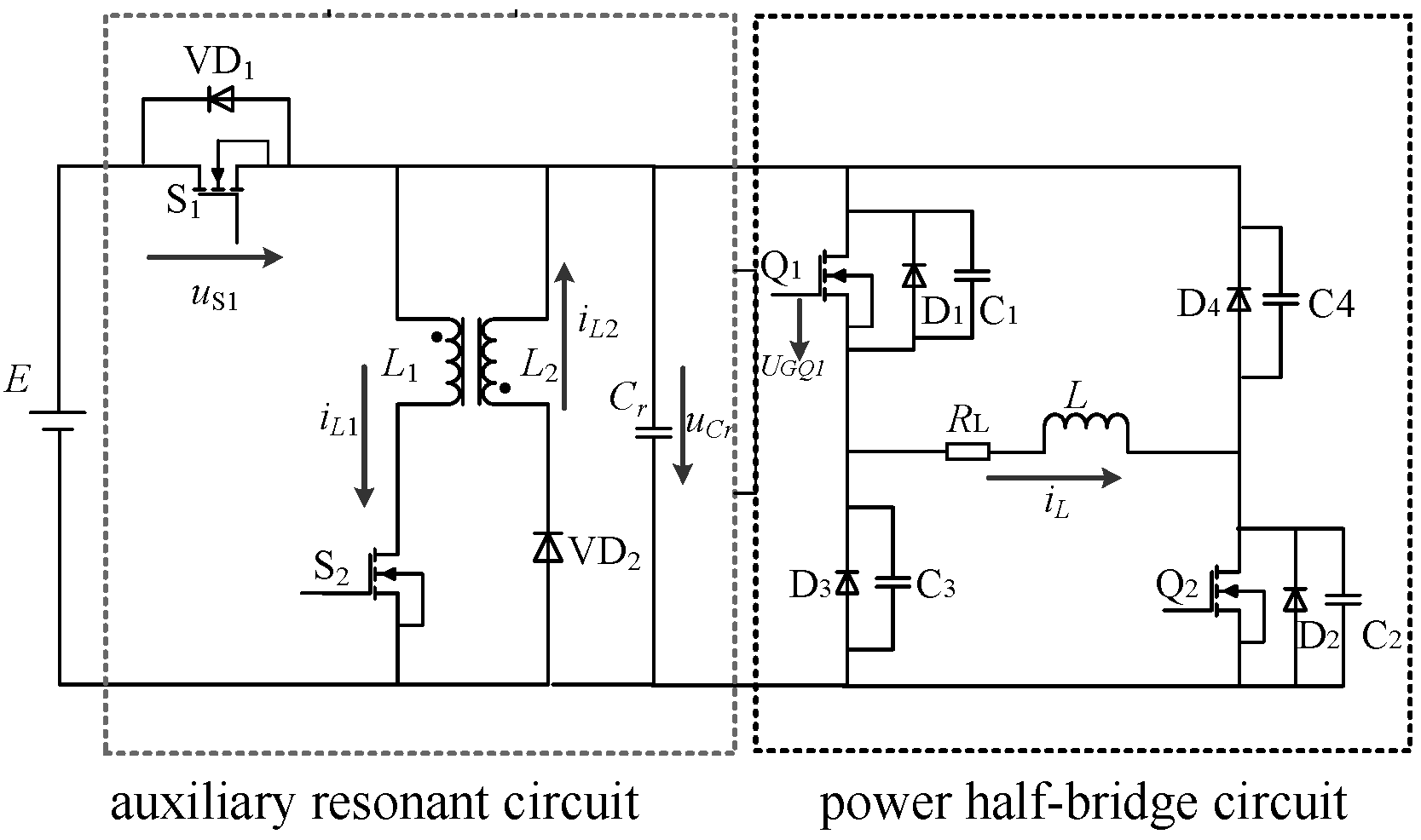
Figure 1. Topology of the soft-switching power amplifier circuit.
Electronics 14 03858 g001
Figure 2. Working waveform of soft switching power amplifier.
Electronics 14 03858 g002
Figure 3. Circuit diagram of eight operation states.
Electronics 14 03858 g003
Figure 4. PWM waveform at steady state.
Electronics 14 03858 g004
Figure 5. Control timing diagram of auxiliary resonant circuit.
Electronics 14 03858 g005
Figure 6. Comparison of current and voltage waveforms of switch Q1 in simulation. (a) Hard-switching power amplifier. (b) Soft-switching power amplifier.
Electronics 14 03858 g006
Figure 7. Experimental prototype diagram.
Electronics 14 03858 g007
Figure 8. Experimental waveform of the conduction process of switch transistors Q1 and Q2.
Electronics 14 03858 g008
Figure 9. Efficiency comparison vs. output current.
Electronics 14 03858 g009
Figure 10. Step response of soft switching power amplifier.
Electronics 14 03858 g010
Figure 11. Comparison of output current under sine input conditions of power amplifier. (a) hard—switching power amplifier; (b) soft—switching power amplifier.
Electronics 14 03858 g011
Figure 12. Output curve of power amplifier under given signal of 1 kHz sine wave condition.
Electronics 14 03858 g012
Table 1. Performance Comparison of Recent Soft-Switching Power Amplifiers for AMBs.
Reference
(Author, Year)
Topology/Control Strategy TypeCore AdvantagesKey Limitations/DefectsApplicability Restrictions for AMBsMost Salient Results
Li et al., 2022 [17]Series Resonant TopologyAchieves zero-voltage switching (ZVS) via resonance between coil inductor and auxiliary capacitor.
Reduces switching losses by 15%.
Resonant frequency depends on load current: frequency fluctuates by 20 kHz when AMB load current increases from 1 A to 5 A, requiring real-time adjustment of control parametersLimited engineering applicability due to load-dependent resonant frequencySwitching losses reduced by 15%; resonant frequency fluctuation: 20 kHz (1 A–5 A load current)
Wang et al., 2023 [18]Active-Clamped Soft-Switching TopologyAbsorbs DC bus voltage spikes via a clamping capacitor.
Realizes ZVS.
Auxiliary circuit requires 2 additional power transistors and 1 clamping capacitor.
Increases circuit losses by 5% (caused by charging/discharging losses of the clamping capacitor)
Inapplicable to high-frequency (>50 kHz) switching scenarios of AMBsAbsorbs bus voltage spikes; auxiliary circuit increases losses by 5%; not suitable for operation above 50 kHz
Zhang et al., 2021 [19]ZVS Control with Dead-Time CompensationAddresses the coupling relationship between dead time and soft switching.
Proposes a dead-time compensation algorithm.
Verifies the necessity of zero-voltage duration covering dead time.
Does not provide a specific topology implementation (only focuses on control strategy)Cannot be directly applied to hardware integration of AMB PAs due to lack of topology designValidates that zero-voltage duration must cover dead time; no specific efficiency/power performance data
Chen et al., 2024 [20]Model Predictive Control (MPC) for Soft-SwitchingImproves the dynamic response of soft-switching PAs.Excessive computational complexity,
Requires FPGA hardware support, leading to increased costs
Not cost-effective for low-to-medium budget AMB systems; high hardware threshold limits popularizationEnhances dynamic response; requires FPGA for implementation; no quantifiable efficiency/bandwidth data
Kim et al., 2020 [21]Compact Soft-Switching Topology (Resonant Circuit + Coil Inductance Integration)Integrates resonant circuit with coil inductance, simplifying the overall structure of the PA.Resonant characteristics rely on AMB coil inductance (coil inductance of AMBs may fluctuate with operating conditions, affecting resonant stability)Resonant performance is susceptible to AMB coil inductance variations, reducing stability in variable-load AMB scenariosSimplifies PA structure; resonant stability affected by coil inductance fluctuations; no specific efficiency improvement data
This WorkParallel Resonant Soft-Switching Topology1. Compact auxiliary resonant circuit, easy to implement.
2. Zero-voltage notch duration is adjustable and independent of load current.
3. All switches achieve ZVS, significantly reducing switching losses. 4. Balances efficiency, dynamic performance, and operating bandwidth without performance trade-offs.
No significant limitations; auxiliary circuit introduces negligible additional losses, but requires precise timing controlNo restrictions; suitable for AMBs with variable load current and high-frequency (50 kHz) switching requirements1. Efficiency: improved by 10% at 3 A output current; 2. Switching frequency: 50 kHz; 3. Dynamic response: settling time of ~2 ms; 4. Current ripple: ~100 mA; 5. Operating bandwidth: cutoff frequency of ~1300 Hz; 6. All switches achieve ZVS, eliminating voltage-current overlap during switching, improve system efficiency
Disclaimer/Publisher’s Note: The statements, opinions and data contained in all publications are solely those of the individual author(s) and contributor(s) and not of MDPI and/or the editor(s). MDPI and/or the editor(s) disclaim responsibility for any injury to people or property resulting from any ideas, methods, instructions or products referred to in the content.