1. Introduction
The medium-low speed magnetic levitation (maglev) rail transit system has a series of advantages, such as no wheel–rail contact, low noise, low energy consumption, low maintenance cost, safety and comfort, etc. The maglev train is particularly suitable for short and medium distance transportation between and within cities. It will become one of the ideal choices for urban rail transit systems, and will be “seamlessly connected” to railways, airports and other transportation systems. China established the first self-developed medium-low speed maglev transportation system in Changsha, Hunan [
1]. It connects two major transportation hubs of Changsha High-speed Railway South Station and Changsha Huanghua Airport Station to provide passengers with safe, fast and comfortable transportation.
Although the maglev train is in a suspended state, its power supply method is still through the contact between the current receiver and the power rail. Their contact state will produce different degrees of deviation and swing as the train’s different operating conditions change, resulting in the phenomenon of offline electric arcs. Offline electric arcs will radiate electromagnetic waves into the surrounding space, which may affect the normal operation of sensitive electronic equipment around the train [
2,
3].
Nowadays, there is a lot of research on the offline electric arc of railway transportation systems. These electric arcs can be divided into two types according to the contact mode. One is the electric arc generated by the contact between the pantograph and the contact wire, and the other is the arc generated by the contact between the power receiving shoe and the power supply rail. The first type of electric arc occurs mainly in high-speed electrified railways. In [
4], it is found that rising/dropping pantograph will cause different electric arc radiation interference. In [
5,
6], the physical characteristics of pantograph arcing are studied by constructing a simulation model. In [
7], Huang et al. proposed a new arc modeling framework that takes into account the dynamic variation in arc length as well as the processes of extinction and reignition, and analyzed how these processes affect vehicle overvoltages and electromagnetic interference (EMI). In [
8,
9], the influence of pantograph arcing on the vehicle body voltage is studied by constructing the vehicle-network model’s simulation. In [
10,
11], there are systematic investigations of the effects of various parameters on the wideband radiated emission of pantograph arcing in a laboratory simulation system. Yunfeng Li et al. [
12] developed a real-time EMI measurement technique based on multi-antenna synchronous acquisition and blind source separation, enabling high-precision monitoring of electromagnetic radiation from high-speed maglev trains, with a noise suppression effect of up to 20 dB. Jiangchuan et al. [
13] explores the electromagnetic interference caused by the pantograph arc of electrified railway to aircraft instrument landing systems. Its results show that the maximum electromagnetic disturbance occurred near the articulated phase insulator, with 89.3 dBμV/m at 110 MHz, and the difference between localizer signal and the disturbance field strength is only 9.2 dB. Xiaojia et al. [
14,
15,
16] have studied the radiation characteristics of the pantograph–catenary arc of electrified railway and its influence on the airport Instrument Landing System (ILS) and Very-high-frequency (VOR) beacon.
The above literature is all focused on the analysis of pantograph arc radiation from high-speed electrified railways with AC power supply. High-speed electrified railways are mostly rail transit systems that connect cities. In rail transit, DC-powered subways and magnetic levitation are also used. These rail transits mainly run in cities and they are an important part of integrated transportation hubs.
The following literature has studied the electromagnetic compatibility of the arc radiation of these kind of rail transit to airport navigation equipment. In [
17], the pantograph arc electromagnetic radiation of metro ground lines was tested and the relationship between the protection distance and the radiation intensity of metro pantograph was given. In [
18], the finite difference time–domain method is used to calculate the high frequency electromagnetic field caused by the maglev arc. The simulated value of 108.1–111.95 MHz of maglev is 40.61 dBμV/m.
The previous literature has studied the EMC of high-speed electrified railway, subway and maglev to traditional airport radio navigation; however, the ground reflection interference of arc radiation waves generated by rail transit to navigation equipment are not considered. Although the influence of the maglev arc on the electromagnetic radiation of airport wireless facilities is theoretically calculated in [
18], the electromagnetic radiation field intensity of full power acceleration, deceleration or uniform speed of maglev in full load operation is not considered.
Moreover, in the future, civil aviation will gradually apply satellite navigation augmentation technology to the navigation field [
19], such as Ground-Based Augmentation System (GBAS) and Satellite-Based Augmentation System (SBAS) [
20].
GNSS navigation signals of GBAS are susceptible to radio frequency interference (RFI) [
21], and it is also susceptible to interference from ionospheric activities at low latitudes [
22]. VDB equipment of GBAS was used to transmit GNSS differential correction information, integrity information and other data in the band of 108 MHz to 117.975 MHz. The interference influence of VOR, which has a working band of 108 MHz to 117.975 on the GBAS VDB, is mentioned in ICAO Annex 10 [
20].
But the EMC analysis of these augmentation systems by rail transit systems is rarely reported, especially the signal frequency of VDB antenna in the GBAS system that is 108–117.975 MHz, which is coincident with the interference signal from arc emission of rail transit system.
This paper investigates the electromagnetic compatibility (EMC) impact of arc discharge from medium-low speed maglev trains on the VHF Data Broadcast (VDB) link of the Ground-Based Augmentation System (GBAS). Considering that a single VDB station can serve multiple runways, the study analyzes how different positions of the VDB antenna relative to the runway threshold influence its susceptibility to maglev arc interference. The paper is structured as follows.
Section 2 introduces the field strength requirements and service volume for GBAS VDB signals.
Section 3 describes electromagnetic radiation tests conducted on maglev arc discharges under three operational scenarios: maximum power acceleration, maximum power deceleration, and constant-speed conditions.
Section 4 evaluates the VDB signal quality under maglev arc interference through controlled laboratory experiments.
Section 5 presents detailed interference analysis, including theoretical calculations and assessments considering ground reflections. Finally,
Section 6 summarizes the key findings and provides recommendations to ensure robust EMC performance between GBAS signals and maglev systems.
2. Field Strength Requirement of GBAS VDB
The Ground-Based Augmentation System (GBAS) is a satellite-based navigation technology, which is based on the concept known as Differential Global Positioning System (DGPS). GBAS consists of three primary subsystems: space segment, ground subsystem and airborne subsystem. The ground system includes reference receiver, central processing equipment and very high frequency (VHF) data broadcast (VDB) subsystems. The central processing equipment calculates the observed satellite pseudorange corrections, monitors the signal integrity and availability, broadcasts the differential correction and airport approach program information to the airborne receiver using the VDB equipment.
One set of GBAS equipment can provide guidance services for all runway ends of the airport, which is the biggest difference from traditional Instrument Landing System (ILS) equipment. Compared with the ILS, the GBAS has many advantages, such as greater stabilities, low signal noise, low costs, and high efficiencies [
23,
24]. The differential correction and airport approach information of GBAS is broadcast to the aircraft via the VDB, so the VDB signal must not be disturbed.
The frequency range of VDB is 108–117.975 MHz. In [
20], the minimum radiation field strength of VDB horizontal polarization is specified as 215 μV/m. And it is mentioned that there is compatibility between the VDB and VHF omnidirectional radio beacon (VOR). When VOR is used as an interference signal in the same channel, the protection rate of interference and GBAS VDB signal should be 26 dB.
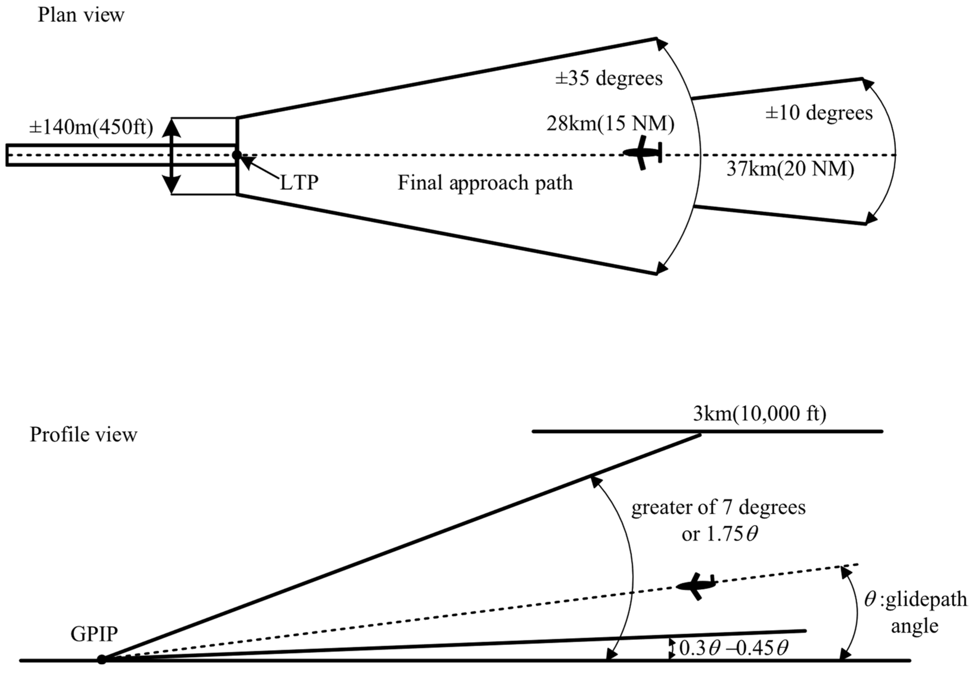
The effective isotropically radiated power (EIRP) shall provide for a horizontally polarized signal with a minimum field strength of 215 μV/m within the GBAS service volume. The minimum GBAS approach service volume [
20] is illustrated in
Figure 1. As shown, the service volume is characterized in both the lateral and vertical dimensions.
- (a)
laterally, beginning at 140 m on each side of the landing threshold point/fictitious threshold point (LTP/FTP) and projecting out ±35 degrees either side of the final approach path to 28 km (15 NM) and ±10 degrees either side of the final approach path to 37 km (20 NM); and
- (b)
vertically, within the lateral region, up to the greater of 7 degrees or 1.75 promulgated Glide Path Angle (GPA) above the horizontal with an origin at the glide path interception point (GPIP) to an upper bound of 3000 m height above threshold (HAT) and 0.45 GPA above the horizontal or to such lower angle, down to 0.30 GPA, as required, to safeguard the promulgated glide path intercept procedure. The lower bound is half the lowest decision height supported or 3.7 m, whichever is larger.
3. Electromagnetic Radiation Test of Maglev
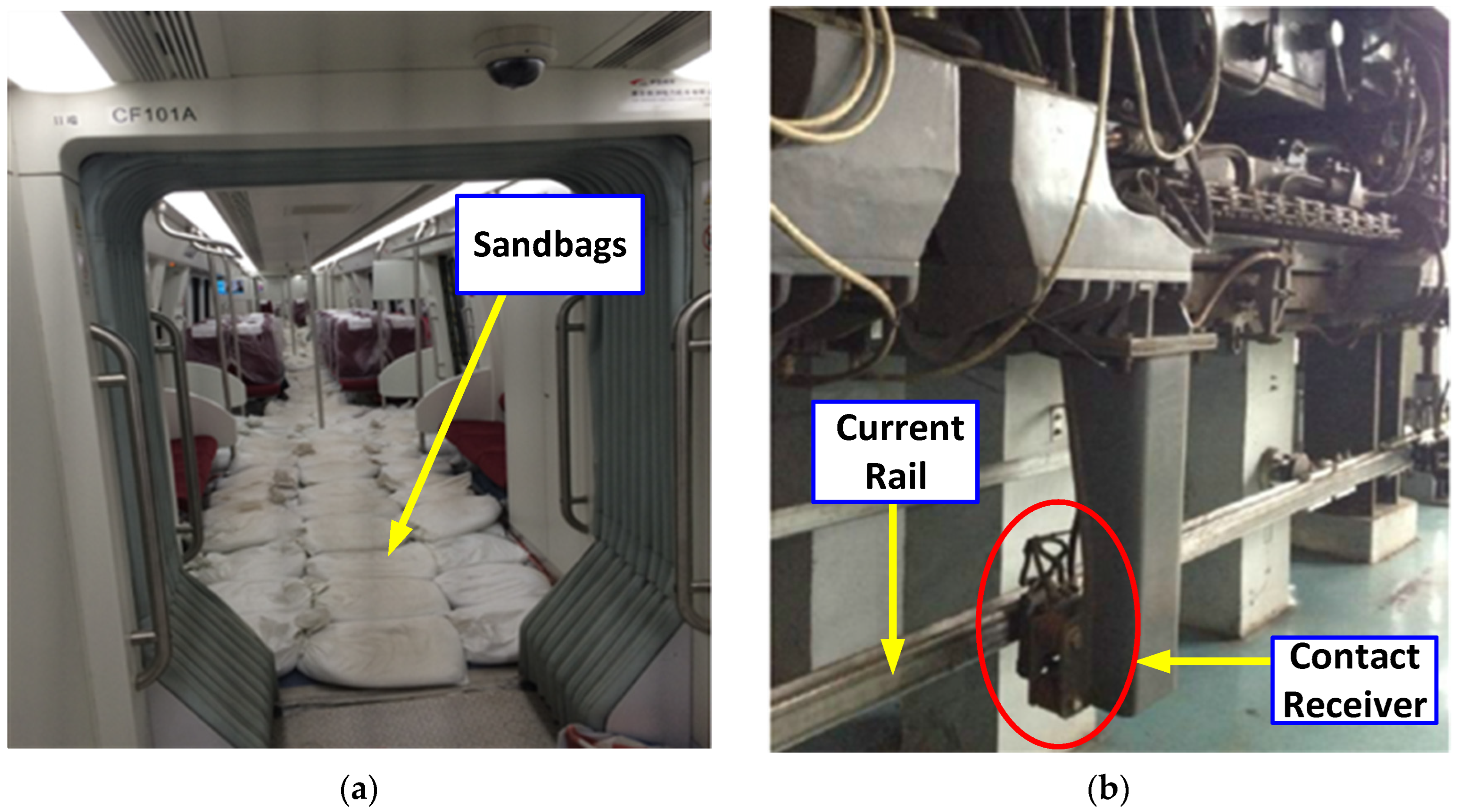
In this paper, medium-low speed maglev in trial operation is taken as the test object. Medium-low speed maglev trains were chosen because they have officially reported operational data and documented instances of integration with airports. These systems have been used in real-world intermodal settings where electromagnetic compatibility (EMC) with aviation navigation systems is a known issue, which makes them a good example for study. The maglev train is a three-section marshalling, and the load on the maglev train is shown in
Figure 2a. It illustrates the full-load test configuration adopted in the field measurements, where ballast (such as sandbags) is used to simulate actual passenger loads. This loading condition is critical for realistically reproducing the operational mechanical stress and dynamic response of the maglev current-collection system, thereby ensuring the validity of the electromagnetic emission data acquired under worst-case scenarios.
The traction network of medium-low speed maglev adopts contact backflow for power supply. The current receiver installed on the vehicle obtains electrical energy from the positive contact rail by sliding contact. The coordination relationship between the current receiver and the current rail is one of the most important relationships in the medium-low speed maglev train system. In the process of maglev train, as in
Figure 2b, the contact state between the current receiver and the current rail will shift and swing to different degrees with the change in different working conditions, and the off-line electric spark will occur at the moment of separation between the current receiver and the current rail. On both sides of the maglev line, the spark generates high frequency electromagnetic radiation.
The rationale for focusing on arc discharge at the current receiver/rail interface as the principal interference source is supported by both field measurements and prior studies. According to [
2,
25], the main electromagnetic interference (EMI) sources of medium-low speed maglev systems include: (i) AC magnetic fields from the linear motor, which are mainly distributed inside and near the train and attributed to low-frequency characteristics; (ii) DC magnetic fields from the suspended electromagnet, concentrated near the levitation air gap; and (iii) electromagnetic waves generated by collector shoe arcing, which are radiated at megahertz-level frequencies and can propagate through space to affect external devices. In particular, only the arc discharge is recognized as a significant source of broadband EMI in the VHF band (e.g., 108–118 MHz), directly relevant to the susceptibility of ground-based aviation navigation and communication equipment. Thus, the present experimental configuration and analysis focus on the worst-case electromagnetic emission scenarios associated with off-line arcing, while other subsystems are expected to contribute primarily to lower-frequency or narrowband interference and are not the dominant concern for VHF compatibility assessment.
Spectrum analyze N9340B (Keysight Technologies, Santa Rosa, CA, USA)was used for the test instrument, and R&S Biconical Antenna HK116 (Rohde & Schwarz GmbH & Co. KG, Munich, Germany) was used for the test antenna, as summarized in
Table 1.
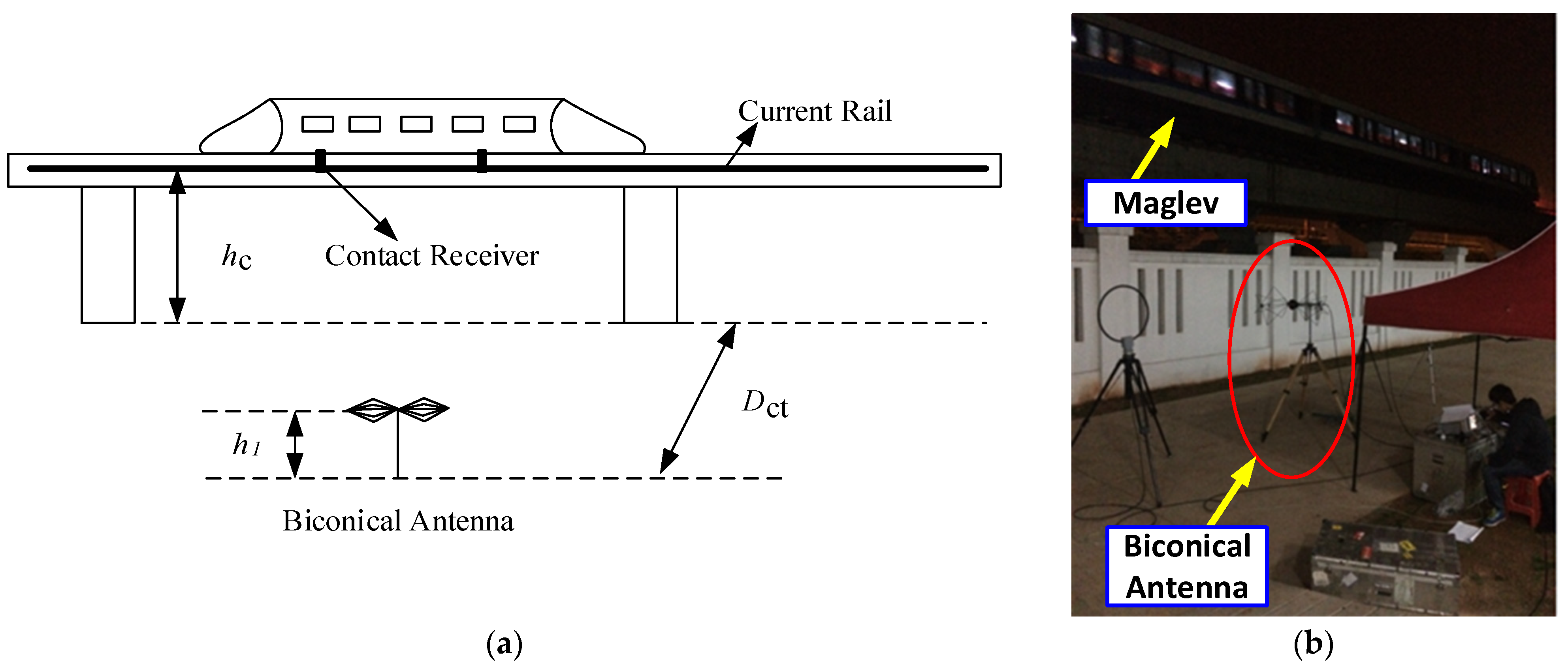
The schematic diagram of the test point layout is shown in
Figure 3a.
Dct is the vertical distance from the biconical antenna to the maglev line,
hc is the height of the maglev current rail,
h1 is the height of biconical antenna.
Dct = 17 m,
hc = 6 m,
h1 = 1.5 m.
Figure 3b displays an onsite snapshot of the measurement configuration, whereby the biconical antenna and corresponding testing apparatus were positioned near the functioning maglev line.
In this paper, the electric field strength (E-field) expressed in dBµV/m, is calculated as E(dBμV/m) = 20log10[E(V/m)/1(μV/m)]. The reported values are derived from receiver readings corrected by antenna factor and cable loss.
Figure 4 presents a comparative spectrum analysis of the electric field strength measured at the test site under three distinct maglev operational scenarios: maximum power deceleration, maximum power acceleration, and constant-speed travel. For each scenario, the electric field strength in the VHF band (108–118 MHz) is plotted as a function of frequency. The results reveal that during maximum power acceleration and deceleration, the maglev system produces a higher density of interference spikes across the spectrum compared to constant-speed operation. The peak electric field strengths are observed 57.76 dBμV/m at 113.4 MHz for deceleration, 56.41 dBμV/m at 110.8 MHz for acceleration, and 56.20 dBμV/m at 117.2 MHz for constant speed, respectively. Although the number of interference frequency points increases with acceleration and deceleration, the maximum electric field strength values among the three conditions are comparable, ranging from 56.20 to 57.76 dBμV/m. The combined spectrum figure offers a clear comparison, highlighting so that transitory operational states (acceleration and deceleration) result in more intricate and broadband interference characteristics in the VHF band, which are essential for subsequent electromagnetic compatibility study.
Comparing the spectrum curves of the merged spectrum figure, the acceleration or deceleration of the maglev at maximum power will produce more interference frequency points than the uniform speed. But the maximum electric field strength is not much different, ranging from 56.20 to 57.76 dBμV/m.
In this study, the maximum electric field strength was adopted as a conservative metric for worst-case electromagnetic compatibility (EMC) assessment, in accordance with established engineering practices and aviation measurement standards.
It should be noted that time–domain characteristics—such as pulse width, repetition rate, and duty cycle—are essential for evaluating intermittent interference and its impact on VDB data decoding. Although the primary analysis emphasized peak values to establish the upper bound of interference risk, limited oscilloscope observations during the measurement campaign confirmed the bursty and transient nature of arc events.
4. Signal Quality Analysis of VDB Under Maglev Arc Interference
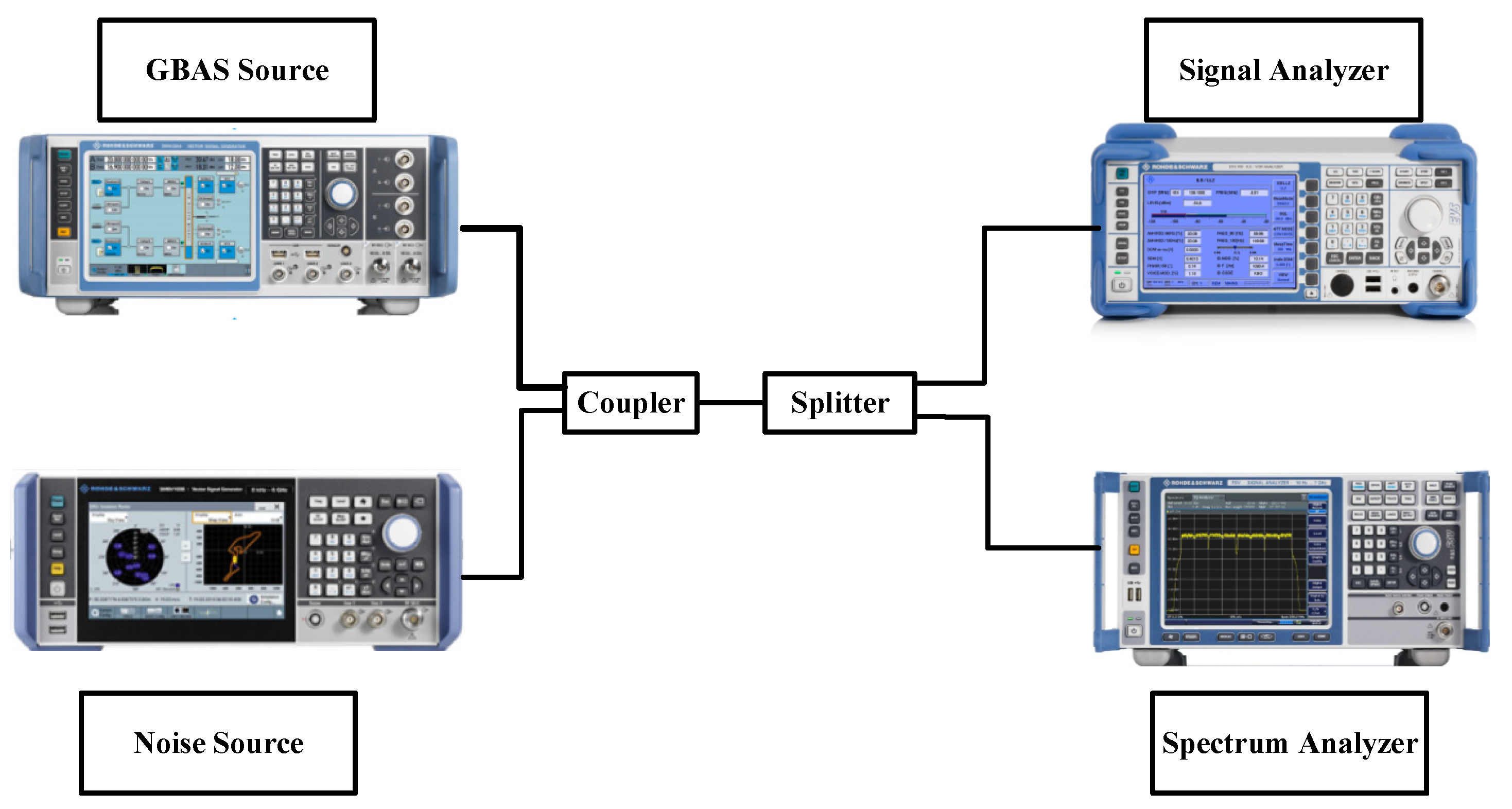
As illustrated in the test layout diagram, the experimental setup consists of two signal generators, a signal coupling and splitting unit, and two analysis instruments. The GBAS VDB signal is generated by the R&S SMBV100B vector signal generator, configured to transmit at a power level of −38.90 dBm. The electromagnetic interference signal, simulating magnetic levitation arc radiation, is generated by the R&S SMBV200B.
The outputs of both signal generators are combined via a directional coupler, allowing the interference signal to be injected into the main GBAS signal path. The combined signal is then passed through a splitter, which simultaneously feeds the signal to two measurement devices: an R&S EVS300 signal analyzer for evaluating the performance of the GBAS VDB signal, and an R&S spectrum analyzer for monitoring the spectral characteristics of the composite signal.
In addition, the selection of test locations strictly followed the requirements of GB6364-2013 [
26] and GB/T 24338-2018 [
27] (equivalent to IEC 62236-2018 [
28]) These standards ensure that the experimental setup and test positions comply with both aeronautical navigation EMC criteria and railway system emission regulations.
This configuration enables simultaneous observation of GBAS signal quality degradation under controlled interference levels, providing a reliable basis for assessing the susceptibility of VDB signals to electromagnetic radiation from magnetic levitation arc sources.
To evaluate the impact of broadband electromagnetic interference on the decoding performance of the GBAS VDB (Very High Frequency Data Broadcast) signal, a series of controlled signal-to-interference ratio (SIR) experiments were conducted. The transmission power of the GBAS VDB signal was fixed, while the interference power was varied to observe the effect on the demodulated message content, as illustrated in
Figure 5.
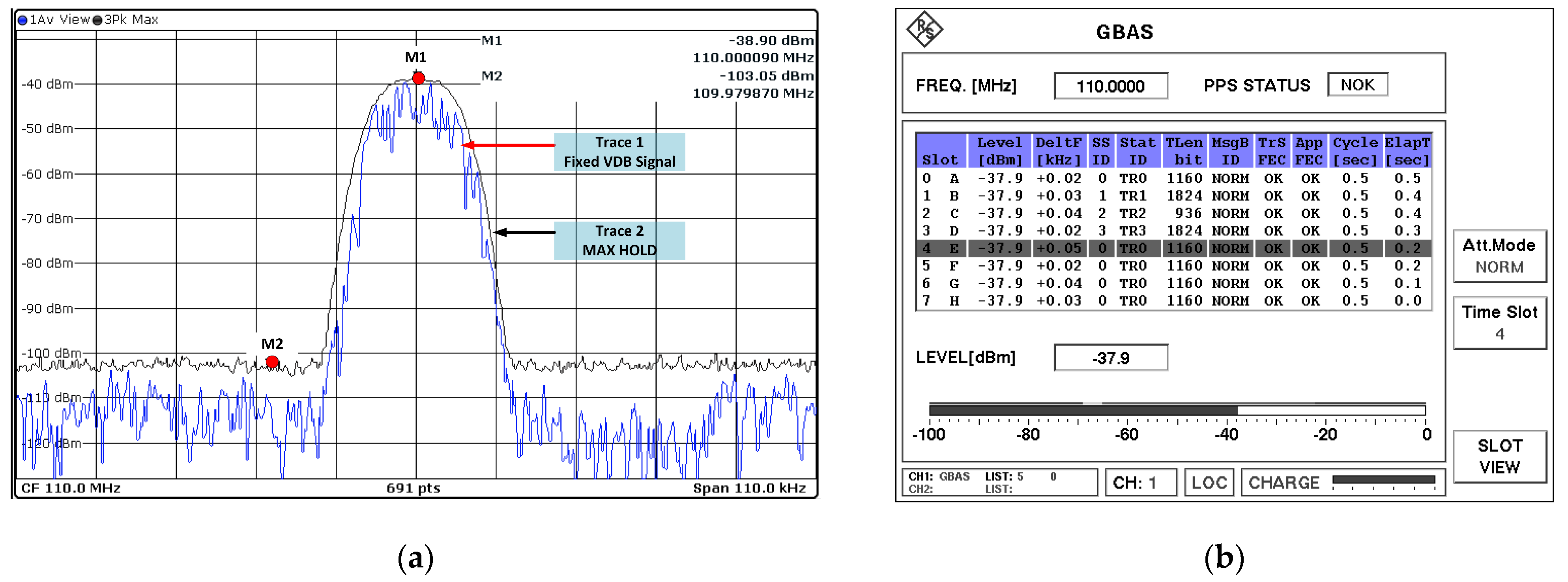
Under interference-free conditions, the GBAS VDB signal maintains excellent spectral purity and full decoding reliability.
Figure 6 demonstrates that both the spectrum measurement and decoding findings validate that, in the absence of interference, the VDB signal preserves its integrity and dependability, serving as a baseline for subsequent interference experiments.
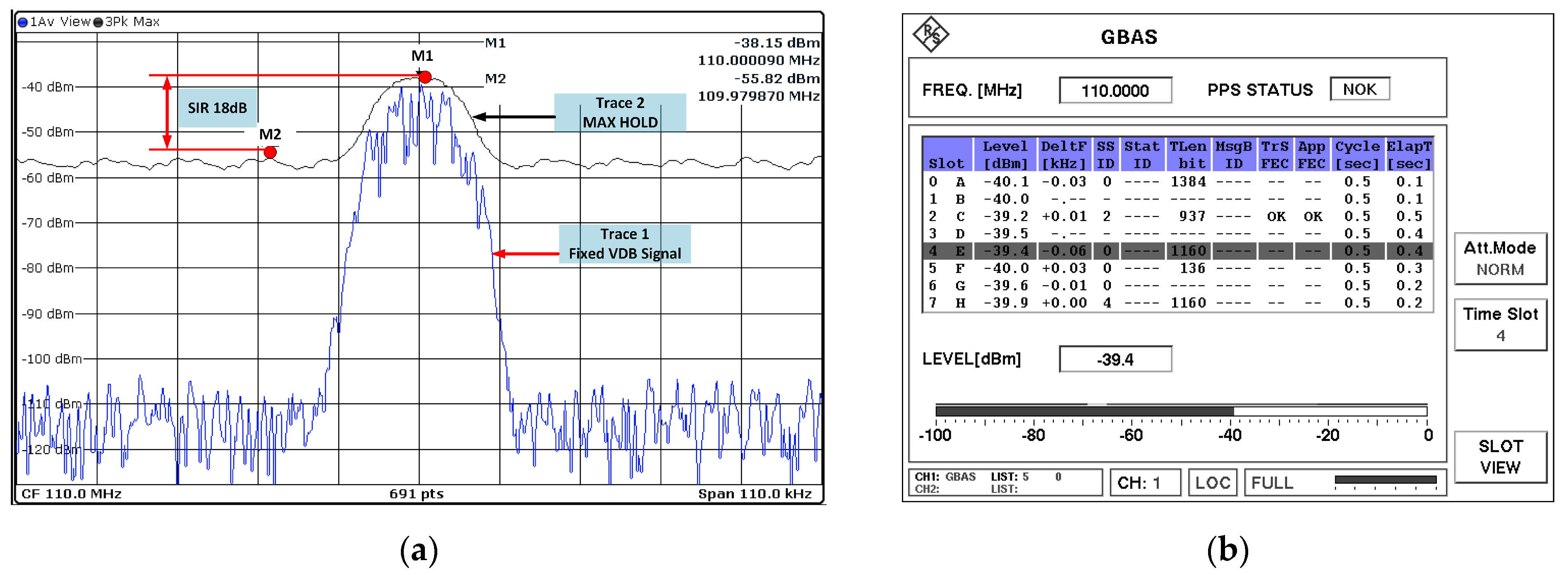
Figure 7 illustrates that when the signal-to-interference ratio (SIR) diminishes to 18 dB, the VDB decoding performance exhibits significant deterioration.
Figure 7a illustrates that the spectrum measurement reveals broadband interference at –55 dBm, elevating the noise floor and diminishing the effective SIR to 18 dB. The decoding results in
Figure 7b indicate that only a fraction of the time slots are successfully received, while the remainder are lost. This indicates that the signal is highly vulnerable to interference at this level, confirming the critical need for sufficient SIR margin in operational environments.
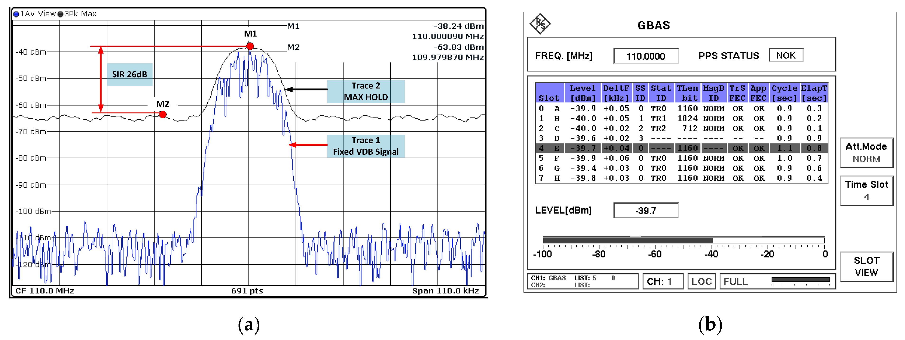
Figure 8 shows that when the SIR is 26 dB, the VDB signal can still be partially decoded, although it is less reliable than the baseline without interference.
Figure 8a shows the spectrum measurement. The broadband interference at –63 dBm boosts the noise floor and lowers the VDB signal’s effective margin.
Figure 8b displays the decoding result, which is similar. Even though some time slots are received correctly, there are some losses due to interference. This shows the area where the effects of interference go from being very small to very big. An SIR of roughly 26 dB seems to be a threshold, above which VDB decoding is mostly reliable and below which the chance of decoding errors goes up quickly.
Figure 9 shows that the VDB decoding performance is completely reliable when the SIR goes up to 29 dB.
Figure 9a shows the spectrum measurement, which shows that the applied –66 dBm broadband interference gives an effective SIR of 29 dB. In this situation, the VDB signal is still much stronger than the interference floor.
Figure 9b shows the decoding output, which shows that all eight time slots are received accurately and consistently without any loss. This result shows that the signal is quite strong at 29 dB SIR, which is a distinct difference from the partial decoding seen at 26 dB (
Figure 8) and the poor performance shown at 18 dB (
Figure 7).
Figure 7,
Figure 8 and
Figure 9 show the threshold behavior of VDB reception. The point at which decoding goes from being reliable to unreliable is 26 dB.
The experiment demonstrates that the GBAS VDB signal is highly sensitive to broadband electromagnetic interference. A minimum SIR of 26 dB is required to ensure error-free decoding of all time slots. Based on this observation, subsequent interference protection calculations and assessments are carried out with 26 dB as the protection threshold.
5. Interference Analysis
5.1. Radiation Field Intensity of Useful Signal Emitted by GBAS VDB Antenna on Approach Route
The VDB signal can reach more than one runway at once and send messages to more than one plane that is about to land. Therefore, it is necessary to consider the situation of the aircraft landing on the other side of the runway, or even the runway of the airport. At this situation, the VDB antenna is far away from the runway threshold, so the VDB signal will be weaker on the corresponding gliding path.
In
Figure 10, the relative position of VDB antenna 3000 m away from runway threshold, the vertical distance from GBAS VDB antenna to the runway centerline is
D (
D > 100 m), the horizontal distance between runway threshold and the aircraft’s projection on the ground is
x, the horizontal distance between GBAS VDB antenna and the ground projection point of the minimum radiation field strength along the approach path is
x0, the height of GBAS VDB antenna is
ha, the height of the aircraft from the ground is
h, the height of the minimum radiation field strength point along the approach path from the ground is
h0, the distance from GBAS VDB antenna to the aircraft is
rs, the pointing distance from GBAS VDB antenna to the ground projection point of the aircraft is
d, the pointing distance from GBAS VDB antenna to the ground projection point of the minimum radiation field strength along the approach path is
d0, the glide angle of the aircraft is
β.
According to the annex 10, from the LTP/FTP left and right sides of 140 m, based on the final approach path, expand outward to the distance LTP/FTP with an expansion angle of the 35°. The minimum radiation field strength of the horizontal polarization of GBAS VDB at 20 NM (37 km) is 215 μV/m.
Assuming that the transmitting power of GBAS VDB antenna is
Pr and the direction coefficient is
F, then the electric field intensity
E in the direction of maximum radiation is:
where
r is the distance from the observation point to the GBAS VDB antenna.
According to (1), the minimum radiation field strength of the VDB antenna at a distance of 20 NM (37 km) from LTP/FTP can be expressed as:
When the aircraft flies to a height of h from the ground, the radiation field strength of GBAS VDB antenna receives is:
From (2) and (3), GBAS VDB signal field intensity
ES that can be received by aircraft along the approach line under the minimum radiation field intensity specified in ICAO Annex 10:
where
,
.
The VDB antenna’s placement analysis in relation to runway thresholds was purposefully reduced to a static geometric configuration for this study. For the initial risk assessment, this was conducted in order to create a clear baseline and focus on the worst-case interference condition. Bounding models are frequently used in preliminary EMC evaluations to identify potential hazards, so this simplification is in line with standard engineering practice.
It is crucial to stress that the detailed EMC result may be impacted by more intricate elements, such as multiple interference angles, dynamic train movements, and the effects of terrain or structural shielding. By adding more geometric parameters and simulation steps, these elements—which indicate significant avenues for future research—can be integrated into the same framework.
5.2. Radiation Field Intensity of Useless Signal Emitted by Maglev Arc on Approach Route
When selecting a GBAS airport location, the site selection engineer must minimize the multipath effect on the ground and surrounding buildings. Therefore, the signal from GBAS VDB antenna to the aircraft can be regarded as propagating in free space without considering the impact of ground reflection. But for the arc electromagnetic radiation generated by maglev, the effect of ground reflection should be considered.
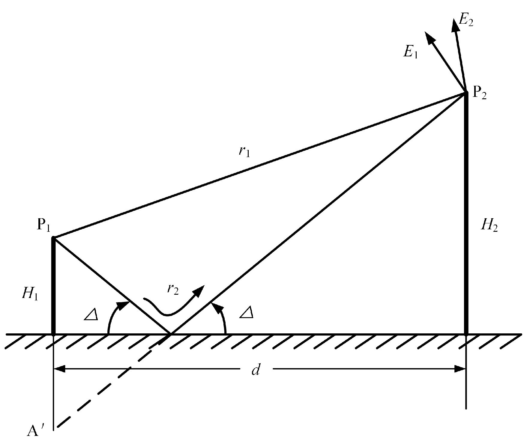
As shown in
Figure 11, the height of location P
1 where maglev arc occurs is
H1, and the height of the airborne VDB receiving antenna P
2 is
H2. The propagation path of the direct wave of electromagnetic radiation from the maglev arc is
r1, the propagation path of the ground reflected wave is
r2, and the projection angle between the maglev arc and the ground is
Δ.
The electric field amplitude generated by the direct maglev arc radiation along path
r1 at point P
2 is denoted as
E1, and the amplitude of the electric field generated by the reflected wave along path
r2 at point P
2 is denoted as
E2. Then the total field strength at P
2 is:
where Γ is the reflection coefficient of the ground.
For horizontally polarized waves, the reflection coefficient is about 1 at low projection angles, and the phase angle can almost be regarded as a constant 180°, that is to say, the reflection coefficient Γ can be regarded as −1.
(5) can be equivalent to follow:
where
,
is the transmitting power of maglev arc, and its direction coefficient is
F′.
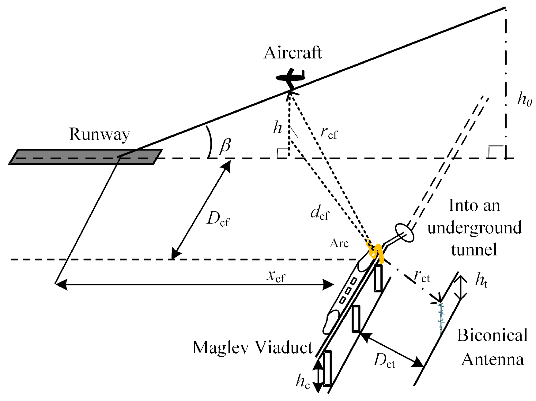
The positional relationship between the maglev viaduct and the runway is shown in
Figure 12. The maglev viaduct is perpendicular to the runway extension line, and enters the underground tunnel at a distance of
Dcf meters from the runway extension line.
Rcf is the distance from the maglev arc to the aircraft,
dcf is the distance from the maglev arc ground projection point to the aircraft ground projection point,
h is the height of the aircraft above the ground,
hc is the height of the maglev viaduct,
xcf is the horizontal distance from the maglev arc ground projection point to the aircraft ground projection point,
Dct is the vertical distance from the binocular antenna to the maglev line,
rct is the distance from the binocular antenna to the maglev arc, and
ht is the height of the binocular antenna.
Taking the ground reflection into the account, along the approach route, the electromagnetic radiation field strength
Eu of the maglev arc that the aircraft can receive is:
where
f is frequency of signal,
c is speed of light,
Ezc is the electric field intensity of the interference signal emitted by the maglev arc.
In the process of aircraft approach, the distance between the maglev arcing point and the aircraft and the distance between the GBAS VDB antenna and the aircraft are always dynamic changes, so the aircraft receives the useful signal emitted by the GBAS VDB antenna and the interference signal generated by the maglev arc is also changed.
5.3. Analysis of the Influence of Maglev Arc Electromagnetic Radiation on the Aircraft Landing Guided by GBAS VDB
According to the VDB protection rate, which is 26 dB, the difference between the useful signal and the interference signal must be greater than 26 dB to ensure that there is no interference to the aircraft landing. It should be noted that the minimum required SIR of 26 dB was determined under controlled laboratory conditions, where environmental uncertainties were minimized. In actual airport settings, other elements such multipath fading caused by structures and topography, ambient noise, and possible non-linear receiver effects may further diminish the effective decoding margin of the VDB signal. Consequently, the 26 dB threshold should be considered a baseline reference under optimal conditions, although the practical in-field requirement may exceed this level. Subsequent efforts will concentrate on testing and refining this threshold by systematic field observations and sophisticated simulations in intricate airport settings.
According to (4) and (9), the protection rate of VDB signal relative to maglev arc electromagnetic radiation is:
where
,
,
.
From
Figure 4,
Figure 5 and
Figure 6, the maximum radiation electromagnetic field strength of maglev arc
Ezc is 57.76 dBμV/m.
In the following calculation, the VDB antenna is arranged on the side adjacent to the airport runway as shown in
Figure 10, and maglev viaduct crosses vertically with the runway extension line as shown in
Figure 12. Take 113 MHz, which is the intermediate frequency of 113 MHz from 108 to 117.975 MHz as an example, and make its maximum radiation electric field intensity 57.76 dBμV/m. And other parameters are shown in
Table 2. There were two main reasons why 113 MHz was chosen as the frequency. First, the arc discharge energy from the collector shoe has a broadband characteristic that stays mostly the same across different operational situations. Second, 113 MHz is in the middle of the GBAS VDB operational band (108–118 MHz), and our field tests showed that the most broadband arc radiation happened close to this frequency. So, concentrating on 113 MHz gives you a useful point of reference for comparing arc radiation characteristics across the VDB band and makes airport EMC risk assessment more useful.
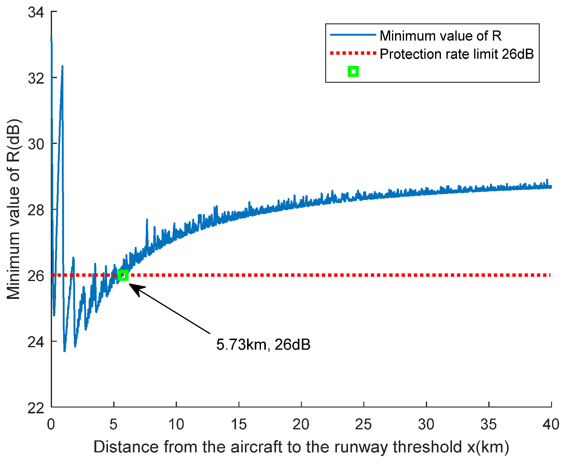
Figure 13 shows that the minimal value of the protection rate
R varies as a function of the aircraft’s horizontal distance
x from the runway threshold along the extended runway centerline. If the VDB antenna is 3000 m from the runway threshold, with
D = 200 m and
Dcf = 100 m, the protection rate drops below 26 dB within 5.73 km, which means there is a possibility of interference. The value of
R stays above 26 dB all the way to 5.73 km, which protects the VDB signal from maglev arc radiation.
6. Conclusions
This study methodically examined the electromagnetic compatibility (EMC) effects of medium-low speed maglev arc discharge on the Ground-Based Augmentation System (GBAS) VDB link, emphasizing the consequences for aircraft landing operations directed by the GBAS. A complete assessment framework was created to look at the dangers of interference from maglev arc radiation by combining field data, lab tests, and theoretical analysis.
The arc radiation was measured in the field during maximum acceleration, maximum deceleration, and constant-speed operation. The highest electric field strength was 57.76 dBµV/m. Laboratory tests showed that the integrity of GBAS VDB decoding drops a lot at a SIR of 18 dB, becomes somewhat unreliable at 26 dB, and stays fully reliable only above 26 dB. So, a SIR threshold of 26 dB is the practical protective standard for VDB signal integrity in operational planning.
Theoretical analysis revealed that with the VDB antenna situated 3000 m from the runway threshold and the maglev viaduct intersecting the runway extension line at 100 m from the centerline, a minimum horizontal separation of 5.73 km between the maglev arc source and the runway threshold is necessary to guarantee optimal VDB performance. This shows how important the arrangement of maglev infrastructure and the location of VDB antennas are for the safety of GBAS-guided airplane landings.
For this study, the analysis of the VDB antenna’s placement in relation to runway thresholds was intentionally simplified to a static geometric configuration. This was conducted for the first risk assessment to make a clear baseline and focus on the worst-case scenario for interference. This simplification is in line with standard engineering practice because bounding models are often used in early EMC evaluations to find possible hazards.
It is important to stress that more complex factors, like multiple interference angles, moving trains, and the effects of terrain or structural shielding, may affect the detailed EMC result. By incorporating additional geometric parameters and simulation steps, these elements—signifying substantial prospects for future research—can be assimilated into the same framework.
Because maglev systems are being quickly added to airports, the results show that careful planning of the electromagnetic environment and the site is needed to make sure that navigation signals can be received safely. This study concentrated on arc discharge as the primary interference mechanism; subsequent research will broaden the analysis to encompass additional operational scenarios, assess reflection and diffraction effects arising from intricate terrain and structures, and explore advanced interference mitigation techniques.
In conclusion, the results demonstrate that safeguarding GBAS VDB signals from maglev arc radiation is essential for the safety and dependability of aircraft landings. The results provided offer technical guidance for airport site selection, electromagnetic compatibility evaluation, and interference reduction measures, thereby facilitating the secure cohabitation of maglev transportation and aviation navigation systems.
Author Contributions
Conceptualization, X.L. and C.Z.; methodology, X.L.; software, X.L.; validation, X.L., C.Z., Y.T. (Yutao Tang) and Y.T. (Yifang Tan); formal analysis, X.L.; investigation, X.L.; resources, Y.T. (Yutao Tang); data curation, X.L.; writing—original draft preparation, X.L.; writing—review and editing, X.L.; visualization, X.L.; supervision, H.L.; project administration, H.L. All authors have read and agreed to the published version of the manuscript.
Funding
Funded by Open Fund Project of Flight Technology and Flight Safety Research Base (F2024KF17D), Fundamental Research Funds for the Central Universities (25CAFUC04008), Fundamental Research Funds for the Central Universities (24CAFUC03021), Open Fund Project of Sichuan Provincial Key Laboratory of Intelligent Low-Altitude Traffic Management (2025UASKLSP02).
Institutional Review Board Statement
Not applicable.
Informed Consent Statement
Not applicable.
Data Availability Statement
The data that support the findings of this research are available from the author, X.L., upon reasonable request.
Conflicts of Interest
The authors declare no conflicts of interest.
References
- Chen, Z.; Zhang, H.; Xu, X.; Ren, X.; Feng, D. Numerical study on dynamic characteristics of medium-low-speed maglev railway with novel structures for vehicle speed-up application. J. Vib. Control. 2025, 10775463251343661. [Google Scholar] [CrossRef]
- Huang, K.; Lin, G.; Liu, Z.; Zhu, F. Electromagnetic Disturbance Source Modeling Scheme and its Interference Estimation of Medium–Low-Speed Maglev Train Interior. Urban Rail Transit 2024, 10, 213–231. [Google Scholar]
- Ye, J.; Li, X.; Liang, F.; Li, Y.; Li, Q. Electromagnetic compatibility analysis of GBAS VDB by magnetic levitation arc. In Proceedings of the Seventh International Conference on Electromechanical Control Technology and Transportation (ICECTT 2022), Guangzhou, China, 27–29 May 2022; pp. 393–403. [Google Scholar]
- Tellini, B.; Macucci, M.; Giannetti, R.; Antonacci, G. Conducted and radiated interference measurements in the line-pantograph system. IEEE Trans. Instrum. Meas. 2002, 50, 1661–1664. [Google Scholar] [CrossRef]
- Wang, Y.; Liu, Z.; Mu, X.; Huang, K.; Wang, H.; Gao, S. An extended Habedank’s equation-based EMTP model of pantograph arcing considering pantograph-catenary interactions and train speeds. IEEE Trans. Power Deliv. 2015, 31, 1186–1194. [Google Scholar] [CrossRef]
- Wang, Y.; Liu, Z.; Mu, X.; Song, X.; Huang, K.; Deng, Y. Research on electromagnetic transient process in articulated split-phase insulator of high-speed railway considering viaduct’s electrical coupling. Int. Trans. Electr. Energy Syst. 2017, 27, e2376. [Google Scholar] [CrossRef]
- Huang, K.; Su, D. Extended pantograph–Catenary Arc modeling and an analysis of the vehicular-grounding electromagnetic transients of Electric multiple units. Energies 2024, 17, 1512. [Google Scholar] [CrossRef]
- Song, X.; Liu, Z. EMU-traction network modeling of high speed railway and electromagnetic transient influence considering secondary arcing of pantograph catenary. Electr. Power Autom. Equip. 2018, 38, 118–125. [Google Scholar]
- Huang, K.; Liu, Z.; Wang, Y.; Song, X.; Cheng, Y. Analysis on railcar’s body over-voltage distributional characteristics considering operating conditions of high-speed railway station. J. China Railw. Soc. 2016, 38, 38–45. [Google Scholar]
- Morant, A.; Wisten, Å.; Galar, D.; Kumar, U.; Niska, S. Railway EMI impact on train operation and environment. In Proceedings of the International Symposium on Electromagnetic Compatibility-EMC EUROPE, Rome, Italy, 17–21 September 2012; pp. 1–7. [Google Scholar]
- Midya, S.; Bormann, D.; Mazloom, Z.; Schutte, T.; Thottappillil, R. Conducted and radiated emission from pantograph arcing in AC traction system. In Proceedings of the 2009 IEEE Power & Energy Society General Meeting, Calgary, AB, Canada, 26–30 July 2009; pp. 1–8. [Google Scholar]
- Li, Y.; Zhang, J.; Fu, S.; Wu, D.; Xu, Q. Method of field measurement of electromagnetic environment of high speed maglev train. J. Phys. Conf. Ser. 2024, 2807, 012005. [Google Scholar] [CrossRef]
- Gou, J.; Zhu, F.; Zou, J.; Ye, J.; Li, H.; Wang, Y. Research on EMI of instrument landing system on aircraft caused by pantograph arc. J. China Railw. Soc. 2018, 40, 61–66. [Google Scholar]
- Xiao, Y.; Zhu, F.; Lu, N.; Wang, Z.; Zhuang, S. Radiation characteristics of pantograph-catenary arc and its influence on airport glide beacon. Acta Aeronaut. Astronaut. Sin. 2018, 39, 321252. [Google Scholar]
- Xiao, Y.; Zhu, F.; Lu, N.; Chen, Y.; Jiang, Q.; Yang, X. Analysis of Electromagnetic Emission of Pantograph-catenary Arc to VOR. In Proceedings of the 2020 IEEE International Symposium on Electromagnetic Compatibility & Signal/Power Integrity (EMCSI), Reno, NV, USA, 28 July–28 August 2020; pp. 654–658. [Google Scholar]
- Lu, H.; Zhang, Q. The EMI Analysis of aircraft approach landing by pantograph catenary arc of high-speed railway. Acta Aeronaut. Astronaut. Sin. 2020, 41, 220–225. [Google Scholar]
- Li, X.; Zhu, F.; Qiu, R.; Tang, Y. Research on influence of metro pantograph arc on airport navigation system. J. China Railw. Soc. 2018, 40, 97–102. [Google Scholar]
- Yu, K. Research on the principle of electromagnetic radiation in low and medium speed maglev traffic. J. Railway Eng. Soc. 2020, 37, 74–79. [Google Scholar]
- ICAO. ICAO Doc 9750-AN/963: Global Air Navigation Plan, 2016–2030; ICAO: Montréal, QC, Canada, 2016. [Google Scholar]
- ICAO. Aeronautical Telecommunications. In Annexes to the Convention on International Civil Aviation (ICAO); ICAO: Montréal, QC, Canada, 2016. [Google Scholar]
- Pullen, S.; Gao, G.; Tedeschi, C.; Warburton, J. The impact of uninformed RF interference on GBAS and potential mitigations. In Proceedings of the 2012 International Technical Meeting of The Institute of Navigation, Newport Beach, CA, USA, 17–21 September 2012; pp. 780–789. [Google Scholar]
- Datta-Barua, S.; Lee, J.; Pullen, S.; Luo, M.; Ene, A.; Qiu, D.; Zhang, G.; Enge, P. Ionospheric threat parameterization for local area global-positioning-system-based aircraft landing systems. J. Aircr. 2010, 47, 1141–1151. [Google Scholar] [CrossRef]
- Guenter, D.; Dennis, J. Initial operational experience with CAT I ground based augmentation system (GBAS). In Proceedings of the 2015 Integrated Communication, Navigation and Surveillance Conference (ICNS), Herndon, VA, USA, 21–23 April 2015; pp. S1-1–S1-14. [Google Scholar]
- Wang, Z.; Wang, S.; Zhu, Y.; Xin, P. Assessment of ionospheric gradient impacts on ground-based augmentation system (GBAS) data in Guangdong province, China. Sensors 2017, 17, 2313. [Google Scholar] [CrossRef]
- Zhang, H.; Zhang, J.; Deng, Z.; Wang, Q.; Li, X.; Tang, X.; Zhang, W. Study on electromagnetic radiation characteristics based on HTS maglev levitation test line. Electronics 2023, 12, 1776. [Google Scholar] [CrossRef]
- GB 6364-2013; Electromagnetic Environment Requirements for Aeronautical Radio Navigation Stations. Standardization Administration of China: Beijing, China, 2013.
- GB/T 24338-2018; Railway Applications—Electromagnetic Compatibility—Part 2: Emission of the Whole Railway System to the Outside World. Standardization Administration of China: Beijing, China, 2018.
- IEC 62236-2018; Railway Applications—Electromagnetic Compatibility—Part 2: Emission of the Whole Railway System to the Outside World. International Electrotechnical Commission: Geneva, Switzerland, 2018.
Figure 1.
Approach coverage volume.
Figure 1.
Approach coverage volume.
Figure 2.
Full-load operation test of maglev. (a) train interior ballasted with sandbags to emulate full-load operation during acceleration and deceleration; (b) current collector and positive contact rail on the vehicle side.
Figure 2.
Full-load operation test of maglev. (a) train interior ballasted with sandbags to emulate full-load operation during acceleration and deceleration; (b) current collector and positive contact rail on the vehicle side.
Figure 3.
Test Configuration and On-Site Measurement Setup for Maglev Arc Radiation: (a) Schematic diagram of the test; (b) On-site measurement setup.
Figure 3.
Test Configuration and On-Site Measurement Setup for Maglev Arc Radiation: (a) Schematic diagram of the test; (b) On-site measurement setup.
Figure 4.
Comparative Spectrum Analysis of Maglev Arc Radiation under Distinct Operational Modes.
Figure 4.
Comparative Spectrum Analysis of Maglev Arc Radiation under Distinct Operational Modes.
Figure 5.
Test Setup for GBAS VDB Signal Performance Evaluation under Electromagnetic Interference.
Figure 5.
Test Setup for GBAS VDB Signal Performance Evaluation under Electromagnetic Interference.
Figure 6.
Reference Measurement of GBAS VDB Signal without Interference. (a) Spectrum measurement of the GBAS VDB signal in the absence of interference; (b) Decoded VDB time-slot information with all messages correctly received under interference-free conditions.
Figure 6.
Reference Measurement of GBAS VDB Signal without Interference. (a) Spectrum measurement of the GBAS VDB signal in the absence of interference; (b) Decoded VDB time-slot information with all messages correctly received under interference-free conditions.
Figure 7.
GBAS VDB Signal Decoding Failure under Broadband Interference at an SIR of 18 dB. (a) Spectrum measurement with –55 dBm broadband interference applied, resulting in a signal-to-interference ratio of 18 dB; (b) Decoding output showing failure to retrieve valid time slot information for all eight slots under interference, where “-” indicates that the data are affected by interference and cannot be displayed by the signal analyzer.
Figure 8.
GBAS VDB Signal Decoding under Broadband Interference at an SIR of 26 dB. (a) Spectrum measurement with –63 dBm broadband interference applied, resulting in a signal-to-interference ratio of 26 dB; (b) Decoding output showing partial success, with some time slots successfully received while others are lost due to interference, where “-” indicates that the data are affected by interference and cannot be displayed by the signal analyzer.
Figure 9.
GBAS VDB Signal Decoding under Broadband Interference at an SIR of 29 dB. (a) Spectrum measurement with –66 dBm broadband interference applied, resulting in a signal-to-interference ratio of 29 dB; (b) Decoding output showing full and correct reception of all eight VDB time slots, indicating robust signal integrity under this interference condition, where “-” indicates that the data are affected by interference and cannot be displayed by the signal analyzer.
Figure 10.
VDB antenna located 3000 m from runway threshold.
Figure 10.
VDB antenna located 3000 m from runway threshold.
Figure 11.
Reflection of maglev arc on the ground.
Figure 11.
Reflection of maglev arc on the ground.
Figure 12.
Maglev and runway relative position diagram.
Figure 12.
Maglev and runway relative position diagram.
Figure 13.
Minimum value of the protection rate R versus aircraft distance from the runway threshold, with the VDB antenna located 3000 m from the threshold, lateral offset D = 200 m, and maglev entry distance Dcf = 100 m. The critical separation of 5.73 km corresponds to the 26 dB protection threshold.
Table 1.
Test instruments and frequency ranges.
Table 1.
Test instruments and frequency ranges.
| Device | Model | Frequency Range |
|---|
| Spectrum analyze | N9340B | 100 kHz–3 GHz |
| Biconical Antenna | HK116 | 20~300 MHz |
Table 2.
Input parameters for calculating the electric field strength and protection ratio of Maglev arc electromagnetic radiation at the VDB receiving antenna.
Table 2.
Input parameters for calculating the electric field strength and protection ratio of Maglev arc electromagnetic radiation at the VDB receiving antenna.
| Symbol | Value | Symbol | Value |
|---|
| x0 [km] | 37 | Ezc [dBμV/m] | 57.76 |
| D [m] | 200 | hc [m] | 6 |
| ha [m] | 13 | ht [m] | 1.5 |
| F [MHz] | 113 | Dct [m] | 17 |
| C [m/s] | 3 × 10⁸ | Β [°] | 3 |
| Disclaimer/Publisher’s Note: The statements, opinions and data contained in all publications are solely those of the individual author(s) and contributor(s) and not of MDPI and/or the editor(s). MDPI and/or the editor(s) disclaim responsibility for any injury to people or property resulting from any ideas, methods, instructions or products referred to in the content. |
© 2025 by the authors. Licensee MDPI, Basel, Switzerland. This article is an open access article distributed under the terms and conditions of the Creative Commons Attribution (CC BY) license (https://creativecommons.org/licenses/by/4.0/).
