Article

A Polydimethylsiloxane (PDMS) Transparent Fresnel Zone Lens Antenna at Ku-Band for Satellite Communication

1
Department of Civil, Environmental and Mechanical Engineering—DICAM, University of Trento, 38123 Trento, Italy
2
Department of Electronics and Communication Engineering, Centre for Flexible Electronics and Advanced Materials, Amrita Vishwa Vidyapeetham, Amritapuri 690525, India
3
Fondazione Bruno Kessler (FBK), Via Sommarive 18, 38123 Trento, Italy
*
Author to whom correspondence should be addressed.
Electronics 2025, 14(19), 3766; https://doi.org/10.3390/electronics14193766
Submission received: 27 August 2025 / Revised: 21 September 2025 / Accepted: 23 September 2025 / Published: 24 September 2025
(This article belongs to the Section Microwave and Wireless Communications)

Abstract

This work presents the design of a transparent Fresnel-zone lens antenna fabricated from Polydimethylsiloxane, also known as PDMS or dimethicone, a polymer widely used for manufacturing and prototyping microfluidic chips. The antenna operates in the K u band at 15 GHz. Specifically, a 3D-printed polylactic acid (PLA) mold is created and filled with PDMS to obtain the lens structure. The PLA mold can be used multiple times to produce different lens prototypes. An antenna prototype has been designed, fabricated, and assessed numerically and experimentally, demonstrating the capabilities and potential of the proposed design and production methodology.

1. Introduction

Communication antennas usually require high gain and a well-focused beam pattern [1]. The most diffused conventional electromagnetic radiators are reflectors or lens antennas. Reflector antennas [2] use a small feeder placed in the focus of a shaped electromagnetic metallic mirror. An alternative to metallic mirrors is the use of electromagnetic lens antennas [3] usually fabricated with dielectric materials. The radiation pattern of these antennas is mainly controlled by the reflector or lens shapes. Other interesting applicative scenarios are reported in [4,5,6]. Despite the high performances provided by reflectors and lens antennae, they are bulky and mechanically weak, and their dimensions are usually not compatible with small satellites. Other important disadvantages of these antennas include the high production cost, and installation that are undesirable, especially for large productions and commercial products, such as broadcasting satellite applications. New promising electromagnetic radiators called Fresnel zone antenna, demonstrated their effectiveness particularly for the consumer telecommunication market [7]. Fresnel zone antennas belong to the family of reflectors and lens antennas, but the beam pattern and the focusing effects are controlled through suitable phase shifts by acting on the lens surfaces and zones to their shapes [8]. There are numerous advantages of Fresnel antennas to conventional reflector or lens antennas. In particular these antennas, beyond the high gain, focused main beam, and low side lobe levels (SSLs) are cheaper, mechanically robust, and easy to install to conventional antennas. Moreover, Fresnel antennas can be made flat to improve their compactness [9,10,11,12,13]. In recent years, different research groups developed different efficient antenna prototypes. Additive technologies strongly simplify the development of lens prototypes [14,15,16,17]; however, it is quite difficult to find materials with a suitable dielectric permittivity. To overcome this problem in [13], an array of fractal antennas were integrated with a grooved Fresnel lens. In [18], a Fresnel lens based on annular dielectric material of different electric permittivity was proposed for the X band at 10 GHz, while in [19], to overcome the difficulty of finding suitable dielectric materials with the correct dielectric permittivity, a hybrid design including both grooved and perforated features, aimed at controlling the phase shift, has been considered. Despite the success of these attempts, numerous problems remain. In particular, additive technologies are quite flexible, but they require a lot of time and they are not suitable for large production. The obtained lens prototypes are mechanically fragile due to the rigidity of the material. The use of grooved or material perforation techniques is not sufficiently accurate and they require a specific calibration phase [20,21]. Some applications require the development of transparent lenses and this further reduces the material availability [16,22]. In this work, we propose an easy fabrication process for the design of a transparent Fresnel-zone lens antenna fabricated in a polydimethylsiloxane polymer (PDMS). The PDMS is a polymer characterized by good mechanical properties. In particular, PDMS is transparent and flexible; in its liquid form, PDMS can be easily cast into a suitable mold. Once solidified, the lens prototype can be extracted from the mold, which can be reused several times. Making the production process easy and cheap. Moreover, PDMS is significantly robust to high temperatures; these characteristics make it particularly suitable in scenarios characterized by vibrations, mechanical stress, and high temperatures, such as the spatial environment. A lens antenna prototype working in the K u band at 15 GHz has been designed, fabricated numerically, and experimentally assessed. The obtained results are quite satisfactory and promising. The work is organized as follows: In Section 2, the mathematical formulation is presented. Section 3 reports the description of the antenna prototype, and to the numerical and experimental assessment. Finally, Section 4 draws the conclusions.

2. Mathematical Formulation

The Fresen zone lens (FZLs) are designed to work in the K u band at f = 15   GHz . A single Fresnel zone has been considered and the following equation provides the outer diameter for a planar lens with M full-wave circular zones [10]:
D = 2 2 M λ 0 F + ( M λ 0 ) 2
where λ 0 is the wavelength, F is the focal length of the lens, and M is the number of considered full-wave circular zones. For this design, a single Fresnel zone M = 1 has been considered. The full-wave zone is divided into N subzones, where N is an even number N = 2 , 4 , 6 , 8 , . . . . which represents the phase correction. In particular, the phase at every n-th subzone differs from the adjacent sub-zone phase by ± 2 π N radians. For N = 2 , the subzones are equal to the half-wave Fresnel zones, for N = 4 the lens becomes a quarter-wave phase correcting lens, and so on for N = 6 , 8 , etc. In this work, N has been set to N = 8 . The outer radius of the n-th subzone is provided from the following relation [11]:
S n = 2 n F λ 0 N + n λ N 2 n = 1 , 2 , , N
The step size t s is the same for all the annular areas and it can be estimated by using the following formula:
t s = λ 0 · ε r N · ε r 1 .
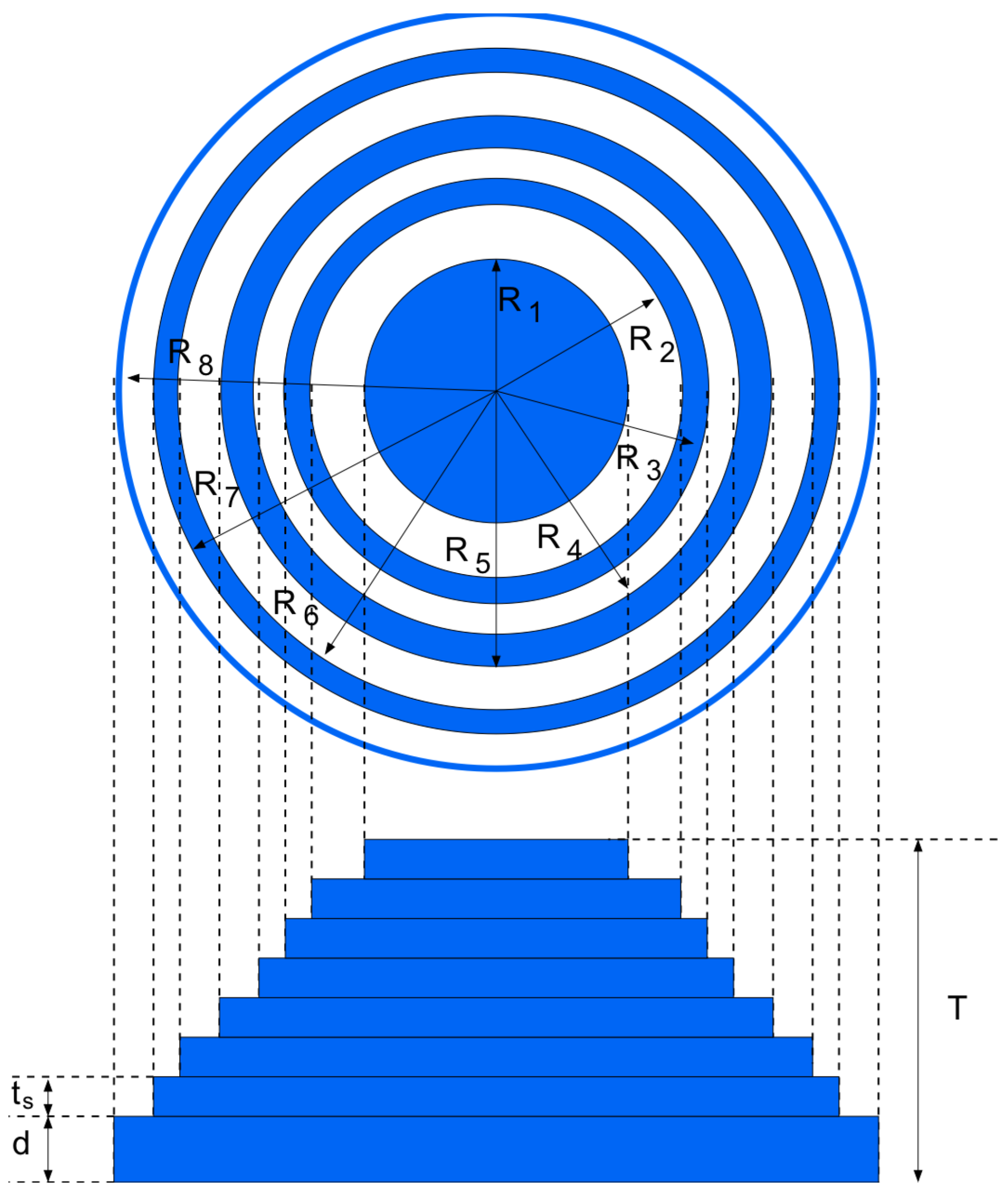
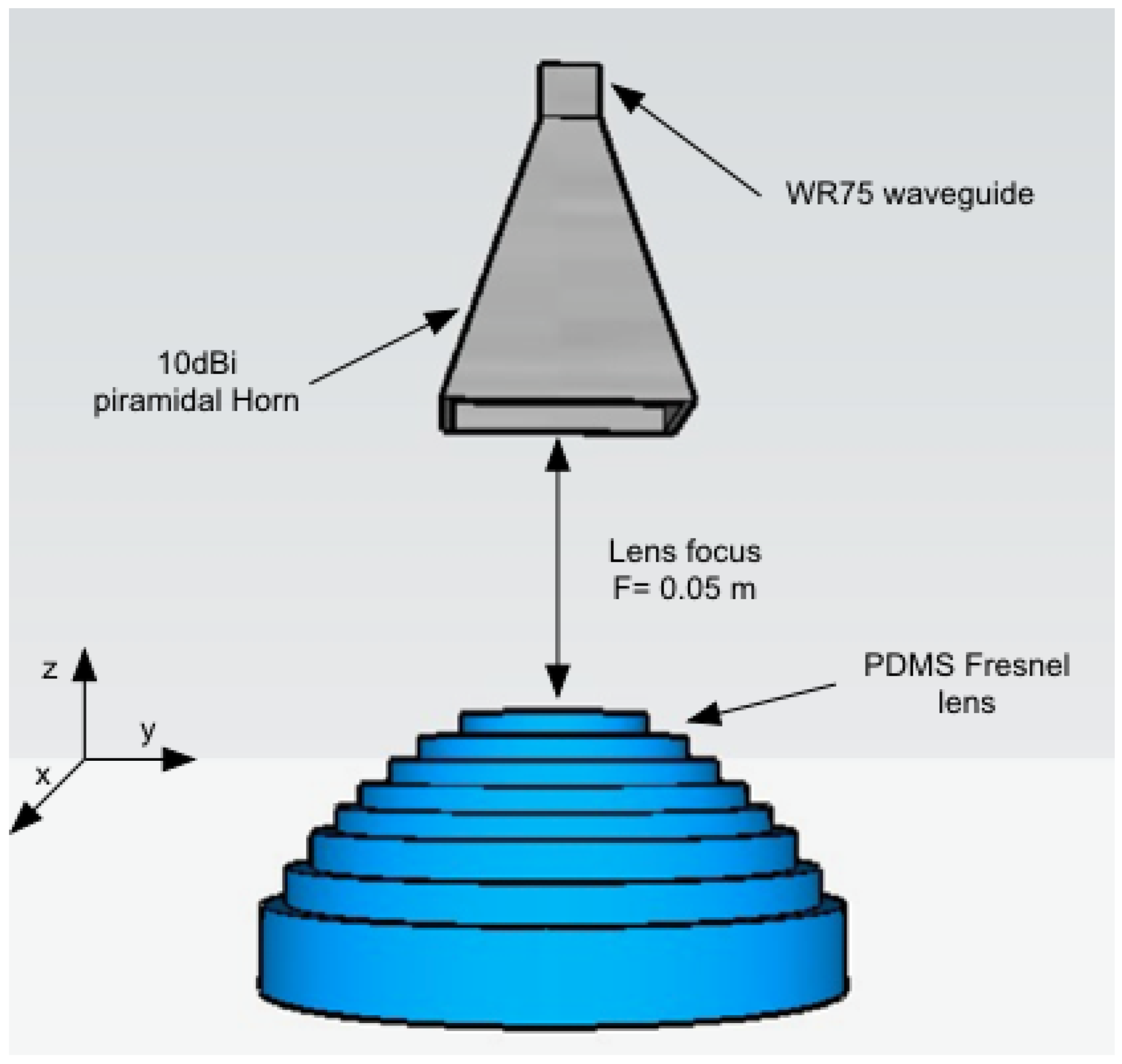
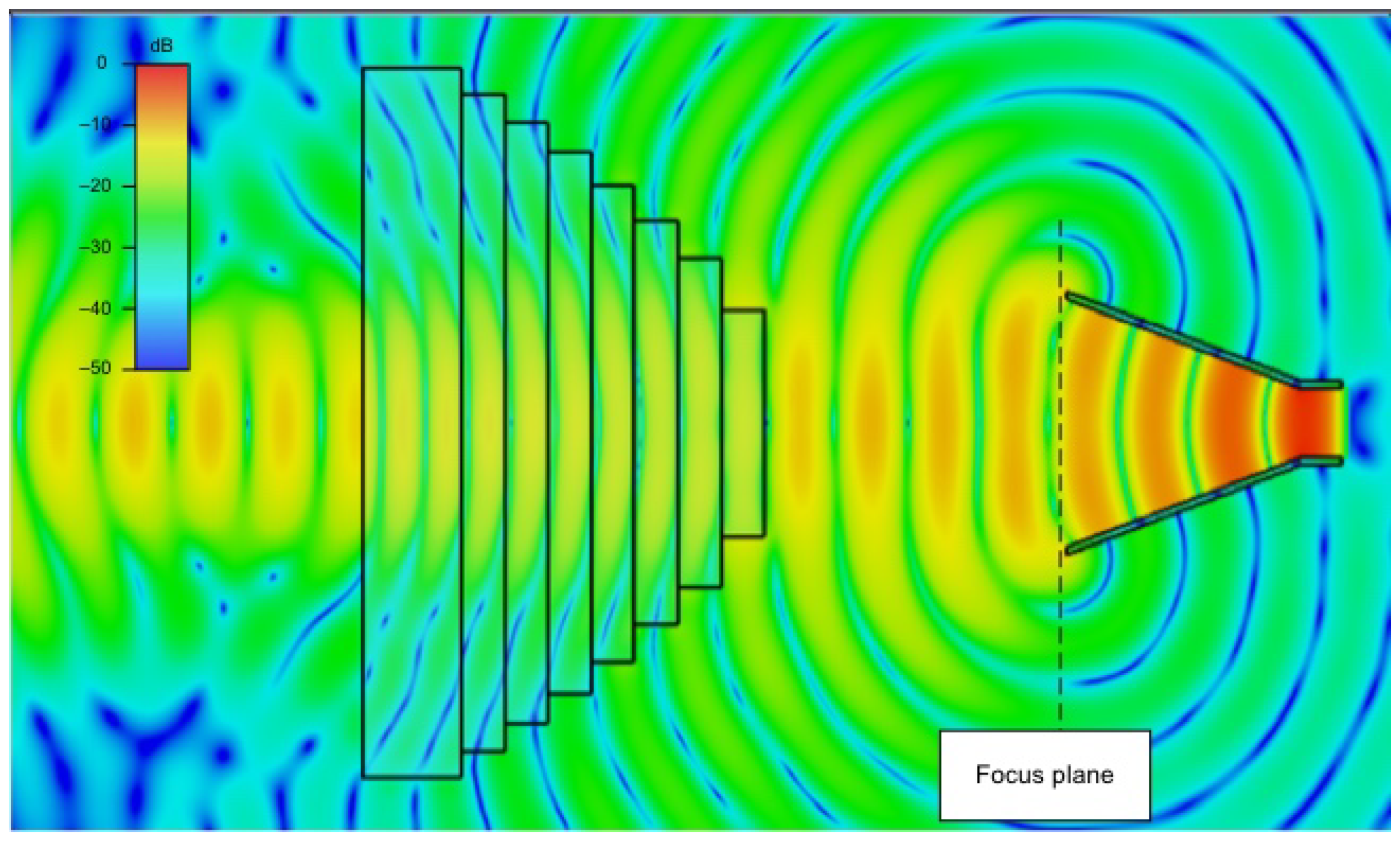
The lens is made with PDMS material characterized by its dielectric characteristics, which are presented in Figure 1 and show good agreement with the values, as reported in [23]. The lens diameter D = 9.8 cm and the lens focus F = 5 cm leads to F / D = 0.51 . To achieve a good impedance matching, the thickness of the FZL substrate is set to a quarter wavelength [9] d = 0.82 cm. The structure and parameters of the FZL are shown in Figure 2, while the values of each geometrical parameter are reported in Table 1. The CAD of the antenna is reported in Figure 3. It consists of a horn antenna used as a feeder placed in the lens focus and the PDMS lens. The structure was numerically assessed with a commercial numerical simulator CST. The horn antenna was used as a feeder and its phase center was placed in the lens focus. Concerning the simulation parameters, the horn was designed considering the antenna CAD, and a waveguide port was used as the excitation. The lens material was introduced considering the PDMS losses in the considered frequency range. A Hexaedral FIT adaptive mesh, with a frequency range from 14 GHz to 16 GHz with steps of 100 MHz, was used. A time domain solver, under adsorbent boundary conditions, was placed half a wavelength away from the antenna structure and used for the simulation. The electric field distribution along the YZ plane is reported in Figure 4. As it can be noticed the spherical waves emitted from the horn it is converted to plane waves by the lens. Thus, the radiating characteristics are improved, in particular, the gain has been improved from 18 dBi to 21 dBi and the width of half power beam width (HPBW) is strongly reduced from 30 up to 18 degrees confirming the lens’s effectiveness.

3. Antenna Prototype

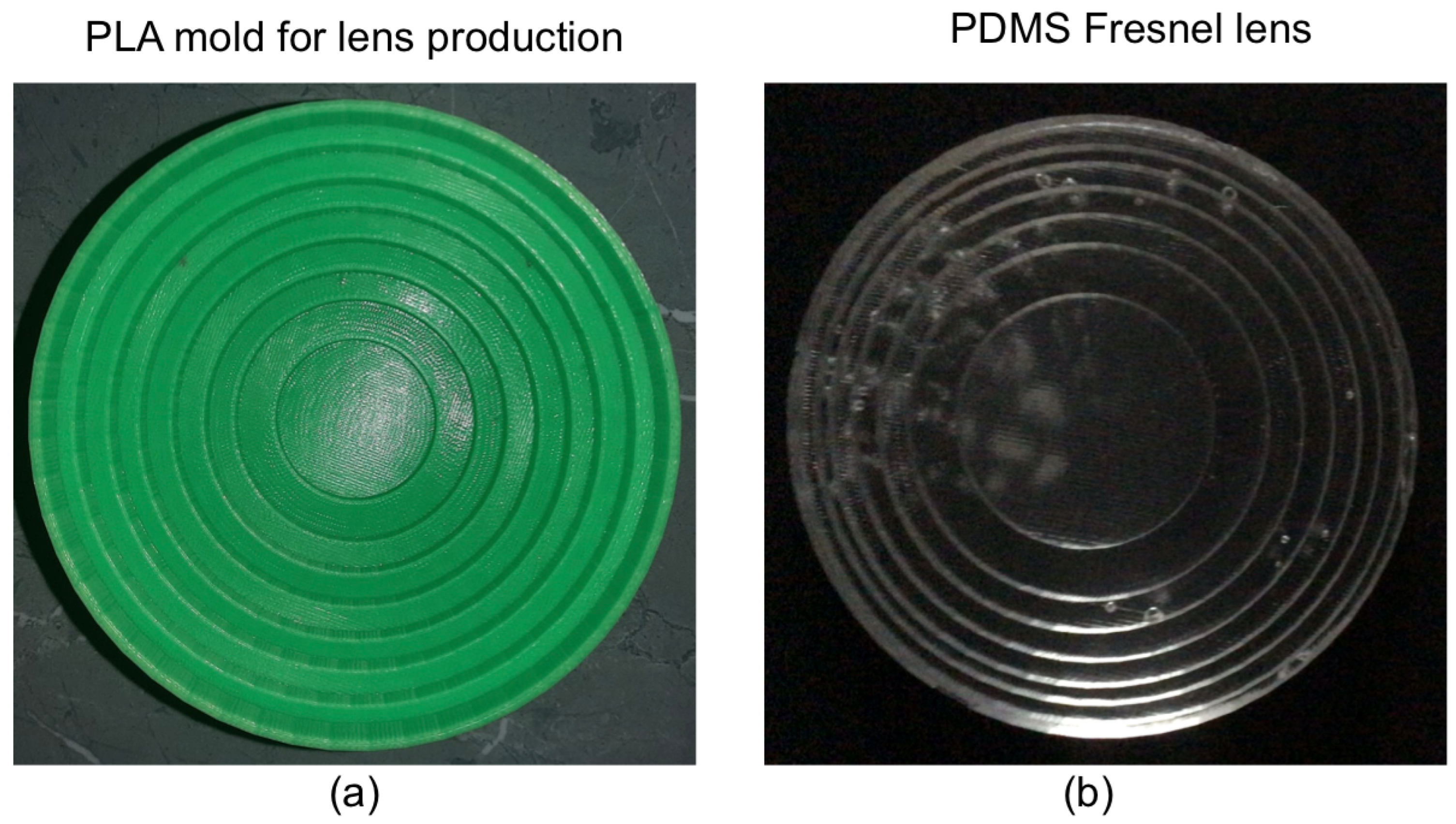
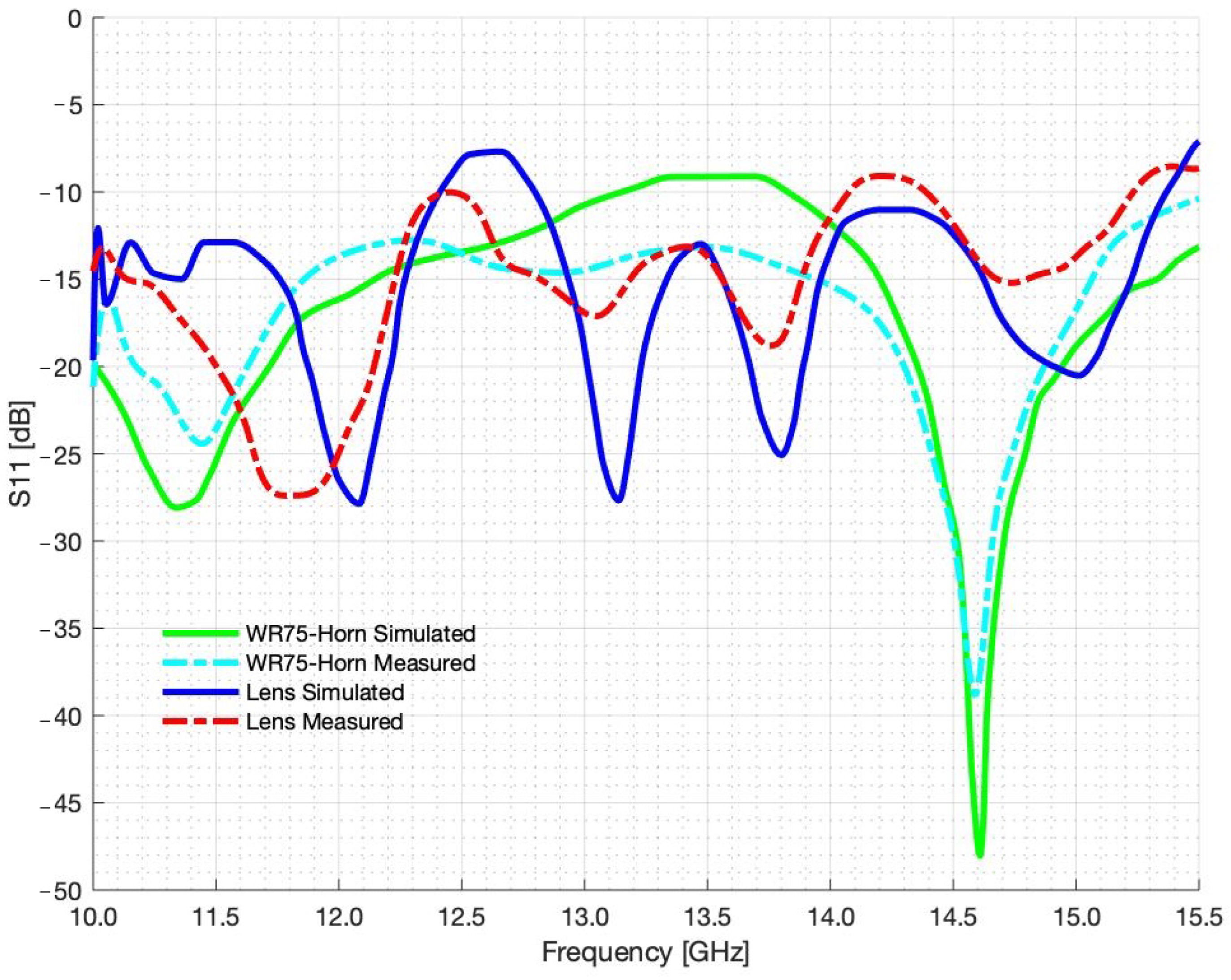
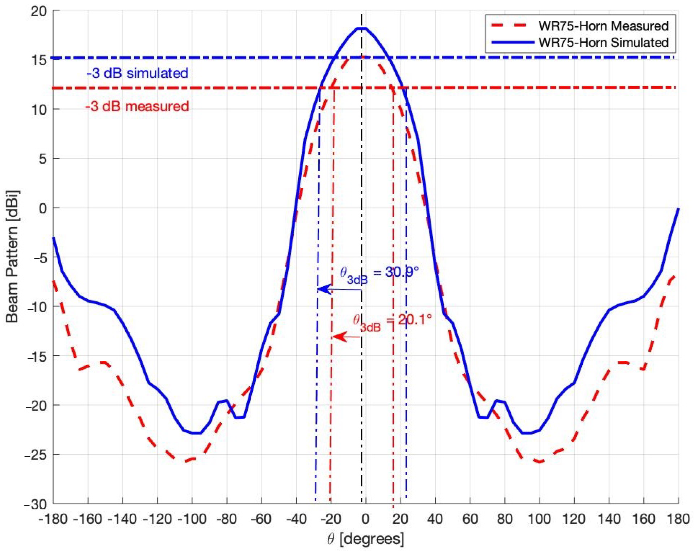
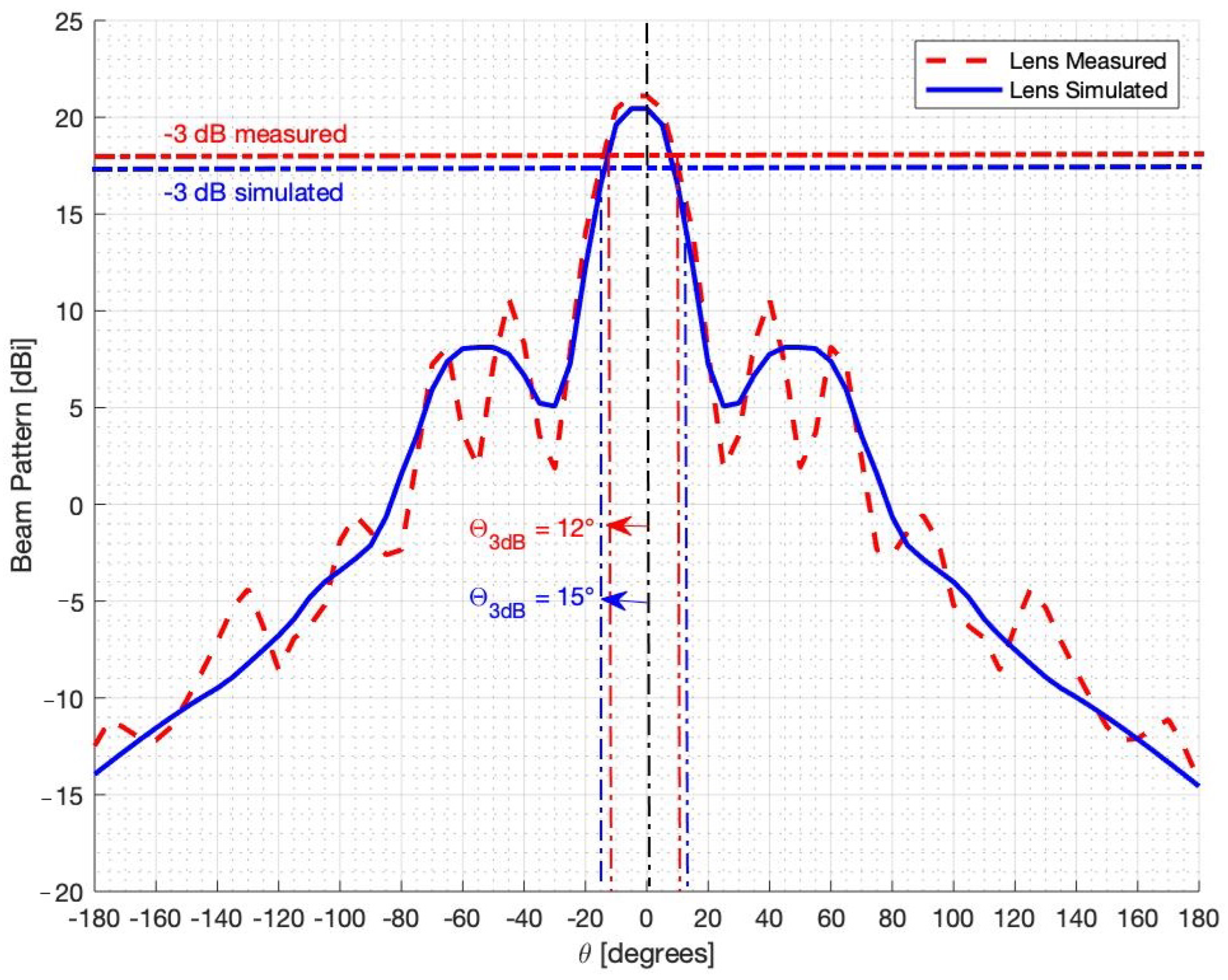
In this section, the fabrication procedure of the lens antenna will be detailed. Starting from the geometrical parameters reported in Table 1, a negative mold of the lens was designed using additive technology. In particular, a Flashforge 3D printer and a PLA filament was used to fabricate the mold. The liquid PDMS was prepared by mixing the two components of a SYLGARD 184 Silicone Elastomer Kit in the recommended 1:10 proportion into a plastic container. After stirring vigorously for about 10 min to reduce the bubbles, the liquid PDMS was cast into the mold and left under vacuum for 30 min to eliminate the remaining bubbles. After that, the mold and the PDMS were baked at 60 °C for 4 h to complete the solidification. The mold was left to cool overnight and then the PDMS was removed from the mold. After the solidification of the PDMS, the lens was removed. A photo of the PLA mold and the PDMS lens is reported in Figure 5. The PLA mold can be reused to fabricate other lenses making the fabrication process easy, fast, and cheap. It is worth noting that the fabrication process does not damage the PLA mold, which presents a surface roughness below 0.2 mm. This guarantees the reproducibility of the lens without affecting the radiative lens performance since the surface roughness is well below the wavelength. The radiative performances of the proposed prototype are similar to those obtained with other fabrication technologies. However, the use of PDMS material and the proposed fabrication methodologies offer indisputable advantages with respect to the other fabrication methodologies, as reported in Table 2. A WR-75 pyramidal horn, namely PEWAN075-10ELFN (Pasternack company, Irvine, CA, USA), was used as a feeder and placed in the lens focus. Then, the antenna prototype was arranged inside an anechoic chamber to experimentally assess the radiation characteristics. First, the return loss S 11 at the feeder port was measured using a vectorial network analyzer to verify the effects of the PDMS lens. The results are shown in Figure 6. In particular, in Figure 6, the measured (dotted lines) and simulated (continuous lines) S 11 , with and without the lens, are compared. As can be seen, the effects of the lens are quite evident but the S 11 remains below −10 dB, especially at F = 15 GHz where the return loss is about 15   dB . In the next measurements, the antenna beam pattern and gain are estimated. For the sake of comparison, also in this case, numerical and experimental data, with and without the lens have been compared. The beam pattern was collected along the E-plane with an angular step of 1 degree. The measurements are reported in Figure 7. In particular, Figure 7 reports the comparisons of the measured and simulated beam patterns of the feeder without the PDMS lens. As shown, the agreement between numerical and simulated data are quite good. The feeder presents a main beam aperture of about 20 degrees and a gain of 15 dBi (confirmed by the antenna datasheet). The measured values are better than the simulated ones. Then, the PDMS lens were introduced. Figure 8 reports the comparisons of the measured and simulated beam patterns of the lens antenna. Also, in this case, the agreement the measured and simulated data are very satisfactory. The improvements produced by the introduction of the PDMS lens are evident. The gain has been improved by about 5 dB and the main beam aperture was strongly reduced by about 17 degrees as can be noticed by comparing the results of Figure 7 and Figure 8. The potential sources of experimental errors could be identified with the incorrect positioning of the feeding and the possible misalignment of the lens. However, considering that we are working at a centimetric wavelength and that the incorrect positioning and alignments due to the considered mechanical pedestal are limited to a few mm, well below the wavelength of the considered working wavelength, as confirmed by the limited errors and the good agreement between experimental and numerical data. Thanks to the material’s elastomeric properties, the lens can withstand strong mechanical stresses such as impacts and vibrations, unlike rigid materials such as PLA or other polymers commonly used in additive technology. This makes the PDMS material particularly suitable for satellite applications where mechanical stresses, especially during the launch, are quite common and strong.

4. Conclusions

A Fresnel zone lens antenna fabricated in PDMS material has been proposed in this letter. The properties of PDMS make fast and cheap the lens fabrication procedure, with respect to addictive manufacturing technologies based on 3D printers or CNC, which require a lot of time and cannot be used for large production. Moreover, PDMS is transparent, and thanks to its flexibility it is able to absorb strong mechanical stresses such as strong vibrations, impacts, and bending, capable for damaging other rigid materials such as PLA or other dielectric materials. An antenna prototype has been designed, fabricated, numerically, and experimentally assessed. The obtained results were quite satisfactory and they demonstrated the potentialities of such material.

Author Contributions

Conceptualization, M.D., S.M. and V.M.; software, I.D.C.; validation, G.M., V.M., S.M. and M.D.; writing—original draft preparation, M.D., S.M. and V.M.; writing—review and editing; supervision, M.D., S.M. and V.M. All authors have read and agreed to the published version of the manuscript.

Funding

This research received no external funding.

Data Availability Statement

Data are contained within the article.

Conflicts of Interest

The authors declare no conflicts of interest.

References

  1. Kitsuregawa, T. (Ed.) Advanced Technology in Satellite Communication Antennas: Electrical and Mechanical Design; Artech House: Norwood, MA, USA, 1990. [Google Scholar]
  2. Sharma, S.K.; Rao, S.; Shafai, L. (Eds.) Handbook of Reflector Antennas and Feed Systems: Volume 1: Theory and Design of Reflectors; Artech House: Norwood, MA, USA, 2013. [Google Scholar]
  3. Thornton, J.; Huang, K.-C. Modern Lens Antennas for Communications Engineering-MAJ (1. Aufl); Wiley-IEEE Press: Hoboken, NJ, USA, 2012. [Google Scholar]
  4. Biswas, S. Dual-Polarized Antenna Feed Matrix Design for Multibeam Lens Antenna. IEEE Antennas Wirel. Propag. Lett. 2023, 22, 2760–2764. [Google Scholar] [CrossRef]
  5. Baharom, B.; Sugimoto, Y.; Rohani, B.; Sakakibara, K.; Kikuma, N.; Yamada, Y.; Abd Rahman, N.H. 2 x 2 Lens Array Antenna Using Square-Bottom Concave-Convex Lens in 300-GHz Band. IEEE Open J. Antennas Propag. 2023, 4, 1074–1086. [Google Scholar] [CrossRef]
  6. Liu, K.; Zhao, C.; Qu, S.-W.; Chen, Y.; Hu, J.; Yang, S. A 3-D-Printed Multibeam Spherical Lens Antenna with Ultrawide-Angle Coverage. IEEE Antennas Wirel. Propag. Lett. 2021, 20, 411–415. [Google Scholar] [CrossRef]
  7. Guo, Y.J.; Barton, S.K. Fresnel Zone Antennas; Kluwer Academic Publishers: Boston, MA, USA, 2002. [Google Scholar]
  8. Kusko, M.; Avram, A.; Apostol, D. Design and fabrication of Fresnel lenses. In Proceedings of the 2008 International Semiconductor Conference, Sinaia, Romania, 13–15 October 2008; pp. 445–448. [Google Scholar] [CrossRef]
  9. Dutta Roy, S.C. Characteristics of Single-and Multiple-Frequency Impedance Matching Networks. IEEE Trans. Circuits Syst. II Express Briefs 2015, 62, 222–225. [Google Scholar] [CrossRef]
  10. Hristov, H.D.; Rodriguez, J.M. Design Equation for Multidielectric Fresnel Zone Plate Lens. IEEE Microw. Wirel. Components Lett. 2012, 22, 574–576. [Google Scholar] [CrossRef]
  11. Hristov, H.D. Fresnel Zones in Wireless Links, Zone Plate Lenses, and Antennas; Artech House: Norwood, MA, USA, 2000. [Google Scholar]
  12. Ge, Y.; Chen, Y.; Liu, Y.; Chen, L. Designs of flat reflectarray and transmitarray antennas using the Fresnel zone principle. In Proceedings of the 2016 IEEE 5th Asia-Pacific Conference on Antennas and Propagation (APCAP), Kaohsiung, Taiwan, 26–29 July 2016; pp. 351–352. [Google Scholar] [CrossRef]
  13. Ghaffar, F.A.; Khalid, M.U.; Salama, K.N.; Shamim, A. 24-GHz LTCC Fractal Antenna Array SoP with Integrated Fresnel Lens. IEEE Antennas Wirel. Propag. Lett. 2011, 10, 705–708. [Google Scholar] [CrossRef]
  14. Gagnon, N.; Petosa, A.; McNamara, D.A. Printed Hybrid Lens Antenna. IEEE Trans. Antennas Propag. 2012, 60, 2514–2518. [Google Scholar] [CrossRef]
  15. Wang, C.; Yu, W.; Liu, Y.; Peng, L. A 3D printed all dielectric Fresnel zone plate lens with high gain characteristic at the X-band. In Proceedings of the 2021 International Conference on Microwave and Millimeter Wave Technology (ICMMT), Nanjing, China, 23–26 May 2021; pp. 1–3. [Google Scholar] [CrossRef]
  16. Gong, J.; Dai, X. 3D-Printed Transparent Fresnel Zone Plate Lens with Multi-beams at Ka-band. In Proceedings of the 2023 International Conference on Microwave and Millimeter Wave Technology (ICMMT), Qingdao, China, 14–17 May 2023; pp. 1–3. [Google Scholar] [CrossRef]
  17. Zhu, J.; Yang, Y.; Li, M.; Mcgloin, D.; Liao, S.; Nulman, J.; Yamada, M.; Iacopi, F. Additively Manufactured Millimeter-Wave Dual-Band Single-Polarization Shared Aperture Fresnel Zone Plate Metalens Antenna. IEEE Trans. Antennas Propag. 2021, 69, 6261–6272. [Google Scholar] [CrossRef]
  18. Zhang, S. 3D printed dielectric Fresnel lens. In Proceedings of the 2016 10th European Conference on Antennas and Propagation (EuCAP), Davos, Switzerland, 10–15 April 2016; pp. 1–3. [Google Scholar] [CrossRef]
  19. Zhang, S.; Liu, P.; Whittow, W. Design and Fabrication of 3-D-Printed High-Gain Broadband Fresnel Zone Lens Using Hybrid Groove-Perforation Method for Millimeter-Wave Applications. IEEE Antennas Wirel. Propag. Lett. 2022, 21, 34–38. [Google Scholar] [CrossRef]
  20. Dorozhkin, K.V.; Teterina, D.D.; Badin, A.V.; Moskalenko, V.D. ABS and PLA sub-terahertz absorbers for 3D-printing technology. J. Phys. Conf. Ser. 2020, 1499, 012008. [Google Scholar] [CrossRef]
  21. Kuzmanić, I.; Vujović, I.; Petković, M.; Šoda, J. Influence of 3D printing properties on relative dielectric constant in PLA and ABS materials. Prog. Addit. Manuf. 2023, 8, 703–710. [Google Scholar] [CrossRef] [PubMed]
  22. Cai, H.; Wang, K. A Transparent MMW Liquid Fresnel Lens Antenna for 5G Communication. In Proceedings of the 2021 International Symposium on Antennas and Propagation (ISAP), Taipei, Taiwan, 19–22 October 2021; pp. 1–2. [Google Scholar] [CrossRef]
  23. Sharma, P.K.; Gupta, N.; Dankov, P.I. Analysis of Dielectric Properties of Polydimethylsiloxane (PDMS) as a Flexible Substrate for Sensors and Antenna Applications. IEEE Sens. J. 2021, 21, 19492–19504. [Google Scholar] [CrossRef]
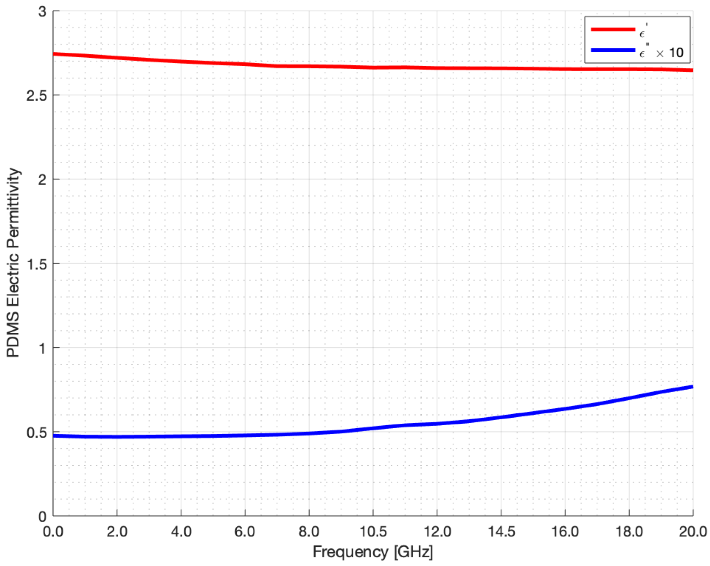
Figure 1. Relative dielectric permittivity and loss factor vs. frequency of PDMS sample.
Electronics 14 03766 g001
Figure 2. Geometry of the Fresnel lens. R1–R8 indicate the radii of the individual zones of the lens.
Electronics 14 03766 g002
Figure 3. CAD of the Fresnel lens antenna with the WR75 piramidal horn feeder.
Electronics 14 03766 g003
Figure 4. Electric field distribution at 15 GHz in yz plane.
Electronics 14 03766 g004
Figure 5. Antenna prototype, (a) PLA mold, and (b) PDMS lens.
Electronics 14 03766 g005
Figure 6. Variation of S 11 with frequency.
Electronics 14 03766 g006
Figure 7. Simulated vs. measured radiation pattern of WR75 Horn Antenna.
Electronics 14 03766 g007
Figure 8. Simulated vs. measured radiation pattern of PDMS lens Antenna.
Electronics 14 03766 g008
Table 1. Fresnel lens geometrical parameters.
ParametersValue [cm]
R 1 1.60
R 2 2.30
R 3 2.83
R 4 3.31
R 5 3.75
R 6 4.15
R 7 4.53
R 8 4.90
t 1 0.64
d0.82
Table 2. Fresnel lens fabrication methodologies performances comparison.
TechnolgiesMech. RobustnessCostTime for Fabrication
Additive Tech. (3D)LowHighHigh
CNC Miling. Mach.LowHighMedium
Company Custom MadeMediumVery HighVery High
Proposed Tech.Very HighLowMedium
Disclaimer/Publisher’s Note: The statements, opinions and data contained in all publications are solely those of the individual author(s) and contributor(s) and not of MDPI and/or the editor(s). MDPI and/or the editor(s) disclaim responsibility for any injury to people or property resulting from any ideas, methods, instructions or products referred to in the content.