Abstract
Iris recognition is currently considered the most promising biometric method and has been applied in many fields. Current commercial and research systems typically use software solutions running on a dedicated computer, whose power consumption, size and price are considerably high. This paper presents a hardware-based embedded solution for real-time iris segmentation. From an algorithmic point of view, the system consists of two steps. The first employs a YOLOX trained to detect two classes: eyes and iris/pupil. Both classes intersect in the last of the classes and this is used to emphasise the detection of the iris/pupil class. The second stage uses a lightweight U-Net network to segment the iris, which is applied only on the locations provided by the first stage. Designed to work in an Iris At A Distance (IAAD) scenario, the system includes quality parameters to discard low-contrast or low-sharpness detections. The whole system has been integrated on one MultiProcessor System-on-Chip (MPSoC) using AMD’s Deep learning Processing Unit (DPU). This approach is capable of processing the more than 45 frames per second provided by a 16 Mpx CMOS digital image sensor. Experiments to determine the accuracy of the proposed system in terms of iris segmentation are performed on several publicly available databases with satisfactory results.
1. Introduction
Briefly, biometric identification by iris recognition consists of using the unique pattern of the coloured and textured part of the eye (the iris) as each person’s characteristic “signature” and comparing it with those stored in a dataset to verify and authenticate the identity [1]. The uniqueness of the iris pattern makes this technique more robust and accurate for verification than other techniques based on different biometric characteristics. Apart from this, other relevant properties of the technique are its stability over time and its relatively easy accessibility. In addition, iris recognition techniques are also interesting in terms of cost. In iris recognition, there are no cards to replace periodically, and no RFID-blocking sleeves to prevent hacking. There is no contact with the camera, neither for registration nor for authentication, so there is no need to replace or clean them. All these features have made iris recognition technology attractive for a wide range of applications, ranging from access control to time management. The increasing adoption of multi-factor authentication services in defence, government organisations, and significantly, healthcare, is aiding the growth of the iris recognition market [2].
Many of these new applications would be more feasible if the system were able to work with the person in motion and at an increasing distance (more than 1 m) from them. The challenge is to design a system in which people do not have to collaborate to be identified. This is known as Iris At A Distance (IAAD) recognition [3]. By solving this problem, the two main limitations that restrict iris recognition performance (i.e., short acquisition distance and relatively high user cooperation) can be alleviated. On the other hand, a second relevant challenge is related to the ability of the system to be executed on a device with relatively low cost and consumption, ensuring that data processing will be brought closer to the source of data generation (edge computing). Most implementations in the edge-computing scenario are GPU-based, using devices that have a non-negligible cost and consumption. MultiProcessor System-on-Chips (MPSoCs)-based options can be an alternative with comparable quality and much lower power consumption [4].
In summary, this manuscript addresses the problem of embedding a real-time iris capture and segmentation system in a single MPSoC. The result is a system of relatively low power consumption (less than 6 W), size, and weight, with a reduced price compared to other solutions. The adopted solution is based on the design of a deep learning model, with two distinct stages. The first works as an attention mechanism, delineating the regions of interest in the image (the presence of the iris). The second stage analyses these regions to segment the iris patterns (if the image region actually includes the eye of the person). Specifically, the iris segmentation task determines which pixels in the images belong to the iris region. It is a fundamental step in successfully tackling iris recognition. Good segmentation allows the removal of artefacts, such as eyelashes and pupil, from the iris pattern. It also allows us to extract more discriminative features and thus obtain higher accuracy in the final recognition. Segmentation is conducted using an end-to-end trainable solution. This avoids intermediate processes (detection of radios, removal of artefacts) and enables the system to solve the problem in real time.
1.1. Contributions
The main contribution of this work is the design and development of a complete iris capture and segmentation system, embedded in a single MPSoC. The system employs a YOLOX to detect iris regions in the input images and a lightweight U-Net to segment the iris pattern of these regions, providing normalised iris patterns as output. Both solutions have been slightly modified to optimise resource use. To achieve this integration, two AMD/Xilinx Deep Processing Unit (DPU) cores have been deployed in the programmable logic part of the MPSoC. This approach forces the entire system to be optimised to reduce resource consumption in order to successfully utilise these cores. The result utilisation is close to the limit for some of the elements in the aforementioned programmable part of the MPSoC.
In addition, the system has been designed to solve the problem of remote iris recognition. The chosen parameters tuned the system to capture images without motion noise. The exposure time is very short, and the lighting is pulsed, with the shutter release time being slightly longer than the exposure time to obtain sharp shots. Moreover, since most of the captured images include out-of-focus eyes (due to the distance of the subject from the camera), the system filters out regions that have a low level of contrast or sharpness. The result is, therefore, a system capable of solving the problem of obtaining standardised iris patterns in an IAAD scenario. The speed of the entire system allows for the processing of more than 45 frames per second (fps) provided by a 16 Mpixel CMOS sensor. The quality of the segmentations has been validated using publicly available databases.
1.2. Organisation of the Paper
The rest of the paper is organised as follows: Section 2 briefly introduces the iris segmentation problem and some traditional and deep learning-based solutions. Section 3 provides an overview of the proposed methodology, detailing the acquisition setup and data collection. Section 4 elaborates on the embedding of the whole segmentation system in the MPSoC. Section 5 evaluates the accuracy of the proposed approach in terms of iris segmentation using publicly available databases. The resource utilisation and power consumption are also described in detail. Section 6 concludes the paper and describes future work.
2. Related Work
As in other fields of image processing, research on iris segmentation is divided into traditional methods—usually based, in this specific case, on the assumption that the internal and external contours that define the iris are circular—and approaches based on deep learning. The assumptions on which traditional methods are based require working with high-quality images [5]. They use differential operators [6] or the circular Hough transform [7] to detect contours that, as mentioned, are assumed to be circular and with a large difference in brightness on both sides of them. To improve both quality and speed, He et al. [8] proposed implementing iris detection using an Adaboost cascade and an elastic model, in which the centers and radii that define the iris contours are iteratively refined. Sutra et al. [9] proposed applying Viterbi’s algorithm on the image gradient processed by Anisotropic Smoothing. The process is applied at two scales. With the idea of increasing the quality of segmentation, Osorio-Roig et al. [10] propose an approach to the problem in which the classifier includes more classes apart from iris and non-iris (sclera, inner canthus, periocular region). These examples show that the most traditional approach involves high processing and a very manual solution that depends on the quality of the input image, which is difficult to generalise [5]. The generalisation problem is even more serious if we move to the framework of iris recognition at a distance and with people in motion. In this case, it is difficult to capture perfectly frontal or perfectly illuminated eyes. This affects the above-mentioned restrictions of circular contours and large differences in brightness on both sides of the contour. In addition, the system must cope with processing a large number of input images, many of which are out of focus, and should be efficiently discarded [11].
If we have a database of a certain size and the ground-truth of the images that make it up, Deep Learning techniques allow us to obtain good results even with poor-quality images [5]. Designed for a remote capture and people in motion framework, Liu et al. [12] propose the multi-scale fully convolutional network (MFCNs). It is an end-to-end method, with no pre- or post-processing steps. The UNet model [13] is a popular solution for image segmentation, which is able to perform well even when it is trained with a small amount of labelled data. Briefly, it includes a contracting path (the encoder part) and an expansive path (the decoder part). In the encoder part, increasingly abstract features are extracted by applying convolutions and downsampling. The spatial size decreases while the feature channels increases. On the other hand, the decoder recovers the original image size through upsampling. At each level of this part, skip connections are employed to combine decoder and encoder features. To preserve spatial information and eliminate the need for learning to upsample, the decoder part of the SegNet proposal [14] uses pooling indices computed in the max-pooling step of the corresponding encoder and performs a non-linear upsampling. The DeepLabV3++ [15] combines the pyramid pooling module and the encoder–decoder structure. The aim is to obtain rich semantic information from the encoder part while the decoder part recovers detailed object boundaries. The structure of the LinkNet [16] bypasses the spatial information directly from the encoder blocks to the corresponding decoder blocks. Instead of using skip connections, LinkNet employs cross-stage partial connections. UNet++ [17] aims to facilitate the integration of multi-scale features interconnecting the encoder and decoder parts of the UNet structure through dense skip connections. IrisDenseNet [18] is a densely connected convolutional network that, using better information gradient flow between the dense blocks, tries to solve the problem of segmenting the iris into low-quality images. The problem is, in many cases, the large number of parameters of the proposed solutions, which also implies a high processing time [19]. This is the case of the FD-UNet (Fully Dilated UNet architecture) [20] or the Dense UNet [21], both of which are based on the UNet architecture [13]. The PFSegIris approach [22] modifies the UNet structure to incorporate an efficient parallel attention mechanism between the encoder and the decoder. This mechanism enhances the discriminablity of iris region pixels. To achieve a more efficient UNet structure (with fewer parameters), Miron et al. [19] propose reducing the number of layers. Briefly, this architecture consists of 18 convolutional layers, nine 1 × 1 convolutional layers, three transpose convolutional layers, three max-pooling layers, and three concatenated layers. The number of parameters is finally equal to 148,017 (this value is reduced to 37,284 if the 18 convolution layers are replaced with separable convolutions). The ES-Net solution [23] is inspired by the UNet model. However, in order to gain efficiency, it uses spatial pyramid block for the encoder and decoder phases. To improve the accuracy of the model, an attention mechanism is utilised. Lei et al. [24] proposes an iris segmentation model that consist of two paths. The first one is a modified version of UNet, which employs in the encoder a depth-separable convolution instead of convolution and pooling layers. The second path consists of three layers of depth-separable convolutions. The outputs of these two paths are merged, with the segmented images finally being classified by a Sigmoid activation function.
3. Methodology
The aim of this research is to design and develop an efficient deep learning-based iris segmentation system on MPSoC. The deep learning model is designed to achieve high accuracy and minimal processing time for iris segmentation. It consists of two high-consuming stages, which are both integrated into an unique MPSoC. The resource utilisation and performance are, therefore, relevant topics. The former must be optimised to ensure that both stages have the best possible hardware options. The second involves balancing the complexity of the algorithms to achieve good results while keeping the response time as low as possible. The research implies designing the data acquisition setting, collecting a dataset, designing the proposed model, comparing it with recent approaches, deploying the model in the MPSoC, and finally evaluating the resource utilisation by the proposed approach and its performance in real-time implementation. The description of the data acquisition setup and the captured dataset are detailed below. Section 4 describes the proposed system, detailing the model employed to implement the iris detection and the iris segmentation stages.
3.1. Data Acquisition Setup
Despite the technical difficulties, several commercially available systems for IAAD exist. Among them, the Spanish SHS Consultores SL provides one solution. The AIRIM system (http://www.slideshare.net/SHSConsultores/datasheet-airim, accessed on 4 July 2025) can capture irises from a moving person situated at a distance from the camera. In AIRIM, the position of the sensor is fixed, and the people are required to walk through a ‘virtual’ corridor and look directly at the camera (see Figure 1). The system requires a moderate level of cooperation: looking forward, walking at a normal pace, and obviously not engaging in a behaviour intended to prevent the iris image capture. The recognition distance is 1.7 m and the system uses near infrared illuminators (NIR) at 940 nm, taking advantage of the sensibility of the deployed cameras.
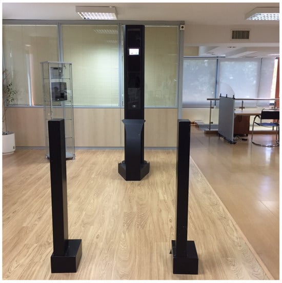
Figure 1.
The AIRIM system (SHS Consultores SL).
The proposed system for iris detection and segmentation makes use of the layout structure of the AIRIM system, whose electronic design has been completely modified. Briefly, it includes the iris image capture and processing units on a pole, facing the access point for monitoring. A Teledyne e2v EMERALD 16MP sensor (https://www.teledynevisionsolutions.com/company/news/e2v/teledyne-e2vs-emerald-12m-and-16m-image-sensors-enter-mass-production/, accessed on 17 September 2025) is employed. This sensor delivers 16 Mpixel images at a speed of 47 frames per second (fps). The optics is a LM100JC1MS from Kowa (https://www.kowa-lenses.com/LM100JC1MS-2-3-100mm-2MP-C-Mount-Lens/12040, accessed on 17 September 2025). Lighting is provided by a high-power LED device triggered by the capture module. The exposure time is 1 ms, allowing motion blur to be ruled out if the person walks at a normal speed (1–2 m per second). The major challenge for the system is that the depth of field is very small (approx. 15 cm). In any case, with the sensor working at its maximum speed (47 fps), 6–7 irises are captured for each passing sequence with sufficient quality to be recognised. The proposed capture and processing system provides the normalised iris patterns to an external computer, which is responsible for comparing this pattern with the database to close the identification. This last task is outside the scope of this manuscript.
The aim of the design is to make the captured image quickly accessible for further processing. The vision sensor delivers the image using 16 LVDS (low-voltage differential signaling) channels, with the frame grabber synthesised into the programmable logic (FPGA) of the MPSoC. This makes further image processing in the MPSoC highly efficient: no central processing unit or bus is required, and the processing can start immediately after reading the first pixel rows of the image. In a GPU-based solution, for instance, it is necessary to establish a communication channel with the frame grabber to minimise latency [25]. The device is built around a commercially available AMD/Xilinx Ultrascale+™ ZU4EV module, mounted on the TE0820-03-4DE21FA micromodule by Trenz (Hüllhorst, Germany) (https://shop.trenz-electronic.de/en/Products/Trenz-Electronic/TE08XX-Zynq-UltraScale/, accessed on 17 September 2025). Table 1 summarises the relevant features of this device.

Table 1.
Key features of the TE0820-03-4DE21FA module (https://docs.xilinx.com/v/u/en-US/ds891-zynq-ultrascale-plus-overview (accessed on 23 June 2025)).
Figure 2 shows a snapshot of the capture and processing unit. The image sensor is mounted on a Sensor board. This Sensor board and the Trenz micromodule are mounted on a Carrier board, which facilitates communication between sensor and Ultrascale+.
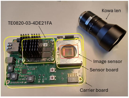
Figure 2.
The capture and processing unit. It includes the Kowa lens, the TE0820-03-4DE21FA, the image sensor, the sensor board and the carrier board (see text for details).
3.2. Datasets
As mentioned above, the system tries to solve two problems: (i) the detection of iris areas in the input images and (ii) the iris segmentation. Each problem is solved with a specific neural network, which requires a dataset for training. For the first problem, although there are databases with images of people at a distance from the camera, showing full faces with irises of sufficient quality (approximately 200 pixels/cm) (e.g., the CASIA-Iris Distance V4 dataset), we did not have a database with images of passing sequences, capturing images of people approaching the pole, with all the problems of motion, total or partial occlusions, reflections, etc. In order to train our model with data as close to the reality of the problem as possible, a dataset comprising 7071 images has been captured. Figure 3 shows some frames extracted from one of the sequences included on the dataset. Roboflow (https://roboflow.com/annotate (accessed on 15 September 2025)) was used to label images. Two classes have been labelled: eye and iris/pupil. Examples of labelling can be seen in the figure. In principle, only the iris/pupil class could have been labelled. However, having both classes allows for robust detection of the latter: an iris/pupil region will only be valid if it is within an eye region. This simple rule has allowed the system to discard false positives without missing any true positives. When you have labelled the eyes and irises/pupils present in the frames, it is important not to label those that are clearly out of focus. In our case, and contrary to what happens for example with the CASIA-Iris Distance V4 database, not all eyes in the image will be in focus. As long as the face of the person is located in the range of distances from the sensor that delimit the depth of field, the eyes are correctly in focus. Many of them will have the required quality to address iris recognition identification. When the face is outside this range, the eyes are out of focus and they should not be detected.
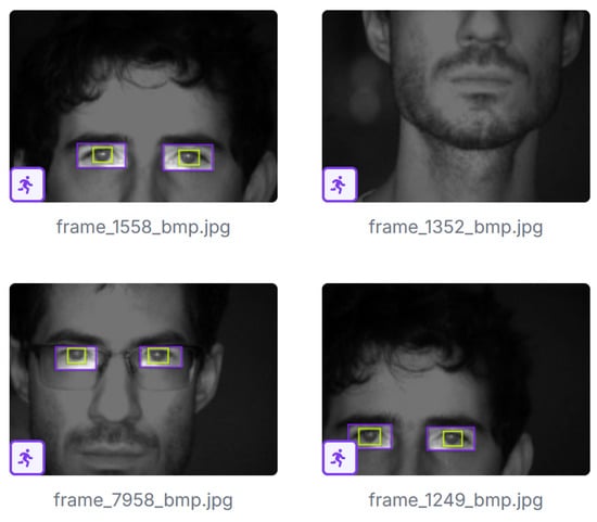
Figure 3.
Images used for training with eyes and iris/pupil annotations (purple and green boxes delineate eyes and irises/pupils, respectively).
On the other hand, a second dataset is needed to train the network used to segment the iris. In this case, the inputs can be focused eyes, and there are numerous publicly available databases. In particular, CASIA-Iris-V3-Interval (CASIA-IrisV3, http://www.cbsr.ia.ac.cn/IrisDatabase (accessed on 4 July 2025)) and IIT Delhi 1.0 [26] have been used. The ground truth for iris segmentation is available for both in the IRISSEG-CC (Halmstad University) and IRISSEG-EP (University of Salzburg) databases [27,28], respectively. To these datasets, we have added a set of 263 images captured by our system, whose ground truths have been manually generated. Among these, 79 images were acquired with contact lenses designed to conceal the iris, in order to ensure proper segmentation under this type of attack so that it can be effectively detected by the system in subsequent processing stages (see Figure 4 for representative examples of these images and their corresponding segmentations). After splitting, 1849 images from the CASIA dataset and 1568 images from the IITD dataset were used to train the segmenter. The aforementioned small set of 263 images captured with our system was also used for training. Validation employs 263 and 224 images from the CASIA and IITD datasets, respectively. The CASIA test set consists of 527 images while the IITD test set consists of 448 images.
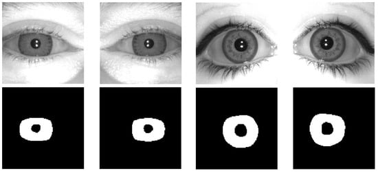
Figure 4.
Examples of iris images acquired with contact lenses designed to conceal the iris (top row) and their corresponding segmentations (bottom row).
4. Proposed Scheme for Iris Segmentation
4.1. The AMD Deep Processing Unit (DPU)
The heterogeneous architecture of the MPSoC, in which we have FPGA but also CPUs, allows us to balance flexibility and performance in the integration of the different layers that make up the CNN. As we describe in the next section, in our implementation, we have made use of the core deep learning processor Unit (DPU) from AMD/Xilinx. The DPU is a configurable design-time accelerator of the CNN for FPGAs. This core will be invoked from the MPSoC CPU to process the CNN layer by layer.
Briefly, the DPU consists internally of a computation engine, an instruction scheduler and an on-chip buffer controller (see Figure 5). After start-up, the DPU fetches instructions and decoders via the fetcher and decoder modules from external memory to control, via the Dispatcher, the operation of the computation engine. Vitis™ AI 3.5 provides a specialised instruction set for the DPU, allowing it to work efficiently with popular CNNs, such as YOLO or ResNet. The on-chip buffer controller manages on-chip memory to store data (buffered input triggers, intermediate feature maps and output metadata). The compute engine implements a deep pipeline design for convolution computation (the convolution engine), where a set of processing elements take full advantage of the fine-grained building blocks of the AMD/Xilinx device to build multipliers, adders, etc. As shown in Figure 5, the integration of the DPU with the processing system (PS) is performed via an AXI interconnect.
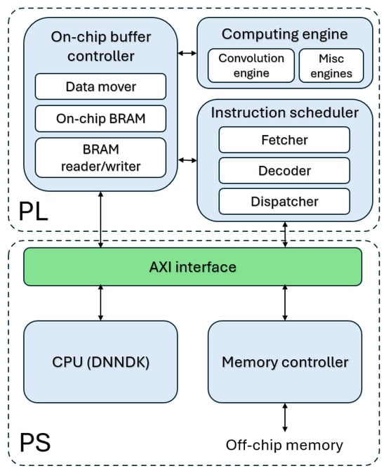
Figure 5.
Basic structure of AMD DPU and integration with the CPU.
In our case, the DPU reference design provided by Vitis AI 3.5 was implemented with AMD Vivado for the TE0820-03-4DE21FA board. After optimising the architecture, two B1024 DPUs have been successfully synthesised in the programmable part of the MPSoC. The B1024 configuration of the DPU (1024 operations/per clock) was synthesised with Low RAM Usage, Channel augmentation disabled, and Save argmax enabled. The chosen operating frequency of the DPU was 150 MHz. Petalinux 2023.2 was used to generate a Linux OS image for the TE0820-03-4DE21FA SoM.
4.2. Overview of the Proposed Architecture
Figure 6 illustrates the proposed architecture for deploying CNN-based eye detection and segmentation flow on an MPSoC-based platform. Each 4096 × 4096 pixel image provided by the EMERALD 16M sensor is stored, in its original size, in the DDR memory. Additionally, each image is resized to a size of 256 × 256 pixels. Eye detection is performed in this resized image. Previous work showed that this resolution is adequate for addressing this task [4,11]. This scaled image stream is made accessible to a first DPU, which is used to accelerate a YOLOX model. It is critical that this first CNN processes the 47 fps provided by the EMERALD sensor, as the number of focused eyes to be detected in each step sequence will be very small and we cannot miss a single frame of it. The output of this detection process is a stream of probable iris images. After discarding images that offer a low level of contrast or sharpness, this stream is made accessible to a second DPU, which allows us to accelerate a lightweight UNet model. The processing speed of this second CNN is not critical, but it should process the full set of iris images generated before the person leaves the access point. In our case the processing speed of the iris segmenter is 16 fps. In both CNN-based stages, the DPU is in charge of deep learning acceleration. The DPU cores require instructions to implement the network, which are prepared using the deep neural network compiler (DNNC) and deep neural network assembler (DNNAS) tools. Once an iris has been segmented, the subsequent steps of obtaining the normalised rectangular iris pattern and sending this pattern for final processing (recognition and/or anti-fraud detection) are carried out in the processing system (PS) of the MPSoC.
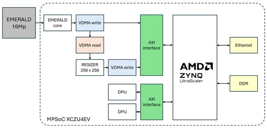
Figure 6.
Overview of the proposed architecture.
Next, we provide some details about the iris detection and segmentation stages.
4.3. Iris Detection
YOLOX (You Only Look Once X) [29] is an object detection framework that achieves superior speed and accuracy through a series of architectural and algorithmic improvements from older YOLO versions. It adopts an anchor-free detection approach, departing from traditional anchor-based methods. This eliminates the need to define and match multiple anchor boxes, simplifying the detection head and reducing computational overhead. As a result, the model achieves faster inference while maintaining high detection quality.
Unlike previous YOLO models that use a unified (coupled) head for both classification and localisation, YOLOX also introduces a decoupled head. This separates the branches responsible for object classification and bounding box regression. By isolating these tasks, YOLOX enables more efficient learning and faster convergence, contributing to improved inference performance.
To successfully deploy this network for eye detection, a modified version of the YOLOX nano was used. The input layer was reduced to accept images with 256 × 256 resolution to improve throughput and the activation function was modified from SiLU (Sigmoid Linear Unit) to the simpler ReLU (Rectified Linear Unit) to accommodate the available functions the hardware DPU core have. As aforementioned, two detection classes were configured: eyes and irises/pupils. Finally, using Vitis AI tools, the network was trained using QAT (Quantization-aware Training). QAT was performed using stochastic gradient descent (SGD) with a momentum of 0.9 and a weight decay of . A linear warm-up of five epochs from an initial learning rate of zero was applied, followed by a cosine decay schedule down to 5% of the initial learning rate (), over a total of 300 epochs. Quantization parameters were optimised using a learning rate ten times higher than that of the standard network weights. In this setup, the quantization parameters consist solely of the thresholds; learning the scale factor is unnecessary due to the use of power-of-two scaling, and zero-point optimisation is not required because symmetric quantization is employed.
As shown in Figure 7, the flow chart of the detection procedure includes a first preprocessing step, which is carried out by the resizer core on the FPGA that takes the 16MP from the Emerald sensor and transforms it to the required 256 × 256 image. As mentioned above, the YOLOX model detects both eyes and irises/pupils. To improve the rejection of false positives, a post-processing step is added to accept only detections of eyes that, within the bounding boxes, also have iris detection. Finally, although the database includes both in-focus and out-of-focus images and, by not labelling regions with clearly low contrast or sharpness as eyes or irises, YOLOX ensures to some extent that most of the detections are not of low quality, in the iris image stream, many samples may not meet the minimum quality requirements for contrast or sharpness. Taking into account the recommendations of ISO/IEC 29794-6:2015 [30] (https://www.iso.org/standard/54066.html (accessed on 17 September 2025)), two tests have been implemented to evaluate contrast and sharpness parameters in all iris images detected.
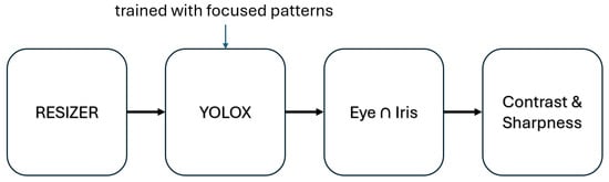
Figure 7.
Flow chart of the iris detection process.
Sharpness is evaluated using a 9 × 9 mask M, which is passed over the input image. This convolution generates an output , which is employed to obtain an initial power value ().
where is the size of the image.
To obtain a normalised score, the obtained spectral power is passed through a compressive non-linearity of the form
being c = 180,000 as defined in the ISO standard. This value is finally normalised to obtain a sharpness value s in the range [0, 1]
with and being two constant values, defined as 50.0 and 90.0, respectively.
With respect to the contrast parameter c, the value is computed using the following equation
I being the input image and its size, and the mean brightness value.
Only images that exceed a threshold of contrast and sharpness are provided to the iris segmenter. Table 2 summarises the results of applying these tests to different sets of images. In the CASIA and IITD databases, all images are in focus. However, the system rejects some of the images from the IITD. The last row of the table provides the results for a set of 433 images captured by our system. Focused images allow user identification, while unfocused images do not. The system has allowed 6 unfocused images out of 427 to pass, rejecting 1 valid image out of 46. For the sharpness filter, we used the parameters mentioned above. For the contrast filter, we heuristically set a threshold value of 1500.
Table 2.
Evaluation results of the proposed filter on different datasets.
4.4. Iris Segmentation
The network architecture for iris segmentation is a lightweight version of the U-Net CNN architecture [13]. Similar to other proposals [19,31], modifications aim to reduce inference time, number of parameters, and memory consumption. The proposed U-Net achieves a computational cost of 1.93 GFLOPs per forward pass, which highlights its efficiency compared to standard U-Net implementations. Table 3 presents a detailed description of the architecture.
Table 3.
Proposed U-Net architecture. The DoubleConv block consists of two consecutive convolutional layers, each followed by batch normalisation and a ReLU activation. Both convolutions use the same configuration.
The first preprocessing step consists of resizing the eye crop images from a spatial resolution of 256 × 256 pixels to 128 × 128 pixels. Subsequently, during each downsampling stage of the U-Net encoder, a Double Convolution block is applied, consisting of two consecutive convolutional layers with 3 × 3 kernels and padding of 1, each followed by batch normalisation and a ReLU activation. Each of these blocks is followed by a max pooling operation, which reduces the spatial dimensions by a factor of two. As a result, after each encoder stage, the output feature map has half the height and width of the previous stage and twice the depth. The initial Double Convolution block transforms the input image into a feature map of size 24 × 128 × 128. On the decoder side, each stage employs a 2D transposed convolution operator to upsample the spatial resolution by a factor of two while simultaneously halving the number of feature channels. The resulting upsampled output is concatenated with the feature map of matching spatial dimensions from the corresponding encoder stage via skip connections, and the combined tensor is processed through a Double Convolution block. In this way, the decoder progressively reconstructs the spatial structure of the input while refining high-level semantic information from the compressed feature representations. Figure 8 presents the architecture of the implemented U-Net used for iris segmentation. Finally, the raw segmentation output is post-processed by applying a sigmoid activation function to map the network’s output logits to a [0, 1] probability range. Subsequently, a fixed threshold is applied to obtain the final binary mask, isolating the iris region from non-iris areas within the input image.
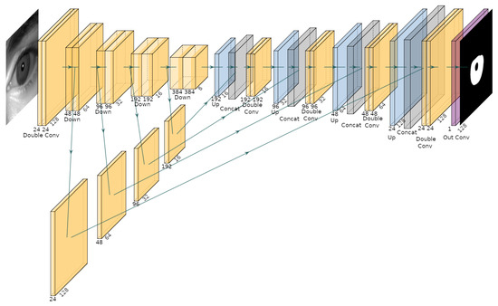
Figure 8.
Architecture of the implemented U-Net for iris segmentation.
Once the segmentation mask is obtained, one-dimensional histograms along the X and Y axes are computed to analyse the spatial distribution of the segmented iris region. By evaluating the slope of these histograms and applying empirically derived thresholds, the centre coordinates and radius of the iris are estimated. Subsequently, the centre and radius of the pupil are determined using the Hough Circle Transform, which is well-suited for detecting circular structures in binary images. Notably, the Hough Transform was not employed for iris localisation due to the significantly higher computational cost associated with processing a larger area. A diagram of the overall process and its corresponding results are presented in Figure 9.
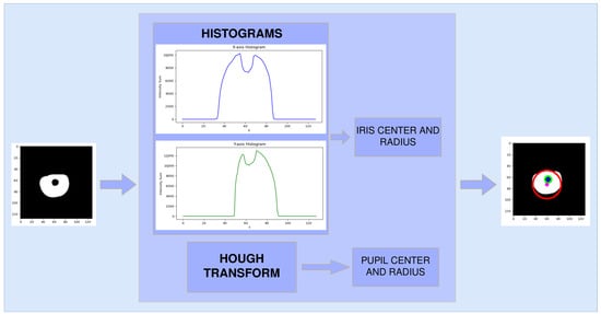
Figure 9.
Diagram illustrating the post-segmentation processing pipeline. The figure shows the extraction of X and Y histograms from the binary iris mask and the estimation of the iris and pupil centres and radii. The red and green circles delineates the iris and pupil regions, respectively.
During the segmentation stage, certain samples are discarded based on predefined anatomical constraints. A segmented eye is rejected if the iris radius is smaller than 16 or greater than 42 pixels, or if the pupil radius is smaller than 4 or greater than 14 pixels. Another rejection condition arises when the Euclidean distance between the estimated iris and pupil centers exceeds 70% of the iris radius. These constraints are imposed because violations may lead to a dysfunctional iris unwrapping process.
With regard to the process illustrated in Figure 9 for obtaining the centre of the iris, the initial boundary of the iris is established when the histogram slope is positive and its value exceeds 5000. Conversely, the final boundary of the iris is determined when the histogram slope becomes negative and its value falls below 5000. This procedure is applied independently to both the horizontal and vertical histograms, and the iris center is computed as the mean position of the detected boundaries.
The estimation of the iris radius and center using histogram analysis was introduced as a solution to reduce post-processing time within the recognition pipeline. Although visual inspection of the unrolled iris images suggested comparable accuracy with the Hough-based method, a small-scale evaluation was performed to quantify potential deviations. For this purpose, data from four different users were processed, yielding a total of 52 high-quality segmented iris samples (samples that successfully passed the initial filtering stage). The iris radius and center were calculated for each sample using both the histogram-based and the Hough-transform-based approaches. The comparative results are presented in Table 4. The experiment shows that while both methods provide similar average values, the Hough-based method exhibits a considerably higher variance in the estimation of the iris radius ( vs. ). This outcome highlights that the histogram-based approach is not only computationally more efficient but also more stable, thereby validating its integration in the proposed pipeline.
Table 4.
Comparison between histogram-based and Hough-transform-based estimation of iris radius and center (52 iris samples from 4 different users).
The next step in the processing pipeline involves resizing the binary segmentation mask from 128 × 128 to 256 × 256 pixels using nearest-neighbour interpolation, a method that preserves the discrete nature of the binary mask without introducing interpolation artifacts. Following this, the upsampled segmentation mask is applied to the original 256 × 256 input image via element-wise multiplication, effectively isolating the iris region from the rest of the image.
The previously estimated iris and pupil centres and radii, originally computed at 128 × 128 resolution, are then rescaled proportionally to match the new 256 × 256 resolution. This ensures spatial consistency in subsequent processing stages.
Finally, the segmented iris region undergoes Daugman’s rubber sheet normalisation [1]. This transformation remaps the iris region from Cartesian coordinates to the normalised polar representation, facilitating invariance to pupil dilation and iris size variation. This step is essential for enabling robust and consistent feature extraction across different subjects and imaging conditions. The complete process is shown in Figure 10. It is important to note that the final results of the algorithm depend not only on the segmentation but also on the correct location of the centres and the estimation of the radii. As can be seen in the image, the estimation could be improved. Algorithms such as the contour detection method [32], used by PFSegIris, could be used for this purpose. The problem is that, if they are synthesised in the PL of the MPSoC, these algorithms consume resources that are not available. If they are executed in the PS, the response time increases, making it impossible for the system to meet the requirements.
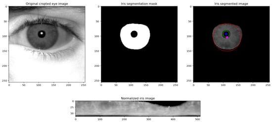
Figure 10.
Process for extracting the normalised iris (bottom row), starting from the captured eye image (leftmost image, top row), followed by the binary segmentation mask (second image, top row), and the segmented iris region (the red and green circles delineates the iris and pupil regions, respectively) (third image, top row).
5. Evaluation Results
5.1. Evaluation of the Detection Stage
The system has been intensively tested in a real environment, where natural lighting is not controlled and where people passing by the access point do not cooperate with the system. They are simply asked to walk past.
Addressing the detection problem first, Figure 11 shows how the system correctly detects irises in those images that show relatively high contrast and sharpness values. As mentioned above, this is critical, as capturing pass-by sequences of about three seconds, at 47 fps, the set of eye images can exceed 200–250. If all these eyes are passed to the segmentation stage we would need to process a very large number of images in order to discard them. Thanks to the contrast and sharpness tests, the number of images that are passed to the segmentation stage typically does not exceed 10–15 detections.
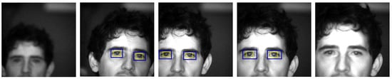
Figure 11.
Eye detection using the proposed approach (blue and yellow boxes delineate eyes and irises/pupils, respectively) (see text for details).
As for false positives, the simple rule applied to YOLOX predictions of only considering valid irises as those within an eye detection has allowed us to observe a qualitative improvement in detection performance. To qualitatively support this empirical hypothesis, we employed the Gradient-weighted Class Activation Mapping (Grad-CAM) technique [33,34]. Grad-CAM is a method designed to provide visual explanations for decisions made by a wide range of Convolutional Neural Network (CNN)-based models, thereby enhancing model interpretability and transparency. As illustrated in Figure 12, the first row shows the output from a YOLOX model trained exclusively with eye bounding boxes. In this case, the model incorrectly identifies the subject’s chin as an eye, a misclassification clearly highlighted by the corresponding Grad-CAM heatmap, which indicates attention in irrelevant facial regions. In contrast, the bottom row presents the output for the same input image using a YOLOX model trained with both eye and iris bounding boxes. This model correctly detects the eyes, and the Grad-CAM visualisation confirms that its attention is appropriately focused on the ocular region. Both models were evaluated using a confidence threshold of 0.6.
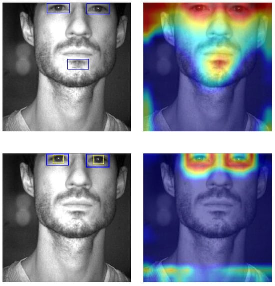
Figure 12.
Comparison of Grad-CAM visualisations and detection outputs between YOLOX models trained with different annotations. (Top row): model trained with eye-only bounding boxes (YOLOX prediction and Grad-CAM output). (Bottom row): model trained with eye and iris bounding boxes (YOLOX prediction and Grad-CAM output). Blue and yellow boxes delineate eyes and irises/pupils, respectively.
To quantitatively evaluate the improvement gained by using two classes instead of just one, we selected our own dataset of 3,653 images. All of them contain irises (usually two, but sometimes only one). Based on the data shown in Table 5, the ablation study has been performed and we can note that when the two-class solution is adopted, the false positive rate is smaller than when only single-class solutions are used. In any case, the false positive rate is very low and virtually all detections, in any of the three solutions, include the iris region.
Table 5.
Ablation study of the two-class and single-class solutions.
The detection system has been successfully evaluated with the CASIA v4 Distance database. The images in this dataset are frontal and of high quality, so the conditions are ideal to successfully solve the detection problem. As was the case in the study conducted by Ruiz-Beltran et al. [35], the ability of the method to work with different races and ages was evaluated using the Flickr database [36]. In the latter case, the detections are not valid for recognition, but if images of non-frontal faces or where hair partially covers the iris are discarded, the system works successfully.
5.2. Evaluation of the Segmentation Stage
The UNet model was quantized to 8-bit integers using symmetric power-of-two quantization. This scheme is particularly efficient for deployment on edge devices, as scaling by a power-of-two factor reduces to simple bit-shift operations. Although it is among the most fundamental quantization strategies, the experimental results demonstrate its effectiveness in practice. For the post-training quantization calibration, the CASIA test dataset was employed. Since label information is not required during this phase, only representative and diverse samples are necessary to capture the activation statistics.
The model implemented to segment the iris was initially evaluated on a computer with a graphics card, in a version implemented in floating-point precision (FP32). To synthesise it on the MPSoC, this precision had to be replaced by 8-bit integer precision (INT8). Table 6 shows the evaluation of these models on the two hardware platforms: NVIDIA RTX 3060 GPU and the XCZU4EV-1SFVC784I MPSoC platform with B1024 DPU architecture. The average DICE coefficient is employed to measure the similarity between the ground-truth masks and the obtained iris segmentations. Two datasets were used in this comparison. The CASIA-Iris-Interval is a subset of the CASIA v3.0 database, which contains 2655 iris images from 249 subjects. The image resolution is 320 × 280 pixels, and the images were acquired in an indoor scenario with a close-up infrared iris camera. The IIT Delhi Iris dataset contains 2240 images from 224 subjects. The image resolution is 320 × 240 pixels. Images were acquired using a JIRIS JPC1000 digital CMOS near-infrared camera in an indoor scenario. It can be seen that the average DICE values are almost the same on both platforms, with no significant performance degradation observed after quantization. This is essential, as our goal is to synthesise in the MPSoC a solution that offers the same quality as could be obtained using other hardware alternatives. On the other hand, there are relevant differences in inference times. Thus, the speed is reduced from almost 1000 fps in the GPU implementation to 40 fps in the MPSoC. It should be noted that the number of frames per second that can be processed will be further reduced by taking into account the other steps associated with iris segmentation. What is important is that this stage is able to process the image stream generated by the detection stage. Figure 13 illustrates the segmentation results obtained by our system on a representative set of iris images.
Table 6.
Comparison of average DICE coefficients and inference times for each hardware platform and dataset (see text).
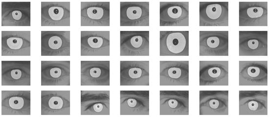
Figure 13.
Iris segmentation results using the proposed approach.
Table 7 shows the results obtained via different approaches using the IITD dataset. The proposed method provides an average DICE coefficient that is higher than that of other, more complex approaches, with a number of parameters that is also lower than that required by other methods. We have tried to synthesise other options, such as ES-Net, in the MPSoC, but the resource consumption and inference time did not meet the requirements of our system. As Miron et al. [19] pointed out, the main problem of the proposed task-specialised UNet solution is that there is no guarantee that it can be used in other applications. In our case, the problem is even greater, as the design has been optimised to run on the B1024 DPU processing a maximum number of frames per second (16 fps) that has never been exceeded in our scenario.
Table 7.
Comparison of the proposed solution with similar approaches using the IITD dataset.
5.3. Other Relevant Key Performance Indicators
One of the critical aspects of this proposal is the optimisation of resource consumption. As a first reference, the third column of Table 8 shows the resource utilisation for a design that integrates only eye detection (one B1600 DPU) and a module that uses HDMI to display results [35]. It can be seen how some of the resources are used in a high percentage (mainly LUT and URAM). The fourth column of Table 8 shows the resource utilisation for the design described in this work. All resources in the DPUs operate at 150 MHz except for the DSPs, which run at 2 × 150 MHz (300 MHz). This operating frequency value could have been increased, thus achieving a higher process speed. However, this strategy was not chosen in order to avoid excessive heating of a device that has to work uninterruptedly for long periods of time. The power consumption of the proposed scheme is 5.315 W.
Table 8.
Resource utilisation for the design described in [35] and the proposed design (both synthesized in the XCZU4EV-1SFVC784I).
In order to evaluate the robustness of the system under high-workload conditions, we conducted a stress test in parallel with the complete processing pipeline, executing multiple runs and recording the processing time of each stage. For the Filter and Pupil/Iris radius and center estimation stages, the rejection rate was also measured.
To ensure that real-time constraints are satisfied, the Detection + Filter process runs concurrently with the Preprocessing + Segmentation + Radius/Center estimation + Unroll Iris process, and both communicate via sockets. In the second process, a circular buffer with a capacity of 2000 samples was implemented, allowing the system to continue operating seamlessly in the event of overload; only the oldest samples would be discarded. Importantly, during our experiments, the buffer was never observed to reach its maximum capacity.
In each execution, a sequence of 100–150 images was acquired; however, only 5–10 typically met the quality criteria and successfully passed the filtering stage. A small proportion of false positives may also have passed the filter, as reported in Table 2. Once the subject exited the depth of field, the system had approximately one second to process all valid eye detections before the individual left the corridor. The processing times and rejection rates of each stage reported in Table 9 demonstrate that, even under high-load conditions, the second process consistently met the soft real-time deadline.
Table 9.
Performance summary for different processing stages.
6. Conclusions and Future Work
This paper shows the implementation of a complete iris capture, detection, and segmentation system in a single MPSoC. Two CNNs based on deep learning are designed: YOLOX for iris detection and a lightweight UNet for iris segmentation. The system works successfully in an IAAD environment, where normalised iris patterns are extracted from moving people passing through an access point without cooperating with the system. The patterns obtained have been shown to be valid for both recognition and identification of textured contact lens fraud.
Although the proposed approach works correctly, the employed dataset is not large enough for sufficient generalisation. The current dataset for iris detection only includes images of Caucasian people (specifically Hispanic people) and in a very specific age range (around 20–35 years of age). It should be increased to consider all ethnicities and the full age range, ensuring that the system works correctly in all cases. In the case of segmentation, having used external databases, there is greater diversity. But in any case, the size and diversity of the dataset should also be increased. Thus, the robustness of the proposal will be improved. Further extension of this work should consider including the iris recognition task within the MPSoC. One option is to consider a solution that integrates iris segmentation, feature extraction, and matching into a unified model [39]. The problem with these solutions is that they are more difficult to debug, as many tasks are mixed in a single network. Therefore, we are studying the option of moving the design to a platform with more resources in the PL, and including recognition as a third inference model (accelerated using a third DPU).
Author Contributions
Conceptualization, C.R.-B., M.G.-G. and A.B.; methodology, C.R.-B. and A.B.; software, Ó.P. and C.R.-B.; validation, Ó.P., C.R.-B. and A.B.; formal analysis, Ó.P., C.R.-B. and A.B.; investigation, Ó.P. and C.R.-B.; resources, Ó.P. and C.R.-B.; data curation, Ó.P. and C.R.-B.; writing—original draft preparation, Ó.P., C.R.-B. and A.B.; writing—review and editing, Ó.P., C.R.-B. and A.B.; visualization, Ó.P., C.R.-B. and A.B.; supervision, M.G.-G. and A.B.; project administration, M.G.-G. and A.B.; funding acquisition, M.G.-G. and A.B. All authors have read and agreed to the published version of the manuscript.
Funding
This work has been supported by grants CPP2021-008931 and PID2022-137344OB-C32, funded by MCIN/AEI/10.13039/501100011033 and by the European Union NextGenerationEU/PRTR (for the first one), and “ERDF A way of making Europe” (for the second one).
Data Availability Statement
The data presented in this study are openly available in https://universe.roboflow.com/practicasana/eye-iris-dataset-dndqh/dataset/1 (accessed on 17 September 2025).
Acknowledgments
Portions of the research in this paper use the CASIA-IrisV3 and CASIA-IrisV4 collected by the Chinese Academy of Sciences—Institute of Automation (CASIA). A dataset was also captured with the proposed system in a real scenario. We thank Yael Casquet, Ana Barrio, and Paula M. Lozano, for their work annotating the captured sequences.
Conflicts of Interest
The authors declare no conflicts of interest.
References
- Daugman, J. How iris recognition works. IEEE Trans. Circuits Syst. Video Technol. 2004, 14, 21–30. [Google Scholar] [CrossRef]
- Mohammed, R.; Ali Ahmed, A. Iris Recognition Technology: Principles, Mechanism, and Market Forecasting (2022–2030). In Proceedings of the 5th International African Conference on Current Studies, Cairo, Egypt, 2–5 February 2022. [Google Scholar]
- Nguyen, K.; Fookes, C.; Jillela, R.; Sridharan, S.; Ross, A. Long range iris recognition: A survey. Pattern Recognit. 2017, 72, 123–143. [Google Scholar] [CrossRef]
- Ruiz-Beltrán, C.A.; Romero-Garcés, A.; González, M.; Pedraza, A.S.; Rodríguez-Fernández, J.A.; Bandera, A. Real-time embedded eye detection system. Expert Syst. Appl. 2022, 194, 116505. [Google Scholar] [CrossRef]
- Chen, Y.; Gan, H.; Chen, H.; Zeng, Y.; Xu, L.; Heidari, A.A.; Zhu, X.; Liu, Y. Accurate iris segmentation and recognition using an end-to-end unified framework based on MADNet and DSANet. Neurocomputing 2023, 517, 264–278. [Google Scholar] [CrossRef]
- Daugman, J. High confidence visual recognition of persons by a test of statistical independence. IEEE Trans. Pattern Anal. Mach. Intell. 1993, 15, 1148–1161. [Google Scholar] [CrossRef]
- Masek, L. Recognition of Human Iris Patterns for Biometric Identification. Ph.D. Thesis, University of Western Australia, Crawley, Australia, 2003. [Google Scholar]
- He, Z.; Tan, T.; Sun, Z.; Qiu, X. Toward Accurate and Fast Iris Segmentation for Iris Biometrics. IEEE Trans. Pattern Anal. Mach. Intell. 2009, 31, 1670–1684. [Google Scholar] [CrossRef] [PubMed]
- Sutra, G.; Garcia-Salicetti, S.; Dorizzi, B. The Viterbi algorithm at different resolutions for enhanced iris segmentation. In Proceedings of the 2012 5th IAPR International Conference on Biometrics (ICB), New Delhi, India, 29 March–1 April 2012; pp. 310–316. [Google Scholar] [CrossRef]
- Osorio-Roig, D.; Morales-González, A.; Garea-Llano, E. Semantic Segmentation of Color Eye Images for Improving Iris Segmentation. In Progress in Pattern Recognition, Image Analysis, Computer Vision, and Applications; Mendoza, M., Velastín, S., Eds.; Springer: Cham, Switzerland, 2018; pp. 466–474. [Google Scholar]
- Ruiz-Beltrán, C.A.; Romero-Garcés, A.; González-García, M.; Marfil, R.; Bandera, A. Real-Time Embedded Eye Image Defocus Estimation for Iris Biometrics. Sensors 2023, 23, 7491. [Google Scholar] [CrossRef] [PubMed]
- Liu, N.; Li, H.; Zhang, M.; Liu, J.; Sun, Z.; Tan, T. Accurate iris segmentation in non-cooperative environments using fully convolutional networks. In Proceedings of the 2016 International Conference on Biometrics (ICB), Halmstad, Sweden, 13–16 June 2016; pp. 1–8. [Google Scholar] [CrossRef]
- Ronneberger, O.; Fischer, P.; Brox, T. U-Net: Convolutional Networks for Biomedical Image Segmentation. In Medical Image Computing and Computer-Assisted Intervention—MICCAI 2015; Navab, N., Hornegger, J., Wells, W.M., Frangi, A.F., Eds.; Springer: Cham, Switzerland, 2015; pp. 234–241. [Google Scholar]
- Badrinarayanan, V.; Kendall, A.; Cipolla, R. SegNet: A Deep Convolutional Encoder-Decoder Architecture for Image Segmentation. IEEE Trans. Pattern Anal. Mach. Intell. 2017, 39, 2481–2495. [Google Scholar] [CrossRef]
- Chen, L.C.; Zhu, Y.; Papandreou, G.; Schroff, F.; Adam, H. Encoder-Decoder with Atrous Separable Convolution for Semantic Image Segmentation. In Computer Vision—ECCV 2018; Ferrari, V., Hebert, M., Sminchisescu, C., Weiss, Y., Eds.; Springer: Cham, Switzerland, 2018; pp. 833–851. [Google Scholar]
- Chaurasia, A.; Culurciello, E. LinkNet: Exploiting encoder representations for efficient semantic segmentation. In Proceedings of the 2017 IEEE Visual Communications and Image Processing (VCIP), St. Petersburg, FL, USA, 10–13 December 2017; pp. 1–4. [Google Scholar] [CrossRef]
- Zhou, Z.; Rahman Siddiquee, M.M.; Tajbakhsh, N.; Liang, J. UNet++: A Nested U-Net Architecture for Medical Image Segmentation. In Deep Learning in Medical Image Analysis and Multimodal Learning for Clinical Decision Support; Stoyanov, D., Taylor, Z., Carneiro, G., Syeda-Mahmood, T., Martel, A., Maier-Hein, L., Tavares, J.M.R., Bradley, A., Papa, J.P., Belagiannis, V., et al., Eds.; Springer: Cham, Switzerland, 2018; pp. 3–11. [Google Scholar]
- Arsalan, M.; Naqvi, R.A.; Kim, D.S.; Nguyen, P.H.; Owais, M.; Park, K.R. IrisDenseNet: Robust Iris Segmentation Using Densely Connected Fully Convolutional Networks in the Images by Visible Light and Near-Infrared Light Camera Sensors. Sensors 2018, 18, 1501. [Google Scholar] [CrossRef]
- Miron, C.; Pasarica, A.; Manta, V.; Timofte, R. Efficient and robust eye images iris segmentation using a lightweight U-net convolutional network. Multimed. Tools Appl. 2022, 81, 14961–14977. [Google Scholar] [CrossRef]
- Zhang, W.; Lu, X.; Gu, Y.; Liu, Y.; Meng, X.; Li, J. A Robust Iris Segmentation Scheme Based on Improved U-Net. IEEE Access 2019, 7, 85082–85089. [Google Scholar] [CrossRef]
- Wu, X.; Zhao, L. Study on Iris Segmentation Algorithm Based on Dense U-Net. IEEE Access 2019, 7, 123959–123968. [Google Scholar] [CrossRef]
- Dong, L.; Liu, Y.; Zhu, X. PFSegIris: Precise and Fast Segmentation Algorithm for Multi-Source Heterogeneous Iris. Algorithms 2021, 14, 261. [Google Scholar] [CrossRef]
- Pourafkham, B.; Khotanlou, H. ES-Net: Unet-based model for the semantic segmentation of Iris. Multimed. Tools Appl. 2025, 84, 12395–12416. [Google Scholar] [CrossRef]
- Lei, S.; Shan, A.; Liu, B.; Zhao, Y.; Xiang, W. Lightweight and efficient dual-path fusion network for iris segmentation. Sci. Rep. 2023, 13, 14034. [Google Scholar] [CrossRef]
- Benke, I.; Marković, B.E.; Pavlović, I.; Milošević, M.; Grbić, R. Software solution stack for data transfer on a frame grabber platform. In Proceedings of the 2019 Zooming Innovation in Consumer Technologies Conference (ZINC), Novi Sad, Serbia, 29–30 May 2019; pp. 39–43. [Google Scholar] [CrossRef]
- Kumar, A.; Passi, A. Comparison and combination of iris matchers for reliable personal authentication. Pattern Recognit. 2010, 43, 1016–1026. [Google Scholar] [CrossRef]
- Alonso-Fernandez, F.; Bigun, J. Near-infrared and visible-light periocular recognition with Gabor features using frequency-adaptive automatic eye detection. IET Biom. 2015, 4, 74–89. [Google Scholar] [CrossRef]
- Hofbauer, H.; Alonso-Fernandez, F.; Wild, P.; Bigun, J.; Uhl, A. A Ground Truth for Iris Segmentation. In Proceedings of the 2014 22nd International Conference on Pattern Recognition, Stockholm, Sweden, 24–28 August 2014; pp. 527–532. [Google Scholar] [CrossRef]
- Ge, Z.; Liu, S.; Wang, F.; Li, Z.; Sun, J. YOLOX: Exceeding YOLO Series in 2021. arXiv 2021, arXiv:2107.08430. [Google Scholar] [CrossRef]
- ISO/IEC 29794-6:2015; Information Technology—Biometric Sample Quality—Part 6: Iris Image Data. ISO: Geneva, Switzerland, 2015.
- Safarov, F.; Khojamuratova, U.; Komoliddin, M.; Kurbanov, Z.; Tamara, A.; Nizamjon, I.; Muksimova, S.; Cho, Y.I. Lightweight Evolving U-Net for Next-Generation Biomedical Imaging. Diagnostics 2025, 15, 1120. [Google Scholar] [CrossRef]
- Suzuki, S.; be, K. Topological structural analysis of digitized binary images by border following. Comput. Vision Graph. Image Process. 1985, 30, 32–46. [Google Scholar] [CrossRef]
- Selvaraju, R.R.; Cogswell, M.; Das, A.; Vedantam, R.; Parikh, D.; Batra, D. Grad-CAM: Visual Explanations from Deep Networks via Gradient-Based Localization. Int. J. Comput. Vis. 2019, 128, 336–359. [Google Scholar] [CrossRef]
- Fernandez, F.G. TorchCAM: Class Activation Explorer. 2020. Available online: https://github.com/frgfm/torch-cam (accessed on 15 September 2025).
- Ruiz-Beltrán, C.A.; Romero-Garcés, A.; González-García, M.; Marfil, R.; Bandera, A. FPGA-Based CNN for Eye Detection in an Iris Recognition at a Distance System. Electronics 2023, 12, 4713. [Google Scholar] [CrossRef]
- Karras, T.; Laine, S.; Aila, T. A Style-Based Generator Architecture for Generative Adversarial Networks. arXiv 2018, arXiv:1812.04948. [Google Scholar]
- Guan, S.; Khan, A.A.; Sikdar, S.; Chitnis, P.V. Fully Dense UNet for 2-D Sparse Photoacoustic Tomography Artifact Removal. IEEE J. Biomed. Health Inform. 2020, 24, 568–576. [Google Scholar] [CrossRef] [PubMed]
- Zhao, H.; Shi, J.; Qi, X.; Wang, X.; Jia, J. Pyramid Scene Parsing Network. In Proceedings of the 2017 IEEE Conference on Computer Vision and Pattern Recognition (CVPR), Honolulu, HI, USA, 21–26 July 2017; pp. 6230–6239. [Google Scholar] [CrossRef]
- Hu, Q.; Yin, S.; Ni, H.; Huang, Y. An End to End Deep Neural Network for Iris Recognition. Procedia Comput. Sci. 2020, 174, 505–517. [Google Scholar] [CrossRef]
Disclaimer/Publisher’s Note: The statements, opinions and data contained in all publications are solely those of the individual author(s) and contributor(s) and not of MDPI and/or the editor(s). MDPI and/or the editor(s) disclaim responsibility for any injury to people or property resulting from any ideas, methods, instructions or products referred to in the content. |
© 2025 by the authors. Licensee MDPI, Basel, Switzerland. This article is an open access article distributed under the terms and conditions of the Creative Commons Attribution (CC BY) license (https://creativecommons.org/licenses/by/4.0/).