Harmonic Analysis and Elimination of Transmission Scheme Based on DRU for Medium-Frequency Offshore Wind Farms
Abstract
1. Introduction
- 1.
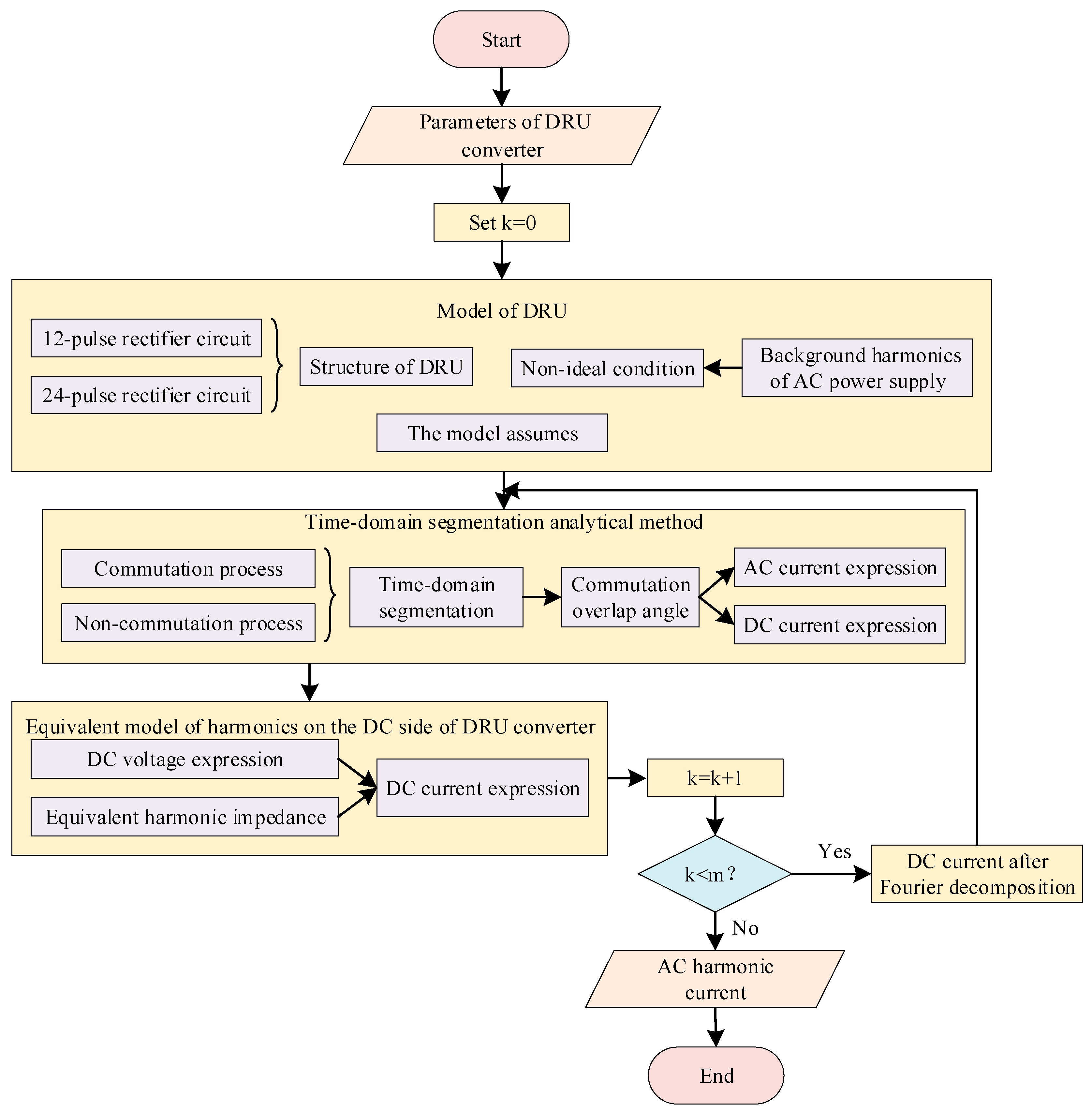
- A time-domain segmentation analytical method is proposed for accurate calculation of harmonic currents on the AC side in DRU;
- 2.
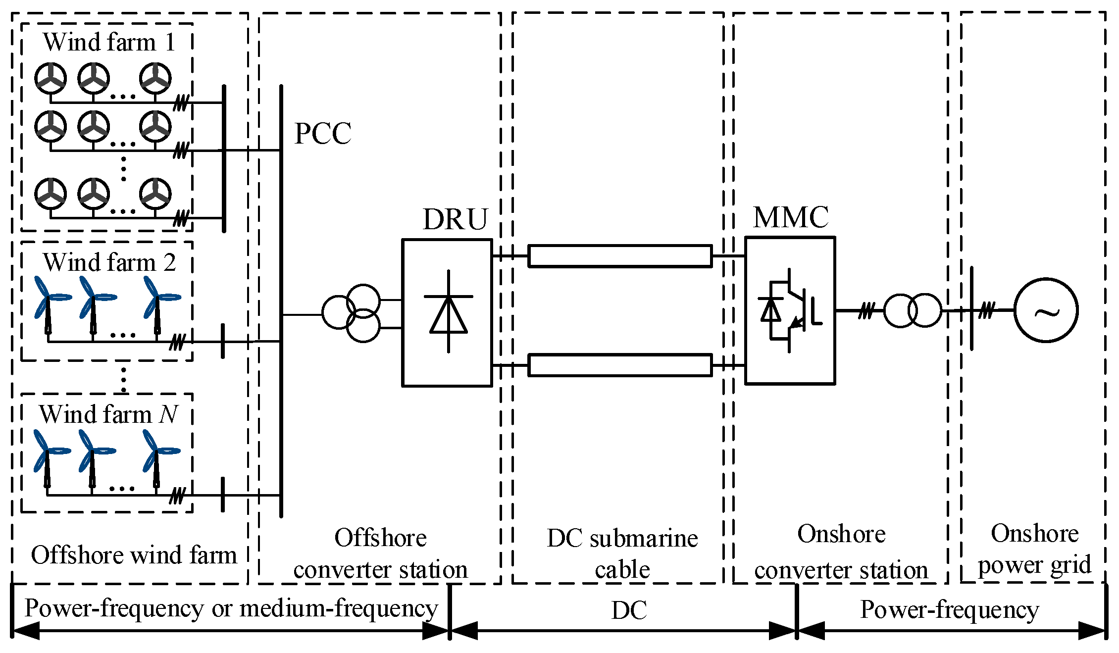
- An equivalent modeling approach is developed for the offshore AC network within offshore wind farm integration systems to facilitate harmonic analysis at node PCC;
- 3.
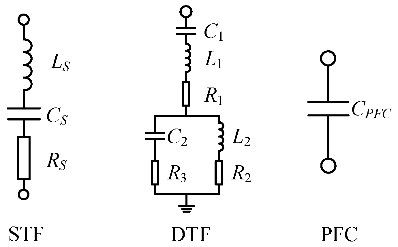
- A coordinated design methodology for AC filtering and reactive power compensation is introduced, tailored to different fundamental frequencies and DRU configurations.
2. Harmonic Analysis of DRU
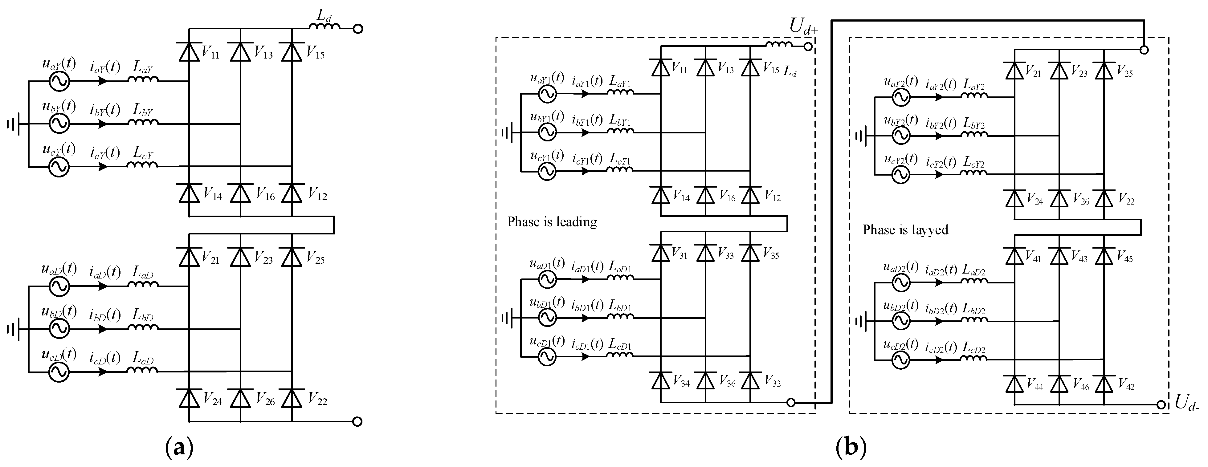
2.1. Topological Structure of DRU Converter
- The DC current is treated as a constant when calculating the commutation overlap angle;
- Due to the decoupling effect of the DC system on AC interactions, the electrical quantities on the rectifier side and inverter side are mutually decoupled;
- The reactance in the system is significantly larger than the resistance, allowing the system resistance to be neglected;
- The winding configuration of the converter transformer prevents the zero-sequence current component from being transmitted to the valve side of the converter transformer. Therefore, the AC voltage considers only the positive-sequence and negative-sequence components, with no zero-sequence component.
2.2. Calculation Method of Harmonic Current of DRU Based on 12-Pulse Rectifier Circuit
2.2.1. Calculation of Harmonic Current on the AC Side
2.2.2. Calculation of Harmonic Current on the DC Side
2.2.3. Iterative Calculation of Harmonic Current on the AC Side
2.3. Calculation of DRU Harmonic Current Based on 24-Pulse Rectifier Circuit
2.4. Analysis of Examples
3. Calculation and Elimination of Harmonic of Offshore Wind Farm Integration Schemes
3.1. An Equivalent Model of Offshore Wind Farms for Harmonic Analysis
3.2. Claculation of Harmonics
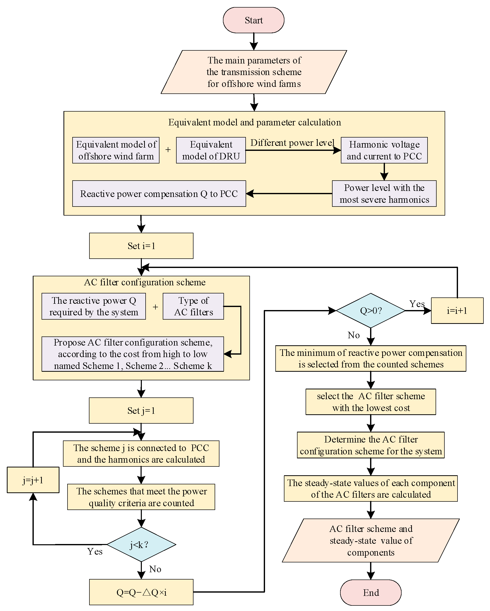
3.3. Design Methodology for AC Filtering and Reactive Power Compensation
- 1.
- Calculate the harmonic voltage without AC filters;
- 2.
- Determine the most severe harmonic scenario for a given frequency and DRU configuration;
- 3.
- Calculate the required reactive power compensation;
- 4.
- Design the configurations of AC filters;
- 5.
- Calculate the harmonic voltage with AC filters;
- 6.
- Determine the optimal filter design by minimizing reactive power compensation requirements and selecting the most cost-effective AC filter arrangement.
4. Analysis of Examples
- DRU power level: evaluated from 10% to 100% of rated power with 10% increments;
- Fundamental frequency: 50 Hz, 100 Hz, and 150 Hz;
- DRU topology: 12-pulse and 24-pulse rectifier circuit.
4.1. Key Parameters of the Offshore Wind Power Transmission System
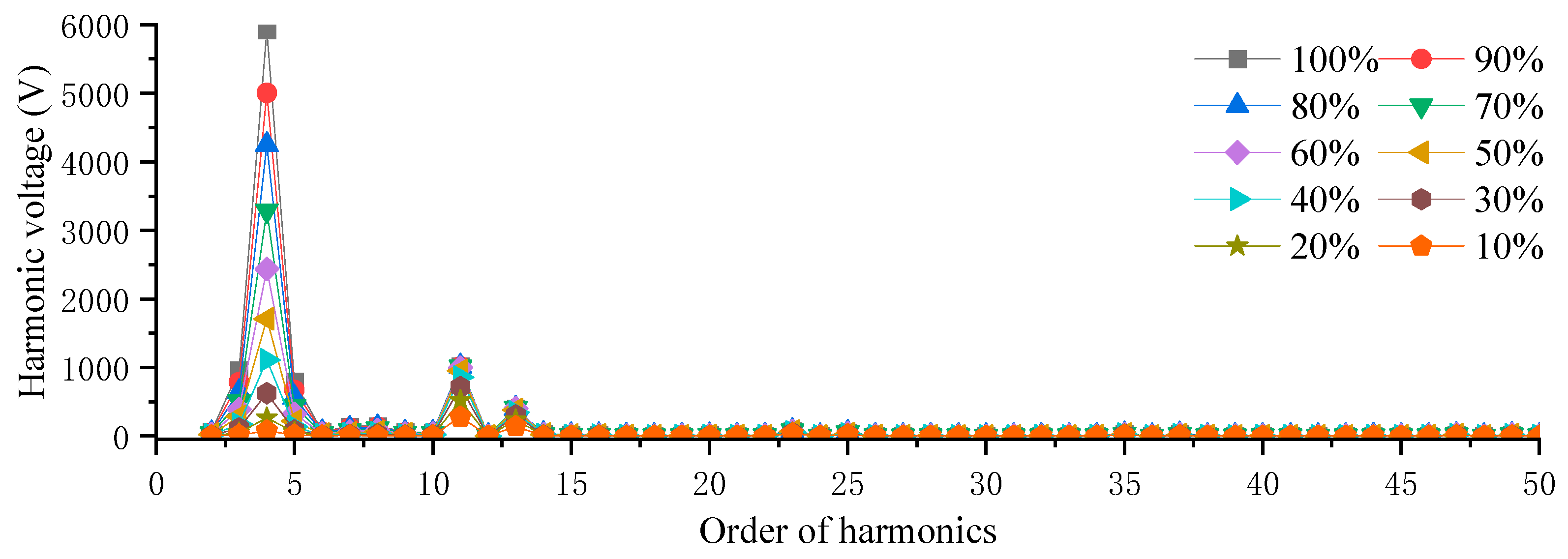
4.2. Harmonic Calculation and Analysis
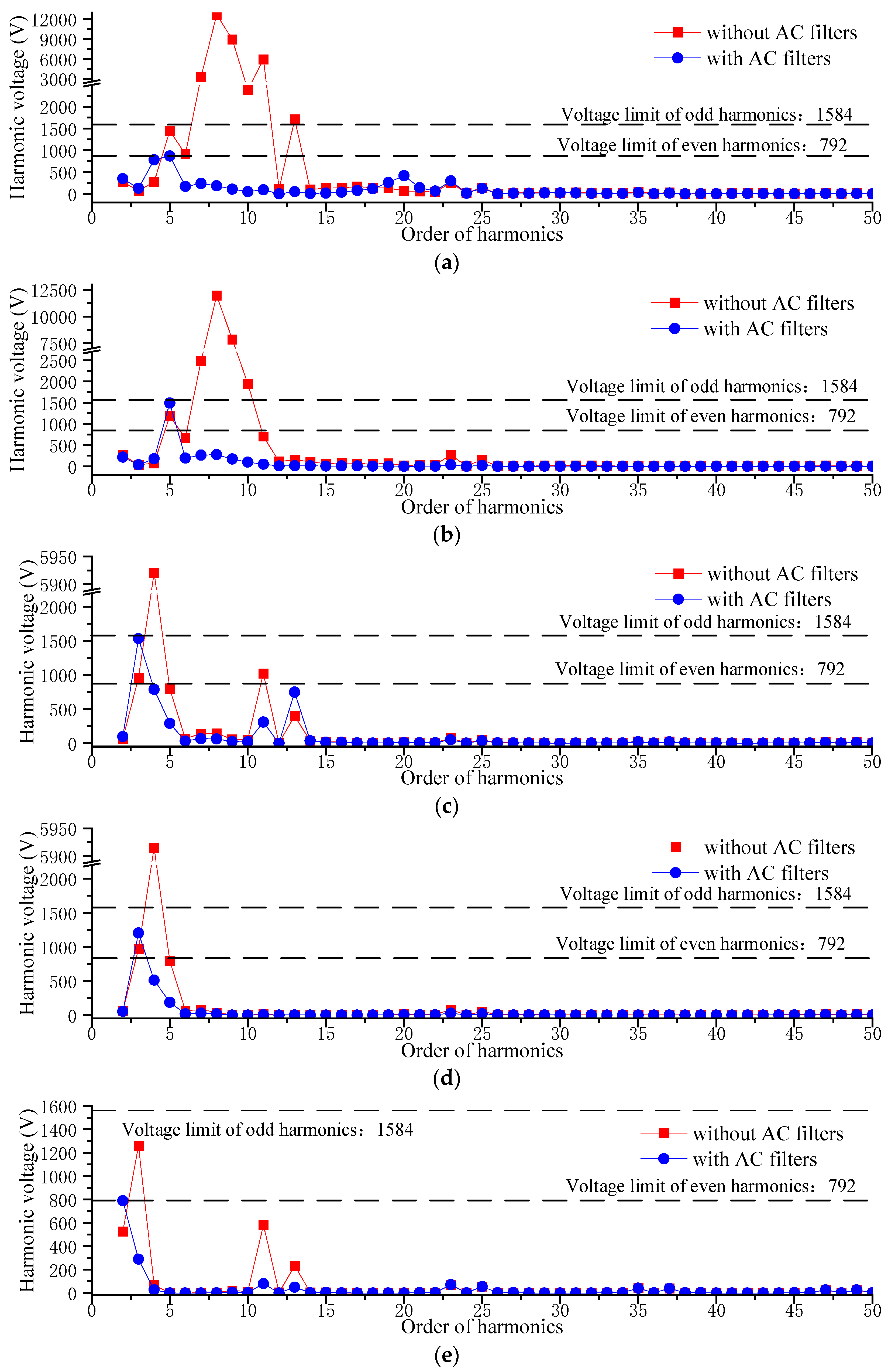
4.3. Design Methodology for AC Filtering and Reactive Power Compensation
5. Conclusions
- This paper proposes a time-domain segmentation analytical calculation method applicable to the AC side harmonic current of DRU. The AC side harmonic current and the commutation overlap angle are derived by mathematical methods. The DC current decomposed by Fourier is substituted into the time-domain piecewise analytical method for iterative solution, thereby obtaining a more accurate equivalent model of DRU. It is compared with the time-domain simulation method to verify its correctness.
- This paper proposes a modeling method for the equivalent model of the offshore AC part of the offshore wind farm integration schemes and presents a harmonic calculation and analysis method for the harmonic analysis problem of node PCC under the dual influence of offshore wind farms and DRU. It proves that the increase of fundamental frequency and DRU pulse number has a suppression effect on harmonics.
- Aiming at the harmonic control problem of offshore wind farm integration schemes with different fundamental frequencies and different DRU structures, this paper proposes an AC filtering and reactive power compensation design scheme. Firstly, this paper constructs a collaborative design framework for AC filtering and reactive power compensation of the offshore wind power transmission system, including six key links. By comparing and analyzing the combinations of six different fundamental frequencies and DRU structures, the optimal AC filter configuration scheme is obtained, providing reference for the actual offshore wind power project.
Author Contributions
Funding
Data Availability Statement
Conflicts of Interest
References
- Yang, B.; Liu, B.; Zhou, H.; Wang, J.; Yao, W.; Wu, S.; Shu, H.; Ren, Y. A critical survey of technologies of large offshore wind farm integration: Summary, advances, and perspectives. Prot. Control Mod. Power Syst. 2022, 7, 233–264. [Google Scholar] [CrossRef]
- Wang, X.; Zhao, B.; Huang, M.; Ye, R. Research of Integration Methods Comparison and Key Design Technologies for Large Scale Long Distance Offshore Wind Power. J. Glob. Energy Interconnect. 2019, 2, 138–145. [Google Scholar]
- Gao, Y.; Tahir, M.; Siano, P.; Bi, Y.; Hu, S.; Yang, J. Optimization of renewable energy-based integrated energy systems: A three-stage stochastic robust model. Appl. Energy 2025, 377, 124635. [Google Scholar] [CrossRef]
- Xu, Z. Main Schemes and Key Technical Problems for Grid Integration of Offshore Wind Farm. Autom. Electr. Power Syst. 2022, 46, 1–10. [Google Scholar]
- Singh, B.; Singh, B.N.; Chandra, A.; Al-Haddad, K.; Pandey, A.; Kothari, D.P. A review of three phase improved power quality AC-DC converters. IEEE Trans. Ind. Electron. 2004, 51, 641–660. [Google Scholar] [CrossRef]
- Wang, Z.; Liu, J. Power Electronics, 5th ed.; China Machine Press: Beijing, China, 2009. [Google Scholar]
- Tang, Y.; Zhang, Z.; Xu, Z. Diode Rectifier Unit Based LFAC Transmission for Offshore Wind Farm Integration. Electr. Power 2020, 53, 44. [Google Scholar]
- Meng, F.; Yang, S.; Yang, W. Overview of multi-pulse rectifier technique. Electr. Power Autom. Equip. 2012, 32, 9–22. [Google Scholar]
- Fathollahi, A.; Andresen, B. Power Quality Analysis and Improvement of Power-to-X Plants Using Digital Twins: A Practical Application in Denmark. IEEE Trans. Energy Convers. 2025, 40, 1909–1921. [Google Scholar] [CrossRef]
- Ma, H.; Zhang, B.; Yi, S.; Zou, W. Analysis on Four Types of High Power 24-Wave Rectifier. J. South China Univ. Technol. Nat. Sci. Ed. 2003, 4, 61–65. [Google Scholar]
- Rojas, C.; Kouro, S.; Inzunza, R.; Mitsugi, Y.; Alcaide, A. Harmonic Impedance Model of Multiple Utility-Interactive Multilevel Photovoltaic Inverters. Energies 2022, 15, 9462. [Google Scholar] [CrossRef]
- Shao, Z.; Xu, H.; Xiao, S. Harmonic problems in a new energy power grid. Power Syst. Prot. Control 2021, 49, 178–187. [Google Scholar]
- Yan, M. Research on Design Technology for Capacitor Commutated Converter Based HVDC Transmission System. Ph.D. Thesis, Zhejiang University, Hangzhou, China, 2023. [Google Scholar]
- Gao, Y.; Zhao, Y.; Hu, S.; Tahir, M.; Yuan, W.; Yang, J. A three-stage adjustable robust optimization framework for energy base leveraging transfer learning. Energy 2025, 319, 135037. [Google Scholar] [CrossRef]
- Ren, B.; Sun, R.; Li, Q.; Gan, D.; Zhou, Q.; Wang, C. Equivalent modeling and small-signal stability analysis on PMSG-based large-scale wind farm connected to power system via VSC-HVDC. Electr. Power Autom. Equip. 2022, 42, 142–152. [Google Scholar]
- Li, Z.; Yang, R.; Fang, Z.; Cai, X. Research on Commutation Mechanism and Harmonic Suppression of Offshore Wind Farm Integration With DRU-VSC Hybrid Transmission System. Proc. CSEE 2024, 45, 3958–3973. [Google Scholar]
- Xu, F.; Cao, W.; Qian, Z.; Huang, X.; Liang, P.; Zhang, Z.; Xu, Z. Harmonic analysis of multiplex rectifier circuits based on diode rectifiers for offshore wind farms. Zhejiang Electr. Power 2024, 43, 15–25. [Google Scholar]
- Fan, Z.; Zhou, H. 12-Pulse Rectifier Circuit and Structural Type of Power Transformer. Mod. Archit. Electr. 2014, 5, 12–15. [Google Scholar]
- Sun, S.; Wang, H.; Xia, L.; Xuan, P.; Zhao, Y. Calculation Method of Current and Power Flow Distribution on Outgoing Submarine Cables in Offshore Wind Farm. Electr. Eng. 2024, 24, 257–259+262. [Google Scholar]
- Wang, Z.; Liu, J.; Wang, Y.; Yang, J. Harmonic Suppression and Reactive Power Compensation, 3rd ed.; China Machine Press: Beijing, China, 2016. [Google Scholar]
- GB/T 25093-2010; AC Filters for HVDC Systems. China Standard Publishing House: Beijing, China, 2010.
- GB/T 14549-1993; Quality of Electric Energy Supply Harmonics in Public Supply Network. China Standard Publishing House: Beijing, China, 1993.
- Li, W. Control of the Converter of the Large Permanent Magnet Synchronous Generator Based on Modular DC/DC Converter. Ph.D. Thesis, Hunan University, Changsha, China, 2021. [Google Scholar]






| Symbol | Definition |
|---|---|
| Ld | smoothing reactor |
| a, b, and c | the three phases |
| ω | the fundamental angular frequency of the system |
| n | the harmonic order |
| h | the highest harmonic order considered |
| uj(t), (j = a, b, or c) | the three-phase AC voltage at the node PCC |
| U(n) and U(−n) | the positive- and negative-sequence AC voltage amplitudes at the node PCC |
| θj(n), (j = a, b, or c) | the phase angles of the three-phase positive-sequence AC voltage on the valve side |
| θj(−n), (j = a, b, or c) | the phase angles of the three-phase negative-sequence AC voltage on the valve side |
| ujY(t), (j = a, b, or c) | the three-phase AC voltages on the valve side of the Y-Y converter transformers |
| ujD(t), (j = a, b, or c) | the three-phase AC voltages on the valve side of the Y-Δ converter transformers |
| UY(n) and UY(−n) | the positive- and negative-sequence AC voltage amplitudes on the valve side of the Y-Y converter transformer |
| UD(n) and UD(−n) | the positive- and negative-sequence AC voltage amplitudes on the valve side of the Y-Δ converter transformer |
| αij, (i = 1, 2; j = 1, 2,…,6) or (i = 1, 2, 3, 4; j = 1, 2,…,6) | the phase angle of the j-th bridge arm in the i-th three-phase rectifier circuit |
| Vij, (i = 1, 2; j = 1, 2,…,6) or (i = 1, 2, 3, 4; j = 1, 2,…,6) | the diode of the j-th bridge arm in the i-th three-phase rectifier circuit |
| p | the phase entering commutation |
| r | the phase exiting commutation |
| q | the phase not participating in the commutation process |
| uj, (j = p, r, or q) | the voltage of the phase j |
| ij, (j = p, r, or q) | the current of the phase j |
| k, (k = 1, 2, 3, 4, 5, 6) | the k-th commutation process and non-commutation process |
| uk, (k = 1, 2, 3, 4, 5, 6) | the voltage of the phase k |
| ik, (k = 1, 2, 3, 4, 5, 6) | the current of the phase k |
| μk | the commutation overlap angle of the k-th commutation process |
| Ak, Bk | constant |
| the open-circuit harmonic equivalent voltage on the DC side of the n-th harmonic | |
| Zi(n) | the equivalent internal impedance on the DC side of the n-th harmonic |
| Zd(n) | the impedance on the DC side formed by the smoothing reactor of the n-th harmonic |
| the harmonic current on the DC side of the n-th harmonic | |
| udY | the voltage on the DC side of a three-phase bridge rectifier circuit with Y-Y connected converter transformers |
| udΔ | the voltage on the DC side for a three-phase bridge rectifier with Y-Δ connected converter transformers |
| ud_j, (j = 12, or 24) | the resultant voltage on the DC side for the 12-pulse rectifier circuit |
| Ud_j(0), (j = 12, or 24) | the DC component of the n-th harmonic voltage on the DC side |
| Ud_j(n), (j = 12, or 24) | the magnitude of the n-th harmonic voltage on the DC side |
| θud_j(n), (j = 12, or 24) | the phase angle of the n-th harmonic voltage on the DC side |
| Zi(n)_1 | the n-th harmonic during commutation process |
| Zi(n)_2 | the n-th harmonic during non-commutation process |
| Zi(n)Y | the equivalent internal impedances under the n-th harmonic for the three-phase bridge rectifier circuits with Y-Y connected converter transformers |
| Zi(n)D | the equivalent internal impedances under the n-th harmonic for the three-phase bridge rectifier circuits with Y-Δ connected converter transformers |
| Zi(n) | the equivalent internal impedance for the rectifier circuit under the n-th harmonic |
| Zj, (j = p, r, or q) | the equivalent impedances of the commutation impedances of the phase j under the n-th harmonic |
| Id_j(0), (j = 12, or 24) | the DC component of the n-th harmonic current on the DC side |
| Id_j(n), (j = 12, or 24) | the magnitude of the n-th harmonic current on the DC side |
| θid_j(n), (j = 12, or 24) | the phase angle of the n-th harmonic current on the DC side |
| id (t) | the current on the DC side |
| ujYi(t), (j = a, b, or c; i = 1 or 2) | the three-phase AC voltages on the valve side of the Y-Y converter transformers (1 represents the upper, 2 represents the lower) |
| ujDi(t), (j = a, b, or c; i = 1 or 2) | the three-phase AC voltages on the valve side of the Y-Δ converter transformers (1 represents the upper, 2 represents the lower) |
| UYi(n) and UYi(−n), (i = 1 or 2) | the positive- and negative-sequence AC voltage amplitudes on the valve side of the Y-Y converter transformer (1 represents the upper, 2 represents the lower) |
| UDi(n) and UDi(−n), (i = 1 or 2) | the positive- and negative-sequence AC voltage amplitudes on the valve side of the Y-Δ converter transformer (1 represents the upper, 2 represents the lower) |
| Time-Domain Interval | Converter Valve | Phase Represented by p, r, and q | ||||
|---|---|---|---|---|---|---|
| Trigger | Close | Conduction | p | r | q | |
| [α11, α11 + μ11] | V11 | V15 | V16 | A | C | B |
| [α11 + μ11, α12] | / | / | V16, V11 | A | / | B |
| [α12, α12 + μ12] | V12 | V16 | V11 | C | B | A |
| [α12 + μ12, α13] | / | / | V11, V11 | C | / | A |
| [α13, α13 + μ13] | V13 | V11 | V12 | B | A | C |
| [α13 + μ13, α14] | / | / | V12, V13 | B | / | C |
| [α14, α14 + μ14] | V14 | V12 | V13 | A | C | B |
| [α14 + μ14, α15] | / | / | V13, V14 | A | / | B |
| [α15, α15 + μ15] | V15 | V13 | V14 | C | B | A |
| [α15 + μ15, α16] | / | / | V14, V15 | C | / | A |
| [α16, α16 + μ16] | V16 | V14 | V15 | B | A | C |
| [α16 + μ16, α11 + 2π] | / | / | V15, V16 | B | / | C |
| Order of Harmonic | DRU Based on 12-Pulse Rectifier Circuit | DRU Based on 24-Pulse Rectifier Circuit | ||
|---|---|---|---|---|
| Time-Domain Segmented Analytical Method | Time-Domain Simulation Method | Time-Domain Segmented Analytical Method | Time-Domain Simulation Method | |
| 11 | 795.90 | 797.66 | / | / |
| 13 | 566.80 | 567.74 | / | / |
| 23 | 250.32 | 250.83 | 258.40 | 259.40 |
| 25 | 168.08 | 168.31 | 171.64 | 172.10 |
| 35 | 104.16 | 104.56 | / | / |
| 37 | 79.60 | 78.93 | / | / |
| 47 | 56.52 | 56.08 | 58.96 | 58.96 |
| 49 | 46.08 | 46.35 | 47.12 | 47.30 |
| THD | 10.96% | 10.98% | 3.39% | 3.40% |
| Order of Harmonics | 3 | 5 | 7 | Greater than or Equal to 9 and All Even Harmonics |
|---|---|---|---|---|
| Value of k | 1.62 | 1.28 | 0.72 | 0 |
| Index | Value | |
|---|---|---|
| Single Harmonic Distortion Rate (SHD) | Odd | 2.4% |
| Even | 1.2% | |
| THD | 3.0% | |
| Telephone Harmonic Form Factor (THFF) | 1.0% | |
| Equipment | Parameter | Value | |
|---|---|---|---|
| Wind turbines | Active power of one wind turbine (MW) | 12.5 | |
| Number of wind turbines (Number of clusters × number of wind turbines in one cluster) | 85 (17 × 5) | ||
| Rated frequency (Hz) | 150 | ||
| Rated wind speed (ms−1) | 12 | ||
| Rated terminal voltage (kV) | 66 | ||
| Equivalent inductance (mH) | 0.0125 | ||
| Equivalent capacitance (F) | 2.0052 × 10⁻³ | ||
| Transformer of wind turbine | Rated capacity (MVA) | 13.8 | |
| Ratio (kV) | 0.69/66 | ||
| Leakage reactance of positive sequence (p.u.) | 0.15 | ||
| Converter transformer on the rectifier side of DRU | 12-pulse rectifier circuit | Rated capacity (MVA) | 2 × 550 |
| Ratio (kV) | 66/236.95 | ||
| Leakage reactance of positive sequence (p.u.) | 0.15 | ||
| 24-pulse rectifier circuit | Rated capacity (MVA) | 4 × 275 | |
| Ratio (kV) | 66/118.48 | ||
| Leakage reactance of positive sequence (p.u.) | 0.15 | ||
| HVDC | Rated DC voltage (kV) | ±320 | |
| Rated DC current (A) | 1562.5 | ||
| MMC | Rated capacity (MVA) | 1100 | |
| Number of submodules of the bridge arm | 314 | ||
| Capacitance of submodule (mF) | 9.71 | ||
| Reactance of bridge arm (mH) | 52.70 | ||
| Equivalent capacity discharging time constant (ms) | 40 | ||
| Converter transformer on the inverter side of MMC | Rated capacity (MVA) | 2 × 550 | |
| Ratio (kV) | 236.95/220 | ||
| Leakage reactance of positive sequence (p.u.) | 0.15 | ||
| Onshore AC power grid | Rated voltage (kV) | 220 | |
| Power Level | 10% | 20% | 30% | 40% | 50% | 60% | 70% | 80% | 90% | 100% |
|---|---|---|---|---|---|---|---|---|---|---|
| THD (%) | 0.49 | 0.96 | 1.53 | 2.22 | 3.07 | 4.11 | 5.35 | 6.79 | 7.93 | 9.33 |
| THFF (%) | 0.56 | 0.97 | 1.29 | 1.54 | 1.71 | 1.81 | 1.85 | 1.87 | 1.88 | 1.89 |
| Index | DRU Based on 12-Pulse Rectifier Circuit | DRU Based on 24-Pulse Rectifier Circuit | ||||
|---|---|---|---|---|---|---|
| 50 Hz | 100 Hz | 150 Hz | 50 Hz | 100 Hz | 150 Hz | |
| THD (%) | 0.49 | 0.96 | 1.53 | 2.22 | 3.07 | 4.11 |
| THFF (%) | 0.56 | 0.97 | 1.29 | 1.54 | 1.71 | 1.81 |
| Index | DRU Based on 12-Pulse Rectifier Circuit | DRU Based on 24-Pulse Rectifier Circuit | ||||
|---|---|---|---|---|---|---|
| 50 Hz | 100 Hz | 150 Hz | 50 Hz | 100 Hz | 150 Hz | |
| Maximum of commutation overlap angle (°) | 33.8950 | 32.5910 | 32.0021 | 32.1986 | 32.0043 | 31.8315 |
| Reactive power (%) | 413.75 | 396.36 | 388.57 | 391.17 | 388.60 | 386.32 |
| Number | Scheme | Number | Scheme | Number | Scheme |
|---|---|---|---|---|---|
| 1 | 4 × DTF | 6 | 2 × DTF + 2 × PFC | 11 | 4 × STF |
| 2 | 3 × DTF + 1 × STF | 7 | 1 × DTF + 3 × STF | 12 | 3 × STF + 1 × PFC |
| 3 | 3 × DTF + 1 × PFC | 8 | 1 × DTF + 2 × STF + 1 × PFC | 13 | 2 × STF + 2 × PFC |
| 4 | 2 × DTF + 2 × STF | 9 | 1 × DTF + 1 × STF + 2 × PFC | 14 | 1 × STF + 3 × PFC |
| 5 | 2 × DTF + 1 × STF + 1 × PFC | 10 | 1 × DTF + 3 × PFC | 15 | 4 × PFC |
| Fundamental Frequency | DRU Based on 12-Pulse Rectifier Circuit | DRU Based on 24-Pulse Rectifier Circuit | ||
|---|---|---|---|---|
| Reactive Power Compensation capacity | Scheme | Reactive Power Compensation Capacity | Scheme | |
| 50 Hz | 400 Mvar | 3 × STF + 1 × PFC | 240 Mvar | 4 × PFC |
| 100 Hz | 360 Mvar | 1 × STF + 3 × PFC | 180 Mvar | 4 × PFC |
| 150 Hz | 200 Mvar | 4 × STF | / | / |
| Index | DRU Based on 12-Pulse Rectifier Circuit | DRU Based on 24-Pulse Rectifier Circuit | ||||
|---|---|---|---|---|---|---|
| 50 Hz | 100 Hz | 150 Hz | 50 Hz | 100 Hz | 150 Hz | |
| THD (%) | 2.17 | 2.93 | 1.29 | 2.42 | 2.01 | / |
| THFF (%) | 0.9 | 0.84 | 0.57 | 0.48 | 0.17 | / |
Disclaimer/Publisher’s Note: The statements, opinions and data contained in all publications are solely those of the individual author(s) and contributor(s) and not of MDPI and/or the editor(s). MDPI and/or the editor(s) disclaim responsibility for any injury to people or property resulting from any ideas, methods, instructions or products referred to in the content. |
© 2025 by the authors. Licensee MDPI, Basel, Switzerland. This article is an open access article distributed under the terms and conditions of the Creative Commons Attribution (CC BY) license (https://creativecommons.org/licenses/by/4.0/).
Share and Cite
Liang, P.; Pei, X.; Zhou, Y.; Wu, H.; Xu, Y.; Zhang, Z.; Xu, Z.; Qiu, F. Harmonic Analysis and Elimination of Transmission Scheme Based on DRU for Medium-Frequency Offshore Wind Farms. Electronics 2025, 14, 3669. https://doi.org/10.3390/electronics14183669
Liang P, Pei X, Zhou Y, Wu H, Xu Y, Zhang Z, Xu Z, Qiu F. Harmonic Analysis and Elimination of Transmission Scheme Based on DRU for Medium-Frequency Offshore Wind Farms. Electronics. 2025; 14(18):3669. https://doi.org/10.3390/electronics14183669
Chicago/Turabian StyleLiang, Peng, Xingyu Pei, Yuebin Zhou, Hongyuan Wu, Yiliang Xu, Zheren Zhang, Zheng Xu, and Fengyu Qiu. 2025. "Harmonic Analysis and Elimination of Transmission Scheme Based on DRU for Medium-Frequency Offshore Wind Farms" Electronics 14, no. 18: 3669. https://doi.org/10.3390/electronics14183669
APA StyleLiang, P., Pei, X., Zhou, Y., Wu, H., Xu, Y., Zhang, Z., Xu, Z., & Qiu, F. (2025). Harmonic Analysis and Elimination of Transmission Scheme Based on DRU for Medium-Frequency Offshore Wind Farms. Electronics, 14(18), 3669. https://doi.org/10.3390/electronics14183669


