Abstract
We present a single-slab metasurface that converts a normally incidental linearly polarized wave into either right- or left-handed circular polarization (RHCP/LHCP) through a simple mechanical rotation. Each unit cell comprises two L-shaped metallic resonators placed on the opposite faces of a low-permittivity substrate. Operating in transmission mode, the linear-to-circular (LTC) converter does not require any active electronic components. The geometry is optimized by using full-wave simulations to maximize the conversion up to 26% relative bandwidth with polarization conversion efficiency up to 65%, and insertion loss below 1.3 dB. Power balance analysis confirms low-loss, impedance-matched behavior. A scaled prototype fabricated from AWG-25 steel wires validates the model: experimental measurements closely reproduce the simulated bandwidth and demonstrate robust handedness switching. Because the resonance frequency depends primarily on resonator length and unit-cell pitch and thickness, the design can be retuned across the microwave spectrum through straightforward geometrical scaling. These results suggest that mechanical rotation could provide a simple and reliable alternative to electronic tuning in reconfigurable circular polarizers.
1. Introduction
The manipulation of electromagnetic wave polarization is a fundamental aspect of modern communication, sensing, and imaging applications. The effective control of the polarization state is an essential tool to optimize signal transmission, mitigate interference, and enhance information capacity in diverse contexts, including radar systems, satellite communications, wireless networks, and remote sensing [1,2,3,4].
Circular polarization (CP), in particular, provides significant advantages such as robustness against multipath fading, improved atmospheric penetration, and enhanced performance under dynamic or misaligned conditions [3]. Consequently, efficient and dynamically reconfigurable linear-to-circular (LTC) polarization conversion remains a critical research area [1,5].
Conventional polarization conversion approaches, such as wave plates, polarizers, and Faraday rotators generally exhibit limitations including narrow operational bandwidths, considerable insertion loss, and bulky designs [6,7]. These devices have been successfully employed in both transmission and reflection modes, but their performance is often restricted to narrow frequency bands and precise incidence conditions.
In recent years, metasurfaces—planar artificial structures composed of subwavelength resonant elements arranged periodically—have emerged as compact and highly efficient solutions for polarization conversion. These metasurfaces can manipulate amplitude, phase, and polarization at subwavelength resolution, enabling novel functionalities in ultrathin formats [8,9]. Several types of metasurface-based polarization converters have been reported, including cross-polarization converters, linear-to-circular converters, and handedness-switchable CP devices [10,11].
These structures can be designed for reflection or transmission operation. Reflection-type metasurfaces are often easier to fabricate and have shown high polarization conversion performance across multiple bands in the microwave regime. For instance, Hafeez et al. [11] demonstrated multiband circular polarization conversion using a reflection-mode metasurface, while Hayat et al. [12] achieved a 49% axial ratio bandwidth with a compact dipole-based reflective design. Zheng et al. [13] developed a dual-band reflective converter that performs a 90° linear rotator and an LTC conversion in a higher band (relative bandwidth 13.0%). Wang et al. [14] proposed an electrically switchable polarization converter capable of toggling between LTC and LTL modes using electronically controlled PIN diodes. Similar high-performance structures in the THz or mid-IR bands have also been reported in reflectarray configurations [15] or in hybrid dielectric–metallic layouts [16].
However, reflection-mode metasurfaces inherently require a metallic ground plane and access to the backside of the device, which limits their integration in multilayer or embedded systems. In contrast, transmission-mode metasurfaces allow dual-side accessibility and are better suited for conformal or stacked architectures. Nevertheless, achieving efficient and broadband polarization conversion in transmission remains more challenging due to increased sensitivity to impedance matching and mutual coupling between layers [17,18].
Several transmission-mode metasurfaces have addressed these limitations by using multilayer arrangements, complex unit cell geometries, or active components. Zhang et al. [19] demonstrated a dual-band polarization conversion (4.58–4.69 GHz and 5.33–5.41 GHz), with omnidirectional response using a three-layer structure. Fahad et al. [18] proposed a dual-wideband transmissive converter that achieves a remarkable 41% relative bandwidth in the 11.05–16.75 GHz range with high efficiency and angle robustness, but at the cost of requiring complex electromagnetic optimization. Although these strategies achieve high conversion performance, they often increase fabrication complexity, insertion loss, and cost [2,13,18,19,20].
To enhance the possibilities of converter designs, many recent metasurface polarization converters have evolved toward tunable architectures incorporating elements such as PIN diodes, varactors, liquid crystals, or graphene layers [4,20]. These electronically controlled structures enable rapid reconfiguration and mode switching, but they typically require external biasing networks, complex control circuitry, and they suffer from increased insertion loss and sensitivity to electromagnetic interference. For example, Sofi et al. [21] demonstrated an LTC converter using PIN diodes that could be switched on and off with a 21% relative bandwidth. Moreover, by rotating the surface, they also achieved RHCP/LHCP commutation.
As an alternative, mechanical tuning approaches have gained attention for their structural simplicity, passive operation, and low-loss characteristics—particularly in applications where reconfiguration speed is not critical, such as satellite communications or passive sensing systems [20,22,23]. Nevertheless, simultaneously achieving broadband operation, structural simplicity, and reconfigurability remains an open challenge.
To address this, we introduce a mechanically tunable metasurface operating in transmission mode, composed of periodically arranged L-shaped metallic resonators mounted on a low-permittivity dielectric substrate. By relying solely on passive mechanical rotation for handedness switching, the proposed design eliminates the need for active components and complex control systems. Its geometric simplicity, low-loss performance, and broadband response make it a compelling alternative for reconfigurable microwave polarization control (Figure 1).
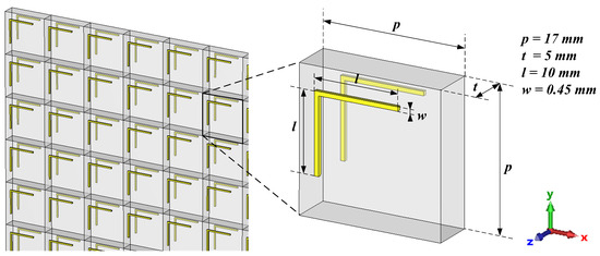
Figure 1.
Schematic diagrams of the sample and unit cell. The dimensions of the fabricated prototype are also shown.
To the best of our knowledge, this is one of the few transmission-mode metasurfaces to achieve over 25% relative bandwidth while maintaining a compact dual-layer design and mechanical reconfigurability. The proposed metasurface exhibits three distinct LTC polarization conversion bands. In this work, we focus on the optimization of the resonator geometry and arrangement, employing full-wave electromagnetic simulations to maximize performance in the widest band. Experimentally validated results confirm a relative bandwidth of around 26% centered at 11.75 GHz, with an axial ratio (AR) below 3 dB, polarization conversion efficiency (PCE) up to 65%, and insertion losses below 1.3 dB. Furthermore, the mechanical rotation approach provides straightforward reconfiguration, robustness, and scalability, allowing straightforward adaptation across the microwave spectrum by geometric scaling of the resonator layout.
The remainder of the paper is structured as follows. Section 2 describes the design principles and optimization methodology for the proposed metasurface. Section 3 discusses simulation results, focusing on performance analysis. Experimental characterization and comparative analyses are presented in Section 4, confirming the simulated predictions. Finally, Section 5 summarizes the main findings.
2. Design and Operation of the Reconfigurable LTC Metasurface
The metasurface unit cell (Figure 2) consists of an L-shaped low-carbon steel wire resonator (AWG-25, 0.455 mm × 0.455 mm cross-section, 20 mm total length) mounted on a low-permittivity foam substrate.
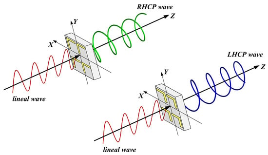
Figure 2.
Sample made of four unit cells (simulations makes use of a periodic arrangements) for LTC polarization conversion in the RHCP configuration (upper-left) and LHCP configuration (bottom-right), produced by mechanically rotating the slab by .
The L-shaped resonator was selected after evaluating other geometries, including U-, T-, and V-shaped structures. These more complex layouts can support circular polarization conversion by enabling excitation of orthogonal dipole components with the appropriate phase shift [24]. However, our goal was to identify the simplest structure capable of fulfilling this function while also providing the required 90º rotational symmetry for handedness switching. The L-shape proved to be the most effective compromise, offering both minimal structural complexity and the widest relative bandwidth among the configurations tested.
Three configurations were investigated:
- Single-layer: resonators on the front face of the foam slab.
- Dual-layer: identical resonators on both faces of the slab, aligned in the plane.
- Triple-layer: resonators on the three planes separated by foam slabs.
The foam substrate () was chosen to minimize dielectric loading, broaden the resonance, and simplify fabrication. While higher-permittivity materials could also be employed, they require tighter etching tolerances and thinner layers, which increase manufacturing complexity.
Numerical simulations have been carried out using an array of unit cells with periodic boundary conditions. Polarization reconfiguration is achieved by mechanically rotating the entire metasurface slab by 90° about the z-axis. This rotation swaps the alignment of the front and back resonators, inverting the sign of the phase difference between the orthogonal transmitted field components, thereby switching between RHCP and LHCP states without any active components.
In order to characterize the effect of the metasurface on the polarization behavior, we adopt standard electromagnetic parameters such as axial ratio (AR), polarization conversion efficiency (PCE), ellipticity, and insertion loss, following conventional formulations in [7,25].
We assume a time-harmonic plane wave propagating along the direction with linear polarization along : , where is the complex amplitude and k the wavenumber. After transmission, the field becomes
where denotes the transmission coefficient from polarization b at port 1 to polarization a at port 2.
Ideal LTC conversion requires
The axial ratio (AR) is calculated as [7]
Total transmittance T, reflectance R, and absorptance A are as follows:
Insertion loss (IL) is
The polarization conversion efficiency (PCE) is
Ellipticity, indicating polarization handedness, is defined as:
with corresponding to pure RHCP (+) or LHCP (−).
Right- and left-handed circular components are as follows:
Corresponding power fractions:
The polarization ellipse can be reconstructed using the following:
These expressions assume -polarized excitation. For arbitrary excitation, additional components would be involved.
A 90° mechanical rotation of the slab reverses the phase relation between and , inverting and switching circular polarization handedness. This effect is confirmed through full-wave simulations and experimental measurements.
3. Numerical Simulation and Performance Optimization
Full-wave simulations were performed using CST Studio Suite 2023® with the frequency-domain solver. A single unit cell was modeled with periodic boundary conditions applied along the x- and y-directions (transverse to propagation) to emulate an infinite array, and open (“add space”) boundary conditions in the z-direction. The structure was illuminated by a normally incident plane wave through waveguide ports. A tetrahedral mesh with adaptive refinement near the steel resonators ensured accurate capture of surface currents and fringing fields. The minimum mesh step was set to approximately 0.08 mm in the metal-dielectric regions, corresponding to about one-fifth of the resonator wire thickness. Additional local refinement was applied around the wire corners and substrate interfaces to improve phase accuracy. Convergence studies were carried out to ensure that variations in the computed S-parameters remained below 0.05 dB, balancing accuracy and computational load.
The foam substrate was modeled as a low-loss dielectric (, ), consistent with experimental characterization (see Section 4.3). Metallic elements were simulated using the bulk conductivity of low-carbon-steel ( S/m), as provided by the software’s default material library.
3.1. Design and Selection of the Prototype
Before building a prototype, a systematic comparison of single-, dual-, and triple-layer configurations was carried out under identical criteria to determine the most effective architecture. In all the cases, the size of L-shaped resonator was fixed (10.0 mm × 10.0 mm), and parametric sweeps of the pitch p were performed to maximize the bandwidth—using the AR < 3 dB criteria—for that specific layer count. The slab thickness t was held at 5 mm for single and dual layers, and 10 mm for the triple-layer case.
The performance parameters reported in Table 1, therefore, reflect the best-case results for each configuration, ensuring a fair benchmarking of their optimized capabilities. These results clearly demonstrate that the two-layer configuration provides the optimal trade-off among bandwidth, insertion loss, polarization conversion efficiency, and device compactness.

Table 1.
Results for single-, dual-, and triple-layer prototypes. Each configuration was independently optimized to maximize bandwidth.
The dual-layer design achieves a relative conversion bandwidth of 26%, significantly outperforming their single-layer (18%) and triple-layer (13%) counterparts under the criterion AR < 3 dB. This bandwidth enhancement arises from the coupling between the front- and back-face L-shaped resonators, which broadens the frequency range over which the amplitude and phase conditions for circular polarization are simultaneously satisfied. Moreover, the insertion losses for the dual-layer structure (between 0.1 and 1.3 dB) are markedly lower than those presented by the single-layer case (2.3–2.8 dB) and similar to the triple-layer case (0.2–1.2 dB). Such low IL values confirm efficient power transmission and minimal dissipative losses. In terms of PCE, the dual-layer metasurface delivers values ranging from 35% to 65%, compared to 40–45% for one layer and 34–60% for three layers, indicating that two layers are sufficient to achieve high conversion without the added complexity of a third resonator. Finally, the average AR within the conversion band is 1.9 dB for the two-layer device, lightly higher than 1.7 dB for three layers and lower than 2.1 dB for a single layer, in any case ensuring near-circular output polarization. Taken together, these results identify the two-layer metasurface as the configuration that maximizes operational bandwidth and conversion performance while minimizing IL. Therefore, the study of four or more layers was not pursued, as it would compromise the simplicity and scalability goals of the design.
As an example of the optimization process, Figure 3 shows the AR of the transmitted signal as the unit-cell lateral size, p, varies from 14 mm to 18 mm in 0.5 mm increments, with slab thickness fixed at 5 mm and a two-layer configuration. The curve for mm highlighted yields the maximum bandwidth of 26%. A finer sweep of 0.1 mm around this preliminary optimum confirmed convergence when the relative bandwidth variation fell below . Although a further refinement could increase the bandwidth, it would do so at the expense of a higher average AR.
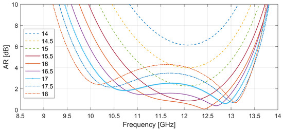
Figure 3.
Axial ratio at the main LTC conversion band for pitch size p sweeping from 14 mm to 18 mm.
Simultaneously, the slab thickness, t, was also varied to identify the optimum configuration for AR bandwidth. The best results were found for a substrate thickness from 5 mm to 10 mm.
3.2. Numerical Analysis of the Prototype
Figure 4 presents three key electromagnetic parameters used to quantify the polarization conversion performance of the selected design. We can observe that the cross-polarized transmission component is similar, in magnitude, to the co-polarized one between 10.2 GHz and 13.3 GHz (marked by vertical dashed lines). This fact, combined with the phase difference remaining close to , are the necessary conditions for CP.
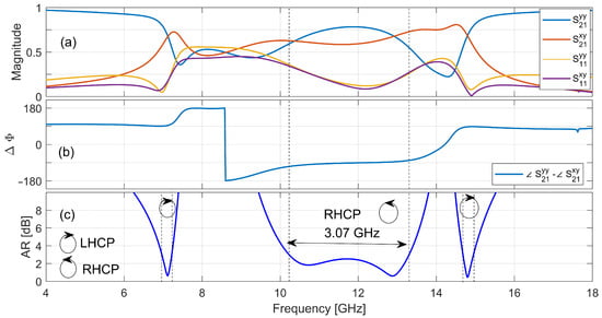
Figure 4.
Response of the optimized two-layer metasurface under normal incidence of a y-polarized plane wave. (a) Magnitudes of the S-parameters. (b) Phase difference . (c) Axial ratio (in dB). The optimized band ( dB) is marked by a double-headed arrow.
The AR remains below 3 dB across a 3.1 GHz bandwidth, with an average value of 1.95 dB, confirming an effective LTC conversion. Additional regions around 7.1 GHz and 14.8 GHz also show LTC behavior in narrower frequency bands (0.25 GHz and 0.27 GHz, respectively) that were not optimized in this work.
Figure 5 summarizes the energy balance and conversion performance. Within the 10.2 GHz to 13.3 GHz LTC conversion band, the metasurface exhibits a total transmittance greater than , a reflectance below and quite low absorption levels (<). These values indicate acceptable power delivery through the structure, with limited back-reflection and dissipation. The IL remains below 1.3 dB throughout the band, which is consistent with the observed transmission efficiency and confirms the passive, low-loss nature of the device. The PCE ranges from to within the band of interest. While this value does not reach unity, it is sufficient to yield an AR < 3 dB. These results confirm that a significant portion of the transmitted energy is redirected into the desired circular polarization state.
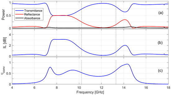
Figure 5.
Energy and conversion performance: (a) Transmittance, reflectance, and absorptance. (b) Insertion loss (dB). (c) Polarization conversion efficiency .
Figure 6 provides a comprehensive analysis of the polarization characteristics of the transmitted signal in the circular basis. Within the conversion band, the RHCP component dominates, with values ranging from 0.85 to 0.97, while the LHCP component remains below . This indicates high directional selectivity for RHCP. This is further confirmed by a RHCP projected fraction, , larger than 0.97 throughout the band, whereas remains below 0.03. In contrast, for the two other secondary LTC conversion layers, centered at 7.1 GHz and 14.8 GHz, the structure exhibits a directional selectivity for LHCP. The ellipticity remains near across the entire operating band, which confirms not only that the transmitted field is polarized in the RHCP state, but also that the polarization is close to purely circular. Taken together, these three plots demonstrate that the metasurface operates as an effective RHCP polarizer over the specified frequency range.
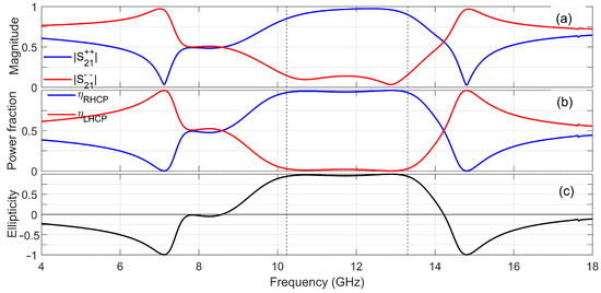
Figure 6.
Circular-basis performance: (a) Circular transmission magnitudes. (b) Power projection into RHCP/LHCP. (c) Ellipticity .
Figure 7 provides a visual reconstruction of the transmitted polarization ellipses at twelve representative frequencies, encompassing both those within and outside the main conversion band. Within the conversion band, the transmitted field is RHCP and presents a closed circular shape. In contrast, the LTC conversion band at 7 GHz is left-handed and also presents a quite circular shape with an AR of ≈0.6 dB. The plot for 8 GHz, between the first and second LTC bands, shows a LP transmitted wave rotated by ∼, indicating that the structure does not achieve circular conversion at this frequency. Finally, the plot for 18 GHz shows an almost LP wave aligned with the incident field.
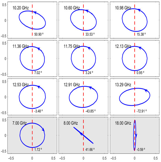
Figure 7.
Transmitted polarization ellipses at twelve representative frequencies: nine within the main LTC conversion band and three outside it (gray background). Each subplot overlays the incident linear polarization (red dashed line) and the transmitted field ellipse (blue), annotated with the frequency and polarization tilt angle.
3.3. Qualitative Physical Analysis of the LTC Conversion Mechanism
The linear-to-circular polarization (LTC) conversion can be understood by analyzing the surface currents induced in both resonators. Figure 8 shows the simulated current distributions in the front and back L-shaped resonators over a full oscillation cycle in the dual-layer prototype, and at the center of its polarization conversion frequency band, the result being very similar in the whole band. The directions of the currents in the second L-resonator (i.e., the resonator responsible for the transmitted signal) has been re-marked. It is interesting to note that this result, again, is virtually identical if we observe the single-layer structure or the last L resonator in the triple-layer structure.
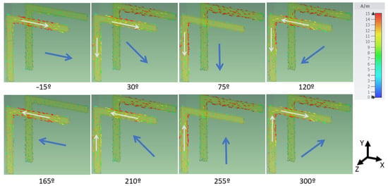
Figure 8.
Simulated surface current density on the dual L-shaped resonator structure over one oscillation cycle at 11.75 GHz. Each snapshot corresponds to an equally spaced phase instant. The incident wave, linearly polarized along the y-axis and propagates in the -direction, excites the back resonator, while the transmitted field emerges from the front resonator.
The incident wave is linearly polarized along the y-axis and propagates in the -direction, first interacting with the back resonator.
It is noteworthy that although the incident electric field is aligned with the vertical (y-oriented) arm, the strongest surface currents in the back resonator are observed in the horizontal (x-aligned) segment. This indicates that the structure favors a resonant response in that direction, likely due to near-field coupling within the L-shape, as reported in previous studies, which show the resonance of an L resonator may be split into two coupled modes, one in each arm [24].
The induced fields then excite the front resonator. For ease of understanding, we represent the magnitude of the current vector in both arms with the help of a white arrow, and its vectorial sum (i.e., the total current) with a blue arrow in the center of the figure. We may observe that the current in both arms is lagged by approximately 90°, consistent with a capacitive coupling between both arms. The combination of two orthogonal transmitted field components—with nearly equal amplitude and 90° phase shift—leads to the generation of a counterclockwise rotation of the current vector, meaning the outgoing wave is an RHCP wave in the forward direction. This result being consistent with other linear to circular converters using different structures [15,18].
3.4. Discussion of Simulation Results
The simulation results confirm that the optimized two-layer achieves an efficient LTC polarization conversion in the 10.2–13.3 GHz band. Within this range, the amplitude and phase conditions required for RHCP transmission are simultaneously satisfied, yielding dB, high RHCP power content (), and normalized ellipticity . The energy-balance analysis further indicates low insertion losses (below 1.3 dB) and minimal absorption, demonstrating that the structure operates passively with excellent impedance matching. The conversion efficiency peaks around 65% and remains above 35% across the band, which is sufficient to achieve nearly circular polarization due to the favorable phase shift between orthogonal field components.
From a structural standpoint, coupling between the front- and back-face resonators plays a critical role in broadening the operational bandwidth. Compared to single- and triple-layer designs, the two-layer configuration offers the best trade-off between bandwidth (26%), insertion loss, and device compactness, without the complexity and thickness penalty of an extra resonator layer. Secondary LTC bands at 7.1 GHz and 14.8 GHz, while narrower, underline the possibility of future multiband implementations by leveraging additional resonant pathways.
Table 2 presents a benchmarking of recent linear-to-circular polarization converters operating in the microwave regime, including both mechanically and electronically tunable designs. Only the widest conversion band is shown for multiband devices. As seen in the table, several designs achieve broader bandwidths—for instance, Fahad et al. [18] report up to 41% and Zeng et al. [26] reach 54%—but all of them lack handedness switching capabilities. Electronically reconfigurable converters [14,21,27] offer polarization control via electric fields in liquid crystals or PIN diodes, but they require external biasing networks and are generally limited in bandwidth and integration flexibility. Mechanically reconfigurable structures such as those in [23,26] present interesting alternatives, yet often involve more complex architectures (e.g., multilayered or 3D liquid–metal configurations) or are limited to frequency tuning only. In contrast, the proposed metasurface uniquely combines transmission-mode operation, passive mechanical switching between RHCP and LHCP, broadband performance (26% relative bandwidth), and a compact, dual-layer design. To the best of our knowledge, it is one of the few microwave-frequency metasurfaces offering handedness reconfiguration with such simplicity and efficiency.

Table 2.
Benchmarking of linear-to-circular polarization converters. Only one representative band is shown for multiband designs. TW: this work; T: transmission mode; R: reflection mode. * unit cell rotation/flipping, scissor spacing.
In addition to evaluating the nominal structure, we also explored its frequency scalability via geometric scaling. Figure 9 shows the axial ratio (AR) in dB for the optimized two-layer metasurface (blue line) and for geometrically scaled versions where all dimensions were increased and decreased by (red and black lines, respectively). The results confirm that the three main LTC resonance bands shift predictably with the resonator length and unit cell dimensions.
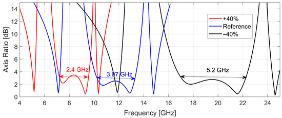
Figure 9.
Axial ratio versus frequency for the optimized two-layer metasurface (blue), and for uniformly scaled versions of the structure by +40% (red) and −40% (black).
For instance, scaling down the geometry by 40% shifts the main resonance band to the 17.0–22.2 GHz range while preserving a significant bandwidth of ≈5.2 GHz, corresponding to a relative bandwidth of 26%, consistent with the original design. On the other hand, scaling up the structure by +40% moves the band to 7.2–9.6 GHz. In this case, although the LTC response is preserved, the axial ratio slightly increases to 3.4 dB at the center frequency. These results confirm that the design can be straightforwardly retuned across the microwave spectrum by adjusting the geometrical parameters.
The unique mechanical switching capability of the presented design—uncommon among high-bandwidth transmissive converters—provides a significant competitive edge. By prioritizing simplicity, robustness, and low insertion loss through passive mechanical rotation, this metasurface occupies a distinct niche compared to the prevailing trend of complex, electronically reconfigurable architectures. For applications where rapid tuning is not essential—such as fixed-configuration satellite communications, long-duration remote sensing, or power-constrained embedded systems—this approach offers a superior trade-off in terms of cost, reliability, and energy efficiency.
4. Experimental Validation and Discussion
4.1. Measurement Set-Up
To validate the simulated performance, the optimized prototype was fabricated and characterized by using a free-space set-up following the procedure described in [28]. The sample consists of a array of resonators, with a total area of 234 cm2, and is sufficiently large to minimize edge diffraction effects [29]. Each unit cell includes AWG25 low-carbon-steel wire resonators placed on both faces of a 5 mm thick foam slab (measured permittivity over the band).
The prototypes were fabricated by manually gluing AWG25 wires onto both faces of the foam slab. The wires were pre-bent to 90° and cut to precise lengths using a digital lathe. To ensure accurate positioning and alignment, both surfaces of the foam were marked using a computer-controlled milling tool. This procedure minimized assembly errors and improved the structural symmetry in the dual-layer configuration.
The measurement set-up used dual-polarized horn antennas for both transmission and reception, enabling independent measurement of the x and y field components. To minimize diffraction and spillover, an ellipsoidal reflector was employed to focus the incident beam onto the sample. The transmitting horn was placed at one focal point of the reflector and the sample at the other [29]. The receiving horn was positioned co-focally on the opposite side, with its polarization axis orthogonal to that of the transmitter to facilitate cross-polarization measurements. Figure 10 shows a photograph of the measurement set-up and a schematic of the unit cell.
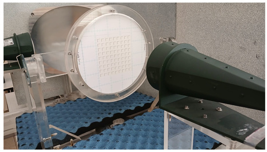
Figure 10.
Photograph of the experimental set-up.
S-parameters (, , and ) were recorded using a vector network analyzer. Time-domain gating [30] was applied to the measured data to suppress antenna mismatch ripples, edge diffraction, and unwanted multiple reflections from the mirror–sample–antenna system. Although the focused beam resembles a Gaussian profile, previous studies have shown that the standard plane-wave retrieval algorithm introduces only a negligible error under these conditions [28].
To switch between RHCP and LHCP configurations, the sample was manually rotated by 90° around its normal (z-) axis between measurements.
4.2. Experimental Results
Figure 11 compares the simulated and measured performance of the optimized two-layer metasurface in both RHCP and LHCP configurations. Overall, the experimental results closely match the key features predicted by full-wave simulations, with two clearly distinct resonant bands with AR < 3 dB. An expected band near 7.1 GHz appears at the lower edge of the experimental frequency range; however, our experimental set-up was unable to resolve it. The main resonance band is downshifted, found to be between 9.7 GHz and 12.8 GHz for the RHCP configuration and between 9.6 GHz and 12.2 GHz for the LHCP configuration. In contrast, the third resonance band exhibits a light upward shift, occurring at 15.2 GHz and 15.1 GHz, for the RHCP and LHCP configurations, respectively.
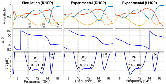
Figure 11.
Simulated and measured responses for the RHCP and LHCP configurations. The first column reproduces Figure 4, but limited to the measured band. Rows from top to bottom: magnitudes of , , and ; phase difference ; and AR (in dB).
The phase difference plots confirm the expected polarity inversion upon rotating the sample by : the sign of reverses across the entire band, verifying robust mechanical switching between right- and left-handed circular polarization. The frequency offsets are attributed to fabrication tolerances in wire dimensions, variations in substrate permittivity, and slight misalignments in the free-space measurement set-up. Despite these shifts, the measured axial ratios remain below 3 dB over the shifted bands, demonstrating that the metasurface’s design principles translate effectively from simulation to experiment.
Figure 12 compares the circular-basis response of the optimized two-layer metasurface in its RHCP (left column) and LHCP (right column) configurations. As expected, for the RHCP configuration dominates within the conversion band, with and . Upon rotating the sample by , this behavior is reversed: the LHCP component () becomes the stronger, with and . The excellent agreement between these measurements and the simulated trends (Figure 6) confirms that mechanical rotation offers a robust, passive method to switch the handedness of the transmitted circular polarization.
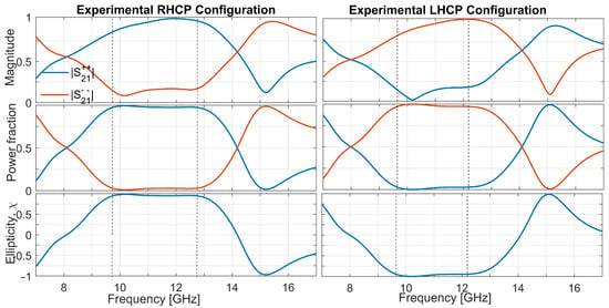
Figure 12.
Circular-basis performance of the optimized two-layer metasurface obtained from experiment. From top to bottom: and ; power projection onto RHCP/LHCP; ellipticity .
The experimental circular-basis results demonstrate that the dual-layer metasurface not only achieves high RHCP conversion in its default orientation, but also reliably switches to LHCP when mechanically rotated by . Minor deviations in the absolute levels of and (on the order of 2–3%) arise from fabrication tolerances in wire alignment and substrate properties, as well as residual reflections in the free-space set-up. Nevertheless, the ellipticity remains within across the main conversion band, underscoring the design’s efficacy and repeatability. These results validate the metasurface’s application potential for passive, switchable polarization control in microwave systems.
4.3. Discussion of Experimental Results
The experimental measurements closely validate the simulated predictions for the optimized dual-layer metasurface (Table 3). The main LTC conversion band is observed between 9.7 and 12.8 GHz in the RHCP configuration, preserving the simulated 26% relative bandwidth, and between 9.6 and 12.2 GHz in the LHCP configuration, corresponding to a slightly narrower 24% bandwidth.

Table 3.
Simulation vs. Experimental results for key parameters.
We attribute these modest discrepancies—and the small RHCP/LHCP bandwidth asymmetry—to manual assembly tolerances, including the following: (i) mm misalignment between two L-shaped layers, (ii) local variations (<5%) in the foam permittivity, and (iii) uncertainties in the free-space collimation.
The measured center frequencies show downward shifts of approximately 4% and 7% for the RHCP and LHCP configurations, respectively, relative to the simulated center frequency 11.77 GHz. A further 3% offset ( GHz) is observed between the two experimental configurations themselves. These deviations are consistent with the aforementioned fabrication and material tolerances. Notably, the mechanical rotation required for handedness switching exposes different regions of the sample, potentially revealing local nonuniformities such as slight variations in wire placement or adhesive. Furthermore, frequency deviations in the range of 4–7% are commonly reported in experimental metasurface studies—even when standard industrial fabrication techniques are employed.
Despite these offsets, the AR remains below 3 dB across both measured bands, confirming robust circular polarization conversion.
Because the resonance is governed mainly by inter-layer coupling, we expect that standard manufacturing techniques—where layer registration is routinely better than ±50 μm—could potentially restore LHCP performance to the 26% bandwidth predicted by simulation. However, adapting the current prototype to industrial fabrication would require taking into account the dielectric properties and thickness constraints of commercial PCB materials.
The measured IL stays below 2.5 dB in both orientations, in line with the simulated values, indicating low dissipative losses and efficient power transmission. Furthermore, the polarization conversion efficiency ranges from 0.35 to 0.6, slightly lower than the simulated 0.40–0.65, yet sufficient to maintain an average AR of approximately 2.3 dB.
Circular-basis analysis confirms passive handedness switching: in the RHCP orientation, and ellipticity , while in the LHCP configuration, and . These results underscore the effectiveness of mechanical rotation as a low-loss reconfiguration mechanism.
Overall, the experimental findings demonstrate excellent agreement with full-wave simulations, validating the design methodology and confirming the metasurface’s potential for practical, switchable linear-to-circular polarization conversion in the frequency band. The structure was specifically optimized for normal incidence, where its broadband performance is maximized. Additional full-wave simulations suggest that acceptable LTC behavior is maintained for small deviations from normal incidence (up to approximately ), although polarization purity degrades beyond this range.
5. Conclusions
This study presents a mechanically reconfigurable two-layer metasurface that achieves broadband LTC polarization conversion. The main results are as follows:
- A mechanical rotation of the slab switches the transmitted wave between RHCP and LHCP without bias networks or active components.
- The dual-layer L-shaped topology provides a relative bandwidth of with an axial ratio below 3 dB and insertion loss under 1.3 dB in the RHCP orientation.
- In the LHCP orientation, the bandwidth narrows to ; this reduction is due to manual assembly tolerances, and the full is expected to be recovered with standard industrial fabrication.
- The metasurface reaches a polarization conversion efficiency of up to 65% and an ellipticity , confirming robust circular polarization.
- Since the resonance frequency mainly scales with resonator length and unit-cell dimensions, the design can be retuned across microwave bands through straightforward geometric scaling.
Beyond these quantitative parameters, the converter relies on an extremely simple resonator geometry. To the best of our knowledge, it is among the simplest transmissive metasurfaces reported to date, combining broadband LTC conversion with mechanical handedness switching. Its structural minimalism favors low-cost fabrication and high reliability.
The rotation concept could, in principle, be extended to other shaped or asymmetric resonators described in the literature. Exploring such generalizations, and assessing their bandwidth, efficiency, and fabrication tolerances, constitutes a promising avenue for future research.
Author Contributions
Conceptualization: G.J.M.-C., Á.J.G.-C., I.B., and J.M.; Methodology: G.J.M.-C., Á.J.G.-C., and J.M.; Numerical simulations: Á.J.G.-C. and I.B.; Code and programming: G.J.M.-C.; Measurements: G.J.M.-C. and Á.J.G.-C.; Writing—original draft preparation: G.J.M.-C. and Á.J.G.-C.; Experimental set-up: J.M.; Writing—review and editing: all the authors; Project administration: I.B.; funding acquisition: all the authors. All authors have read and agreed to the published version of the manuscript.
Funding
This research was funded by the Spanish Ministry of Science and the European Union: MCIN/AEI/10.13039/501100011033/FEDER, UE, grant number PID2022-137619NB-I00.
Data Availability Statement
Research data contained within the article are available upon reasonable request.
Conflicts of Interest
The authors declare no conflicts of interest.
References
- Ni, X.; Emani, N.K.; Kildishev, A.V.; Boltasseva, A.; Shalaev, V.M. Broadband Light Bending with Plasmonic Nanoantennas. Science 2013, 335, 427. [Google Scholar] [CrossRef]
- Chen, H.-T.; Taylor, A.J.; Yu, N. A Review of Metasurfaces: Physics and Applications. Rep. Prog. Phys. 2016, 79, 076401. [Google Scholar] [CrossRef]
- Khan, M.I.; Khalid, Z.; Tahir, F.A. Linear and Circular-Polarization Conversion in X-Band Using Metasurface. Sci. Rep. 2019, 9, 4552. [Google Scholar] [CrossRef] [PubMed]
- Zhang, X.; Ye, H.; Zhao, Y.; Zhang, H. Linear-to-Circular Polarization Converter with Adjustable Bandwidth Realized by the Graphene Transmissive Metasurface. Plasmonics 2022, 17, 1079–1089. [Google Scholar] [CrossRef]
- Zafar, J.; Khan, H.Z.; Jabbar, A.; Kazim, J.u.R.; Imran, M.A. Multi-Band Reflective Metasurface for Efficient Linear and Circular Polarization Conversion. Opt. Quant. Electron. 2025, 57, 149. [Google Scholar] [CrossRef]
- Wang, H.B.; Cheng, T.J.; Chen, Z.N. Wideband and Wide-Angle Single-Layered-Substrate Linear-to-Circular Polarization Metasurface Converter. IEEE Trans. Antennas Propag. 2020, 68, 1186–1191. [Google Scholar] [CrossRef]
- Balanis, C.A. Antenna Theory: Analysis and Design, 4th ed.; Wiley: Hoboken, NJ, USA, 2016. [Google Scholar]
- Hu, J.; Bandyopadhyay, S.; Liu, Y.H.; Shao, L.Y. A Review on Metasurface: From Principle to Smart Metadevices. Front. Phys. 2020, 8, 586087. [Google Scholar] [CrossRef]
- Zhang, Z.; Shi, H.; Wang, L.; Chen, J.; Chen, X.; Yi, J.; Zhang, A.; Liu, H. Recent Advances in Reconfigurable Metasurfaces: Principle and Applications. Nanomaterials 2023, 13, 534. [Google Scholar] [CrossRef]
- Majeed, A.; Zhang, J.; Ashraf, M.A.; Memon, S.; Mohammadani, K.H.; Ishfaq, M.; Sun, M. An Ultra-Wideband Linear-to-Circular Polarization Converter Based on a Circular, Pie-Shaped Reflective Metasurface. Electronics 2022, 11, 1681. [Google Scholar] [CrossRef]
- Hafeez, S.; Yu, J.; Umrani, F.A.; Yun, W.; Ishfaq, M. A Multiband and Multifunctional Metasurface for Linear and Circular Polarization Conversion in Reflection Modes. Crystals 2024, 14, 266. [Google Scholar] [CrossRef]
- Hayat, B.; Zhang, J.; Majeed, A.; Ishfaq, M.; Khan, A.; Ahmad, S. A low profile wideband linear to circular polarization converter metasurface with wide axial ratio and high ellipticity. Electronics 2022, 11, 352. [Google Scholar] [CrossRef]
- Zheng, Q.; Guo, C.; Ding, J. Wideband Metasurface-Based Reflective Polarization Converter for Linear-to-Linear and Linear-to-Circular Polarization Conversion. IEEE Antennas Wirel. Propag. Lett. 2018, 17, 1459–1463. [Google Scholar] [CrossRef]
- Wang, X.; Tong, L.; Chen, P.; Liu, L.; Yin, Y.; Zhang, H. A Multiband Dual Linear-to-Circular Polarization Conversion Reflective Metasurface Design Based on Liquid Crystal for X-Band Applications. Appl. Sci. 2025, 15, 8499. [Google Scholar] [CrossRef]
- Fahad, A.K.; Ruan, C.; Chen, K. Dual-Wide-Band Dual Polarization Terahertz Linear to Circular Polarization Converters Based on Bi-Layered Transmissive Metasurfaces. Electronics 2019, 8, 869. [Google Scholar] [CrossRef]
- Serebryannikov, A.E.; Lakhtakia, A.; Ozbay, E. Thermally switchable, bifunctional, scalable, mid-infrared metasurfaces with VO2 grids capable of versatile polarization manipulation and asymmetric transmission. Opt. Mater. Express 2022, 12, 4594–4605. [Google Scholar] [CrossRef]
- Zhao, J.; Song, J.; Xu, T.; Yang, T.; Zhou, J. Controllable Linear Asymmetric Transmission and Perfect Polarization Conversion in a Terahertz Hybrid Metal–Graphene Metasurface. Opt. Express 2019, 27, 9773–9781. [Google Scholar] [CrossRef]
- Fahad, A.K.; Nazir, R.; Ruan, C. Simple Design of Broadband Polarizers Using Transmissive Metasurfaces for Dual Band Ku/Ka Band Applications. Sensors 2022, 22, 9152. [Google Scholar] [CrossRef]
- Zhang, J.-J.; Xu, W.-X.; Zhao, Y.-T.; Xie, H.-Y.; Zu, H.-R.; Wu, B. Low Profile Dual-Band Polarization Conversion Metasurface with Omnidirectional Polarization. Materials 2023, 16, 4347. [Google Scholar] [CrossRef]
- Lor, C.; Phon, R.; Lim, S. Reconfigurable Transmissive Metasurface with Scissor and Rotation Actuators for Independent Beam Scanning and Polarization Conversion. Microsyst. Nanoeng. 2024, 10, 40. [Google Scholar] [CrossRef]
- Sofi, M.A.; Saurav, K.; Koul, S.K. A linear to circular polarization reconfigurable converter based on frequency selective surface. Microw. Opt. Technol. Lett. 2021, 63, 1425–1433. [Google Scholar] [CrossRef]
- Zhao, Y.; Liu, Z.; Li, C.; Jiao, W.; Jiang, S.; Li, X.; Duan, J.; Li, J. Mechanically Reconfigurable Metasurfaces: Fabrications and Applications. Npj Nanophotonics 2024, 1, 16. [Google Scholar] [CrossRef]
- Li, L.; Li, Y.; Wu, Z.; Huo, F.; Zhang, Y.; Zhao, C. Novel polarizationreconfigurable converter based on multilayer frequency-selective surfaces. Proc. IEEE 2015, 103, 1057–1070. [Google Scholar] [CrossRef]
- Liu, J.; Zhou, Q.; Shi, Y.; Zhao, X.; Zhang, C. Study of L-shaped resonators at terahertz frequencies. Appl. Phys. Lett. 2013, 103, 241911. [Google Scholar] [CrossRef]
- Jackson, J.D. Classical Electrodynamics, 3rd ed.; Wiley: New York, NY, USA, 1999. [Google Scholar]
- Zeng, L.; Zhang, H.-F.; Liu, G.-B.; Huang, T. A Three-Dimensional Linear-to-Circular Polarization Converter Tailored by the Gravity Field. Plasmonics 2019, 14, 1347–1355. [Google Scholar] [CrossRef]
- Cheng, Y.; Dong, Y. A High Efficiency Electrically Reconfigurable Circular Polarizer and Its Array Application. IEEE Antennas Wirel. Propag. Lett. 2021, 20, 2314–2318. [Google Scholar] [CrossRef]
- Margineda, J.; Molina-Cuberos, G.J.; Núñez, M.; García-Collado, A.J.; Martín, E. Electromagnetic Characterization of Chiral Media. In Solutions and Applications of Scattering, Propagation, Radiation and Emission of Electromagnetic Waves; Intech: London, UK, 2012. [Google Scholar] [CrossRef]
- Rojo, M.; Muñoz, J.; Molina-Cuberos, G.J.; García-Collado, A.J.; Margineda, J. Design of an Ellipsoidal Mirror for Freewave Characterization of Materials at Microwave Frequencies. Meas. Sci. Technol. 2016, 27, 035001. [Google Scholar] [CrossRef]
- Arsenovic, A.; Hillairet, J.; Anderson, J.; Forstén, H.; Rieß, V.; Eller, M.; Sauber, N.; Weikle, R.; Barnhart, W.; Forstmayr, F. scikit-rf: An Open Source Python Package for Microwave Network Creation, Analysis, and Calibration [Speaker’s Corner]. IEEE Microw. Mag. 2022, 23, 98–105. [Google Scholar] [CrossRef]
Disclaimer/Publisher’s Note: The statements, opinions and data contained in all publications are solely those of the individual author(s) and contributor(s) and not of MDPI and/or the editor(s). MDPI and/or the editor(s) disclaim responsibility for any injury to people or property resulting from any ideas, methods, instructions or products referred to in the content. |
© 2025 by the authors. Licensee MDPI, Basel, Switzerland. This article is an open access article distributed under the terms and conditions of the Creative Commons Attribution (CC BY) license (https://creativecommons.org/licenses/by/4.0/).