Abstract
Enhancing the failure tolerance ability of networks is crucial, as node or link failures are common occurrences on-site. The current fault tolerance schemes are divided into reactive and proactive schemes. The reactive scheme requires detection and repair after the failure occurs, which may lead to long-term network interruptions. The proactive scheme can reduce recovery time through preset backup paths, but requires additional resources. Aiming at the problems of long recovery time or high overhead of the current failure tolerance schemes, the Polymorphic Network adopts field-definable network baseline technology, which can support diversified addressing and routing capabilities, making it possible to implement a more complex and efficient failure tolerance scheme. Inspired by this, we propose an efficient Multi-topology Failure Tolerance mechanism in Polymorphic Network (MFT-PN). The MFT-PN embeds a failure recovery function into the packet processing logic by leveraging the full programmable characteristics of the network element, improving failure recovery efficiency. The backup path information is pushed into the header of the failed packet to reduce the flow table storage overhead. Meanwhile, MFT-PN introduces the concept of multi-topology routing by constructing multiple logical topologies, with each topology adopting different failure recovery strategies. Then, we design a multi-topology loop-free link backup algorithm to calculate the backup path for each topology, providing extensive coverage for different failure scenarios. Experimental results show that compared with the existing strategies, MFT-PN can reduce resource overhead by over 72% and the packet loss rate by over 59%, as well as effectively cope with multiple failure scenarios.
1. Introduction
With the continuous development of network technologies and applications, especially the widespread deployment of big data, cloud computing, and artificial intelligence, these industries, such as the Internet of Things (IoT), smart cities, autonomous driving, and telemedicine, are rapidly advancing. As a result, the demand for network traffic has grown exponentially, and network protocols and structures have become increasingly complex [1]. In the era of human–machine–object interconnectivity, the traditional TCP/IP-based internet architecture, with its single-carrier structure and unified routing mechanisms, suffers from many shortcomings, such as limited capability, weak security, and poor mobility, making it difficult to meet the future demands of diversified and specialized services [2]. As a forward-looking and diversified network paradigm, the Polymorphic Network aims to accommodate the deep integration needs of human–machine–object interconnectivity and allows the creation of different application network systems (i.e., network modalities) on the same network infrastructure, greatly promoting the integration of critical network applications with high reliability requirements, such as autonomous driving, augmented/virtual reality, and telemedicine [3]. Meanwhile, this also puts forward higher requirements for the network performance and reliability of the network architecture itself. Hence, enhancing the failure tolerance of Polymorphic Network has become a key issue for network operators to manage and maintain their networks.
Although various network technologies have been designed to improve the technical shortcomings of the traditional internet, the research on failure tolerance mechanisms for nodes and links in the network is still limited. Over the past decade, the link speed in data centers has increased from 1 Gbps to 100 Gbps [4]. While link speeds have continuously improved, the robustness of the network has not been effectively enhanced. Studies [5] show that large-scale networks, such as data centers and wide-area networks, contain hundreds or even thousands of switches and connections, and various failures from nodes and links are common network failure events. For instance, in Microsoft’s data center wide-area network, the probability of at least one link failure occurring every 10 min is as high as 30%. Facing the diversified network environment in the future, the complexity and uncertainty of networks make their security and reliability highly challenging. When network nodes or links are attacked or encounter uncertain threats, it leads to a significant loss of packets, interruption of related network services, and seriously affects the quality of service. Although Software-Defined Networking (SDN) greatly enhances network management and control capabilities, these issues with node and link failures still persist, and failure recovery mechanisms still face issues such as inefficiency or high recovery costs [6]. Therefore, facing the complex network environment with frequent failures in the future, enhancing the failure tolerance ability of the network to ensure that packets can still be forwarded normally during network failures, has become an important research topic in both industry and academia [7].
As a new network development paradigm, the Polymorphic Network adopts field-definable network baseline technology to support various addressing and routing strategies such as content identification [8], geospatial identification [9], identity identification [10], and custom identifiers, making the network’s functional forms flexible and efficient in adapting to complex and changing diverse demands [11]. Meanwhile, the Polymorphic Network inherits the concept of control and forwarding separation and leverages the field-definable characteristic to enable more complex functions at the data layer, enabling centralized control of networks at flow units, also addressing network events at a finer packet-level granularity, which provides ample room for innovation in the development of network technology systems and their applications.
Hence, we leverage the unique network architecture and technological advantages of the Polymorphic Network to design an efficient Multi-topology Failure Tolerance Mechanism in Polymorphic Network (MFT-PN). The MFT-PN utilizes the fully programmable data layer and diverse routing capabilities in the Polymorphic Network to implement the collaboration of the control and data layer for achieving global control, granular state awareness, and distributed control capabilities. Specifically, the MFT-PN constructs multiple logical topologies to allow network devices to maintain multiple topologies instead of relying on a single topology for routing calculations, and adopts new failure processing logic to implement fast failure recovery at any network element to minimize packet loss, thus greatly enhancing the robustness of the network. Compared with traditional fault recovery mechanisms, the MFT-PN has the following advantages: (1) Combining centralized and distributed control: we implement intelligent routing decisions in the control layer to obtain optimal routing control. Meanwhile, in the data layer, we embed the failure recovery mechanism into the packet processing logic to respond to unexpected events such as node or link failures, greatly improving the efficiency of failure recovery. (2) Changing the backup path storage method: by utilizing the caching capabilities of Polymorphic Network elements, we store backup path information in registers instead of TACM. When a packet encounters a failure, the Polymorphic Network element pushes the backup path information as segment labels into the packet header, significantly reducing the resource overhead of the flow table. (3) Implementing a link-based backup path strategy: changing the traditional backup path strategies based on flows or terminals, we plan to calculate backup paths for each link to ensure that the flow table entries for backup paths are independent of the number of flows or hosts in the network, greatly improving the scalability of the failure recovery. Specifically, the main contributions of this paper include the following three aspects:
- We propose a Multi-topology Failure Tolerance Mechanism in a Polymorphic Network (MFT-PN). The MFT-PN utilizes the field-definable network baseline technology of Polymorphic Network to realize the packet processing logic with a failure recovery mechanism, guiding the fast path switching of flows encountering failures.
- We design a loop-free link backup algorithm based on multiple topologies in the control layer. By establishing multiple logical topologies for different network scenarios, we can reasonably select backup paths for different topologies and establish backup path tunnels for protection paths, which can achieve the network’s ability to recover from multiple failures.
- We conduct large-scale network simulations to verify the network performance of the MFT-PN. The experimental results show that the MFT-PN significantly reduces the packet loss rate while maintaining a low flow table storage resource overhead. Meanwhile, the MFT-PN can effectively handle multiple failure scenarios and improve the network’s robustness.
2. Related Works
The strategies for handling node or link failures can mainly be divided into reactive or proactive strategies. Reactive strategies work after failure occurs, and the main process is as follows: (1) the switch reports the failure to the controller, (2) the controller calculates the backup path based on the specific strategies, and (3) the controller updates the flow table entries in the relevant switches to guide the flow to the backup path [12]. During this process, the path calculation and the interaction between the controller and switches introduce significant delays. According to the literature [13], updating the flow table entries for a single switch can take 4 s in the worst-case scenario, which is unacceptable for delay-sensitive applications. Furthermore, the entire failure recovery process can lead to a large amount of packet loss, affecting network stability. To achieve faster failure recovery, proactive strategies calculate backup paths in advance and install them in the switches. Once the switch detects a failure, it can quickly switch the flow to the backup path. Although proactive strategies reduce failure recovery time by pre-installing backup paths in the switches, they consume additional flow table storage resources in the switches. Moreover, the Ternary Content Addressable Memory (TACM) commonly used in commercial switches is expensive, energy consuming, and has limited capacity [14]. Hence, in large-scale networks, the flow table entries of proactive strategies consume significant switch flow table storage resources, which cannot be ignored. Josbert et al. [15] considered heterogeneous service flows and their Quality of Service (QoS) requirements to propose a Dynamic Routing Protection Failure-Tolerance (DRP) mechanism. It reconfigures optimal disjoint routes based on network state changes and enables fast switching between routes. However, DRP has some limitations, such as additional memory consumption in the controller and increased network overhead due to frequent network state monitoring. Isyaku et al. [16] designed a backup path calculation method based on shortest paths, flow classification, and flow table resource utilization. It classifies flows based on protocol and implements various failure recovery strategies to reduce backup path flow table resource consumption. Haque et al. [17] combined the advantages of reactive and proactive strategies to propose a hybrid link failure recovery scheme called Revive to improve recovery delay and TACM usage. Revive constructs k-disjoint routing topologies to reduce backup switch delay and selects an appropriate topology in the controller to meet the application or service’s needs. However, Revive does not consider multi-failure scenarios. Yang et al. [18] proposed a failure recovery mechanism for SDN-IP hybrid networking. It reroutes flows to designated SDN switches for re-routing, but this approach causes congestion on related SDN switches. Csikor et al. [19] proposed Remote Loop-Free Alternate (rLFA) technology, a simple extension of LFA, in the case where each network link has a unit cost but is practically relevant. rLFA increases the coverage of fast protection for failure cases, but it cannot recover from some link failures where there is no overlap between P-space and Q-space. The comparison of typical failure recovery schemes is shown in Table 1.

Table 1.
Comparison of typical failure recovery schemes.
Based on the above analysis, the current failure recovery mechanisms either have a long recovery time or result in high recovery costs. These schemes usually cannot handle multiple failure situations. In contrast to previous works, our work in this paper utilizes the field-definable network baseline technology based on Polymorphic Network architecture to embed the failure recovery logic into the network element and implements the link backup path strategy based on the global network view to ensure low flow table storage resource overhead and significantly improve the ability to handle multiple failures.
3. Polymorphic Network Environment
3.1. Polymorphic Network Architecture
Polymorphic Network architecture adopts the concept of control and forwarding separation to integrate the traditional seven-layer network model into a three-layer structure consisting of the data layer, control layer, and service layer with full-dimensional definable functionality [20], as shown in Figure 1.
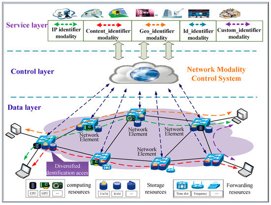
Figure 1.
Polymorphic Network architecture.
The data layer of the Polymorphic Network consists of network elements with full-dimensional, definable functionality and various heterogeneous resources. Network elements support the dynamic addition or removal of various network technologies in the form of modalities, and support hybrid access and collaborative processing of multiple heterogeneous identifiers. These heterogeneous resources include computing resources, storage resources, transmission resources, etc., which are encapsulated into different formats and provide an integrated representation and scheduling interface for the upper layers.
The control layer of the Polymorphic Network is composed of the network modality control system. The network modality control system implements polymorphic addressing and routing decisions to realize intelligent scheduling of underlying heterogeneous resources. It is responsible for implementing different modality management, developing different addressing and routing decisions, and forming resource scheduling methods for various network applications in the upper layer.
The service layer of the Polymorphic Network is designed to meet diversified service scenarios and network usage requirements. It adopts service dynamic orchestration and business adaptive bearing technologies and maps diverse and personalized business demands to different network identifier modalities. As a result, it also supports the development and application of new, custom identifier modalities.
3.2. Polymorphic Network Structural Model
The Polymorphic Network breaks through the traditional Internet’s single IP-based carrying structure, achieving the coexistence and collaborative development of multiple network modalities within the same network infrastructure. Figure 2 shows the Polymorphic Network structure model. Through the heterogeneous resource foundation and field-definable network baseline technology, the Polymorphic Network creates an open environment where multiple network modalities can coexist. The Polymorphic Network decouples the network technology system (network modalities) from the physical platform (network environment), allowing diverse upper-layer network applications to choose the corresponding network modality according to business needs. As a result, the Polymorphic Network fully utilizes the inherent characteristics of various network modalities and supports the coexistence, evolution, or transformative development of each network modality within the Polymorphic Network environment.
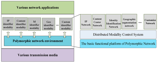
Figure 2.
Polymorphic Network structure model.
The field-definable network baseline technology is the foundation for the Polymorphic Network, enabling the coexistence of multiple network technologies (modalities) within the same physical infrastructure. The Polymorphic Network satisfies the underlying resource needs of various network modalities by deploying heterogeneous resources such as computing, storage, and transmission at the lower layer. To meet diverse transmission demands, the Polymorphic Network breaks the rigid system structure of traditional internet and decomposes traditional network functions and protocol stacks into finer-grained basic network functions. These basic network functions can be combined and scheduled to form more complex network functions, thereby satisfying the requirements of different network applications. These finer-grained basic network functions are referred to as “network baseline capabilities,” and diversified network functions can be formed by the combination and scheduling of these network baseline capabilities.
In the Polymorphic Network, network elements can process and forward packets based on custom packet formats, routing protocols, and switching methods by combining baseline capabilities. The traditional TCP/IP protocol stack is just a form of combining network baseline capabilities. According to network demands, network elements can simultaneously carry multiple instances formed by combining network baseline capabilities, providing diverse addressing and routing methods, as well as intelligent services. This approach fundamentally breaks through the traditional internet’s single IP-based carrying structure and addresses many of the existing internet’s shortcomings, such as low service efficiency, poor security, and mobility.
4. Design Concept of MFT-PN
The Polymorphic Network enables diverse addressing and routing capabilities with various identifier expressions, providing convenience for the integration of new network functions. Therefore, we focus on the multi-failure tolerance mechanism of the network, redefine the packet processing logic of network elements. Additionally, we change the storage method of backup paths, relying on the ubiquitous register caching capability of network elements to store the optimal backup path information for reducing the resource overhead of flow table storage. Below, we will describe the workflow of the MFT-PN.
4.1. Multi-Topology Failure Tolerance Architecture
The Polymorphic Network follows the principle of separating control and forwarding to enable centralized network control for implementing global optimization decisions based on the global network view. The data layer can provide more comprehensive and finer-grained network state information to the control layer; meanwhile, its pervasive computing and storage resources also allow us to perform more complex packet processing and storage operations, and offload part of the control logic to switch nodes for fast distributed control. As a result, the Polymorphic Network provides the network with greater resilience and offers new ideas for high-reliability routing in future complex and dynamic network environments.
The multi-topology failure recovery for Polymorphic Network is shown in Figure 3. By utilizing the fully programmable data layer and diverse routing capabilities in Polymorphic Network, we implement the collaboration of the control layer and data layer to achieve global control, granular state awareness, and distributed control capabilities to improve the overall service performance of the network. Specifically, the MFT-PN constructs multiple logical topologies and implements the fast-rerouting design to allow network devices to maintain multiple topologies instead of relying on a single topology for routing calculations. Even if one topology encounters issues, others will still function. Specifically, in the control layer, the MFT-PN generates multiple logical topologies based on the reliability requirements of diverse scenarios; each topology can have different routing strategies to provide different levels of failure recovery strategies for different business scenarios. In the data layer, we design the failure processing logic to implement failure recovery at any network element to minimize packet loss, thus greatly enhancing the robustness of the network. Through this approach, the MFT-PN significantly improves the protection coverage of traditional failure recovery technologies and is suitable for network environments that require high availability and low latency.
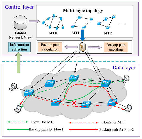
Figure 3.
Multi-topology Failure recovery for Polymorphic Network.
4.2. Failure Recovery Processing Logic
The MFT-PN leverages the definable characteristics of the Polymorphic Network element to extend the failure processing logic for nodes or links. The MFT-PN adopts failure processing logic in network elements at the data layer to execute failure recovery at any network node, minimizing packet loss and ensuring network reachability. Additionally, by adopting segment routing, the MFT-PN avoids differentiating between flow classification and modality protocol types, thus reducing TACM storage resource overhead.
To minimize the consumption of flow table TACM storage, Polymorphic Network elements encapsulate backup routing information into packet headers. Based on the backup path information in the packet header, the network element guides the flows to switch paths when encountering failures. The Polymorphic Network element uses different processing logic for fault and normal packets. The custom packet header format is shown in Figure 4. Here, the backup routing information is encapsulated before the modality protocol layer. The backup path information is independent of the specific network modality. When a failure occurs during the forwarding process, the Polymorphic Network element can activate the failure recovery mechanism and encapsulate the backup path information into the packet header to guide the failure recovery. Specifically, the Pkt_state field adds a failure indicator to distinguish between normal packets and those encountering link failures. A 32-bit Backup_path field is added to store the backup path information, with an 8-bit Path_ID representing the backup path identifier, a 7-bit Hop_count indicating the number of hops along the backup path, similar to the TTL field in the IP protocol. A 1-bit Flag indicates the stack bottom. If Flag = 1, it means this is the bottom label. The 16-bit Indicator field is used to indicate the network modality protocol used by the packet before the failure. When Indicator = 0 × 0800, 0 × 0809~0 × 081B, it represents packets corresponding to network modality protocols such as IPv4, IPv6, NDN, etc.
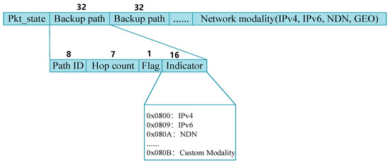
Figure 4.
Custom packet header format for failure recovery.
Figure 5 illustrates the failure recovery processing logic of the Polymorphic Network element. In the Polymorphic Network, network elements have pervasive caching capabilities. Here, the network element is equipped with two built-in registers. Register 1 is used to store the output port status table. The network element periodically detects the link status and stores the status information in Register 1. If the output port status is active, it indicates the link is normal, while inactive indicates a link failure. Register 2 is used to store the backup path information, which is pre-calculated by the controller based on the multi-topology backup path module and written to the register.
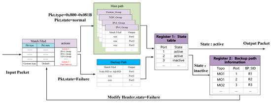
Figure 5.
The processing logic with failure recovery on Polymorphic Network element.
Since the packets encountering failures are much fewer compared to the vast amounts of network traffic, storing backup paths in registers instead of TACM memory can significantly alleviate the pressure on TACM storage resources. The network element applies different processing logic to packets based on the Pkt.type and Pkt.state values. If Pkt.type is 0 × 0800 or falls within 0 × 0809~0 × 081B, the packet is matched against the corresponding protocol modality and flow table entry to obtain the output port. After obtaining the output port, it will check the status information in Register 1. If the output port status is active, the packet is forwarded to the corresponding output port. If the output port status is inactive, the backup path is activated, and the backup path information is retrieved from Register 2. The network modality protocol identifier is assigned to the Indicator field, and the backup path information is encapsulated into the packet header. Then, the network element changes the Pkt.state value of the packet to 0 × 01, indicating the packet has encountered a link failure. The backup path information in the Backup_path field is used to re-enter the parser for re-parsing. At this point, the Pkt.state value is 0 × 01, indicating the packet is undergoing failure recovery. Then network element will loop the packet to the parser and match the backup path flow table entry based on the backup path information encapsulated in the packet header, and the path identifier BP_SID is used to obtain the corresponding backup path labels. After confirming the output port is normal, the packet is forwarded to the corresponding output port. If the output port is still not normal, the backup path information is re-encapsulated into the packet, and the matching process is repeated until the packet is forwarded normally. Once the packet bypasses the faulty link and reaches the downstream network element of the faulty link, the switch pops the backup path label, and the Model_ID value is modified according to the Indicator field to the original protocol modality value, indicating the packet has recovered to its normal state.
4.3. Multi-Topology Loop-Free Link Backup Algorithm
4.3.1. Network Model
Given a physical network , represents all node sets, represents all link sets, represents diverse logical topologies constructed based on the reliability requirements of different scenarios, and refers to the logical topology, excluding unreliable nodes and links. For logical topology , when a link fails, the traffic being transmitted on the link can be represented as , and represents the source and destination nodes of the flow , respectively. represents the bandwidth requirements of the flow . For the upstream and downstream nodes and of the link , the calculated P space of the upstream node is , and the calculated Q space of the downstream node is . For any path tunnel from P space to Q space, if is the backup path of the link , then , otherwise . Assuming the remaining bandwidth of the path tunnel is , the condition for to be the backup path of link is . Therefore, our optimization objective is to find the optimal path tunnel for balancing the link load. The optimization objective can be expressed as Equation (1), where is the maximum link load, and is the minimum link load.
4.3.2. Algorithm Design
Traditional failure recovery strategies generally implement failure recovery at the ingress switch, which inevitably leads to packet loss for faulty packets, severely impacting network service quality. The MFT-PN generates various logical topologies based on reliability requirements for different scenarios. Each topology can have different routing strategies, providing different levels of failure recovery tailored to specific business demands.
Based on this, we propose a loop-free link backup algorithm based on multi-topology. The algorithm addresses customized network topologies and reasonably selects backup paths for each link to establish backup path tunnels for protecting links and nodes. In case of a link or node failure, flows can quickly switch to the backup path and continue to forward, minimizing packet loss. Algorithm 1 shows the multi-topology loop-free link backup algorithm. The execution process of the algorithm is as follows: the input of the algorithm is the global network topology G(V,E), and the output is the backup path tunnel for all links of different topologies. Step 1 initializes the corresponding values , Steps 2~7 focus on reliability requirements for different scenarios and then combine node and link reliability to construct various logical topologies, such as the basic topology MT0 = G(V,E), excluding unreliable nodes or links MT1 = G(V − n,E) and MT2 = G(V,E − e), as well as other customized logical topologies MTn = G(V − n,E − e). Steps 8~21 are to iterate over each link to calculate backup paths and establish backup path tunnels for each topology. Specifically, in Steps 9~14, for the protected link, with the source node of the protected link as the root node, it removes the link and runs the SPF algorithm to calculate the P space P_space(), and with the destination of the protected link as the root node, it runs the SPF algorithm to calculate the Q space Q_space(). Then, it calculates the intersection of P space and Q space, and selects the optimal PQ node T as the best “transit” node for the protected link based on the link cost. Steps 15~19 are used to obtain the node and link labels of the optimal PQ node T, generate a label forwarding tunnel based on the backup path, and record it. Finally, the network element sends the backup path tunnel strategies to the data layer through the data–control interface for these strategies to take effect.
| Algorithm 1. Multi-Topology Loop-free Link backup algorithm |
| Input: Global network topology Output: Backup path tunnel of each link of different topologies (1) Initialization: ; (2) Based on the reliability requirements of different scenarios, to consider the reliability of nodes and links for constructing different logical topologies (3) MT0 = G(V,E);//Basic topology (4) MT1 = G(V − n,E);//Exclude node set n (5) MT2 = G(V,E − e);//Exclude link set e (6) ……; (7) MTn = G(V − n,E − e);//Customized Logic Topology (8) for each MT{1,…,n}: (9) for each in MTn://Traverse each link (10) ; (11) P_space() = SPF(, );//Calculate P space (12) Q_space() = SPF(, );//Calculate Q-space (13) ;//Calculate the intersection of PQ nodes (14) ;//Select the optimal PQ node as the transit node (15) ;//Obtain the node label of node T (16) ;//Obtain the adjacency label of node T (17) Backup_tunnel = Path_coding ();//Calculate backup path encoding (18) ;//Save the backup path tunnel into the set (19) Set_BPtunnel = install_table (Backup_tunnel, );//Install backup path table (20) end for (21) end for |
5. The Overhead Analysis
The overhead of MFT-PN is from two parts: the control layer and the data layer. The control layer deploys a centralized controller to maintain multiple logical topologies and calculate backup paths for each logical topology. For the controller, the overhead from maintaining multiple logical topologies and calculating backup paths for each logical topology, including computing and storage overhead. In actual networks, we assume that the centralized controllers will deploy sufficient computing and storage resources. Hence, this computing and storage overhead can be negligible for a centralized controller. The data layer runs on a fully programmable data plane infrastructure and requires certain flow table storage resources to store backup paths and network bandwidth to forward the packets. Assuming there are switches and links in the physical network, the logical topologies are , and their corresponding number of links is . Assuming that for each link in each logical topology, the number of backup paths is no more than 5 hops, the total number of flow tables for backup paths is . For the bandwidth overhead caused by custom packet headers, assuming there are flows in the network, the number of packet headers added by encoding in the backup path is 1~5. For each hop, the additional packet header field is 32 bits. Therefore, the bandwidth overhead caused by custom packet headers is bits.
6. Simulation Experiments
This section analyzes and verifies the performance of MFT-PN. Below are the descriptions of the experimental environment configuration, comparison schemes, and experimental results.
6.1. Experimental Setup
The experiment is conducted on the network simulation platform Mininet [21]. The data layer of the Polymorphic Network is composed of P4-16 BMv2 [22] switches, and the control layer is implemented using Python 3.11 scripts as the modality control system. We implement failure recovery logic on the P4-16 BMv2 switch using P4 language. The network topologies in the simulation are the wide-area Interllifiber topology (110 switches, 149 links) from the Internet Topology Zoo [23] and the fat-tree topology (80 switches, 256 links) applied in data center networks. During the simulation experiment, we use the iperf tool to generate TCP flows with varying sizes between nodes, and simulate link failures by randomly removing links using the Mininet command link down. The flow arrival rate follows the Poisson distribution, generating 100~400 flow/s.
6.2. Comparison Schemes
To validate the performance of MFT-PN, we compare it with the following baselines:
- Reactive (Reactive Failure Recovery) [12]: A reactive failure recovery strategy. When a packet encounters a link failure, the switch sends a failure message to the controller, and then the controller recalculates the path and updates the flow table to complete the failure recovery.
- OpenFlow-FF (OpenFlow-based Fast Failover) [14]: An active failure recovery strategy. It uses OpenFlow’s fast failover mechanism in the data plane to precompute backup paths for each flow and install them in the corresponding switches. The number of flow table entries for these backup paths is linearly related to the number of flows in the network, consuming a significant amount of flow table resources.
- IP-FRR (IP Fast Reroute) [19]: An active failure recovery strategy. This mechanism uses a loop-free alternate algorithm to calculate the backup next hop and pre-installs the loop-free backup next hop for each destination host in the switch. This failure recovery mechanism requires each switch to install backup paths for all hosts. However, when multiple failures occur, loops may still be created.
6.3. Simulation Results Analysis
(1) The number of flow table entries for the backup path
Figure 6 shows the flow table entries for backup paths under different traffic conditions. Since the reactive strategies occur after a failure happens, it does not require pre-installation of backup paths. Therefore, this experiment only considers proactive strategies. As shown in Figure 6, the curve of OpenFlow-FF grows rapidly as the number of flows increases. Since OpenFlow-FF needs to calculate a backup path for each flow individually, the total number of flow table entries for backup paths is linearly dependent on the number of flows. Hence, OpenFlow-FF may lead to very high flow table storage overhead, and even flow table overflow. IP-FRR requires each switch to store backup next-hop entries for all terminals. As a result, IP-FRR still installs many flow table entries to install backup paths, which results in large flow table storage overhead in large-scale networks. MFT-PN calculates loop-free backup paths for each link based on the multi-topology. Each switch only needs to install a small number of flow table entries to reroute all flows encountering the same failure. For MFT-PN, the number of flow table entries required is independent of the number of terminals and flows in the network. Hence, MFT-PN greatly reduces the flow table storage overhead while improving the network’s scalability.
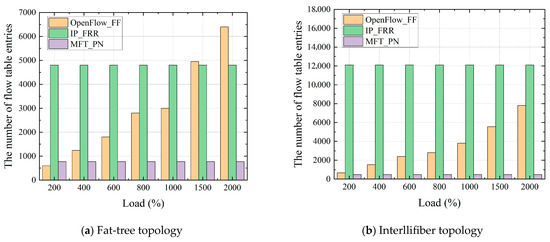
Figure 6.
The number of flow table entries for Backup Paths.
(2) Average packet loss rate of failure recovery
To analyze the performance of different schemes in handling link failures, this experiment injects flows into the network at varying rates, ranging from 0 to 1000 Mbps. In each round of the experiment, we simulate link failures by randomly removing links, and then record the packet loss rate for flows encountering link failures. Figure 7 shows the average packet loss rate of different strategies during failure recovery. As seen in Figure 7, the reactive strategy resulted in a significant amount of packet loss. This is because reactive strategies will cause a delay in interaction between the switch and the controller, as well as in recalculating the path, and cause a significant amount of packet loss. Among the three proactive strategies, the MFT-PN has the lowest packet loss rate. Since OpenFlow-FF only implements failure recovery at the ingress switch, packets encountering these failures are naturally discarded, leading to a higher packet loss rate. IP-FRR adopts the shortest path algorithm to calculate the backup next hop for all terminals. However, IP-FRR still has loops in the path calculation process and cannot cope with some multi-failure scenarios. The MFT-PN is a free-loop link-based backup path algorithm that adopts different backup path strategies for different logical topologies. When encountering link failures, the MFT-PN can quickly migrate traffic and guide flow to redirect to different backup paths, with minimal impact on network congestion. Therefore, the MFT-PN has the lowest packet loss rate.
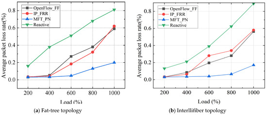
Figure 7.
Packet loss rate for failure recovery in different schemes.
(3) Multi-failure recovery capability
This experiment tests the multi-failure recovery capability of the MFT-PN. We construct three logical topologies (i.e., MT0, MT1, and MT2) for three types of service flows, with each logical topology using different backup path strategies. The failure recovery scenarios based on multi-topology are shown in Figure 8. During the experiment, we generate three service flows for each logical topology: for MT0, for MT1, and for MT2. We simulate link failures by randomly removing links and then record the path trajectory of traffic. During the experiment, we simulate the failure of physical links and . According to the backup path strategies calculated by the control layer for these three logical topologies, the paths for MT0, MT1, and MT2 are as follows: MT0: , MT1: , and MT2: . Figure 9, Figure 10 and Figure 11 show the path trajectory changes in three types of flows before and after the failures. As can be seen from Figure 8, Figure 9, Figure 10 and Figure 11, at time 0~T1, the original paths for three flows are , , , respectively, for MT0, MT1, and MT2. When the links and fail, the paths for the three flows quickly switch to new backup paths , and . It can be observed that MFT-PN effectively avoids loop issues when calculating backup paths, and three flows at the destination hosts , , and remain continuous. Furthermore, the path switch at times T1 and T2 happens with almost no delay, indicating that the flows can seamlessly switch paths. Therefore, MFT-PN’s multi-topology loop-free link backup path algorithm greatly improves the network’s ability to cope with multiple failures and maintains a lower failure recovery time.
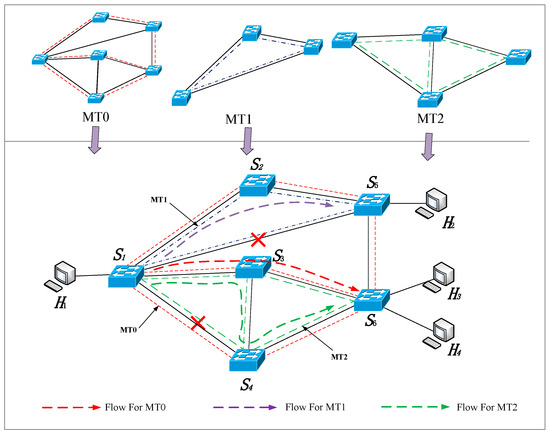
Figure 8.
Failure recovery scenarios based on multi-topology.
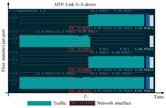
Figure 9.
The path trajectory of flow on MT0.
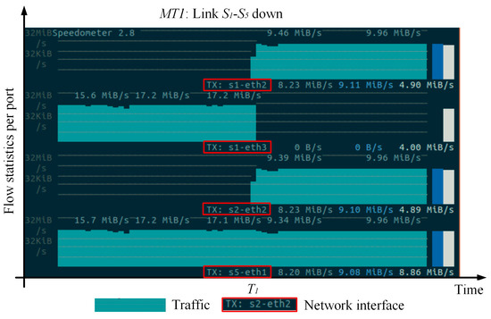
Figure 10.
The path trajectory of flow on MT1.
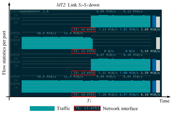
Figure 11.
The path trajectory of flow on MT2.
7. Discussion
How to detect failure in the MFT-PN: The MFT-PN focuses on how to efficiently recover from failure when failure occurs, but it does not address how to detect failure. In fact, it is more important to efficiently detect failure during the failure recovery process. One way to detect failure is for the switch to actively send link status heartbeat detection. If switch cannot receive detection packets from the neighboring switch , or if the link delay and the packet loss rate are too high, switch will determine that the link has failed.
The MFT-PN in Programmable Hardware: We implement the MFT-PN on the BMV2 switch in this paper. Although the BMV2 switch has similarities in programming implementation with programmable hardware, it is still insufficient to evaluate the performance of MFT-PN. As the next step of our work, we will implement the MFT-PN on programmable hardware and evaluate the resource overhead (i.e., register resources, flow table storage resources), packet resubmission latency, and switching latency of the MFT-PN.
Standardization of failure tolerance mechanism: The implementation of the MFT-PN demonstrates that the collaboration between the control plane and programmable data plane can achieve efficient failure recovery. However, the deployment of the MFT-PN in actual networks still faces many unresolved issues. For example, a standardized definition of backup path fields, backup path IDs management, including distribution and recycling of path IDs, etc.
8. Conclusions
The Polymorphic Network adopts field-definable network baseline technology to enable various network modalities to be processed in custom message formats, routing protocols, switching methods, forwarding logic, etc. In response to the low efficiency of current reactive strategies and the high cost of failure recovery of proactive strategies, we introduce the Polymorphic Network architecture and technical features, and propose an efficient multi-topology failure tolerance mechanism named MFT-PN. The MFT-PN utilizes the fully programmable capability of the data layer to embed a failure recovery function into the packet processing logic to enable network elements to quickly respond to node or link failures, ensuring the efficiency of failure recovery. Meanwhile, the MFT-PN adopts the caching capability of the Polymorphic Network to store backup path information. When a failure occurs, the network element pushes the backup path information in the form of segment labels into the packet header, greatly reducing the storage resource overhead of the flow table entry. Finally, we design a loop-free link backup algorithm based on multi-topology at the control layer. This algorithm generates multiple logical topologies based on the reliability requirements of diverse scenarios and provides different levels of failure recovery strategies for different network scenarios, greatly improving the network’s ability to cope with multiple failures. The experimental results show that the MFT-PN proposed in this paper ensures a lower failure recovery time, greatly reduces flow table storage resources overhead, and can effectively cope with scenarios where multiple failures occur simultaneously, greatly improving the robustness of the network.
Author Contributions
Conceptualization, Z.L. and B.L.; methodology, Z.L. and B.L.; software, W.J.; vali-dation, Z.L. and W.J.; formal analysis, Z.L., W.J. and L.T.; investigation, L.T.; validation, Z.L. and L.T. writing—original draft preparation, Z.L.; writing—review and editing, B.L. and L.T.; funding acquisition, Z.L. All authors have read and agreed to the published version of the manuscript.
Funding
The work has been supported by the National Natural Science Foundation of China under Grant 61872382.
Data Availability Statement
No new data were created or analyzed in this study. Data sharing is not applicable to this article.
Conflicts of Interest
The authors declare that they have no known competing financial interests or personal relationships that could have appeared to influence the work reported in this article.
References
- Jia, Z.; Cao, Y.; He, L.; Li, G.; Zhou, F.; Wu, Q. NFV-enabled service recovery in space-air-ground integrated networks: A matching game based approach. IEEE Trans. Netw. Sci. Eng. 2025, 12, 732–1744. [Google Scholar] [CrossRef]
- Islam, S.; Abdulsalam, A.Z.; Kumar, B.A.; Hasan, M.K.; Kolandaisamy, R.; Safie, N. Mobile networks toward 5G/6G: Network architecture, opportunities and challenges in smart city. IEEE Open J. Commun. Soc. 2024, 6, 3082–3093. [Google Scholar] [CrossRef]
- Wu, J.; Li, J.; Sun, P.; Hu, Y.; Li, Z. Theoretical Framework for a Polymorphic Network Environment. Engineering 2024, 39, 222–234. [Google Scholar] [CrossRef]
- Gill, P.; Jain, N.; Nagappan, N. Understanding Network Failures in Data Centers: Measurement, Analysis, and Implications. ACM SIGCOMM Comput. Commun. Rev. 2011, 41, 350–361. [Google Scholar] [CrossRef]
- Jin, X.; Li, Y.; Wei, D. Optimizing bulk transfers with software-defined optical WAN. In Proceedings of the 2016 Conference on ACM SIGCOMM, Florianopolis, Brazil, 22–26 August 2016; pp. 87–100. [Google Scholar]
- Wang, Z.; Li, Z.; Liu, G.; Chen, Y.; Wu, Q. Examination of WAN traffic characteristics in a large-scale data center network. In Proceedings of the 21st ACM Internet Measurement Conference, New York, NY, USA, 2–4 November 2021; pp. 1–14. [Google Scholar]
- Zhang, Z.; Ma, J.; Mao, S.; Liang, P.; Liu, Q. A Low-Overhead and Real-Time Service Recovery Mechanism for Data Center Networks with SDN. In Proceedings of the 2024 International Conference on Networking and Network Applications (NaNA), Yinchuan, China, 9–12 August 2024; pp. 184–189. [Google Scholar]
- Rafique, W.; Hafid, A.S.; Cherkaoui, S. Complementing IoT services using software-defined information centric networks: A comprehensive survey. IEEE Internet Things J. 2022, 9, 23545–23569. [Google Scholar] [CrossRef]
- Hou, X.; Gao, S.; Liu, N.; Yao, F.; Zhang, H.; Sajal, K. L3geocast: Enabling p4-based customizable network-layer geocast at the network edge. IEEE Trans. Mob. Comput. 2023, 23, 8323–8340. [Google Scholar] [CrossRef]
- Zhang, H.; Feng, B.; Tian, A. A systematic review for smart identifier networking. Sci. China Inf. Sci. 2022, 65, 221301. [Google Scholar] [CrossRef]
- Hu, Y.; Li, D.; Sun, P.; Yi, P.; Wu, J. Polymorphic Smart Network: An Open, Flexible and Universal Architecture for Future Heterogeneous Networks. IEEE Trans. Netw. Sci. Eng. 2020, 7, 2515–2525. [Google Scholar] [CrossRef]
- Sharma, S.; Staessens, D.; Colle, D.; Pickavet, M.; Demeeste, P. Enabling fast failure recovery in OpenFlow networks. In Proceedings of the 8th International Workshop on the Design of Reliable Communication Networks (DRCN), Krakow, Poland, 10–12 October 2011. [Google Scholar]
- Lee, S.; Woo, S.; Kim, J.; Nam, J.; Yegneswaran, V. A framework for policy inconsistency detection in software-defined networks. IEEE/ACM Trans. Netw. 2022, 30, 1410–1423. [Google Scholar] [CrossRef]
- Padma, V.; Yogesh, P. Proactive failure recovery in OpenFlow based Software Defined Networks. In Proceedings of the International Conference on Signal Processing, Vienna, Austria, 28–29 November 2015; IEEE: Chennai, India, 2015. [Google Scholar]
- Josbert, N.N.; Wei, M.; Wang, P. Industrial IoT regulated by Software-Defined Networking platform for fast and dynamic fault tolerance application. Simul. Model. Pract. Theory Int. J. Fed. Eur. Simul. Soc. 2024, 135, 102963. [Google Scholar] [CrossRef]
- Isyaku, B.; Bin, A.B.K.; Yusuf, M.N.; Zahid, M.S.M. Software Defined Networking Failure Recovery with Flow Table Aware and flows classification. In Proceedings of the IEEE Symposium on Computer Applications & Industrial Electronics (ISCAIE), Penang, Malaysia, 3–4 April 2021; IEEE: Penang, Malaysia, 2021. [Google Scholar]
- Haque, I.; Moyeen, M.A. Revive: A reliable software defined data plane failure recovery scheme. In Proceedings of the 2018 14th International Conference on Network and Service Management (CNSM), Rome, Italy, 5–9 November 2018; IEEE: New York, NY, USA, 2018; pp. 268–274. [Google Scholar]
- Yang, Z.; Yeung, K.L. SDN Candidate Selection in Hybrid IP/SDN Networks for Single Link Failure Protection. IEEE/ACM Trans. Netw. 2020, 28, 312–321. [Google Scholar] [CrossRef]
- Csikor, L.; Rétvári, G. IP Fast Reroute with Remote Loop-Free Alternates: The Unit Link Cost Case. In Proceedings of the International Workshop on Reliable Networks Design and Modeling, St. Petersburg, Russia, 3–5 October 2012; IEEE: New York, NY, USA, 2012. [Google Scholar]
- Cui, Z.; Tian, L.; Yi, P.; Hu, Y.; Wu, J. Enabling Service-Oriented Programming for Multi-User in Polymorphic Network. IEEE Commun. Mag. 2025, 63, 70–176. [Google Scholar] [CrossRef]
- Di, L.G.; Tomassilli, A.; Saucez, D.; Giroire, F.; Turletti, T.; Lac, C. Mininet on steroids: Exploiting the cloud for Mininet performance. In Proceedings of the International Conference on Cloud Networking (CloudNet), Coimbra, Portugal, 4–6 November 2019; IEEE: New York, NY, USA, 2019. [Google Scholar]
- Stubbe, H.; Gallenmüller, S.; Simon, M.; Hauser, E.; Scholz, D. Exploring data plane updates on p4 switches with p4runtime. Comput. Commun. 2024, 225, 44–53. [Google Scholar] [CrossRef]
- Knight, S.; Nguyen, H.X.; Falkner, N.; Bowden, R.; Roughan, M. The Internet Topology Zoo. IEEE J. Sel. Areas Commun. 2011, 29, 1765–1775. [Google Scholar] [CrossRef]
Disclaimer/Publisher’s Note: The statements, opinions and data contained in all publications are solely those of the individual author(s) and contributor(s) and not of MDPI and/or the editor(s). MDPI and/or the editor(s) disclaim responsibility for any injury to people or property resulting from any ideas, methods, instructions or products referred to in the content. |
© 2025 by the authors. Licensee MDPI, Basel, Switzerland. This article is an open access article distributed under the terms and conditions of the Creative Commons Attribution (CC BY) license (https://creativecommons.org/licenses/by/4.0/).