Article

Low-Loss Multicore FIFO Device Based on Chemically Etched Optical Fibers

Department of Semiconductor and Optoelectronic Devices, Lodz University of Technology, Politechniki Ave. 8, 93-590 Lodz, Poland
*
Author to whom correspondence should be addressed.
Electronics 2025, 14(17), 3479; https://doi.org/10.3390/electronics14173479
Submission received: 1 August 2025 / Revised: 25 August 2025 / Accepted: 27 August 2025 / Published: 31 August 2025
(This article belongs to the Special Issue New Trends in Electronic and Optoelectronic Devices)

Abstract

We present a low-loss fan-in/fan-out (FIFO) device fabricated from a bundle of chemically etched optical fibers integrated within a standard FC/PC connector. The device demonstrates efficient coupling with insertion losses of 0.32 dB and 0.40 dB at wavelengths of 1310 nm and 1550 nm, respectively. Crosstalk and back reflection were measured to be below −41.8 dB and 51.3 dB, confirming high channel isolation and minimal signal degradation. This compact and connectorized solution offers a practical approach for scalable multicore fiber interfacing in advanced optical communication systems.

1. Introduction

Multicore fibers (MCFs) are a key technology to address the growing demand for higher data capacity with compact optical interconnects. A critical component enabling the practical use of MCFs is the FIFO device, which provides backward compatibility with conventional single-mode optical fibers (SMFs). FIFOs are typically realized by optical small diameter fibers [1,2,3,4,5,6,7,8], free-space optics [9,10,11,12,13], or waveguide modules [14,15,16,17]. The first approach involves using optical fibers with reduced diameters made by fiber tapering or etching. This method typically offers the lowest optical loss and crosstalk values of <0.55 dB (<1.1 dB for FIFO pair) [5] and <−60 dB, respectively [18]. However, to ensure proper connection between standard fibers and these modified fibers, either a fusion splicer with high-precision rotational alignment [19], sophisticated glass processing machines [1], or special capillaries are required [5]. Furthermore, fiber tapering results in a reduction of the core diameter and, in order to maintain low transmission losses, optical fibers with a tailored refractive index profile are required [1]. Chemical etching of optical fibers selectively reduces the cladding diameter while the core diameter remains unaffected, thereby avoiding additional insertion losses. However, this process requires the use of hazardous chemicals, which poses safety and handling concerns. Free-space optical coupling is considered one of the most promising techniques, offering a flexible core layout, tighter core spacing, and exceptionally low insertion loss and crosstalk equal to <0.6 dB and <−50 dB, respectively [9,10,11,12,13]. Additionally, it allows integration of other optical components, such as optical couplers and isolators [20]. Nevertheless, such FIFOs are characterized by large dimensions and very complicated collimators and lens positioning processes [13]. Waveguide-based FIFO modules are produced via a locally modified refractive index within a glass substrate using ultrafast laser pulses [15]. These devices are compact and support flexible core configurations, however, the low refractive index contrast between the written waveguides and the surrounding material results in increased insertion loss and crosstalk that are equal to <6.5 dB and <−26 dB, respectively [15]. In this work, we present a FIFO device based on a bundle of chemically etched optical fibers integrated into an FC/PC connector. Chemical etching enables precise control of fiber geometry without the need for customized refractive index profiles, making it well-suited for low-loss device implementation.

2. Materials and Methods

To fabricate etched optical fibers (EOFs), we used the process presented in Figure 1. It involves 22.5 min chemical etching utilizing 50% hydrofluoric acid (HFA), followed by acid neutralization for 30 min immersion in a bath containing 1 M sodium hydroxide (NaOH). A subsequent 30 min rinse is performed in deionized water. HFA is a highly corrosive acid capable of etching a wide range of materials, particularly glass. Over time, it has been demonstrated to be effective for etching optical fibers as well [21,22,23,24]. This technique enables the production of long low-diameter optical fibers with a uniform etched diameter without additional attenuation while maintaining the same core and mode field diameter (MFD) as an optical fiber.
However, HFA etching demands extremely clean surfaces, as any contamination can cause surface porosity. This phenomenon generates additional surface friction that makes it significantly more difficult to place the optical fiber bundle inside a ferrule. To achieve high etching quality and reduce the porosity of etched optical fibers, the cleaning of optical fibers must be performed with high attention to detail. In our process, a coating layer was first removed using Miller FO 103-T-250-J stripper, then acryl remains were precisely cleaned using isopropyl alcohol (IPA), and, finally, the cladding was polished using dry anti-dust wipes.
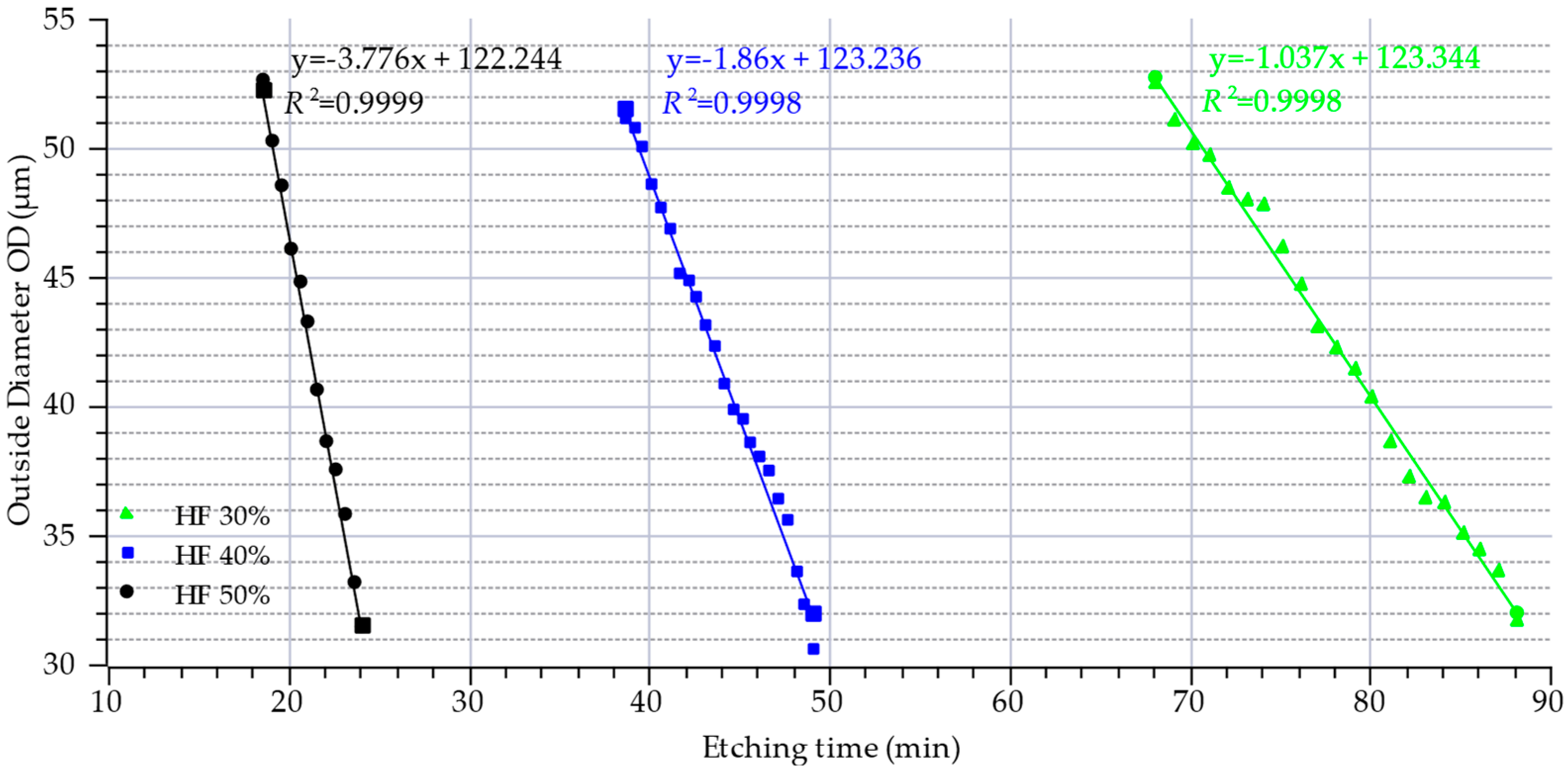
The chemically etched optical fibers prepared in this study were also utilized to determine the optimal etching parameters required to achieve the desired diameters for effective coupling with the multicore fiber. In this process, cleaned single-mode optical fibers were subjected to controlled chemical etching using hydrofluoric acid solutions of varying concentrations—specifically, 30%, 40%, and 50% by volume. The etching was conducted in stable environmental conditions in a cleanroom area at a constant ambient temperature of 20.5 °C to ensure consistency and repeatability across all test conditions. Furthermore, the use of a cleanroom area avoids the influence of ambient temperature on etching time [25] and fiber strength [26]. The duration of etching ranged from 18 to 88 min, depending on the concentration of the HFA and the targeted final diameter of the etched region. After each etching interval, the diameter of the resulting fiber diameter was measured using a Zeiss EVO MA10 scanning electron microscope (SEM). The experimental results presented in Figure 2 illustrate the etching rate behavior for each HFA concentration. As expected, higher acid concentrations resulted in faster etching rates, leading to more rapid diameter reduction. These findings are critical for defining the etching parameters required to produce low-diameter fibers with dimensions matching the inter-core spacing of the target multicore fiber.
As can be seen in Figure 2, to obtain an etched optical fiber with an assumed diameter of 37 µm, 81.5 min, 46.5 min, and 22.5 min are needed for 30%, 40%, and 50% hydrofluoric acid, respectively. Due to the long duration of the process, no noticeable differences in the fiber surface after etching, and a finally stable diameter along whole etched region, a 50% HFA solution was chosen. This concentration significantly reduces fabrication time and allows us to produce a stable diameter with a smooth surface, as can be observed in Figure 3a. After the etching process, the end face of the optical fiber has a concave profile, as can be seen in Figure 3b. It is presumed that this is concave as a result of the lower bond energy of Ge–O and the presence of defects [27]. In the present study, the end faces of the optical fibers subjected to chemical etching were subsequently cleaved and mechanically polished to achieve planar surface geometry. This post-processing step effectively eliminates any residual concave topographies induced by the etching process, thereby ensuring that such surface irregularities do not adversely affect the optical coupling efficiency.
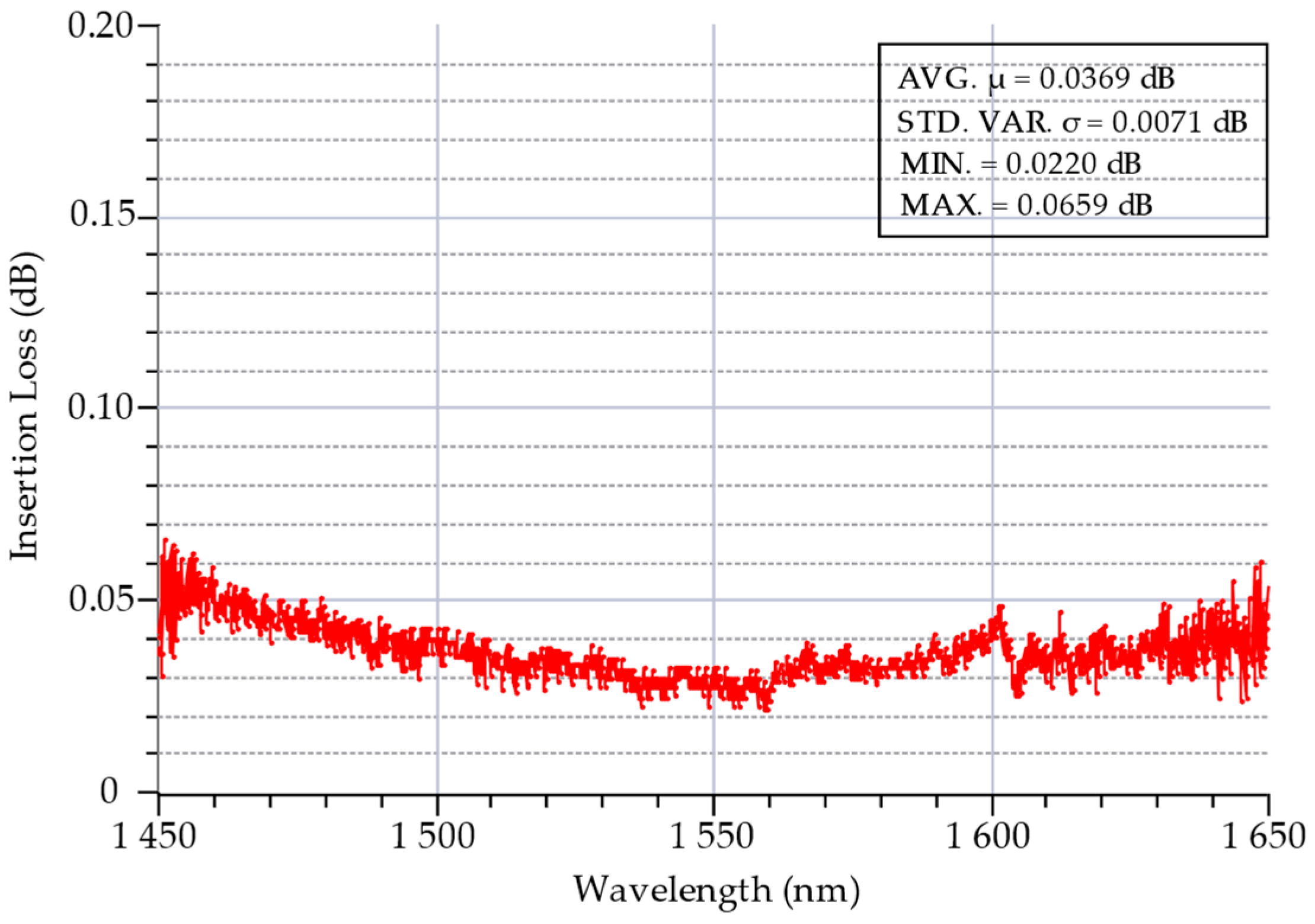
Chemically etched optical fibers exhibit a reduced cladding diameter while maintaining the original core dimensions. Since the etching process selectively removes cladding material, the fundamental propagation remains largely undisturbed. As a result, this method of tapering is expected to introduce minimal additional attenuation. To experimentally validate this assumption, we measured the transmission loss of a locally etched single-mode fiber with a final cladding diameter reduced to approximately 37 µm. The measurements were performed using a broadband laser source spanning the wavelength range from 1450 nm to 1650 nm. The results, presented in Figure 4, show that the etching process has a negligible effect on the transmission characteristics of the fiber. The observed insertion loss across the tested wavelength range did not exceed 0.06 dB, which falls within the typical range of measurement uncertainty for this type of setup. This confirms that the etching process does not degrade the optical performance of the fiber and is well-suited for use in low-loss coupling systems.
To establish optical coupling between the individual cores of a multicore fiber and etched single-core optical fibers, it is essential to arrange the etched fibers into a precisely aligned bundle. This bundle must be fabricated with high geometric accuracy to ensure that each etched fiber is laterally and angularly aligned with its corresponding core in the MCF. Misalignment at this stage can significantly degrade coupling efficiency due to mode mismatch or core offset. In this study, a SiliSeven multicore fiber with a 125 µm cladding diameter, a 10 µm mode field diameter (MFD) at 1550 nm, and an inter-core spacing of 37 µm from the no longer existing company Silitec was used. To meet these requirements, the etched fibers were fabricated so that their diameters closely matched the 37 µm inter-core spacing of the MCF. This ensures that each fiber can couple light effectively into its respective MCF core with minimal lateral displacement. In addition, the bundle of etched fibers was inserted into a standard ceramic ferrule that acts as a mechanical support structure. To accommodate the entire bundle while minimizing excess space that could lead to positional shifts, the ferrule’s internal aperture was selected to be approximately three times the diameter of an individual etched fiber. The overall mechanical and optical design strategy, including the tailored fiber etching and ferrule dimensioning, is illustrated in Figure 5, where the geometric relationship between the etched fibers, the ferrule, and the MCF core layout is depicted.
A bundle of seven chemically etched optical fibers with reduced diameters of 37 µm was placed inside a TG22-0929-1-0A custom ferrule with a 111 µm inner diameter produced by Orbray Co., Ltd. (Tokyo, Japan) [28]. TG22-0929-1-0A is dedicated to SC/PC and FC/PC connectors and includes a long 20 mm metal flange to cover fragile small-diameter fibers to protect them from damage. After fiber installation inside the ferrule, the fibers were glued with Loctite EA 0151 resin adhesive. In the next step, the FC/PC connector was assembled and polished using a Domaille HDC-3000 polishing machine produced by Domaille Engineering LLC [29]. Fiber-optic pigtails terminated with FC/PC connectors were subsequently fusion spliced to the optical fibers. The splices were enclosed within protective plastic housings. These splices are optional, as pre-terminated connectorized pigtails can alternatively be etched and employed to eliminate the need for splicing and the same reducing additional attenuation. The final FIFO device fabricated in this way was presented in Figure 6.

3. Results

3.1. Coupling Loss

The coupling loss measurement setup is presented in Figure 7. In the experiments, we used laser sources operating at wavelengths of 1310 nm and 1550 nm, which were used to characterize the performance of the fabricated FIFO device. To ensure mechanical stability and repeatable measurements, the FIFO connector was securely immobilized using a custom-designed 3D-printed blocking fixture. This fixture was specifically developed to prevent rotational shifts of the connector during the alignment procedure and realized by using a high-resolution rotating holder. This stage allowed for fine adjustments in the angular orientation of the MCF, enabling optimal matching between the FIFO output and the corresponding MCF cores. The output end of the MCF was connected directly to a photodetector for optical power measurements.
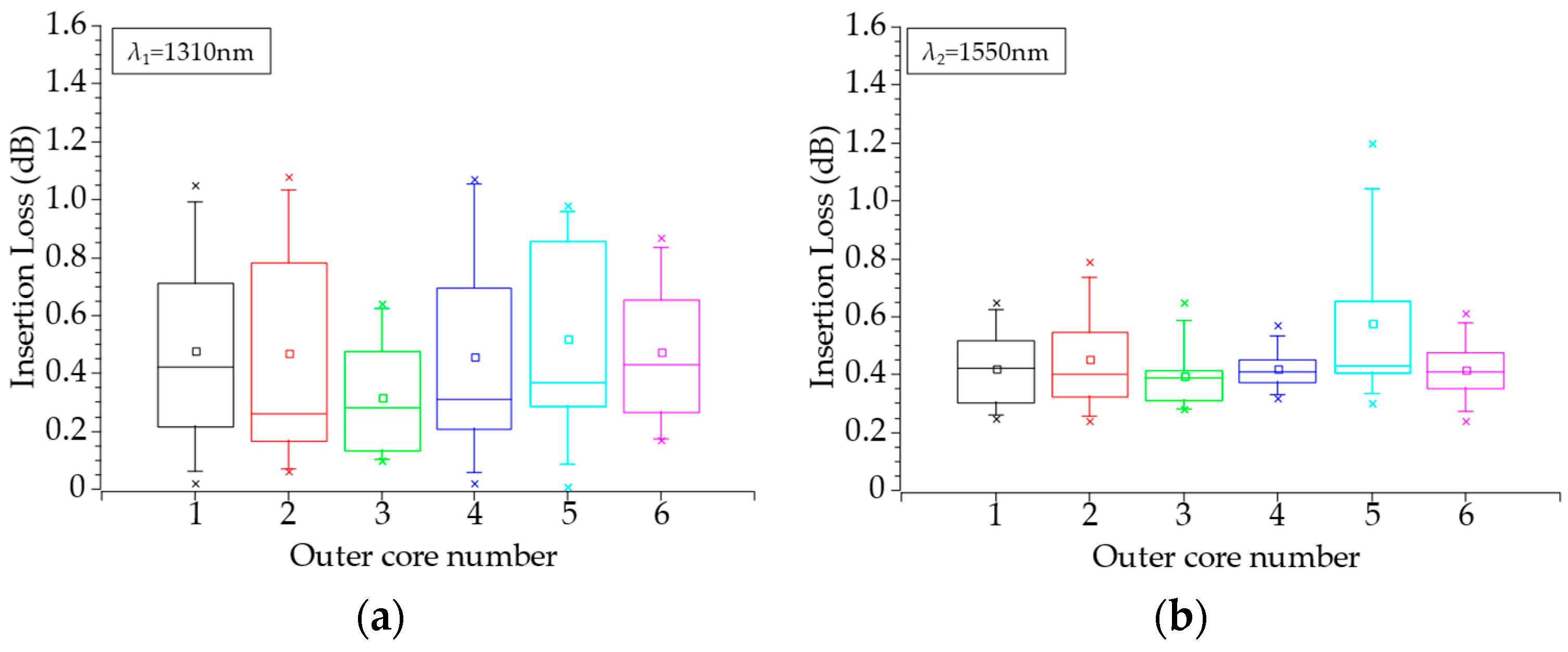
Insertion loss measurements were carried out by systematically aligning the outer cores of the FIFO device across all possible configurations. This alignment procedure ensures that the optimal coupling condition corresponding to the lowest insertion loss can be identified for each core pairing. Such a method is particularly important for etched fiber bundles, where slight misalignments or asymmetries can lead to increased optical loss due to mode mismatch or core offset. Attenuation was evaluated at two standard telecommunications wavelengths: 1310 nm and 1550 nm. The resulting insertion loss values for each core and alignment configuration are presented in Table 1 and Table 2, while a graphical summary is provided in Figure 8. The measurements confirm that the device consistently achieves low insertion loss, with the best-case configuration values of 0.32 dB and 0.40 dB at 1310 nm and 1550 nm, respectively. These results validate the high coupling efficiency of the chemically etched fibers and demonstrate the effectiveness of the alignment process. Moreover, the reproducibility of low-loss configurations across different channels highlights the mechanical stability and uniformity of the fabricated structure. Future improvements may focus on automated alignment or custom ferrule designs to further streamline this process for scalable production.
For the best configuration, we achieved average insertion losses equal to 0.32 dB and 0.40 dB for 1310 nm and 1550 nm wavelengths, respectively. Low coupling loss is a result of the lack of additional attenuation of chemically etched optical fibers. The observed insertion losses can be attributed to multiple contributing factors. The first category arises from manufacturing tolerances, including core eccentricity in SMFs, deviations in core-to-core spacing within the multicore fiber (MCF), and dimensional inaccuracies of the ferrule inner diameter. A second category of sources of insertion losses is associated with the fabrication process itself, such as non-uniform fiber diameters resulting from etching and deviations from an ideal hexagonal (honeycomb) lattice in the spatial distribution of the fibers and due to non-ideal alignment between the bundle of EOFs and the MCF. All these defects show that this method can be improved in the future, and hence coupling loss can be decreased.

3.2. Crosstalk

The crosstalk of the fabricated FIFO device was measured at a wavelength of 1550 nm using the Fresnel Reflection-Based Method, which exploits the Fresnel reflection phenomenon occurring at the glass–air interface to evaluate the level of inter-core signal leakage in FIFO structures [30]. This technique is particularly suitable for passive optical components, as it enables non-intrusive, high-sensitivity measurement of back reflected signals originating from adjacent channels. In this method, an optical input is launched into a single core, and the reflected power from surrounding cores is analyzed to determine the crosstalk level. Experimental results, summarized in Table 3, indicate that the crosstalk remains below −41.8 dB across all measured channels, with an average value of −49.2 dB. These values are consistent with those typically reported for similar tapered fiber bundle-based FIFO configurations, confirming the effectiveness of the fiber etching and alignment technique employed in our fabrication process. The relatively low standard deviation in crosstalk measurements also suggests good uniformity and channel isolation across the device. The measured performance validates the optical and mechanical integrity of the fabricated device and supports its applicability in next-generation fiber-optic communication systems requiring low interference between cores.

3.3. Return Loss

To verify the polishing process of the FIFO optical fiber end faces and the presence of the air gap in the connection, return loss measurements were performed. The JDSU RM3 back reflection meter and the mandrel wrapping technique for the termination points were used. The results are shown in Table 4. The reflectance of the polishing bundle was equal to −14.5 dB ± 0.2 dB (glass–air interface) for both 1310 nm and 1550 nm wavelengths, which is typical for cleaved-type optical fibers. The return loss increases to average levels of −53 dB ± 1.5 dB and −53.9 dB ± 1.6 dB, respectively, for both wavelengths.

4. Discussion

The fabrication of a fan-in/fan-out (FIFO) device based on chemically etched optical fibers embedded in an FC/PC connector demonstrated promising results for multicore fiber (MCF) coupling applications. The detailed fabrication process allowed for controlled etching and alignment of individual fiber cores, resulting in a compact and connectorized solution suitable for practical deployment. The measured coupling losses of 0.32 dB at 1310 nm and 0.40 dB at 1550 nm confirm the effectiveness of the etching and alignment method. These values are within the expected range for such devices and indicate low insertion loss, which is critical for maintaining signal integrity in high-bandwidth communication systems. In addition to low insertion loss, the system exhibited excellent isolation characteristics. The crosstalk level, which was measured to be below −41.8 dB, suggests minimal core-to-core interference, which is essential for parallel signal transmission in multicore architectures. Similarly, a back reflection of below −51.3 dB is well within acceptable limits, ensuring compatibility with reflection-sensitive components such as lasers and photodetectors. However, some minor fabrication imperfections were identified. Specifically, one channel was found to be slightly misaligned from the optimal position, leading to an increase in coupling loss. This highlights the sensitivity of the FIFO system to precise core alignment, emphasizing the need for improved mechanical accuracy during the assembly and fixation of the etched fibers within the connector housing. Overall, the performance metrics achieved—low coupling loss, minimal crosstalk, and low back reflection—demonstrate the high potential of this FIFO structure for scalable MCF interfacing. Future improvements should focus on enhancing alignment repeatability, possibly through the integration of automated positioning systems or custom ferrules tailored for multicore geometries. Addressing these refinements will be crucial for transitioning the demonstrated concept into robust, high-yield production suitable for real-world optical networks.

Author Contributions

Conceptualization, A.W.; Methodology, Z.L.; Formal analysis, M.Ł.; Investigation, A.W.; Data curation, M.Ł.; Writing–original draft, A.W.; Writing–review & editing, M.Ł.; Visualization, A.W. and M.Ł.; Supervision, Z.L. All authors have read and agreed to the published version of the manuscript.

Funding

This research received no external funding.

Data Availability Statement

The original contributions presented in this study are included in the article. Further inquiries can be directed to the corresponding author.

Acknowledgments

This article was completed while the first author was a Doctoral Candidate in the Interdisciplinary Doctoral School at the Lodz University of Technology, Poland.

Conflicts of Interest

The authors declare no conflict of interest.

Abbreviations

The following abbreviations are used in this manuscript:
FIFOFan-in/Fan-out device
SMFSingle-mode optical fiber
MCFMulticore fiber
HFAHydrofluoric acid
EOFEtched optical fiber
TOFTapered optical fiber
MFDMode field diameter
SEMScanning electron microscopy
AVGAverage
STD DEVStandard deviation

References

  1. Gan, L.; Zhou, J.; Shen, L.; Guo, X.; Wang, Y.; Yang, C.; Tong, W.; Xia, L.; Fu, S.; Tang, M.; et al. Ultra-Low Crosstalk Fused Taper Type Fan-In/Fan-Out Devices for Multicore Fibers. In Proceedings of the 2019 Optical Fiber Communications Conference and Exhibition (OFC), San Diego, CA, USA, 3–7 March 2019; pp. 1–3. [Google Scholar]
  2. Watanabe, K.; Saito, T. Compact fan-out for 19-core multicore fiber, with high manufacturability and good optical properties. In Proceedings of the 2015 Opto-Electronics and Communications Conference (OECC), Shanghai, China, 28 June–2 July 2015. [Google Scholar]
  3. Kopp, V.I.; Park, J.; Singer, J.; Neugroschl, D.; Gillooly, A. Low Return Loss Multicore Fiber-Fanout Assembly for SDM and Sensing Applications. In Proceedings of the Optical Fiber Communication Conference (OFC) 2020, San Diego, CA, USA, 8–12 March 2020. [Google Scholar]
  4. Cui, J.; Zhu, S.; Feng, K.; Hong, D.; Li, J.; Tan, J. Fan-out device for multicore fiber coupling application based on capillary bridge self-assembly fabrication method. Opt. Fiber Technol. 2015, 26, 234–242. [Google Scholar] [CrossRef]
  5. Watanabe, K.; Saito, T.; Imamura, K.; Shiino, M. Development of fiber bundle type fan-out for multicore fiber. In Proceedings of the 2012 17th Opto-Electronics and Communications Conference, Busan, Republic of Korea, 2–6 July 2012; pp. 475–476. [Google Scholar]
  6. Uemura, H.; Takenaga, K.; Ori, T.; Matsuo, S.; Saitoh, K.; Koshiba, M. Fused taper type fan-in/fan-out device for multicore EDF. In Proceedings of the 2013 18th OptoElectronics and Communications Conference Held Jointly with 2013 International Conference on Photonics in Switching (OECC/PS), Kyoto, Japan, 30 June–4 July 2013; pp. 1–2. [Google Scholar]
  7. Abe, Y.; Shikama, K.; Yanagi, S.; Takahashi, T. Low-loss physical-contact-type fan-out device for 12-core multicore fiber. In Proceedings of the 39th European Conference and Exhibition on Optical Communication (ECOC 2013), London, UK, 22–26 September 2013; IET Conference Publications: Stevenage, UK, 2013; pp. 861–863. [Google Scholar]
  8. Qiao, G.; Yang, Y.; Ji, H.; Huang, S.; Long, C.; Gao, Y.; Zuo, M.; Zhang, J.; Xu, Z.; Wu, Q.; et al. 205.8Tb/s Weakly-Coupled 2-Mode 7-Core Transmission Over 1170-km FM-MCF Only Using 2×2 MIMO-DSP. In Proceedings of the 2024 Optical Fiber Communications Conference and Exhibition (OFC), San Diego, CA, USA, 24–28 March 2024; pp. 1–3. [Google Scholar]
  9. Tottori, Y.; Kobayashi, T.; Watanabe, M. Low loss optical connection module for seven-core multicore fiber and seven single-mode fibers. IEEE Photonics Technol. Lett. 2012, 24, 1926–1928. [Google Scholar] [CrossRef]
  10. Klaus, W.; Sakaguchi, J.; Puttnam, B.J.; Awaji, Y.; Wada, N.; Kobayashi, T.; Watanabe, M. Free-Space Coupling Optics for Multicore Fibers. IEEE Photonics Technol. Lett. 2012, 24, 1902–1905. [Google Scholar] [CrossRef]
  11. Lee, Y.; Tanaka, K.; Hiruma, K.; Nomoto, E.; Sugawara, T.; Arimoto, H. Experimental Demonstration of a Highly Reliable Multicore-Fiber-Based Optical Network. IEEE Photonics Technol. Lett. 2014, 26, 538–540. [Google Scholar] [CrossRef]
  12. Shimakawa, O.; Arao, H.; Harumoto, M.; Sano, T.; Inoue, A. Compact multi-core fiber fan-out with GRIN-lens and micro-lens array. In Proceedings of the OFC 2014, San Francisco, CA, USA, 9–13 March 2014. [Google Scholar]
  13. Oh, J.; Yang, J.; Marra, L.; Dorrah, A.H.; Palmieri, A.; Dainese, P.; Capasso, F. Metasurfaces for Free-Space Coupling to Multicore Fibers. J. Light. Technol. 2024, 42, 2385–2396. [Google Scholar] [CrossRef]
  14. Suganuma, D.; Ishigure, T. Fan-in/out polymer optical waveguide for a multicore fiber fabricated using the Mosquito method. Opt. Express 2015, 23, 1585–1593. [Google Scholar] [CrossRef] [PubMed]
  15. Thomson, R.R.; Bookey, H.T.; Psaila, N.D.; Fender, A.; Campbell, S.; Macpherson, W.N.; Barton, J.S.; Reid, D.T.; Kar, A.K.; Gander, M.J.; et al. Ultrafast-laser inscription of a three dimensional fan-out device for multicore fiber coupling applications. Opt. Express 2007, 15, 11691–11697. [Google Scholar] [CrossRef] [PubMed]
  16. Watanabe, T.; Hikita, M.; Kokubun, Y. Laminated polymer waveguide fan-out device for uncoupled multicore fibers. Opt. Express 2012, 20, 26317. [Google Scholar] [CrossRef] [PubMed]
  17. Ams, M.; Marshall, G.D.; Withford, M.J. Study of the influence of femtosecond laser polarisation on direct writing of waveguides. Opt. Express 2006, 14, 13158–13163. [Google Scholar] [CrossRef] [PubMed]
  18. Shikama, K.; Abe, Y.; Ono, H.; Aratake, A. Low-Loss and Low-Mode-Dependent-Loss Fan-In/Fan-Out Device for 6-Mode 19-Core Fiber. J. Light. Technol. 2018, 36, 302–308. [Google Scholar] [CrossRef]
  19. Zhu, B.; Taunay, T.F.; Yan, M.F.; Fini, J.M.; Fishteyn, M.; Monberg, E.M.; Dimarcello, F.V. Seven-core multi-core fiber transmissions for passive optical network. Opt. Express 2010, 18, 11117. [Google Scholar] [CrossRef] [PubMed]
  20. Matsui, T.; Pondillo, P.L.; Nakajima, K. Weakly Coupled Multicore Fiber Technology, Deployment, and Systems. Proc. IEEE 2022, 110, 1772–1785. [Google Scholar] [CrossRef]
  21. Anderson, G.P.; Golden, J.P.; Ligler, F.S. A fiber optic biosensor: Combination tapered fibers designed for improved signal acquisition. Biosens. Bioelectron. 1993, 8, 249–256. [Google Scholar] [CrossRef]
  22. Zhong, N.; Liao, Q.; Zhu, X.; Wang, Y.; Chen, R. High-quality fiber fabrication in buffered hydrofluoric acid solution with ultrasonic agitation. Appl. Opt. 2013, 52, 1432–1440. [Google Scholar] [CrossRef] [PubMed]
  23. Spierings, G.A.C.M. Wet chemical etching of silicate glasses in hydrofluoric acid based solutions. J. Mater. Sci. 1993, 28, 6261–6273. [Google Scholar] [CrossRef]
  24. Zhang, E.J.; Sacher, W.D.; Poon, J.K.S. Hydrofluoric acid flow etching of low-loss subwavelength-diameter biconical fiber tapers. Opt. Express 2010, 18, 22593–22598. [Google Scholar] [CrossRef] [PubMed]
  25. Xiao, H.; Wang, H.; Fu, G.; Chen, Z. Surface roughness and morphology evolution of optical glass with microcracks during chemical etching. Appl. Opt. 2017, 56, 702–711. [Google Scholar] [CrossRef] [PubMed]
  26. Kurkjian, C.R.; Matthewson, M.J.; Rooney, J.M. Effects of heat treatment and HF etching on the strength of silica lightguides. In Reliability of Optical Fiber Components, Devices, Systems, and Networks II; Limberger, H.G., Matthewson, M.J., Eds.; SPIE: Pune, India, 2004; Volume 5465, pp. 223–229. [Google Scholar]
  27. Machavaram, V.R.; Badcock, R.A.; Fernando, G.F. Fabrication of intrinsic fibre Fabry–Perot sensors in silica fibres using hydrofluoric acid etching. Sens. Actuators A Phys. 2007, 138, 248–260. [Google Scholar] [CrossRef]
  28. Orbray Co., Ltd. Available online: https://orbray.com/en/ (accessed on 1 August 2025).
  29. Domaille Engineering. Available online: https://www.domailleengineering.com/ (accessed on 1 August 2025).
  30. Ye, F.; Ono, H.; Abe, Y.; Yamada, M.; Morioka, T. Novel Crosstalk Measurement Method for Multi-Core Fiber Fan-In/Fan-Out Devices. IEEE Photonics Technol. Lett. 2016, 28, 2269–2272. [Google Scholar] [CrossRef]
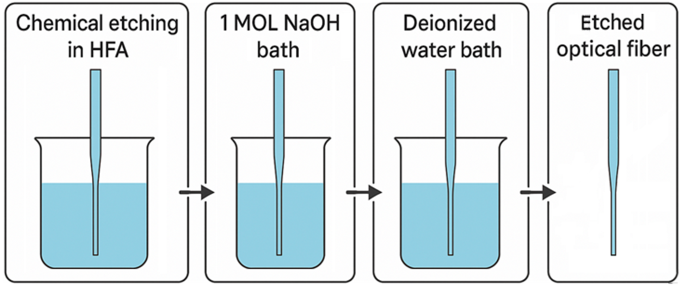
Figure 1. Etched optical fiber fabrication process.
Electronics 14 03479 g001
Figure 2. Characteristics of optical fiber diameter changes as a function of etching time in hydrofluoric acid at concentrations of 30%, 40%, and 50%, T = 20.5 °C.
Electronics 14 03479 g002
Figure 3. Optical fiber surface (a) and front end (b) after etching in 50% HFA solution.
Electronics 14 03479 g003
Figure 4. Dependence of wavelength on the insertion loss of the etched optical fiber section.
Electronics 14 03479 g004
Figure 5. Comparison of a fiber-optic connector terminated with (a) a multi-core optical fiber and (b) a bundle of chemically etched optical fibers.
Electronics 14 03479 g005
Figure 6. (a) Fabricated multicore fiber FIFO device for 37 µm core-to-core spacing multicore optical fiber. (b) Forehead of the FIFO device.
Electronics 14 03479 g006
Figure 7. Insertion loss measurement setup.
Electronics 14 03479 g007
Figure 8. Insertion loss distribution of the fabricated FIFO device for wavelengths of (a) 1310 nm and (b) 1550 nm.
Electronics 14 03479 g008
Table 1. Coupling loss of fabricated FIFO device for a 1310 nm wavelength.
Coupling Loss λ = 1310 nm [dB]
FIFO Aligned to Outer CoreAVGSTD DEVMAXMIN
10.480.371.050.02
20.470.411.080.06
30.320.220.640.10
40.460.421.070.02
50.520.370.980.01
60.470.270.870.17
Table 2. Coupling loss of fabricated FIFO device for a 1550 nm wavelength.
Coupling Loss λ = 1550 nm [dB]
FIFO Aligned to Outer CoreAVGSTD DEVMAXMIN
10.420.150.650.25
20.450.190.790.24
30.400.130.650.28
40.420.080.570.32
50.580.301.200.30
60.420.120.610.24
Table 3. The crosstalk of the fabricated FIFO device.
Crosstalk [dB]
Core 0Core 1Core 2Core 3Core 4Core 5Core 6
Core 0-−48.5−46.3−45.8−43.2−43.4−42.6
Core 1−46.5-−49.5−54.2−56.7−55.4−51.4
Core 2−53.7−44.7-−48.7−51.4−58.2−54.8
Core 3−51.5−49.3−47.2-−44.4−52.6−55.1
Core 4−41.8−53.4−49.7−44.3-−47.1−48.6
Core 5−47.1−50.2−48.5−48.1−47.9-−45.8
Core 6−45.8−48.7−52.4−51.7−50.7−47.5-
Table 4. The return loss results of the fabricated FIFO device.
Return Loss [dB]
1310 nm1550 nm
Core 0−55.5−56.5
Core 1−52.1−53.4
Core 2−51.9−52.4
Core 3−51.3−52.7
Core 4−54.4−55.8
Core 5−52.4−52.9
Core 6−53.1−53.4
Disclaimer/Publisher’s Note: The statements, opinions and data contained in all publications are solely those of the individual author(s) and contributor(s) and not of MDPI and/or the editor(s). MDPI and/or the editor(s) disclaim responsibility for any injury to people or property resulting from any ideas, methods, instructions or products referred to in the content.