1. Introduction
Electrical energy storage is the key solution to optimise the exploitation of renewable energy resources, as enshrined in the objectives of the European governments’ strategic initiatives aiming at the green transition and climate neutrality in the next years [
1]. In particular, as the energy sector transitions from centralised fossil-fuel-based production to decentralised renewable generation, the ability to buffer electrical energy becomes essential for ensuring grid stability, load balancing, and energy availability in both residential and commercial sectors. At the same time, the increasing electrification and digitalisation of modern buildings have introduced new challenges related to electromagnetic compatibility (EMC). Contemporary structures are densely populated with electrical and electronic systems, making them increasingly exposed to both intentional and unintentional electromagnetic fields (EMFs). Energy-efficient buildings are especially characterised by the widespread deployment of sensors, controllers, and communication modules, which are orchestrated through software platforms forming the backbone of Internet of Things (IoT) infrastructures. These IoT systems constitute the operational intelligence of so-called
smart cities, that are digitally advanced urban environments designed to optimise resource use and reduce environmental impact [
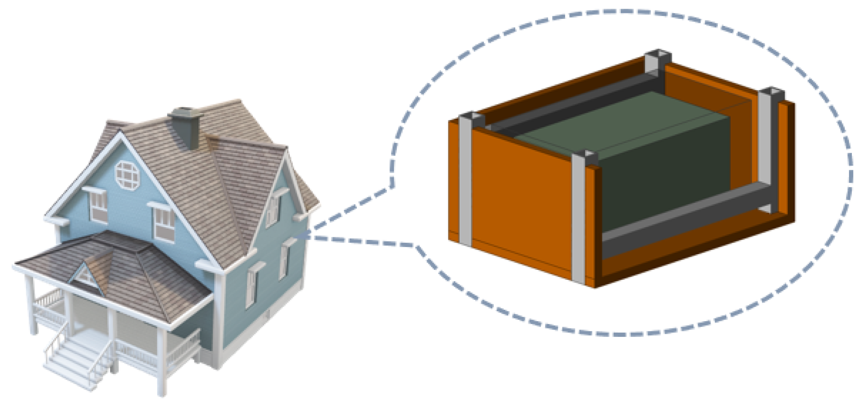
2]. In this evolving technological context, the concept of energy-buffering structural layers (modular units that simultaneously fulfil structural, thermal, and electrical functions) emerges as a promising solution. These multifunctional components, as investigated in the present work and illustrated in
Figure 1, offer a compelling solution to the integration of electrical energy storage directly within the building envelope [
3]. By embedding energy storage elements within walls or other architectural elements, it becomes possible to reduce transmission losses, facilitate demand-side management, and support decentralised energy systems.
However, the introduction of energy-buffering structural layers also necessitates a careful analysis of their interaction with electromagnetic fields, particularly in the frequency ranges employed by mobile telephony, radio broadcasting, and wireless data transmission. Since these electromagnetic fields permeate living spaces and are critical for the functioning of IoT networks, it is crucial to assess whether integrated energy storage systems may interfere with or, conversely, mitigate electromagnetic propagation. The interaction with low-frequency fields, such as those at 50–60 Hz typically associated with power lines, is considered negligible in this context. This is due to the extremely large wavelength of such fields (on the order of several thousand kilometres), which allows them to penetrate thin conductive materials such as the metallic layers used in capacitors or the mounting brackets found in building assemblies.
Moreover, intentional electromagnetic interference (IEMI) poses a significant and emerging threat to energy-efficient storage buildings and other critical infrastructures in modern urban areas. Intentional attacks by criminals or malicious actors, which can target power electronics through conducted and radiated susceptibility mechanisms, are gaining increased attention in both civilian and military sectors. IEMI attacks fall into two main categories: radiated interference, which involves electromagnetic fields radiating and affecting wireless devices, and conducted interference, which involves injecting malicious signals into power or signal lines. The propagation paths of the two attack modes are different, and they call for different defence and assessment strategies. Conducted immunity testing assesses how power electronic devices withstand interference conducted along physical connections such as power leads or communication cables. These tests often involve injecting specific transient signals through coupling transformers or probes to simulate switching transients, bursts, surges, and spikes that may be introduced intentionally or naturally. To assess device immunity levels, a series of conducted susceptibility tests (e.g., CS115 for fast transients, CS116 for damped sinusoidal transients) are defined by common test standards like MIL-STD-461G [
4]. Testing setups typically involve calibrated injection devices, and the evaluation includes verifying that the device maintains proper operation under these conditions. Relevant standards also include IEC 61000-4-6 [
5], which describes immunity testing under conducted disturbance conditions in the frequency range relevant to power and signal lines. These tests help manufacturers identify vulnerabilities in device designs and improve resilience against malicious attacks conducted on critical power electronics equipment. Radiated immunity testing evaluates the ability of electronic devices to operate without significant degradation when exposed to externally generated electromagnetic fields. It is performed in controlled environments such as anechoic chambers where devices under test (DUTs) are exposed to frequency sweeps (commonly 80 MHz to 1000 MHz per IEC 61000-4-3 [
6]). The objective is to identify the threshold at which malfunction is caused by radiated fields. Concerns about radiation immunity are particularly important because adversaries can deteriorate or interfere with device functionality by using continuous wave signals or high-power electromagnetic pulses. Recent research also includes advanced methods for evaluating worst-case radiated interference on linear multiport systems like wiring harnesses, optimising assessment of the voltage peaks induced on devices by intentionally radiated electromagnetic fields [
7]. This research provides a theoretical and practical framework for modelling and mitigating radiated electromagnetic threats to power electronics in critical infrastructures.
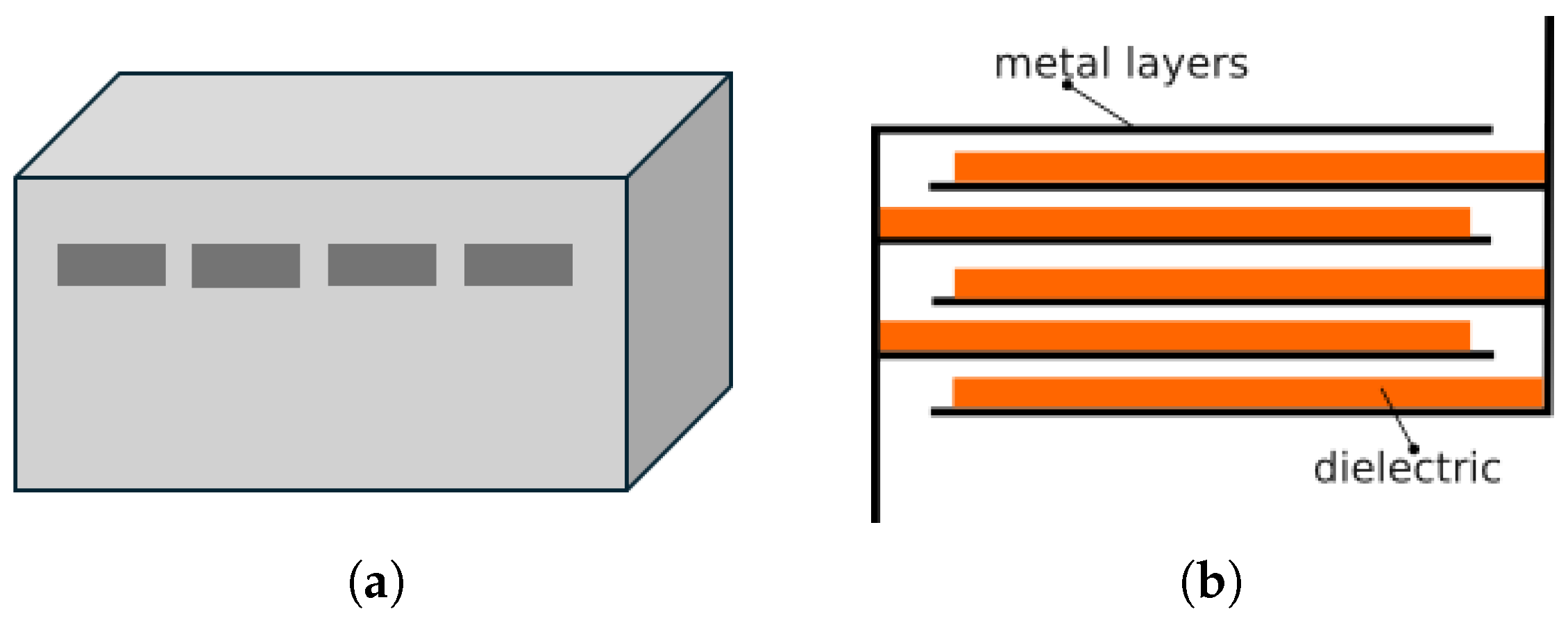
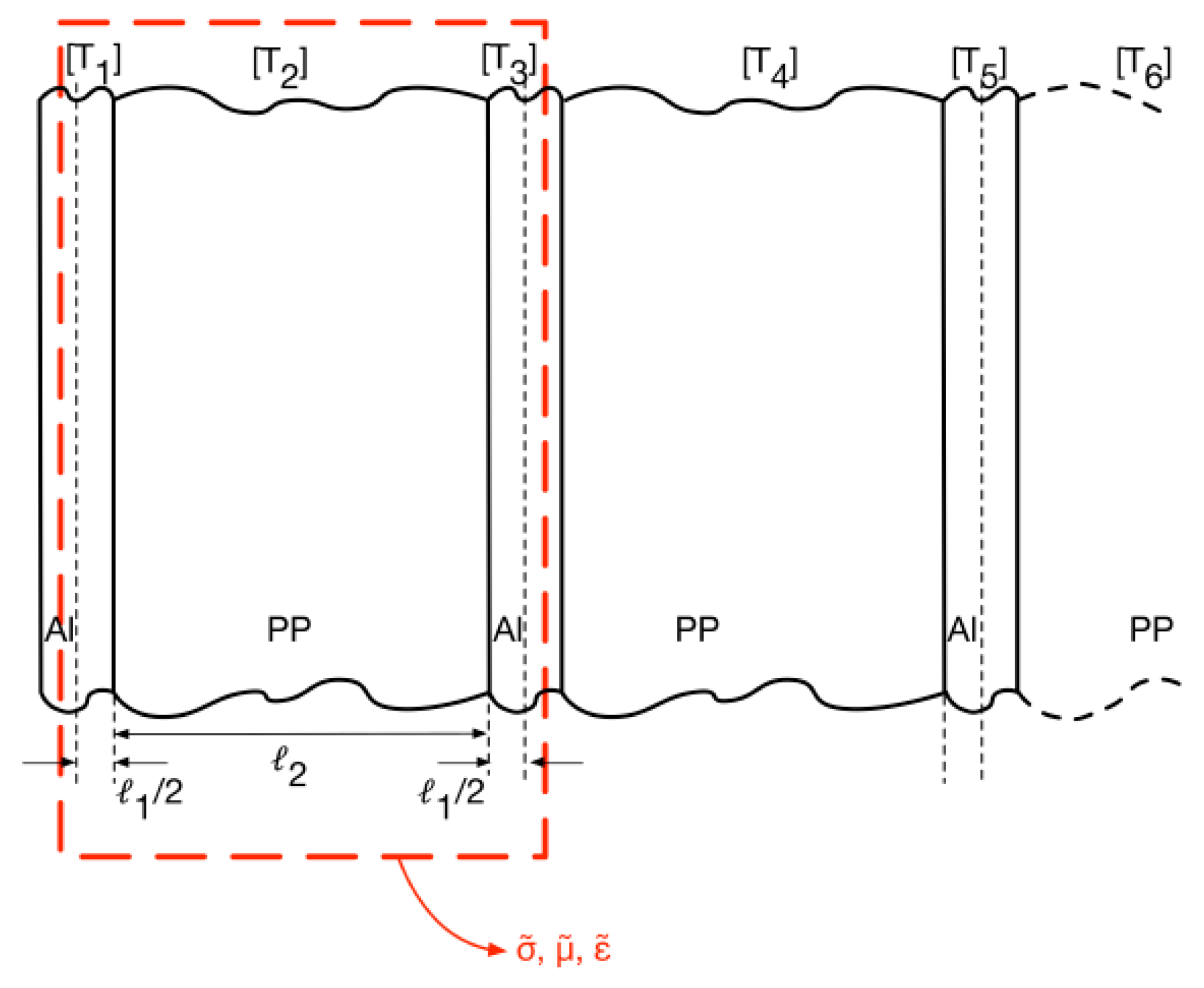
The electrical energy storage system analysed in this study is based on a multilayer capacitor comprising multiple stacks of metallised dielectric sheets, arranged in compact configurations. These capacitive modules are embedded within structural elements, forming the core of the energy-buffering layers. The sheets are oriented parallel to the surface of the capacitor enclosure, a configuration that not only supports efficient energy storage but also enhances thermal insulation and reduces the transmission of acoustic vibrations in the direction normal to the wall surface. This dual functionality positions the capacitor as a multifunctional element capable of storing electrical energy while also contributing to thermal and acoustic regulation. The primary objective of this paper is to explore a third potential function: the ability of these embedded capacitors to provide electromagnetic shielding. Given their multilayered structure and the presence of conductive surfaces, these devices may attenuate or reflect incident electromagnetic waves, offering a passive EMC benefit in environments increasingly dominated by wireless communication technologies.
The work presented herein focuses on the characterisation of the capacitor’s electromagnetic behaviour and its implications for integration in smart building environments. The broader aim is to evaluate the feasibility of using such multifunctional components to support not only the energy needs but also the electromagnetic compatibility of future sustainable buildings.
4. Implementation and Results
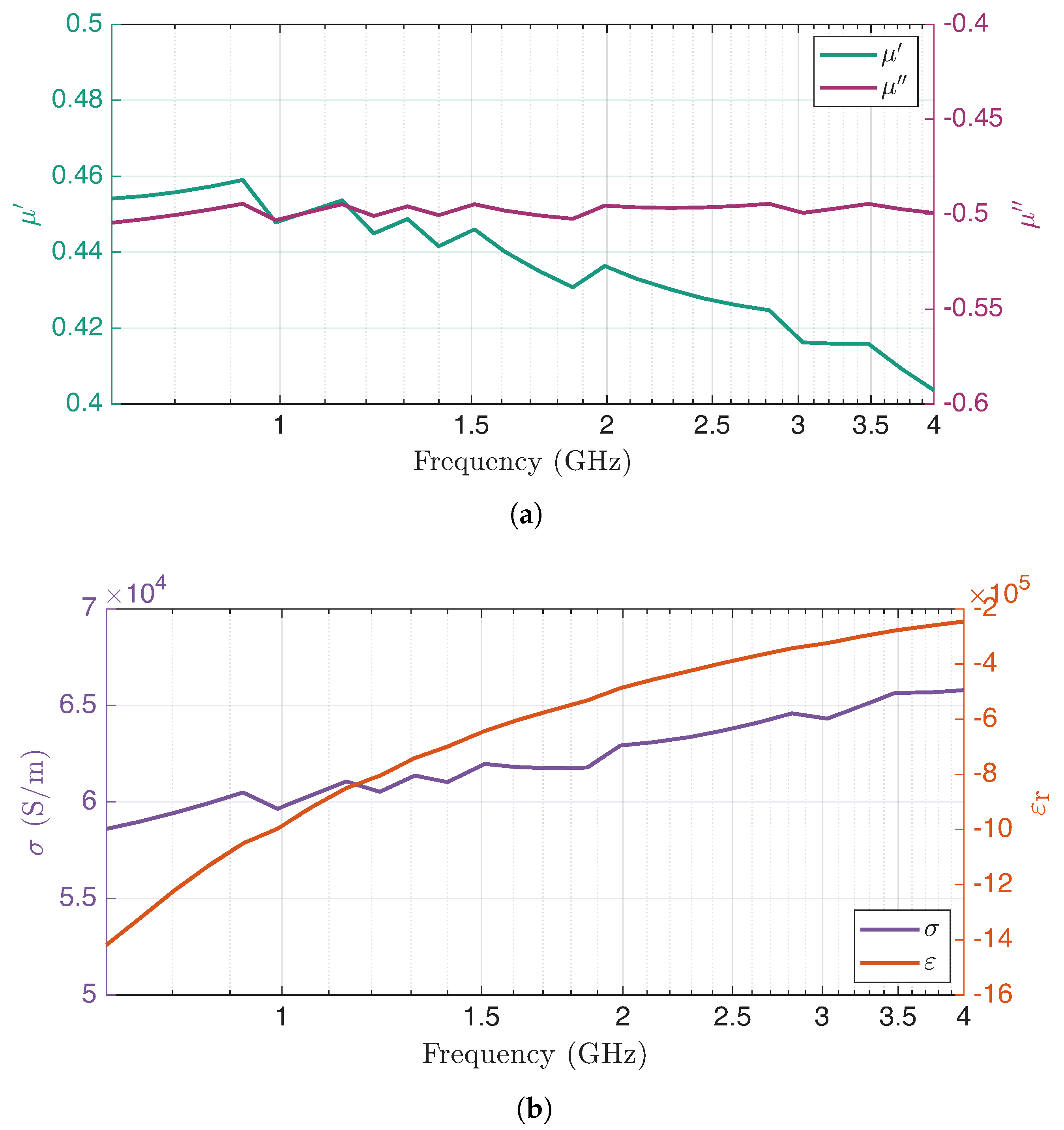
The effective parameters of the homogenised capacitor obtained as a function of frequency are shown in
Figure 4. The energy-buffering structural layer containing the capacitor, namely the brick, is then formed by a wooden structure (brown part in
Figure 1) supported by square cross-section steel tubes (grey in
Figure 1), which also serve as electrical connectors. The capacitor is housed inside the brick together with elements for acoustic and thermal shielding, which, however, do not influence the electromagnetic field at the frequencies of interest.
4.1. Numerical Simulations
To numerically evaluate the shielding effectiveness of the homogenised capacitor, it is necessary to illuminate it with a plane wave and evaluate the attenuation of this wave downstream of the shield. FEM simulations with Ansys Maxwell© were carried out. In analogy with the experimental tests, described in the next section, the SE is evaluated through the power transferred between the regions upstream and downstream of the homogenised capacitor calculating the S parameters relevant to a two-port network representing the homogenised capacitor. The S matrix (scattering matrix) is defined as follows:
where the terms
and
represent the power waves incident on ports 1 and 2 of the two-port network, respectively, and
and
represent the power waves reflected back from ports 1 and 2, respectively.
The shielding effectiveness therefore corresponds to the difference between the parameter , which represents the transmission coefficient, calculated without and with the shield (i.e., the homogenised capacitor). Being interested in the interaction of the object with the wave in its propagation direction only, a parallelepiped domain of 26.9 cm × 15.5 cm (rectangular cross-section) × 160 cm (length of the simulation waveguide) has been used. The boundary conditions were chosen in such a way to impose the propagation of the plane wave in the waveguide along the positive x-direction, i.e., by imposing the following:
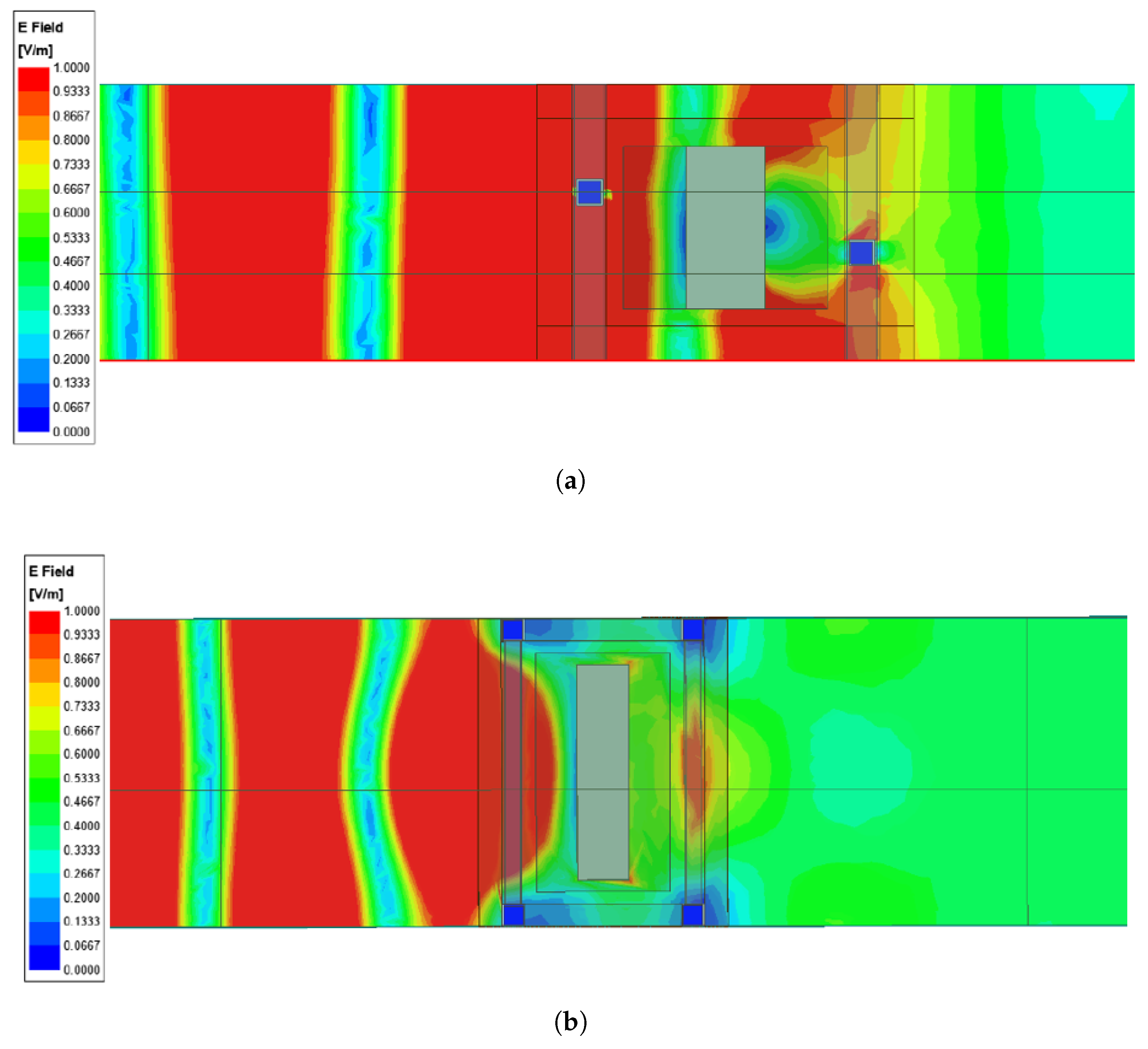
The simulated electric field is plotted in
Figure 5a,b for planes cutting the brick in half, considering the side and the top views, respectively. Its value is normalised with respect to the input one (the one obtained without the shield) and clearly shows the presence of standing waves. The vertical plane (
Figure 5a, i.e., the side view) indicates that the homogenised capacitor contributes the most to the shielding because the electric field is very low at the interface. From the horizontal plane (
Figure 5b, i.e., the top view), it can be seen that also the metallic parts of the supporting structure play a role in the shielding, since they alter the electric field distribution.
4.2. Experimental Setup
Measurements of the shielding effectiveness on a single energy-buffering system prototype were carried out with reference to the IEEE Std 299:2006 standard [
15]. The selected frequency range was 800 MHz–3.6 GHz, a range covering part of frequency bands commonly employed by 2G–3G–4G–5G cellular telephony. The range was limited by the available instrumentation. The method illustrated in [
15] makes use of two twin antennas, one transmitting (TX) and another receiving (RX), connected to the output and input ports of a Vector Network Analyser (VNA), respectively. The measurement of the SE consists in calculating the ratio between the electromagnetic field received by the RX antenna with and without the shield between the antennas.
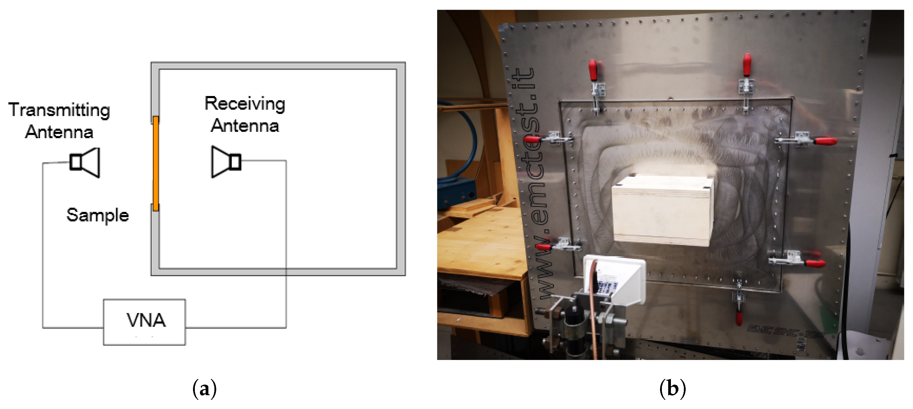
A schematic diagram illustrating the measurement setup for the SE is shown in
Figure 6a. The shield can thus be characterised in terms of the “insertion loss” caused by the shield interposed between the TX and RX antennas. The laboratory measurement setup is shown in
Figure 6b, where a screened enclosure of dimensions 1 m × 1 m × 1.1 m with an aperture and the brick sample prototype positioned on the aperture is used. The transmitting horn antenna is visible, too. Horn antennas are preferred due to their enhanced directivity.
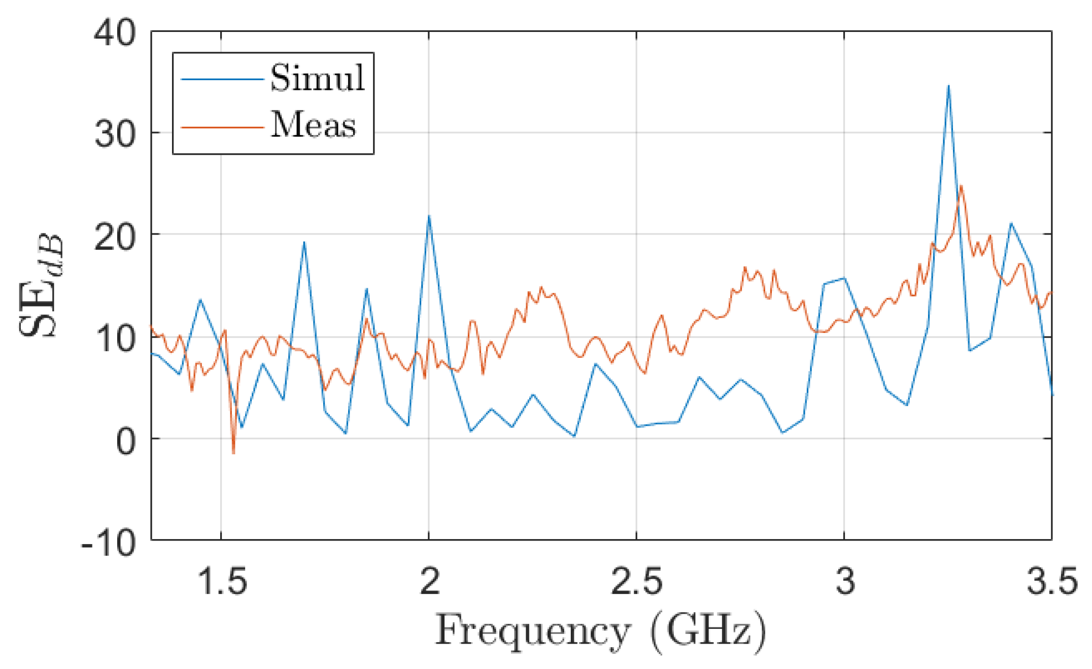
The comparison of the simulated and measured SE is shown in
Figure 7. Although the simulations indicate higher values for many frequencies of the frequency range, the trend of the SE as the frequency increases is similar. It has to be noticed that comparison is purely indicative, as the simulation results are obtained exploiting a plane wave in a waveguide, whereas in the measurement twin antennas were used, generating a field configuration which approximates that of a plane wave depending on the frequency and distance. Thus, differences between simulated and measured values can be reasonably expected. In any case, being the predicted SE lower than the measured one, it can be concluded that the simulation provides a conservative estimation of the capability of the energy-buffering system to provide attenuation to electromagnetic fields. In any case, the measured/simulated SE of the energy-buffering system is below 20 dB over the whole frequency range, and thus the shielding provided by the energy-buffering system is very limited.
