Abstract
Medium-voltage energy storage converter equipment is an important component of the new generation of ship power and power systems. Virtual space vector pulse width modulation, as a modulation optimization method to improve the neutral-point voltage imbalance in medium- and high-voltage multilevel energy storage converters, has become a research hotspot for T-type three-level energy storage inverter modulation methods due to its significant balancing effect and simple implementation. However, the current research method of constructing virtual vectors through redundant small vectors has limitations in regulating the neutral-point potential under full (especially high) modulation ratios. This paper proposes a modulation method that uses hybrid variable virtual small vectors and virtual medium vectors through optimization selection and reconstruction of basic vectors. This method ensures that the neutral-point charge change of the vector is zero and the common-mode voltage is minimized within the switching period under the full modulation ratio, achieving the purpose of controlling the neutral-point voltage balance and suppressing the common-mode voltage. Finally, simulation and experimental results show that the proposed method has good neutral-point voltage regulation and common-mode voltage suppression capabilities within the full modulation ratio range, and the system also has strong robustness and adaptability under different load conditions.
1. Introduction
The Integrated Power System (IPS) is a breakthrough technology used in modern naval ships, utilizing electrical energy as a unified medium for power generation, distribution, conversion, consumption, and storage across entire vessels. In recent years, the introduction of medium-voltage direct current (MVDC) systems and energy storage components has led to the widespread adoption of medium-voltage energy storage multilevel converters in next-generation naval power systems. Generally, medium voltage ranges from 1 kV to 50 kV, which not only meets the needs of large-capacity power transmission for ships but also strikes a balance between equipment costs and safety. Among these solutions, the three-level energy storage inverter has gained attention for its advantages, including low switching frequency, reduced switching losses, and minimal output harmonics.
It is worth noting that the T-type three-level inverter is an improved topological structure derived from the neutral-point-clamped (NPC) three-level inverter. The core reasons why it is suitable for medium-voltage systems are as follows: On one hand, compared with two-level inverters, it can reduce the voltage change rate through multilevel output, thereby reducing damage to the insulation of medium-voltage cables [1,2]. On the other hand, compared with the traditional NPC topology, it has fewer power devices and lower conduction losses, which can significantly improve efficiency in medium-voltage and high-current scenarios. At the same time, its higher power density is suitable for the limited installation space on ships. Therefore, it exhibits good application prospects in advanced ship medium-voltage energy storage power systems [3,4].
The following issues are particularly prominent in medium-voltage energy storage systems: Voltage imbalance may lead to uneven charging and discharging of energy storage batteries, shortening their service life; harmonic distortion will affect the energy interaction efficiency between the energy storage system and the shipboard power grid; and excessive voltage stress on switching devices will reduce system reliability, which is a major hidden danger for shipboard energy storage systems that require continuous operation [5,6,7,8]. To address the issue of neutral-point voltage imbalance in three-level inverters, two widely used approaches are (a) improving the hardware circuitry; (b) adjusting control strategies. However, these methods still face challenges such as limited ability to regulate neutral-point voltage balance [9,10] and relatively high output waveform distortion [11,12]. Recent research has shown that the virtual space vector control method can effectively mitigate this issue. By synthesizing virtual vectors (including virtual large vectors, virtual medium vectors, virtual small vectors, and virtual zero vectors), the neutral-point current remains zero during vector application. As a result, these synthesized virtual vectors have no impact on the DC-side neutral-point potential, thereby reducing neutral-point voltage deviation [13].
The Virtual Space Vector Pulse Width Modulation (VSVPWM) method was proposed by Busquets-Monge and his team, and research on this technique is ongoing [14]. In [15], a modulation approach using virtual space vectors is introduced where the pulse sequence in each major sector always begins with using either the positive or negative small vector to control the neutral-point voltage; however, this strategy results in a relatively high common-mode voltage (CMV). References [16,17] present a control method that simultaneously balances the neutral-point voltage and reduces CMV by employing a novel technique for synthesizing virtual vectors. Nevertheless, this approach suffers from an excessively high switching frequency. Building on a simplified SVPWM framework, a hybrid three-level neutral-point voltage balance control strategy has been proposed in [18,19]. This method overcomes the neutral-point voltage deviation caused by non-redundant small vectors in low modulation index scenarios, and in high modulation index situations, it fully accounts for the influence of the medium vector on neutral-point voltage deviation. Despite these advantages, the method is computationally complex and challenging to implement. Finally, a method for addressing the neutral-point voltage imbalance by adjusting the balance factors of virtual medium and small vectors has been presented in [20,21,22]. However, this strategy can lead to abrupt switching state changes—for example, a direct transition from P to N—resulting in an excessively high switching frequency.
Building on the existing research on control algorithms, this paper aims to achieve neutral-point voltage balance while reducing common-mode voltage (CMV). To this end, we propose a hybrid variable virtual space vector control strategy.
The key innovation of this method lies in its selection criteria, which prioritize low switching losses and minimal CMV. By reconstructing the synthesis method of hybrid virtual vectors, the average current within one control cycle is maintained at zero, thereby effectively balancing the neutral-point voltage. This, in turn, addresses issues such as reduced energy storage efficiency and shortened equipment lifespan in medium-voltage energy storage systems caused by voltage imbalance. Finally, experiments conducted under different modulation index conditions validate the proposed control strategy’s effectiveness and adaptability in both neutral-point voltage balancing and CMV reduction.
2. Analysis of Midpoint Voltage Imbalance and CMV Problem of a T-Type Three-Level Inverter
2.1. T-Type Three-Level Inverter Topology
Figure 1 illustrates the topology of the T-type three-level inverter along with the control block diagram for driving the IGBTs. Each phase consists of four power switches, enabling the bridge arm to produce three distinct voltage levels. Specifically, when switches Sa1 and Sa2 are on, the output voltage is Udc/2 (the P state); when Sa2 and Sa3 are on, the output voltage is 0 (the O state); and when Sa3 and Sa4 are on, the output voltage is −Udc/2 (the N state). The on/off states of these four power switches determine both the output phase voltage and the overall switching state.
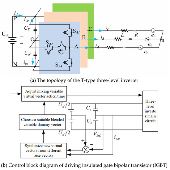
Figure 1.
Topological structure and control block diagram of T-type three-level inverter.
2.2. Analysis of Voltage Vectors for Midpoint Voltage Imbalance
Because each phase of the T-type three-level inverter can output three states—P, O, and N—the three phases together yield 27 switching states, corresponding to 27 basic space voltage vectors. As shown in Figure 2, the space voltage vector diagram can be divided into six major sectors (A, B, C, D, E, and F) based on the angle in the α–β plane. In Figure 2, the 27 basic space voltage vectors are divided into four categories based on their magnitudes: large, medium, small, and zero vectors. The large vectors have a voltage magnitude of 2Udc/3, the medium vectors have a magnitude of Udc/3, the small vectors have a magnitude of Udc/3, and the zero vectors have a magnitude of 0. Each vector type affects the neutral-point voltage differently, and the corresponding neutral-point current for each vector can be determined using the following formula:
where, x represents phases A, B, and C, and 1 indicates the P state, 0 indicates the O state, and −1 indicates the N state.
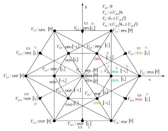
Figure 2.
Space voltage vector diagram.
Taking the medium vector PON as an example, in phase A, the output is in the P state, so current ia does not flow through the neutral point; in phase B, the output is in the O state, meaning current ib flows through the neutral point; and in phase C, the output is in the N state, so current ic does not pass through the neutral point. Therefore, the vector state PON results in a neutral-point current equal to ib. Similarly, the neutral-point currents for other vector states can be determined, as illustrated in the space voltage vector diagram in Figure 2.
As illustrated in Figure 2, taking Sector A as an example, the redundant small vectors generate neutral-point currents that are opposite to each other, and the neutral-point current produced by the medium vector is countered by that from the negative small vector. Analyzing the characteristics and patterns of the space voltage vectors in the T-type three-level inverter reveals that large and zero vectors do not affect the neutral-point voltage, whereas medium and redundant small vectors introduce neutral-point currents that lead to voltage imbalance.
2.3. CMV Problem Analysis
The functional relationship between CMV and switching states is given by
where SA, SB, and SC represent the switching states, with SA, SB, SC ∈ (−1, 0, 1). As seen from the equation, CMV is determined by combining the effect of all three switching states. The CMV values for all 27 switching states are shown in Figure 2.
To suppress CMV, the fundamental vectors used to synthesize virtual vectors should be selected to minimize CMV as much as possible. First, small and medium vectors with zero CMV values are chosen as the fundamental vectors, ensuring that the synthesized virtual vector also has zero CMV. However, relying solely on zero and medium vectors for virtual vector synthesis cannot maintain neutral-point voltage balance across the entire modulation range, and it also degrades the output waveform quality of the inverter. To achieve both effective CMV suppression and high-quality output waveforms, voltage vectors with CMV values of ±Udc/6 and 0 can be incorporated into the synthesis. This expands the set of available fundamental vectors from 7 to 13, ensuring better output voltage quality while controlling CMV within ±Udc/6.
3. Redundant Small Vector VSVPWM
In the VSVPWM modulation method, the small vector is synthesized from redundant small vectors, while the medium vector is synthesized from both redundant small vectors and medium vectors. As shown in Figure 3, the redundant small vectors, medium vectors, and their synthesized virtual vectors are illustrated for Sector A.
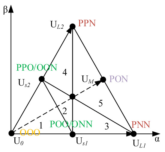
Figure 3.
A large sector, small sector division.
The synthesis formulas for virtual small vectors and virtual medium vectors are given below. In these equations, Us1 and Us2 represent virtual small vectors, while UM represents the virtual medium vector. The virtual medium vector UM is composed of UONN (ia), UPON (ib), and UPPO (ic).
For example, if the reference voltage vector is located in small sector 2, the following expression is satisfied:
4. Hybrid Variable Virtual Space Vector Construction Method
A virtual vector is a composite vector formed by superimposing multiple actual vectors in a specific time proportion. For example, when two or more actual vectors are applied in a time-sharing manner within one modulation cycle, their equivalent effect can be regarded as a “virtual” synthetic vector. Hybrid virtual vectors, however, are not limited to the use of a single virtual vector. Instead, they flexibly select combinations of different virtual vectors according to system requirements (such as neutral-point voltage status, common-mode voltage level, load characteristics, etc.) to achieve multi-objective optimization.
In traditional VSVPWM, the synthesized virtual vectors do not generate neutral-point currents that charge or discharge the DC-side capacitors. While this method can balance the neutral-point voltage, at high modulation indices, the limited regulation capability of redundant small vectors leads to imbalance regions. Additionally, the synthesized vectors exhibit high CMV, and the high switching frequency results in increased switching losses and poor output voltage waveform quality. To address these issues—neutral-point voltage imbalance, high CMV, and excessive switching frequency—this paper proposes an improved hybrid variable virtual vector strategy based on traditional VSVPWM. The major and minor sector divisions remain unchanged, but the virtual small and medium vectors are reconstructed by selecting fundamental vectors with lower CMV. Only fundamental vectors with CMV values of ±Udc/6 and 0 are used for synthesizing virtual small and medium vectors, effectively reducing CMV by half compared to traditional VSVPWM. To ensure neutral-point voltage balance, the neutral-point current must satisfy the following equation within one control cycle:
Note: (x = A, B, C) is the respective voltage vector action time.
To control the neutral-point voltage balance, it is necessary to ensure that the sum of the currents acting on the neutral point within one control cycle is zero. Therefore, the neutral-point current is required to satisfy the following equation:
Note: represents the switching state of phases A, B, and C (where P, O, N correspond to 1, 0, −1 respectively).
- represents the current of phases A, B, C.
- (x = A, B, C) is the respective voltage vector action time.
Taking Sector A as an example, the selection criteria for the fundamental vectors in the hybrid variable virtual space vector modulation method are shown in Figure 4. Based on the conditions that the synthesized vectors must satisfy, the hybrid variable virtual small vector can be synthesized in three ways:
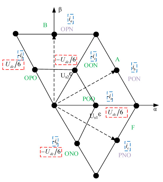
Figure 4.
The selected basic vector distribution map.
- From ONO, POO, and OON
- From PNO and OON
- From ONO and PON.
The synthesized hybrid variable virtual small vectors and virtual medium vectors are listed in Table 1.

Table 1.
Three methods for synthesizing hybrid variable virtual vectors.
The fundamental vector UPNO has a CMV of 0 and a neutral-point current of ic, while the fundamental vector UOON has a CMV of −Udc/6 and a neutral-point current of −ic. Therefore, within one switching period Ts, the total neutral-point current sums to zero, and the synthesized vector has a CMV of −Udc/6. This ensures that the hybrid variable virtual small vector does not affect the neutral-point voltage while maintaining CMV at −Udc/6.
Similarly, for other synthesis methods, the neutral-point voltage remains unaffected, and CMV is maintained at ±Udc/6. Hence, the selection of the hybrid variable virtual small vector synthesis method should be based on an analysis of switching frequency to optimize performance.
As shown in Figure 5, when the reference voltage vector Uref is located within a small sector of Sector A, the synthesis method ➀ produces pulse sequences for five different small sectors, corresponding to 9-step, 11-step, and 13-step schemes. This approach leads to the issue of reusing the same space voltage vector multiple times and the simultaneous switching of two phases. As the number of switching events increases, higher switching losses, reduced system efficiency, and degraded output waveform quality occur. In synthesis method ➁, pulse sequences for five different small sectors correspond to 7-step and 9-step schemes. In this case, each sector pulse sequence experiences large switching state jumps and the simultaneous switching of two phases, leading to a significant increase in the number of switching events, resulting in high switching losses and a reduction in system output efficiency. Synthesis method ➂ uses a unified 9-step pulse sequence for all five small sectors, eliminating the problem of large switching state jumps. In this method, only one phase is switched at a time, which reduces the number of switching events, leading to lower switching losses and improved system output efficiency and waveform quality. Therefore, the preferred synthesis method is ➂, which provides the best performance in terms of efficiency and waveform quality.
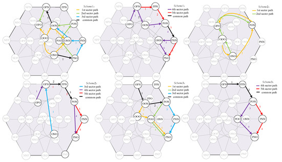
Figure 5.
One-way path diagram of different small sectors in three schemes.
The synthesized hybrid variable virtual medium vector can be derived from Table 1. During the time period Tm when the virtual medium vector is applied, the currents of the three-phase load (ia, ib, ic) are connected to the midpoint O of the voltage divider capacitors at different time intervals. Therefore, the charge flowing into the midpoint O of the voltage divider capacitors from the three-phase load currents can be expressed as follows:
Therefore, during the time period Tm when the hybrid variable virtual medium vector is applied, the conclusions in Table 2 can be derived based on the above equation.
Table 2.
Relationship between k1 coefficient and midpoint charge.
The CMV of the synthesized hybrid variable virtual medium vectors from the fundamental vectors UPNO, UPON, and UOPN is zero. As a result, the CMV of the synthesized hybrid variable virtual medium vector is zero. The fundamental vectors for synthesizing the hybrid variable virtual medium vectors in each sector are listed in Table 3. The definitions of the virtual zero vector and the virtual large vectors and are the same as the definitions of traditional virtual space vectors.
Table 3.
Vector composition of the mixed variable virtual medium of each sector.
Calculation of the Action Time of Virtual Vectors
From the above analysis, any given reference voltage vector can be synthesized using three virtual space vectors based on the Nearest Three Vectors (NTV) principle. Taking the second small sector in Sector A as an example, the reference voltage vector is synthesized from the three virtual vectors , , and . According to the volt-second balance principle, the following equation holds:
In the equation, and represent the duration of the virtual small vectors, while represents the duration of the virtual medium vector. From the above equation, we can derive
The time calculations for other small sectors within Sector A can be derived similarly, as shown in Table 4.
Table 4.
Action time of each small sector virtual space vector in large sector A.
5. Experimental Results
To verify the feasibility of the proposed method, a T-type three-level inverter simulation model was built in MATLAB R2023a/Simulink. Additionally, a physical experimental platform for a three-phase four-wire three-leg T-type three-level energy storage inverter was set up, as shown in Figure 6. The experimental setup included an 30 kW source-load integrated machine, a 15 kW 0–1000 V programmable DC source, a Tektronix multi-channel oscilloscope and a HIOKI 3390 power analyzer, etc.
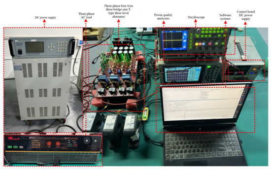
Figure 6.
Three-phase four-wire system and three-bridge arm T-type three-level energy storage inverter experimental platform.
The simulation and experimental test parameters were set as follows:
- DC-side voltage: = 750 v
- Capacitors: C1 = C2 = 480 μF
- Symmetrical three-phase load: R = 10 Ω
- Inverter-side filter inductance: Lf = 500 μH
- Filter capacitance: Cf = 10 μF
- AC output reference frequency: f = 50 Hz
- Sampling period: = 0.0 2 ms.
According to the steady-state experimental results in Figure 7 and Figure 8, the traditional VSVPWM shows a very small voltage difference between the upper and lower capacitors (around 0.2 V), and the CMV ranges from approximately ±250 v (). In contrast, the hybrid variable VSVPWM exhibits an even smaller capacitor voltage difference (around 0.1 V), with the CMV limited to about ±125 v (). Thus, while both VSVPWM methods can control the neutral-point voltage, the CMV generated by the hybrid variable VSVPWM is only half that of the traditional VSVPWM. As analyzed earlier, the fundamental vectors chosen in traditional VSVPWM have higher CMV values compared to those selected in the hybrid variable method, resulting in greater CMV in the synthesized vectors. Overall, the advantages of the hybrid variable VSVPWM over the traditional VSVPWM are much more pronounced.
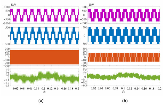
Figure 7.
m = 0.8 (a): UAB line voltage of VSVPWM, UA phase voltage, UCMV common-mode voltage, UCN capacitance difference (b): UAB line voltage of hybrid variable VSVPWM, UA phase voltage, UCMV common-mode voltage, UCN capacitance difference.
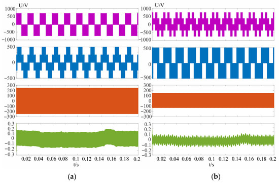
Figure 8.
m = 0.3 (a): UAB line voltage of VSVPWM, UA phase voltage, UCMV common-mode voltage, UCN capacitance difference (b): UAB line voltage of hybrid variable VSVPWM, UA phase voltage, UCMV common-mode voltage, UCN capacitance difference.
According to the dynamic experimental results shown in Figure 9 and Figure 10, when the modulation index m changes abruptly, the hybrid variable VSVPWM exhibits lower AC ripple and a smaller DC offset in the neutral-point voltage. Overall, its control performance is superior to that of the traditional VSVPWM. In Figure 11, under a 50% unbalanced load condition and with the DC bus voltage set at 800 V, the output voltage of the energy storage inverter and the fluctuations of the bus capacitors are presented. It can be observed that the proposed hybrid variable VSVPWM maintains a capacitor voltage difference within ±5 V under different modulation indices, which is a marked improvement over the traditional VSVPWM under unbalanced load conditions. This validates the adaptability of the proposed algorithm. Furthermore, Figure 12 displays the FFT analysis spectra of the current for both methods under identical hardware conditions. The comparison indicates that, while the proposed hybrid virtual vector algorithm effectively provides neutral-point balancing and common-mode voltage suppression, it has a minimal impact on the output harmonics.
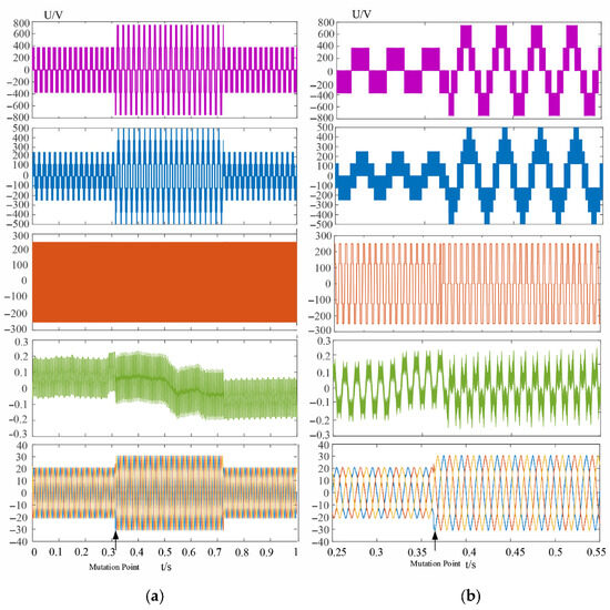
Figure 9.
m = 0.3 to 0.6 (a): UAB line voltage of VSVPWM, UA phase voltage, UCMV common-mode voltage, UCN capacitance difference, iABC three-phase current dynamic diagram (b): Mutation part.
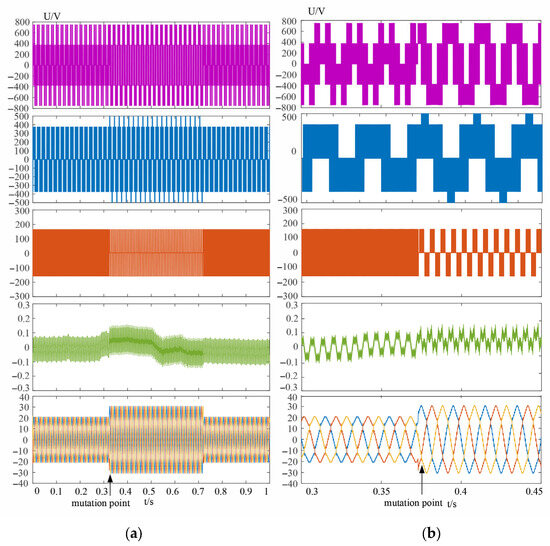
Figure 10.
m = 0.3 to 0.6 (a): UAB line voltage of hybrid variable VSVPWM, UA phase voltage, UCMV common-mode voltage, UCN capacitance difference, iABC three-phase current dynamic diagram (b): Mutation part.
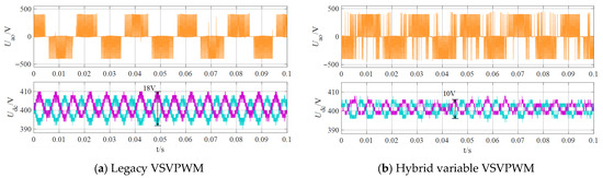
Figure 11.
Dynamic test waveform on the DC side under 50% unbalanced load.
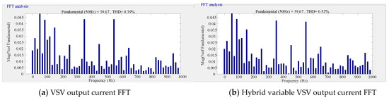
Figure 12.
Output current harmonic analysis.
Table 5 presents the efficiency, THD, and midpoint voltage fluctuation of different PWM modulation methods. It can be seen from the table that under different output power tests, the proposed hybrid variable VSVPWM method achieves a better midpoint voltage fluctuation suppression effect compared to VSVPWM, with little difference in efficiency and THD.
Table 5.
The efficiency, THD and midpoint voltage fluctuation of two PWM modulation methods.
6. Conclusions
This paper has proposed a hybrid variable VSVPWM modulation method for neutral-point voltage balancing specifically designed for the T-type three-level energy storage inverter topology, and its effectiveness was validated through both simulation and physical experiments. The main conclusions are as follows:
- Analysis of the voltage space vectors in the T-type three-level energy storage inverter revealed that the zero vector and all medium vectors generate zero common-mode voltage (CMV). However, synthesizing the reference voltage vector using only zero and medium vectors led to adverse effects. Therefore, vectors that either produce opposite neutral-point currents or yield a net zero current, and which also exhibit low CMV, were incorporated into the synthesis. In this regard, the virtual vectors were reconstructed by combining adjacent medium and small vectors that produce opposing neutral-point currents to form a hybrid variable virtual small vector, and by synthesizing three neighboring medium vectors to form a hybrid variable virtual medium vector.
- The traditional VSVPWM modulation method for the T-type three-level energy storage inverter suffers from neutral-point voltage imbalance at high modulation indices. To address this, a hybrid variable virtual vector approach, which combines virtual small and medium vectors, has been proposed. This method achieved neutral-point voltage balancing across the entire modulation range, while maintaining a low switching frequency and minimizing CMV to . Physical experiments also confirmed that, across the full modulation range and even under unbalanced load conditions, the proposed algorithm delivers excellent control performance, demonstrating significant practical engineering value.
Author Contributions
Methodology, Z.M.; Software, J.L.; Formal analysis, Z.M.; Investigation, K.X.; Data curation, K.X.; Writing—original draft, Z.M.; Writing—review & editing, J.L. All authors have read and agreed to the published version of the manuscript.
Funding
The work described in this paper was fully supported by Excellent Young and Middle-Aged Science and Technology Innovation Teams in Hubei Province’s Universities (T2024043); Funded Project of Yunnan Water Resources and Hydropower Vocational College (2025YSZSYS013); Hubei Provincial Science and Technology Plan Project (2024ELA011); Engineering Research Center of Agricultural Intelligent Technology, Ministry of Education (ERCITA-KF004); Hubei Provincial Engineering Research Center for Intelligent Detection and Identineutral poinyfication of Complex Parts (IDICP-KF-2024-06); Intelligent manufacturing Hubei Province characteristic advantage discipline group (202207).
Data Availability Statement
Data are contained within the article.
Conflicts of Interest
The authors declare no conflict of interest.
References
- Huang, J.; Lin, X.; Sun, J.; Xu, H. A Stabilization Control Strategy for Wind Energy Storage Microgrid Based on Improved Virtual Synchronous Generator. Energies 2024, 17, 2567. [Google Scholar] [CrossRef]
- Yu, C.; Xia, Y.; Shi, S. Research on control of single-phase photovoltaic energy storage grid-connected inverter. Proc. SPIE 2024, 12987, 8. [Google Scholar]
- Liu, D.; Zou, C.; Li, X.; Lin, B.; Liu, J.; Jin, T. Suppression of continuous commutation failure in LCC-HVDC transmission based on improved virtual synchronous generator control for energy storage system. Int. J. Electr. Power Energy Syst. 2024, 159, 110018. [Google Scholar] [CrossRef]
- Ma, X.; Jia, R.; Liang, C.; Xu, R. Multi-Stage Optimal Power Control Method for Distribution Network with Photovoltaic and Energy Storage Considering Grouping Cooperation. Electronics 2024, 13, 3415. [Google Scholar] [CrossRef]
- Ju, Y.; Zhang, H.; Cao, X.; Zhang, R.; Ji, L.; Wei, X.; Liu, Y. Research on Grid-Connected and Off-Grid Control Strategy for Bidirectional Energy Storage Inverter. Electronics 2024, 13, 4911. [Google Scholar] [CrossRef]
- Hou, H.; Liu, S.; Li, Z.; Xia, S. Research on the Energy Storage System of Flying Wheels Based on Model Prediction Current Control. In The Proceedings of the 18th Annual Conference of China Electrotechnical Society; Springer: Singapore, 2024. [Google Scholar]
- Zharkov, M.A.; Sarakhanova, R.Y.; Kharitonov, S.A. New electric starter system based on on-board power network with hydrogen energy storage. Int. J. Hydrogen Energy 2024, 85, 385–393. [Google Scholar] [CrossRef]
- Zhao, C.; Hao, Z.; Zhang, J.; Zhang, Y. Research on the improved ptosis control strategy based on energy storage converter. Power Electron. Technol. 2024, 58, 69–73+77. [Google Scholar]
- Zhang, L.; Xu, F.; Zhu, T.; Zuo, Z.; Zhang, S. Optimized control of grid-connected inverter based on fuzzy adaptation. Electron. Des. Eng. 2024, 32, 71–76+81. [Google Scholar]
- Shi, J.; Hu, S.; Fu, R.; Zhang, Q. Convex Optimization and PV Inverter Control Strategy-Based Research on Active Distribution Networks. Energies 2025, 18, 1793. [Google Scholar] [CrossRef]
- Selim, F.; Aly, M.; Megahed, T.F.; Shoyama, M.; Abdelkader, S.M. Model Predictive Controlled Parallel Photovoltaic-Battery Inverters Supporting Weak Grid Environment. Sustainability 2024, 16, 7261. [Google Scholar] [CrossRef]
- Zhong, W.; Mu, M.; Gai, P.; Li, P.; Gao, H.; Chen, J.; Zhang, K. Voltage Control Strategy of Distribution Networks with Photovoltaic and Energy Storage Considering Battery Lifetime Based on Deep Reinforcement Learning. In The Proceedings of the 11th Frontier Academic Forum of Electrical Engineering; Springer: Singapore, 2025. [Google Scholar]
- Nong, B. Research on the Control Strategy of Photovoltaic Power Generation System with Hybrid Energy Storage. Master’s Thesis, Guizhou University, Guiyang, China, 2024. [Google Scholar]
- Bai, B. Research on the Control Strategy of Optical Storage and DC Micro-Grid Based on Virtual Motor Control. Master’s Thesis, Northern University for Nationalities, Yinchuan, China, 2024. [Google Scholar]
- Li, S.; Liu, B.; Li, H.; Li, X. Based on the consistency algorithm, photovoltaic inverter and energy storage group coordination voltage control strategy. J. Sol. Energy 2024, 45, 345–352. [Google Scholar]
- Zhou, C.; Wang, N.; Ni, F.; Zhang, W. Grid-Connected/Islanded Switching Control Strategy for Photovoltaic Storage Hybrid Inverters Based on Modified Chimpanzee Optimization Algorithm. Energy Eng. 2025, 122, 265. [Google Scholar] [CrossRef]
- Liu, X. Research on the Control Strategy of the Landscape Storage Inverter System Based on VSG. Master’s Thesis, Lanzhou Jiaotong University, Lanzhou, China, 2023. [Google Scholar]
- Zhu, M.; Zhou, G.; Guo, L.; Song, N.; Wang, Y.; Lv, H.; Chu, S. Energy Storage Converter Off-Grid Parallel Cooperative Control Based on CAN Bus. Electronics 2025, 14, 2010. [Google Scholar] [CrossRef]
- Li, Z. Photovoltaic Grid-Connected Virtual Synchronous Machine Control and Oscillation Suppression Strategy. Master’s Thesis, Shenyang University of Technology, Shenyang, China, 2023. [Google Scholar]
- Wu, X. Research on the Inverter Control Strategy of Photovoltaic MPPT and VSG Based on the Full-Order Terminal Sliding Mode. Master’s Thesis, Harbin University of Science and Technology, Harbin, China, 2023. [Google Scholar]
- Zheng, Y.; Xu, Y.; Yang, Y.; Hua, L.; Yang, Y. Application of adaptive virtual synchronous generator based on improved active power loop in photovoltaic storage systems. Front. Energy Res. 2025, 12, 1468629. [Google Scholar] [CrossRef]
- Dai, Y.; Yu, A.Q. New energy storage type UPS system and its control method. Power Electron. Technol. 2022, 56, 64–68. [Google Scholar]
Disclaimer/Publisher’s Note: The statements, opinions and data contained in all publications are solely those of the individual author(s) and contributor(s) and not of MDPI and/or the editor(s). MDPI and/or the editor(s) disclaim responsibility for any injury to people or property resulting from any ideas, methods, instructions or products referred to in the content. |
© 2025 by the authors. Licensee MDPI, Basel, Switzerland. This article is an open access article distributed under the terms and conditions of the Creative Commons Attribution (CC BY) license (https://creativecommons.org/licenses/by/4.0/).