Abstract
To meet the demands for weight reduction and cost efficiency, the design of interior permanent magnet synchronous motors (IPMSMs) for electric vehicles is inevitably evolving toward high-speed operation, compactness, and improved efficiency. This paper proposes and analyzes a novel hybrid winding design that combines hair-pin coils and litz wire coils. The objective of this hybrid approach is to leverage the high-fill-factor advantage of hair-pin windings while mitigating the increased high-frequency copper losses caused by skin effect—an area where litz wire excels. Finite element analysis (FEA) is used to evaluate and compare the performance of the proposed hybrid stator design against conventional winding configurations, including round wire windings and pure rectangular windings. Key factors such as fill factor and skin effect are thoroughly considered in the analysis. Additionally, a system-level evaluation is conducted based on assumed electric vehicle parameters, providing a comprehensive assessment of efficiency and energy losses under real-world operating conditions.
Keywords:
electric motor; IPMSM; litz wire; hair-pin winding; skin effect; proximity effect; permanent magnets 1. Introduction
With the rapid development of the electric vehicle (EV) industry, traction motors are facing increasingly stringent requirements in terms of power density, compactness, manufacturing cost, and energy efficiency. Among various motor technologies, interior permanent magnet synchronous motors (IPMSMs) have emerged as one of the most promising choices for EV propulsion due to their high torque density, excellent field-weakening capability, and high efficiency over a wide speed range [1,2,3,4]. To meet the evolving demands of EVs, IPMSM design is trending toward high-speed, compact, and lightweight configurations. However, high-speed operation brings challenges in terms of alternating current (AC) losses, particularly in the stator windings, where skin and proximity effects become significant at elevated frequencies. In this context, the choice and configuration of stator windings play a crucial role in determining overall motor performance, thermal behavior, and manufacturing feasibility. Hair-pin windings, composed of rectangular solid conductors, offer several benefits including a high slot fill factor, good thermal conductivity, and compatibility with automated production lines [5,6,7]. These attributes make them a popular choice in modern EV traction motors. However, under high-frequency conditions, the solid nature of hair-pin conductors makes them more susceptible to skin effect and proximity effect, leading to increased AC resistance and copper losses [8,9,10]. Conversely, litz wire—formed by bundling many fine, insulated strands in a specific transposition pattern—is designed specifically to mitigate high-frequency AC losses. It achieves this by ensuring a more uniform current distribution among strands, effectively reducing both skin and proximity effects [11]. In prior research, several studies have sought to further expand the benefits of litz wire. Specifically, refs. [12,13,14] investigated the characteristics and application potential of aluminum-based litz wires, while refs. [13,15] focused on the optimization of litz wire designs for use in traction motors and aerospace electrical machines.
Nevertheless, litz wire has disadvantages, such as a low slot fill factor, complex winding processes, and reduced mechanical rigidity, which pose limitations for high-volume EV motor manufacturing [16]. To address the above limitations, this paper proposes a novel hybrid winding structure that combines the advantages of both hair-pin and litz wire conductors. The hybrid design strategically employs each conductor type in regions where its characteristics are most effective—leveraging hair-pin for high slot utilization and thermal management, and litz wire for loss reduction in areas of high-frequency current concentration. The design is based on detailed electromagnetic analysis and optimization, with winding type allocation guided by finite element method (FEM) simulations. Following the electromagnetic optimization, four IPMSM models are established: a conventional round wire model, a pure hair-pin model, the proposed hybrid hair-pin/litz wire model, and a pure litz wire model. In the second section, the design parameters and structural configurations of these four models are defined and standardized for fair comparison. Section 3 compares the no-load and load characteristics of the different models based on FEM simulations, while Section 4 evaluates electromagnetic losses and system-level efficiency under real-world electric vehicle driving conditions. Performance metrics such as copper loss, slot fill factor, and energy consumption are analyzed in depth. The simulation results demonstrate that the hybrid winding structure offers a compelling balance between manufacturability and performance. The hybrid design reduces AC copper losses without sacrificing fill factor and DC resistance. Overall, this research confirms the feasibility and practicality of a hybrid winding strategy for IPMSMs and offers new insights for the next generation of high-performance EV motors. The final section of the paper concludes the findings and outlines directions for future work.
2. Fundamental Characteristics of Winding Types in EV Traction Motors
In the design of EV traction motors, the choice of conductor type is a critical decision that directly impacts the system’s electrical efficiency, thermal performance, manufacturing complexity, and ultimately, overall reliability and cost. Currently, the three most commonly used conductor types are traditional round enameled wire, rectangular wire (hair-pin), and litz wire, which is typically used in high-frequency applications. This section provides a qualitative and structural comparison of these three conductor types, focusing on their insulation characteristics, manufacturing complexity, and application suitability. The cross-sectional geometry of a conductor directly determines its slot fill factor, AC loss characteristics, and thermal contact area with the stator core. Rectangular wire offers excellent slot fill and good mechanical rigidity; however, due to sharp corners that can lead to electric field concentration, it typically requires a thicker insulation layer. This is especially important in high-voltage platforms (800 V), where corona-resistant enamel insulation is necessary. Round wire has a simple structure with uniform insulation coverage and is suitable for conventional random windings, though it generally results in lower space utilization. Litz wire is composed of multiple fine strands, each individually insulated, which significantly reduces high-frequency losses. However, its overall structure is complex, the fill factor is relatively low, and termination can be challenging [17]. Figure 1 shows the typical cross-sectional structures of these three conductor types, illustrating their basic geometries and insulation arrangements. Their advantages, disadvantages, and comparison details have been added to Table 1.

Figure 1.
Typical cross-sectional structures of common conductor types used in EV traction motors for 800 V platforms.

Table 1.
Comparison of common winding types in electrical machines: fill factors, advantages, and limitations.
2.1. Basic Characteristics of Litz Wire
Litz wire is composed of numerous individually insulated copper strands, which are twisted or woven together in a uniform pattern. In certain litz constructions, twisted bundles are interconnected with other bundles, and all are subsequently twisted together to form the final conductor.
In high-frequency litz wire design, two critical parameters—strand pitch and strand-level copper fill factor—jointly govern electrical performance, spatial efficiency, and thermal behavior. The strand pitch, defined as the axial length over which a strand completes a full helical turn, directly affects the electromagnetic symmetry among strands. A shorter pitch promotes uniform exposure to magnetic fields across the conductor cross-section, thereby reducing proximity-effect-induced current crowding. The corresponding total transposition length can be expressed as the least common multiple of the individual lay lengths:
These principles are in line with Sullivan’s analytical framework [18], which demonstrates the importance of pitch and strand geometry in optimizing litz wire performance.
On the other hand, the strand-level fill factor ηs, defined as the ratio between copper area and total strand area (including insulation), determines how efficiently copper occupies space within each insulated strand:
where Ac is copper conductor area and At is the total cross-sectional area of a single insulated strand (including the copper conductor and its insulation). The overall copper utilization of a litz wire bundle can then be expressed as the bundle-level copper packing factor ηlitz, which accounts for both the strand-level copper fill factor and the spatial packing efficiency of strands in the bundle [18,19]:
where n is the number of strands in the litz wire bundle and Abundle is the cross-sectional area of the overall litz wire envelope (typically circular or elliptical in shape). The term ηp represents the strand packing efficiency within the bundle.
A higher fill factor reduces DC resistance and enhances thermal conductivity, making it highly desirable for compact and high-performance designs. In recent years, significant progress has been made in conductor compression and forming technologies, particularly those applied to rectangular litz wire structures, which have greatly improved strand-level packing density. By applying mechanical or thermoplastic compression during the manufacturing process, manufacturers can effectively reduce interstitial air gaps, achieving strand-level fill factors as high as 60–75%.
In addition, rolling equipment can be used to apply strong compression to shape conventional litz wire into rectangular litz wire (also known as shaped litz wire). This process not only increases the overall fill factor of the litz wire, but also improves the efficiency of the coil winding process. Specifically, bundled litz wire with a circular cross-section is fed into a rolling machine at a controlled feed rate. The machine is equipped with rollers that apply a defined contact pressure, transforming the twisted circular profile into a rectangular cross-section. This process is illustrated in Figure 2.
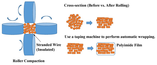
Figure 2.
Rectangularization process of litz wire using high-compression rolling equipment.
Compared to the 40–55% efficiency achieved in conventional round wire constructions, this development significantly enhances volumetric copper efficiency, particularly in space-constrained and high-frequency applications such as resonant converters, high-speed motors, and planar magnetics. Therefore, maximizing strand fill factor—while co-optimizing pitch to mitigate AC losses—has become a key strategy in modern litz wire engineering.
2.2. Basic Characteristics of Hybrid Hair-Pin and Litz Wire Windings
In electric machines, the spatial position of windings within the stator slot significantly affects the AC copper loss. Specifically, coils located near the air gap are subjected to stronger time-varying magnetic fields due to the steep magnetic flux gradient across the high-reluctance air gap. This results in a more pronounced skin effect and proximity effect, leading to increased AC resistance and higher local losses. The equivalent AC resistance can be expressed as [20]
Here, δ is the skin depth, which decreases as frequency and magnetic field strength increase, especially near the air gap. The proximity effect coefficient kprox also increases with local AC magnetic field intensity Bac. In contrast, windings located farther from the air gap experience weaker magnetic fields, more uniform current distribution, and, thus, lower AC copper losses. These factors highlight the importance of minimizing AC losses in coils near the air gap, particularly in high-frequency or high-efficiency motor designs. Figure 3a illustrates the design concept of a hybrid winding using litz and rectangular wires. To mitigate the skin effect near the air gap, litz wire is utilized in the first and second coil layers, which are positioned closest to the air gap, where high-frequency magnetic fields are most concentrated. The remaining layers—third through eighth—are located farther from the air gap and are wound with rectangular conductors, as exemplified by the eight-layer winding configuration used in this study. The wire diameter is selected based on a trade-off between high-frequency skin depth, mechanical manufacturability, and slot fill factor. Smaller diameters reduce skin effect losses but may increase winding complexity. This selection process ensures both electromagnetic performance and manufacturing feasibility. While a higher fill factor enhances slot utilization and reduces DC resistance, excessive compaction of litz wire bundles may compromise mechanical integrity, leading to deformation, increased insertion difficulty, and potential structural failure during motor operation. To mitigate these risks, a practical trade-off was established through iterative prototyping and validation, ensuring an optimal balance between electromagnetic efficiency and mechanical robustness. This balance is critical for maintaining process reliability and ensuring long-term durability of the motor. Figure 3b shows the 3D structure of the stator. During the design process, the insertion and stacking sequence of the coils must be carefully considered. Additionally, to improve mass production feasibility, the number of solder joints between the litz wires and rectangular wires should be minimized. Additionally, during the soldering process, it is common for the fine strands of the litz wire to have weak bonding with the rectangular wire, which may lead to disconnection or detachment. To improve joint reliability, the assembly process can include (1) pressing the wires together to ensure close contact, (2) resistance welding as an alternative or supplement to soldering. In certain applications, a clamp-style (snap-fit) mechanical connection can also be considered to further enhance connection stability; however, when applied over polymer-coated litz wires, poor contact resistance may occur if insulation is not properly removed. For litz wires, insulation removal is more complex due to the individually coated fine strands. Industrial techniques such as laser stripping or chemical stripping are typically employed to ensure consistent exposure of bare copper before crimping or soldering, which helps secure low-resistance electrical contact. In future work, the impact of insulation removal techniques and crimping quality on contact resistance will be further evaluated.
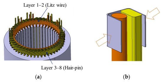
Figure 3.
Hybrid coil interconnection strategy and connection reliability considerations. (a) Schematic of coil transition between hair-pin wire and litz wire in hybrid winding (8-layer concept). (b) Potential failure point due to weak soldering between fine litz strands and rectangular wire; snap-fit structure proposed as alternative.
3. Configuration and Specification
The target three-phase interior permanent magnet synchronous motor (IPMSM) has a rated power of 130 kW, a base speed of 5000 r/min, and a rated torque of 180 N·m. The IPMSM adopts a “double U-shaped” permanent magnet (PM) rotor structure, as shown in Table 2, to enhance starting torque [21]. The ribs and bridges within the rotor have undergone mechanical strength analysis to ensure structural integrity during high-speed operation.

Table 2.
Main parameters of rotor.
The baseline motor design features a 48-slot, eight-pole configuration with distributed windings to reduce electromagnetic harmonics. This study compares two typical industrial stator slot designs: pear-shaped slots and rectangular (square) slots. For the rectangular slot design, three different rectangular wire arrangements are analyzed and compared. Figure 4 shows the cross-sectional views of two stator slot and coil combinations.
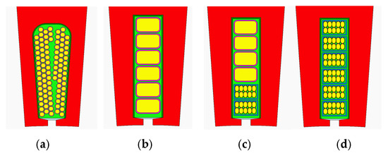
Figure 4.
Stator slot and coil configurations of models 1–4. (a) Model 1: Pear-shaped slot with round wire winding (baseline design); (b) model 2: rectangular slot with rectangular wire winding; (c) model 3: rectangular slot with partial rectangular litz wire (Layer 1); (d) model 4: rectangular slot with full rectangular litz wire.
In model 1, the stator adopts a parallel tooth structure with pear-shaped slots and conventional round wire windings. This configuration serves as a baseline design with a simple winding layout. Model 2 retains the parallel slot structure but replaces the round wire with rectangular wire to maximize the slot fill factor, thereby improving electromagnetic utilization and winding density. Model 3 shares the same parallel slot design as model 2 but uses a more specialized winding structure. In the slot opening region near the air gap (Layer 1), high-strength compressed rectangular litz wire is employed. This design aims to reduce AC losses and improve electromagnetic performance under high-speed operation, especially in regions with strong magnetic field variation. Model 4 adopts high-strength compressed rectangular litz wire throughout.
Multiple factors were considered in the comparison, including cogging torque, no-load back electromotive force (B-EMF), efficiency at the rated operating point, and torque ripple requirements. The analysis conditions for the comparison are as follows.
- All four models share identical rotor specifications, including segmented permanent magnets and core materials.
- Appropriate copper wire diameters (round wire) and suitably sized rectangular wires (in width and height) were selected to ensure that the stator copper weight of the four models was as similar as possible. The fill factors of the four models were also verified.
- All models were analyzed using the two-dimensional finite element method (2D FEM) to ensure accurate comparison results. Considering different levels of core saturation in each model, the current angle at the maximum torque per ampere (MTPA) point had to be determined to fairly compare performance across all designs [22].
Table 3 summarizes the relevant electrical and geometric parameters of the four stator models. The phase resistance of each model was calculated using ANSYS RMxprt.

Table 3.
Electrical and geometric parameters of the four stator models.
3.1. Open-Circuit Analysis of Model
The line-to-line no-load back electromotive force (B-EMF) characteristics of the four models are shown in Figure 5a. And these value s were calculated using Equation (6).
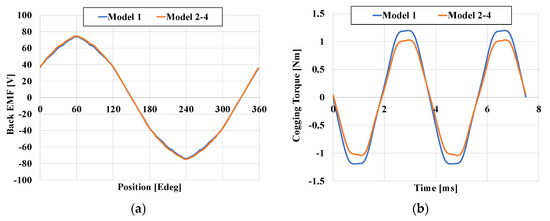
Figure 5.
(a) The line-to-line B-EMF of the four models. (b) The cogging torque of the four models.
The B-EMF can be expressed as a function of the rotor speed (ωm), the effective magnetic flux linkage (Φp), the total number of coils turns (N), the B-EMF constant (Ke), and the number of parallel branches (a). Since all motor models utilize identical rotor geometry and an equal number of winding turns, they generate equivalent B-EMF under no-load conditions.
Figure 5b compares the cogging torque characteristics across the four motor designs. This type of torque arises due to variations in magnetic reluctance between the permanent magnets on the rotor and the stator core. Its magnitude depends on the magnetic flux linkage and is inversely related to the air-gap width. The cogging torque can be estimated using the following expression:
In this equation, Φg represents the magnetic flux passing through the air gap, while R denotes the corresponding magnetic reluctance. Applying this concept, it can be observed that in comparison to model 1, models 2 to 4 have significantly smaller stator parallel slot areas than the pear-shaped slots. As a result, the magnetic saturation in the teeth of models 2 to 4 is noticeably lower than in model 1, leading to a reduction in cogging torque. Specifically, the cogging torque of model 1 accounts for approximately 1.13% of the nominal torque, while that of models 2 to 4 is around 1.02%.
3.2. Load Operation Analysis
The electromagnetic torque of each model was analyzed under ideal sinusoidal current conditions. To ensure a fair performance comparison, it is essential to determine the optimal current phase angle corresponding to the maximum torque per ampere (MTPA) operating point, considering the influence of core saturation. Table 4 summarizes the MTPA-related data at the nominal speed of 5000 r/min.

Table 4.
Two-dimensional FEM analysis result.
Figure 6 illustrates the electromagnetic torque characteristics of the four models, while Figure 7 presents the magnetic field distribution under load conditions. It is worth noting that only model 1’s stator lamination structure differs from that of the other three models.

Figure 6.
(a) FEM torque value and torque ripple at different current angles (phase current Ia: 200 Arms, speed: 5000 r/min). (b) FEM torque waveform at rated operating point (current angle model 1, β: 40° model 2–4, β: 38°).
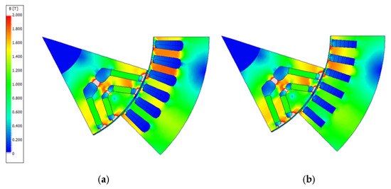
Figure 7.
Cross-section and flux density distributions of four models in MPTA conditions. (a) Model 1, load condition (Ia: 200 Arms; β: 40°). (b) Models 2–4, load condition (Ia: 200 Arms; β: 38°).
Consequently, similar to the no-load condition, the IPMSM’s core saturation under load operation is different for model 1 compared to models 2–4, while models 2 and 4 exhibit identical saturation levels (as shown in Figure 7). Therefore, the MTPA current angles of model 1 and models 2–4 are not the same. Moreover, the torque ripple is quantified by the torque ripple factor, which represents the ratio between the maximum fluctuation (peak-to-peak torque) and the mean torque output. This metric provides a standard way to evaluate the severity of torque variation. The mathematical definition is expressed as
Due to the influence of the no-load cogging torque in the air-gap magnetic field, harmonics are introduced, which are derived from the slotting and pole structure caused by high-magnetomotive-force space harmonics. As a result, model 1 generates a large torque ripple. At a given moment, the distribution of tangential electromagnetic stress on the rotor surface—induced by harmonic components of the magnetic field (denoted by “v”)—can be described along the circumferential direction of the air-gap as
where Bθv and Brv are the harmonic field magnitudes and φdv is the angle between the two components.
Figure 8 compares the torque characteristics of different models at various speeds. The analysis indicates that, due to the higher slot fill factor and lower magnetic saturation in the stator teeth, models 2 to 4 achieve the highest base torque (202.6 Nm).
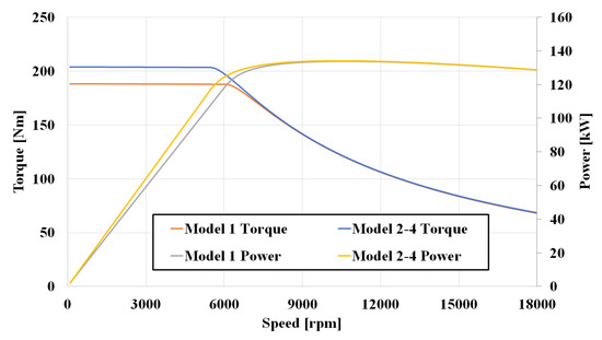
Figure 8.
Comparison of torque and power according to speed.
However, in the high-speed field-weakening and maximum torque per voltage (MTPV) control regions, all models exhibit similar torque behavior due to the overall decline in magnetic flux density in the stator core. Additionally, because the rotor structures are identical, the torque values at high speeds converge across all models. Therefore, at the base speed of around 5000 r/min, Model 1 delivers a power output of 98.6 kW, while Models 2–4 achieve 105.8 kW. However, across the full speed range, all models reach a maximum power of 134 kW, occurring near the 10,500 r/min range.
4. Comparison of Copper Loss, Efficiency Maps, and WLTP Class 3 Driving Cycle
Figure 9 presents the current density for model 1 and model 2 at both base speed (5000 r/min) and maximum speed (18,000 r/min). It can be clearly observed that the current density at maximum speed is significantly higher than at base speed. Additionally, model 2 exhibits substantially higher skin effect and proximity effect losses compared to model 1, especially at high speeds, where the copper losses in model 2 are significantly greater than those in model 1. Furthermore, in both models, coil losses are notably higher near the air gap, with the current density in coils closer to the air gap being significantly higher than in coils farther from the air gap. Figure 10 illustrates the ratio of AC copper losses to DC copper losses in the coils of both slots (the motor has 48 slots and eight poles, with 2 slots per phase per pole). At higher speeds, AC losses, such as those caused by skin and proximity effects, become increasingly significant, leading to a higher AC-to-DC copper loss ratio. In contrast, under base speed conditions, these high-frequency effects are less dominant, and DC losses account for a larger proportion of the total copper loss. This explains the noticeable difference in the coil loss distribution patterns across the rows in Figure 10. Finally, it can be observed that the AC-to-DC copper loss ratio increases significantly in the coils closer to the air gap.
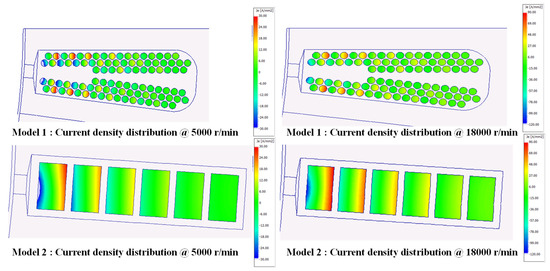
Figure 9.
Comparison of ac copper loss and dc copper loss ratios in model 1 and model 2 at base speed (5000 r/min) and maximum speed (18,000 r/min).

Figure 10.
AC-to-DC copper loss ratio in coils of model 2 at base and maximum speed (DC copper loss of each conductor normalized to 1).
Subsequently, in ANSYS Maxwell, the litz rectangular wire used in Models 3 and 4 is simulated using the bulk conductor combined with an equivalent AC resistance model. Rather than modeling each individual strand, the entire litz wire is treated as a compressed, unified volume conductor, with current source excitation applied. In practice, fully modeling the litz wire—including all individual strands and their precise coil arrangement—would require substantial modeling and setup time, which is difficult to accurately estimate. Moreover, such detailed simulations would consume extensive memory resources, making it practically impossible to perform multi-point simulations, such as efficiency map generation. Therefore, an equivalent resistance approach was adopted to simplify the model and significantly reduce computational complexity. To reflect practical manufacturing effects such as twisting, forming deformation, contact resistance, and insulation layer variations, an empirical correction factor—referred to as the twisting length correction factor—is applied. This factor was derived from coil-level measurements, where the measured DC resistance of individual prototype coils was found to be approximately 1.05 to 1.07 times higher than the theoretical value. Accordingly, this correction factor is incorporated into the simulation by adjusting the coil material properties to reflect increased effective DC resistance. This approach effectively reduces model complexity, as there is no need to model each individual enamel-coated wire as a separate entity, thereby significantly reducing computational effort. Table 5 presents the DC copper loss and high-frequency copper loss components for all four models. Figure 11 illustrates the variation in AC loss with speed for each model. In particular, models 3 (hybrid winding) and 4 (litz wire winding) include the calculated results of stranded AC losses.

Table 5.
DC and high-frequency copper loss comparison for the four winding models.

Figure 11.
AC loss variation with speed including stranded losses in hybrid and litz wire models @ 60 Nm.
The results indicate that by utilizing a combination of hair-pin rectangular wire and litz wire, copper losses at high speeds can be significantly reduced. Furthermore, by using only 1–2 layers of litz rectangular wire near the air gap, the increase in DC copper losses remains minimal. Lastly, model 4, by employing full litz wire, significantly reduces AC copper losses at high speeds. However, the excessive use of litz wire reduces the slot fill factor, leading to a substantial increase in DC copper losses. Figure 12 presents the efficiency maps for all four models.
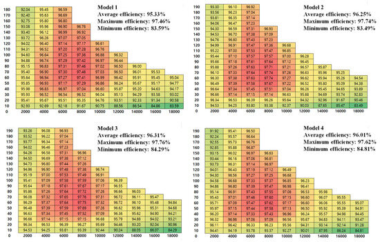
Figure 12.
Efficiency maps of the four models under a DC voltage of 550 V and a motor temperature of 60 °C. Mechanical losses are not included.
It should be noted that model 3 achieves a peak efficiency of 97.76%, with a broad 97% efficiency contour covering the speed range from 4000 r/min to 10,000 r/min. The high-efficiency region is primarily located in the low-to-medium torque range, which aligns closely with the typical vehicle drive cycle residency area.
The four motor models were subsequently evaluated based on their total energy consumption during a complete driving cycle, specifically referencing the Worldwide Harmonized Light Vehicles Test Procedure (WLTP) Class 3. This standardized cycle is tailored for high-performance electric vehicles capable of exceeding 130 km/h in top speed [23,24,25]. Motor speed, torque demand, and power output throughout the WLTP scenario are illustrated in Figure 13, and detailed vehicle specifications can be found in Appendix A.
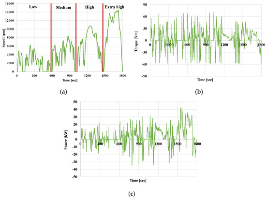
Figure 13.
(a) Motor speed, (b) absolute load torque, and (c) power over the WLTP Class 3 driving cycle.
Figure 14 shows the motor’s peak torque versus speed map. It can be observed that the entire WLTP Class 3 duty cycle remains within the motor’s defined torque–speed operating envelope. Consequently, provided that the motor satisfies both continuous and transient overload torque demands, it can successfully support full compliance with the WLTP Class 3 profile.
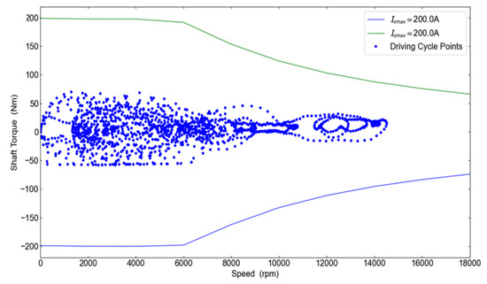
Figure 14.
EV propulsion motor specification for peak torque versus speed characteristics (model 2–4).
To facilitate a rapid comparison of the four motor models under the WLTP Class 3 driving cycle, it is observed that the majority of operating points are concentrated in the region of 50 Nm/15,000 r/min. Therefore, the average efficiencies of the four models within this torque–speed range are calculated and presented in Table 6, indicating that model 3 exhibits the highest efficiency among all. As illustrated in Appendix A, the relevant vehicle adopts a relatively large gear reduction ratio, which offers the advantage of reducing the required motor torque and enabling a more compact motor design. Given that traction motors typically operate at high speeds with relatively low torque output, a higher gear ratio allows the conversion of high motor speed into higher wheel-end torque, thereby improving vehicle launch, gradeability, and low-speed acceleration performance.

Table 6.
Comparison of average efficiency of four motor models under different operating conditions.
Nevertheless, the motor’s performance under lower gear reduction ratios must also be considered. To evaluate efficiency in such scenarios, attention is directed to the high-torque, low-speed operating region. Accordingly, Table 6 also includes the average efficiencies of the four models in the 90 Nm/8000 r/min range. While model 3 continues to demonstrate the highest efficiency in this region, the margin of improvement over model 2 is notably smaller. This phenomenon is primarily attributed to the hybrid winding structure of model 3, which combines rectangular wire and litz wire. This design significantly reduces AC copper losses compared to the rectangular-wire-only configuration of model 2, making it more suitable for applications requiring high gear reduction ratios.
Table 7 presents the average efficiency and energy loss of the four models under the WLTP cycle. It can be observed that model 1 exhibits the lowest efficiency across all conditions due to its low fill factor. Models 2 and 3 show similar performance during the initial stages of the WLTP cycle, which represent urban driving conditions (low- and medium-speed regions). However, during the simulated suburban and highway driving phases (high-speed and extra-high-speed regions), model 3 demonstrates a clear efficiency advantage. Compared to model 2, model 3 achieves a 3.3 Wh reduction in energy loss in the high-speed region, highlighting the benefits of the hybrid winding design.

Table 7.
The energy loss over the WLTP Class 3 for the four models.
In addition, the selection of representative operating points was guided by WLTP cycle behavior and supported by the methodologies presented in [26,27], which emphasize statistical extraction and optimization of motor operating requirements based on real-world or standardized driving cycles.
In summary, model 3 achieves superior efficiency across both examined operating regions, outperforming both the rectangular-wire-based model 2 and the litz-wire-based model 4, owing to the advantages offered by its hybrid winding design.
5. Conclusions
This study presents a hybrid stator winding structure that combines rectangular hair-pin conductors with litz wire to address the dual challenges of high-frequency AC copper losses and manufacturing feasibility in high-speed IPMSMs for electric vehicles. Finite element simulations and system-level efficiency analysis under the WLTP Class 3 driving cycle confirm that the hybrid design significantly reduces high-frequency AC losses and improves efficiency at critical operating points (e.g., 50 Nm/15,000 rpm and 90 Nm/8000 rpm), while achieving a high slot fill factor and resolving key trade-offs associated with pure hair-pin or litz wire configurations. Among the tested models, Model 3 demonstrated the best overall performance, with an average efficiency gain of approximately 1.5–2.0% across WLTP conditions. This translated to an energy loss reduction of 10–15% in multiple speed ranges, particularly in medium- and extra-high-speed segments. However, this improvement may come at the cost of higher process complexity, additional tooling investment, and longer coil fabrication time. Although quantitative cost analysis is beyond the current scope, these manufacturing challenges have been highlighted as important areas for future study. The hybrid winding was also shown to enhance motor performance in high gear ratio applications and reduce cogging torque in models 2–4. This improvement is attributed to the use of rectangular slot geometries that promote more uniform air-gap flux distribution and suppress magnetic saturation in stator teeth. These effects, especially those related to end-winding leakage flux, suggest the need for deeper 3D electromagnetic analysis to better understand torque ripple behavior and validate design trade-offs. To support manufacturability, a combined snap-fit and resistance welding approach was proposed for connecting litz and rectangular wires, aiming to ensure mechanical stability and low-resistance electrical contact during mass production. Future work will focus on four key directions: (1) experimental validation of the proposed hybrid winding structure under real-world driving conditions; (2) detailed cost–performance analysis including manufacturing cycle time, labor intensity, and quality assurance; (3) exploration of thermal modeling and electromagnetic-field interaction risks, potentially incorporating insights from dynamic wireless charging systems as referenced in the prior literature [28]; (4) integration of temperature-dependent resistance modeling and investigation of heat generation from magnetic, mechanical, and fluid losses using a coupled multi-physics approach. In addition, thermal effects and cooling strategies are recognized as essential for practical implementation of the proposed design. Although detailed thermal modeling is beyond the current scope, future research will consider the impact of conductor layout on temperature rise and evaluate passive and active cooling mechanisms to ensure reliable operation under high-speed and high-load conditions.
Author Contributions
Conceptualization, H.-c.L.; Methodology, H.-c.L.; Writing—Original Draft, H.-c.L.; Writing—Review and Editing, H.-c.L. Resources M.L. All authors have read and agreed to the published version of the manuscript.
Funding
This research received no external funding.
Data Availability Statement
Data are contained within the article.
Conflicts of Interest
Huai-cong Liu and Minseong Lee are employees of Hyundai-transys. The paper reflects the views of the scientists, not the company.
Appendix A
The vehicle data used for evaluating the WLTP Class 3 in Section 4 are reported in Table A1. And Figure A1 illustrates the WLTP-based electric vehicle simulation framework, which is employed to evaluate motor performance under transient driving conditions.

Table A1.
Vehicle specification.
Table A1.
Vehicle specification.
| Item | Unit | Value |
|---|---|---|
| Vehicle mass | kg | 1521 |
| Rolling resistance coefficient | - | 0.007 |
| Frontal area | m2 | 2.29 |
| Drag coefficient | - | 0.28 |
| Gear ratio | - | 12.5 |
| Wheel radius | m | 0.3 |
| Transmission efficiency | - | 0.97 |
| Max vehicle speed | km/h | 163 |
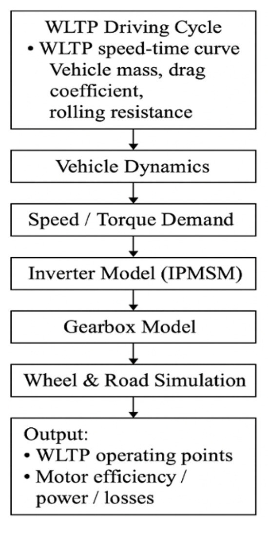
Figure A1.
WLTP-based electric vehicle simulation block diagram used for system-level motor performance evaluation.
To ensure the accuracy and reproducibility of the simulation results, the key FEM settings used in ANSYS Maxwell are summarized below:
- Model Type: 2D transient solver with eddy current effects enabled;Rotor Symmetry: 1/8 model for 8-pole motor (45° mechanical sector);Time Step: 1° mechanical step per solution point, resulting in 90 steps per electrical cycle.
- Mesh Settings:Maximum element size: 0.5 mm in critical regions (airgap, magnets, conductors);Adaptive mesh refinement with a 2% convergence criterion.
- Boundary Conditions:Magnetic vector potential boundary applied on outer stator boundary;Symmetry boundaries on sector sides.
- Solver Accuracy:Relative residual tolerance: 1 × 10⁻⁵;Current excitation applied via coil terminal inputs (winding loss evaluation enabled).
These parameters reflect the trade-off between simulation fidelity and computational efficiency required for multi-point evaluations such as efficiency maps.
References
- Choi, G.; Jang, G.-H.; Choi, M.; Kang, J.; Kang, Y.G.; Kim, S. Optimal Design of a Surface Permanent Magnet Machine for Electric Power Steering Systems in Electric Vehicle Applications Using a Gaussian Process-Based Approach. Actuators 2024, 13, 13. [Google Scholar] [CrossRef]
- Shi, Z. Torque Analysis and Dynamic Performance Improvement of a PMSM for EVs by Skew Angle Optimization. IEEE Trans. Appl. Supercond. 2019, 29, 1–5. [Google Scholar] [CrossRef]
- Zhang, Y.; Cao, W.P.; Morrow, J. Interior permanent magnet motor parameter and torque ripple analysis for EV traction. In Proceedings of the 2015 IEEE International Conference on Applied Superconductivity and Electromagnetic Devices (ASEMD), Shanghai, China, 20–23 November 2015; pp. 386–387. [Google Scholar]
- Liu, H.-C.; Lee, H.-J.; Seol, H.-S.; Cho, S.; Lee, J.; Oh, Y.J. Optimal Slot Design of IPMSM in Railway with Independently Rotating Wheelsets. IEEE Trans. Magn. 2019, 55, 8200404. [Google Scholar] [CrossRef]
- Steinacker, A.; Bergemann, N.; Braghero, P.; Campanini, F.; Cuminetti, N.; De Buck, J.; Ferraris, M. Hair Pin Motors: Possible Impregnation and Encapsulation Techniques, Materials and Variables to Be Considered. In Proceedings of the 2020 AEIT International Conference of Electrical and Electronic Technologies for Automotive (AEIT AUTOMOTIVE), Turin, Italy, 18–20 November 2020; pp. 1–6. [Google Scholar]
- Reinap, A.; Gabassi, M.; Alaküla, M.; Andersson, M. Assessment of Cooling Integration with Direct Cooled Windings. In Proceedings of the 2018 IEEE International Conference on Electrical Systems for Aircraft, Railway, Ship Propulsion and Road Vehicles & International Transportation Electrification Conference (ESARS-ITEC), Nottingham, UK, 7–9 November 2018; pp. 1–6. [Google Scholar]
- Liu, H.-C.; Cho, S.; Hong, H.-S.; Joo, K.-J.; Ham, S.-H.; Lee, J. Comparative Analysis of Magnetic Slot Wedges Design for Increasing Performance of Railway Traction Motor. J. Electr. Eng. Technol. 2017, 12, 2411–2418. [Google Scholar]
- Khoshoo, B.; Aggarwal, A.; Foster, S. A Review of Segmented Stator and Rotor Designs in AC Electric Machines: Opportunities and Challenges. Eng 2025, 6, 7. [Google Scholar] [CrossRef]
- Lee, G.-H.; You, Y.-M. Efficiency Optimization of the Main Operating Points of an EV Traction Motor. Appl. Sci. 2025, 15, 368. [Google Scholar] [CrossRef]
- Ismaeel, S.M.; Ibrahim, M.N.; Rashad, E.M.; Sergeant, P. Asymmetric Hairpin Winding Design for Losses Reduction with Thermal Analysis for an Electric Vehicle Case Study. Energies 2024, 17, 6494. [Google Scholar] [CrossRef]
- Born, H.C.; Keller, A.; Baumann, M.; Heine, M.; Mertens, A. Manufacturing Process and Design Requirements of Litz Wire with Focus on Efficiency Improvement of Traction Motors. In Proceedings of the 2022 12th International Electric Drives Production Conference (EDPC), Regensburg, Germany, 29–30 November 2022; pp. 1–7. [Google Scholar]
- Zhang, H.; Smith, A.C.; Iacchetti, M.F.; Tuohy, P.M.; Rusu, A.-V.; Harrison, S.M.; Manolopoulos, C.D.; Climente-Alarcon, V. Optimizing Loss Performance in Aluminum Litz Wires for Cryogenic Electrical Machines. IEEE Trans. Energy Convers. 2025; Early Access. [Google Scholar]
- Widmer, J.D.; Martin, R.; Mecrow, B.C. Precompressed and Stranded Aluminum Motor Windings for Traction Motors. IEEE Trans. Ind. Appl. 2016, 52, 2215–2223. [Google Scholar] [CrossRef]
- Selema, A.; Tawfiq, K.B.; Ibrahim, M.N.; Sergeant, P. Winding Loss Suppression in Inverter-Fed Traction Motors via Hybrid Coil Materials and Configurations. Appl. Sci. 2023, 13, 11429. [Google Scholar] [CrossRef]
- Huynh, A.T.; Huang, H.; Jiang, J.; Zou, T.; Gerada, D.; Yang, T.; Gerada, C. Optimization and Comparison of 1 MW-Class PM Motors for Aircraft Propulsion Using Litz Wire and Hairpin Windings. IEEE Trans. Magn. 2025; Early Access. [Google Scholar]
- Lemaitre, D.; Sarrazin, B.; Wanderoild, Y.; Lembeye, Y.; Derbey, A. Efficiency-Oriented Design of Litz Wire for Several kW Power Experimented on 20 kW Prototype. In Proceedings of the PCIM Europe Conference, Nuremberg, Germany, 3–7 May 2021. [Google Scholar]
- Um, D.-Y.; Chae, S.-A.; Park, G.-S. AC-Winding-Resistance Calculation of Toroidal Inductors with Solid-Round-Wire and Litz-Wire Winding Based on Complex Permeability Modeling. Machines 2024, 12, 228. [Google Scholar] [CrossRef]
- Sullivan, C.R. Optimal Choice for Number of Strands in a Litz-Wire Transformer Winding. IEEE Trans. Power Electron. 1999, 14, 283–291. [Google Scholar] [CrossRef]
- Arruti, A.; Aizpuru, I.; Mazuela, M.; Ouyang, Z.; Andersen, M.A.E. Evolution of Classical 1-D-Based Models and Improved Approach for the Characterization of Litz Wire Losses. IEEE Trans. Power Electron. 2024, 39, 16371–16381. [Google Scholar] [CrossRef]
- IEC 60287-1-1:2006; Electric Cables—Calculation of the Current Rating—Part 1-1: Current Rating Equations (100% Load Factor) and Calculation of Losses—General. International Electrotechnical Commission: Geneva, Switzerland, 2006.
- Hwang, M.-H.; Han, J.-H.; Kim, D.-H.; Cha, H.-R. Design and Analysis of Rotor Shapes for IPM Motors in EV Power Traction Platforms. Energies 2018, 11, 2601. [Google Scholar] [CrossRef]
- Liu, H.-C.; Joo, K.-J.; Oh, Y.J.; Lee, H.J.; Seol, H.-S.; Jin, C.-S.J.; Kim, W.-H.; Lee, J. Optimal Design of an Ultra-Premium-Efficiency PMA-Synchronous Reluctance Motor with the Winding Method and Stator Parameters to Reduce Flux Leakage and Minimize Torque Pulsations. IEEE Trans. Magn. 2018, 54, 1–5. [Google Scholar] [CrossRef]
- Liu, H.C.; Park, J.S.; An, I.H. Design, Analysis, and Comparison of Electric Vehicle Drive Motor Rotors Using Injection-Molded Carbon-Fiber-Reinforced Plastics. World Electr. Veh. J. 2024, 15, 283. [Google Scholar] [CrossRef]
- Mahmouditabar, F.; Baker, N.J. Design Optimization of Induction Motors with Different Stator Slot Rotor Bar Combinations Considering Drive Cycle. Energies 2024, 17, 154. [Google Scholar] [CrossRef]
- Muazzam, H.; Ishak, M.K.; Hanif, A.; Bhatti, A.I. Compensating Thermal Derated Torque of IPMSM Centric Electric Vehicles. IEEE Access 2022, 10, 22468–22480. [Google Scholar] [CrossRef]
- Kalt, S.; Brenner, L.; Lienkamp, M. Requirements for Electric Machine Design Based on Operating Points from Real Driving Data in Cities. World Electr. Veh. J. 2019, 10, 60. [Google Scholar] [CrossRef]
- Shao, L.; Huang, J.; Feng, C.; Yu, S.; Yang, Y.; Li, Y. Design and Optimisation of Energy-Efficient PM-Assisted Motors over WLTP Class 2 Driving Cycle. IET Electr. Power Appl. 2023, 17, 287–295. [Google Scholar]
- Niu, S.; Zhao, Q.; Niu, S.; Jian, L. A Comprehensive Investigation of Thermal Risks in Wireless EV Chargers Considering Spatial Misalignment from a Dynamic Perspective. IEEE J. Emerg. Sel. Top. Power Electron. 2023, 5, 1560–1571. [Google Scholar] [CrossRef]
Disclaimer/Publisher’s Note: The statements, opinions and data contained in all publications are solely those of the individual author(s) and contributor(s) and not of MDPI and/or the editor(s). MDPI and/or the editor(s) disclaim responsibility for any injury to people or property resulting from any ideas, methods, instructions or products referred to in the content. |
© 2025 by the authors. Licensee MDPI, Basel, Switzerland. This article is an open access article distributed under the terms and conditions of the Creative Commons Attribution (CC BY) license (https://creativecommons.org/licenses/by/4.0/).
