Article

Disturbance Observer-Based Saturation-Tolerant Prescribed Performance Control for Nonlinear Multi-Agent Systems

by
Shijie Chang
*,
Jiayu Bai
,
Haoxiang Wen
and
Shuokai Wei
School of Automation and Software Engineering, Shanxi University, Taiyuan 030000, China
*
Author to whom correspondence should be addressed.
Electronics 2025, 14(16), 3310; https://doi.org/10.3390/electronics14163310
Submission received: 14 July 2025 / Revised: 7 August 2025 / Accepted: 12 August 2025 / Published: 20 August 2025
(This article belongs to the Section Systems & Control Engineering)

Abstract

This study focuses on the adaptive tracking control issue for nonlinear multi-agent systems (MASs) under the influence of asymmetric input constraints and external disturbances. Firstly, an auxiliary system is proposed, which can ensure flexible prescribed performance under input saturation conditions. Meanwhile, by introducing a transformation function, the distributed errors are freed from initial constraints. Employing the backstepping method, the adaptive technique, and a neural network approximation technology, a finite-time prescribed performance adaptive tracking control algorithm is designed, enabling the tracking errors to stably converge within the prescribed performance bounds. Secondly, a composite disturbance observer is developed to estimate and mitigate the combined disturbances, which include external perturbations and approximation errors from radial basis function neural networks (RBF NNs). It not only achieves effective disturbance compensation but also further suppresses the approximation errors of RBF NNs. Finally, stability analysis using the Lyapunov function demonstrates that all closed-loop signals remain uniformly ultimately bounded (UUB), with adaptive tracking errors converging to a compact region within a finite time. Simulation results and comparative studies confirm the proposed method’s effectiveness and advantages, providing a basis for its practical use in distributed control applications.

1. Introduction

Recently, the challenge of achieving consensus control in MASs has drawn considerable interest from control researchers, owing to its theoretical significance and broad applications in areas such as unmanned aerial vehicle (UAV) formations, cooperative robotics, and related fields [1,2,3]. Consensus control is categorized into leaderless consensus and leader–follower consensus tracking. Leader–follower consensus tracking employs distributed protocols based on neighbor information exchange, enabling followers to accurately and rapidly track the leader’s trajectory to achieve global consistency. This problem was first addressed by Olfati-Saber et al. [4], who established a foundational framework for distributed consensus protocols using graph theory, analyzed the effects of switching topologies and communication delays, and provided a robust theoretical basis for subsequent research. Building on this, ref. [5] further developed a fully distributed edge-event-triggered adaptive control strategy for linear MASs, incorporating state feedback and output feedback protocols to achieve leader–follower consensus. This approach enhances system adaptability to network changes through dynamic topologies, significantly reducing communication and computational resource consumption. However, studies in [4,5] primarily focused on linear system models, whereas practical MASs often exhibit nonlinear or uncertain dynamics, significantly increasing the complexity of controller design. To address this challenge, researchers have developed control strategies for nonlinear MASs, including adaptive sliding mode control [6,7], neural network-based control [8,9], and fuzzy logic system control [10,11]. It is noteworthy that, in practical engineering applications, besides ensuring that MASs achieve consensus control, further enhancing system performance is both highly important and necessary.
System performance is a key metric for evaluating the effectiveness of systems, equipment, or processes in achieving intended goals. To improve system performance, Bechlioulis et al. [12] proposed the prescribed performance control (PPC) method, which employs performance functions to limit tracking errors to designated boundaries, ensuring controllable metrics such as convergence rate and overshoot. This approach offers a solution for nonlinear system control. Building on this, Ren et al. [13] extended PPC to distributed consensus tracking in MASs, developing a distributed PPC framework based on neighbor information exchange. By employing finite-time performance functions, this framework improves the followers’ tracking speed toward the leader’s trajectory, ensuring that errors converge to a small, adjustable residual set within a finite duration. Reference [14] further integrated dynamic surface control (DSC) techniques, proposing a distributed PPC-DSC strategy that significantly reduces computational complexity in nonlinear MASs. It is worth noting that in practical systems, physical constraints and environmental factors may significantly impair system performance. Thus, mitigating these limitations to support PPC systems is a critical research problem.
Actuator input saturation, a prevalent physical constraint in practical control systems, may result in reduced system performance or potential instability. To address this issue, numerous anti-saturation control methods have been proposed. Tarbouriech et al. [15] introduced an anti-saturation control strategy based on smooth approximation of saturation functions, constructing continuously differentiable functions to circumvent their non-differentiable nature, thereby restoring the effectiveness of control signals and providing a critical reference for subsequent research. Building on this, to further tackle the consensus tracking problem in nonlinear MASs with unmeasurable states, complex nonlinear dynamics, and input saturation, Ma et al. [16] introduced an adaptive fuzzy control strategy with flexible fixed-time PPC. This approach uses fuzzy logic systems to estimate unknown nonlinear functions, utilizes state observers to monitor leader signals, and designs a prescribed-time auxiliary system to address input saturation, ensuring that tracking errors converge to a specified small residual set within a fixed duration while demonstrating enhanced robustness and computational efficiency. Yue et al. [17] addressed a class of nonlinear MASs affected by input saturation by incorporating correction signals into performance functions, developing a saturation-tolerant PPC tracking control strategy. This approach ensures predefined convergence performance even under input saturation, effectively mitigating its adverse impact on MAS consensus tracking and playing a critical role in balancing input saturation with prescribed performance constraints. Therefore, designing a distributed control strategy that simultaneously addresses prescribed performance and input saturation constraints is of significant importance for meeting practical engineering requirements. However, in the aforementioned literature, internal disturbances were approximated using fuzzy logic techniques to reduce tracking errors, but these methods failed to completely eliminate the impact of disturbances, underscoring the necessity for further research on disturbance mitigation.
Disturbances, which vary in source and nature, can significantly impair system performance or cause instability. To tackle this, Chen et al. [18] proposed a disturbance observer-based control (DOBC) approach that estimates and mitigates mismatched disturbances, overcoming challenges in global adaptive control for nonlinear systems and establishing a basis for anti-disturbance studies. You et al. [19] applied DOBC to distributed consensus tracking in MASs, designing a distributed disturbance observer for directed communication topologies, significantly enhancing system robustness against external disturbances. To address unmeasurable states and unknown disturbances, ref. [20] combined PPC with DOBC, proposing a fuzzy PPC-DOBC control strategy that leverages error transformation and fuzzy logic to approximate unknown nonlinear dynamics, ensuring tracking errors meet predefined performance constraints. To further improve the approximation of system nonlinearities and uncertainties, ref. [21] proposed a composite hierarchical anti-disturbance control strategy, treating external disturbances and model uncertainties as composite disturbances. This approach uses RBF NNs to approximate system dynamics and disturbance observers to estimate disturbances, achieving higher-precision robust control.
Upon analysis, it was found that the above-mentioned research has not yet systematically integrated prescribed performance control, input saturation, and composite disturbance observers with coordinated design. In practical engineering applications, systems typically face not merely one or two of the aforementioned conditions but multiple factors acting concurrently. Under complex operating conditions and performance requirements, achieving coordinated optimization of system performance, input constraints, and disturbance rejection is challenging. Inspired by this, this paper proposes an adaptive PPC strategy that integrates saturation tolerance and composite disturbance observer capabilities for a category of unknown nonlinear MASs constrained by input saturation. The primary contributions of this work are outlined as follows:
  • Existing PPC schemes for MASs typically require initial tracking errors to lie within predefined constraint boundaries and struggle to maintain system stability under input saturation conditions [22]. This paper proposes a saturation-tolerant prescribed performance control (STPPC) framework, which introduces a shift function to transform initial tracking errors to a fixed origin, eliminating stringent requirements on initial conditions. Furthermore, an auxiliary system is developed to create a feedback link between input saturation and output constraints, effectively compensating for saturation effects in real time. This approach significantly enhances the flexibility of performance boundaries.
  • This paper further proposes a composite disturbance observer aimed at achieving precise anti-disturbance control by analyzing multi-source disturbance characteristics and system performance. Tailored for strict-feedback nonlinear MASs, this observer addresses control challenges under mismatched disturbances. Compared to methods that only consider STPPC [18], the proposed observer leverages RBF NNs to accurately estimate composite disturbances, significantly reducing their adverse impact on system performance.
  • Traditional DSC methods, primarily designed for centralized systems [23]. This paper proposes a distributed DSC framework that effectively mitigates the complexity issue in backstepping control by introducing first-order filters and distributed coordinate transformations. Compared to methods in [5], this framework relies solely on local neighbor information, significantly reducing communication and computational burdens. Furthermore, by integrating PPC and a composite disturbance observer, the proposed approach guarantees swift convergence of tracking errors to a specified small residual set, even under challenging conditions with input saturation and multiple disturbance sources, thereby achieving efficient and robust distributed consensus tracking.

2. Preparatory Segment

2.1. Communication Topology

The communication network of the MASs can be represented using a directed graph DG ( T , S , A ) . T = { 1 , , N } symbolizes the collection of nodes that make up the network’s N followers. S T × T denotes the set of edges, representing the communication links among agents. A = [ a k , j ] R N × N is the directed graph’s weighted adjacency matrix. If ( k , j ) S , then a k , j > 0 ; otherwise, a k , j = 0 . There are no self-loops, i.e., a k , k = 0 .
The diagonal in-degree matrix is defined as D = diag { d 1 , , d N } , where d k = j = 1 N a j , k stands for the weighted in-degree connected to node k. The Laplacian matrix is defined as L = [ l k , j ] = D A . The directed graph DG ( T , S , A ) must satisfy the condition of containing a directed spanning tree, meaning there exists a root node that can reach all remaining nodes through directed paths. The leader connection matrix is defined as M = diag { b 1 , , b N } . If the follower k directly receives the leader’s signal, then b k = 1 ; otherwise, b k = 0 .

2.2. System Description

Consider a MAS consisting of one leader and N followers. The dynamic equation of each follower is expressed as follows:
x ˙ i , j = x i , j + 1 + h i , j ( x ¯ i , j ) + d i , j ( t ) , j = 1 , , n 1 x ˙ i , n = u i + h i , n ( x ¯ i , n ) + d i , n ( t ) , i = 1 , 2 , , N y i = x i , 1
where the j-th state variable belonging to the i-th agent is represented as x i , j R , and the state vector of this agent is defined as x ¯ i , j = [ x i , 1 , , x i , j ] T R j , The internal nonlinear dynamics of the system are described by a smooth function. The smooth function h i , j ( x ¯ i , j ) characterizes the system’s internal nonlinear dynamics, and d i , j ( t ) R represents an externally bounded disturbance. The control input u i is subject to asymmetric saturation constraints:
u i = u i , max , v i > u i , max v i , u i , min v i u i , max u i , min , v i < u i , min
where u i , max u i , min , u i , max > 0 , and u i , min < 0 are upper and lower saturation limits, and v i is the designed control signal.

2.3. Saturation-Tolerant Prescribed Performance Control Objective

The distributed error ζ i , 1 is defined as:
ζ i , 1 = j = 1 N a i , j ( y i ( t ) y j ( t ) ) + b i ( y i ( t ) y 0 ( t ) )
Most PPC methods face two challenges: they require satisfying initial constraints and the system singularity problem caused by input saturation. The STPPC proposed in this paper simultaneously addresses both issues. The control strategy employs two time-varying functions to handle error transformation and performance constraints:
Transformation Function: The transformation function T ( t ) is defined as:
T ( t ) = sin π t 2 T a 2 , 0 t < T a 1 , t T a
where T a > 0 is an adjustable deferred time. T ( t ) is C n + 1 function, with T ( 0 ) = 0 , T ( T a ) = 1 , monotonically increasing on [ 0 , T a ) , and constant on [ T a , ) .
Finite-Time Prescribed Performance Function: The Finite-time prescribed performance function F i ( t ) is:
F i ( t ) = F i , 0 t T b exp 1 T b T b t + F i , 1 , 0 t < T b F i , 1 , t T b
where F i , 0 , F i , 1 > 0 are design parameters, and T b is the setting time. F i ( t ) is C n + 1 function, when t > 0 bounded, monotonically decreasing on [ 0 , T b ) , and constant on [ T b , ) .
To remove the initial restrictive condition, an error variable is constructed as follows:
η i , 1 = T ( t ) ζ i , 1
The constrained error variable ζ i , 1 is then transformed into an equivalent unconstrained variable s i , 1 using a modified barrier function (BF) that has the following expression:
s i , 1 = P i , l P i , u ζ i , 1 ( P i , l + η i , 1 ) ( P i , u η i , 1 )
where P i , l and P i , u are η i , 1 ’s lower and upper bounds. The design process of P i , l and P i , u is as follows:
P i , l = F i ( t ) + L i , 1 , P i , u = F i ( t ) + U i , 1
where L i , 1 and U i , 1 are adaptive boundaries.
Input saturation is compensated for by an auxiliary system:
L ˙ i , j = b i , j , l L i , j + L i , j + 1 , L i , j ( 0 ) = 0 L ˙ i , n + 1 = 3 2 + 1 2 sign ( v i u i ) | v i u i | U ˙ i , j = b i , j , u U i , j + U i , j + 1 , U i , j ( 0 ) = 0 U ˙ i , n + 1 = 3 2 1 2 sign ( v i u i ) | v i u i |
where i = 1 , , N , j = 1 , , n and b i , j , l , b i , j , u > 0 are design parameters.
Remark 1.
In addition to input saturation, factors such as dead time, input quantization and time delay will also have negative impacts on the control performance of the system. The constructed auxiliary system (9) can effectively deal with these adverse factors while ensuring the preset performance constraints by establishing the relationship between the system input and output, which can bring direct benefits to the practical application of engineering and the development of control theory.
Based on the above dynamics, we designed an STPPC strategy with feedforward compensation to satisfy the following objectives.
All signals within the closed-loop system remain bounded, and the distributed error ζ i , 1 approaches a compact area close to the origin within a designated area in finite time:
P i , l ( t ) < ζ i , 1 < P i , u ( t ) , t T a
To achieve the aforementioned objectives, reasonable assumptions and lemmas about the system and communication network are required. The relevant assumptions and lemmas are presented below.
Assumption 1
([24]). The reference signal y 0 ( t ) is sufficiently smooth, and its derivatives y 0 ( k ) ( t ) for k = 0 , 1 , , n are bounded. That is, there exists a constant O 0 > 0 such that:
sup t 0 | y 0 ( k ) ( t ) | O 0 , k = 0 , 1 , , n
Assumption 2
([25]). Suppose that the unknown compound disturbance D i , j and its first derivative D ˙ i , j are bounded, that is | D i , j | < d i , j , m and | D ˙ i , j | < d i , j , n , where d i , j , m and d i , j , n are constants greater than 0.
Assumption 3
([26]). The nonlinear function ϕ i , j ( x ¯ i , j ) is continuous and satisfies a local Lipschitz condition. That is, there exists a constant L ϕ i , j > 0 such that for any x ¯ i , j , x ¯ i , j R j :
| ϕ i , j ( x ¯ i , j ) ϕ i , j ( x ¯ i , j ) | L ϕ i , j x ¯ i , j x ¯ i , j
Furthermore, ϕ i , j is bounded on a compact set Ω x ¯ i , j R j , i.e.:
sup x ¯ i , j Ω x ¯ i , j | ϕ i , j ( x ¯ i , j ) | ϕ i , j , m
where ϕ i , j , m > 0 is a known constant.
Lemma 1
([27]). If the leader is designated as the root node, the directed graph DG ( T , S , A ) includes a directed spanning tree. Consequently, the leader connection matrix M contains at least one nonzero element, and the matrix L + M is invertible.
Lemma 2.
([28]). RBF NNs can be used to approximate an unknown smooth continuous function F ( x ¯ i , j ) on a compact set ϖ:
F ( x ¯ i , j ) = W T Φ ( x ¯ i , j ) + δ ( x ¯ i , j )
where x ¯ i , j ϖ , W T is the optimal weight vector, Φ ( x ¯ i , j ) is the basis function vector, and δ ( x ¯ i , j ) is the approximation error satisfying | δ ( x ¯ i , j ) | ε , and
sup x ¯ i , j Ω | F ( x ¯ i , j ) W T Φ ( x ¯ i , j ) | ε
where ε > 0 is a constant.
Lemma 3
([29]). Young’s inequality states that for vectors a R and b R , the following inequality holds:
a b l m m | a | m + 1 n l n | b | n
where l > 0 , m > 1 , n > 1 , and ( m 1 ) ( n 1 ) = 1 .

3. Main Results

3.1. Composite Disturbance Observer Design

As h i , j ( x ¯ i , j ) represents an unknown smooth function according to Lemma 2, for a specified constant Ξ > 0 , there exists an RBF NN W i , j Φ i , j ( x ¯ i , j ) such that:
h i , j ( x ¯ i , j ) = W i , j Φ i , j ( x ¯ i , j ) + ρ i , j , | ρ i , j | Ξ i , j
Define D i , j = d i , j ( t ) + ρ i , j ; then, the system can be reformulated as:
x ˙ i , j = x i , j + 1 + W i , j Φ i , j ( x ¯ i , j ) + D i , j , j = 1 , , n 1 x ˙ i , n = u i + W i , j Φ i , j ( x ¯ i , j ) + D i , n , i = 1 , 2 , , N y i = x i , 1
To compensate for the composite disturbance D i , j in the system, the composite disturbance observer is developed to estimate the disturbance D i , j as follows:
D ^ i , j = k i , d Q i , j f i , j , j = 1 , , n
f ˙ i , j = k i , d x i , j + 1 + W ^ i , j Φ i , j ( x ¯ i , j ) + D ^ i , j w ˙ i , j , f + L ˙ i , j U ˙ i , j , j = 1 , , n 1
f ˙ i , n = k i , d u i + W ^ i , j Φ i , j ( x ¯ i , j ) + D ^ i , n w ˙ i , n , f + L ˙ i , n U ˙ i , n
where D ^ i , j R is the estimated value of the composite disturbance D i , j ; W ^ i , j R 1 × q is the estimated value of the RBF NN weight matrix W i , j , where q represents the count of neurons in the hidden layer; Q i , j is the nonlinear mapping function mentioned in (21); k i , d > 0 is a design parameter; and f i , j R is an auxiliary intermediate variable.

3.2. Controller Design and Stability Analysis

Based on the coordinate transformations:
Q i , 1 = s i , 1 Q i , j = x i , j w i , j , f + L i , j U i , j , j = 2 , , n
To avoid the computational complexity caused by directly differentiating the virtual controller α i , j 1 , a first-order low-pass filter is designed as follows:
w ˙ i , j , f = w i , j , f τ i + α i , j 1 τ i β i
where τ i is a positive design constant, α i 1 is the virtual controller, and β i = 1 ;
Define the filtering error:
e i , j = w i , j , f α i , j 1
The filtering error dynamics is:
e ˙ i , j = e i , j τ i + l i , j , l i , j = α i , j 1
Step 1: Construct a Lyapunov function:
V i , 1 = 1 2 Q i , 1 2 + 1 2 γ i , 1 θ ˜ i , 1 2 + 1 2 D ˜ i , 1 2 + 1 2 e i , 2 2
where γ i , 1 > 0 is a design parameter, the estimation error of θ 1 is denoted by θ ˜ 1 , and the definition of the unknown parameter θ 1 is given in (36). Similarly, D ˜ i , 1 denotes the estimation error of the unknown parameter D i , 1 , whose definition is provided in (29). Taking the derivative of V i , 1 gives
V ˙ i , 1 = Q i , 1 Q ˙ i , 1 1 γ i , 1 θ ˜ i , 1 θ ^ ˙ i , 1 + D ˜ i , 1 D ˜ ˙ i , 1 + e i , 2 e ˙ i , 2
According to the Formulas (3), (6)–(9) and (21), it follows that
Q ˙ i , 1 = ψ i Δ i Q i , 2 + α i , 1 + e i , 2 + H i , 1 + D i , 1 j = 1 N a i , j y ˙ j b i y ˙ 0 + ψ i , l F ˙ i b i , 1 , l L i , 1 + ψ i , u F ˙ i b i , 1 , u U i , 1 + ψ i , T T ˙
where H i , 1 = W i , j Φ i , j ( x ¯ i , j ) + ψ i , 1 ψ i Δ i ψ i Δ i L i , 2 + ψ i Δ i + ψ i , U ψ i Δ i U i , 2 , H i , j = h i , j , j = 2 , , n , Δ i = d i + b i , where d i = j = 1 N a i , j , and
ψ i = Q i , 1 ζ i , 1 = P i , l P i , u ( ζ i , 1 2 T 2 + P i , l P i , u ) ( P i , l + ζ i , 1 T ) 2 ( P i , u ζ i , 1 T ) 2 ψ i , l = Q i , 1 P i , l = P i , u ζ i , 1 2 T ( P i , l + ζ i , 1 T ) 2 ( P i , u ζ i , 1 T ) ψ i , u = Q i , 1 P i , u = P i , l ζ i , 1 2 T ( P i , l + ζ i , 1 T ) ( P i , u ζ i , 1 T ) 2 ψ i , T = Q i , 1 T = P i , l P i , u ζ i , 1 2 ( P i , l P i , u + 2 ζ i , 1 T ) ( P i , l + ζ i , 1 T ) 2 ( P i , u ζ i , 1 T ) 2
Define the disturbance estimation error as
D ˜ i , j = D i , j D ^ i , j
From the interference observer:
D ˜ ˙ i , j = D ˙ i , j D ^ ˙ i , j = D ˙ i , j k i , d W ˜ i , j Φ i , j ( x ¯ i , j ) + D ˜ i , j
For j = 1 , we have
D ˜ i , 1 D ˜ ˙ i , 1 = D ˜ i , 1 D ˙ i , 1 k i , d W ˜ i , 1 Φ i , 1 ( x ¯ i , 1 ) + D ˜ i , 1
By substituting (27) and (31) in (26), we obtain:
V ˙ i , 1 = Q i , 1 ψ i [ Δ i ( H i , 1 + α i , 1 + Q i , 2 + e i , 2 + D i , 1 ) j = 1 N a i , j y ˙ j b i y ˙ 0 ] + ψ i , l Q i , 1 F ˙ i b i , 1 , l L i , 1 + ψ i , u Q i , 1 F ˙ i b i , 1 , u U i , 1 + ψ i , T T ˙ Q i , 1 + D ˜ i , 1 D ˙ i , 1 k i , d ( W ˜ i , 1 Φ i , 1 ( x ¯ i , 1 ) + D ˜ i , 1 ] + e i , 2 e ˙ i , 2 1 γ i , 1 θ ˜ i , 1 θ ^ ˙ i , 1
Let M i , 1 = ψ i Δ i H i , 1 ψ i j = 1 N a i , j y ˙ j ψ i b i y ˙ 0 + 1 2 Q i , 1 + D ˜ i , 1 Q i , 1 D ˙ i , 1 k i , d W ˜ i , 1 Φ i , 1 ( x ¯ i , 1 ) . Since h i , 1 is an unknown smooth nonlinear function, M i , 1 is also smooth and unknown, and can be approximated by an RBF NN:
M i , 1 = B i , 1 * T ϕ i , 1 ( Ƶ i , 1 ) + δ i , 1 ( Ƶ i , 1 ) , | δ i , 1 ( Ƶ i , 1 ) | ε i , 1
Define the unknown constants:
θ i , k = max ξ i , k B i , k * T 2 , k = 1 , 2 , , n
where ξ i , k ( k = 1 , , n ) denotes the dimension of ϕ i , k ( Ƶ i , k ) , and ϕ i , k ( Ƶ i , k ) is a Gaussian function. From the property of Gaussian functions:
ϕ i , k ( Ƶ i , k ) 2 ξ i , k
where B i , k * T is the Euclidean norm of the optimal weight vector. θ ^ i , k is the estimate of the unknown constant θ i , k , and the estimation error is:
θ ˜ i , k = θ i , k θ ^ i , k
According to Lemmas 2 and 3 and (34), the following inequality holds:
Q i , 1 M i , 1 = Q i , 1 B i , 1 * T ϕ i , 1 ( Ƶ i , 1 ) + δ i , 1 ( Ƶ i , 1 ) 1 2 r i , 1 2 Q i , 1 2 ξ i , 1 B i , 1 * T 2 + r i , 1 2 2 + Q i , 1 2 2 + ε i , 1 2 2 1 2 r i , 1 2 Q i , 1 2 θ i , 1 + Q i , 1 2 2 + r i , 1 2 2 + ε i , 1 2 2
where r i , 1 > 0 is a design parameter. Calculating Q i , 1 Q ˙ i , 1 , we have:
Q i , 1 Q ˙ i , 1 Q i , 1 ψ i Δ i 1 2 r i , 1 2 ψ i Δ i Q i , 1 θ i , 1 + α i , 1 + Q i , 2 + e i , 2 + D i , 1 + ψ i , l Q i , 1 F ˙ i b i , 1 , l L i , 1 + ψ i , u Q i , 1 F ˙ i b i , 1 , u U i , 1 + ψ i , T T ˙ Q i , 1 + r i , 1 2 2 + ε i , 1 2 2
By substituting (38) into (32), we obtain:
V ˙ i , 1 Q i , 1 ψ i Δ i 1 2 r i , 1 2 ψ i Δ i Q i , 1 θ i , 1 + α i , 1 + Q i , 2 + e i , 2 + D i , 1 + ψ i , l Q i , 1 F ˙ i b i , 1 , l L i , 1 + ψ i , u Q i , 1 F ˙ i b i , 1 , u U i , 1 + ψ i , T T ˙ Q i , 1 + r i , 1 2 2 + ε i , 1 2 2 + e i , 2 e ˙ i , 2 1 γ i , 1 θ ˜ i , 1 θ ^ ˙ i , 1 k i , d D ˜ i , 1 2
The virtual controller α i , 1 and the parameter adaptive law θ ^ ˙ i , 1 are designed as follows:
α i , 1 = 1 2 r i , 1 2 ψ i Δ i Q i , 1 θ ^ i , 1 D ^ i , 1 c i , 1 Q i , 1 ψ i , l ψ i Δ i F ˙ i b i , 1 , l L i , 1 ψ i , u ψ i Δ i F ˙ i b i , 1 , u U i , 1 ψ i , T ψ i Δ i T ˙ 3 2 Q i , 1
θ ^ ˙ i , 1 = γ i , 1 1 2 r i , 1 2 Q i , 1 2 σ i , 1 θ ^ i , 1
where c i , 1 > 0 is the control gain, and σ i , 1 > 0 is a design parameter.
Substituting (40) and (41) into (39), we obtain:
V ˙ i , 1 c i , 1 ψ i Δ i Q i , 1 2 + ψ i Δ i Q i , 1 D ˜ i , 1 + Q i , 2 + e i , 2 + e i , 2 e ˙ i , 2 + r i , 1 2 2 + ε i , 1 2 2 + σ i , 1 γ i , 1 θ ˜ i , 1 θ ^ i , 1 3 2 ψ i Δ i Q i , 1 2 k i , d D ˜ i , 1 2
According to Young’s inequality in Lemma 3, we obtain:
ψ i Δ i Q i , 1 e i , 2 1 2 ψ i Δ i Q i , 1 2 + 1 2 ψ i Δ i e i , 2 2 ψ i Δ i Q i , 1 D ˜ i , 1 1 2 ψ i Δ i Q i , 1 2 + 1 2 ψ i Δ i D ˜ i , 1 2 ψ i Δ i Q i , 1 Q i , 2 1 2 ψ i Δ i Q i , 1 2 + 1 2 ψ i Δ i Q i , 2 2 σ i , 1 γ i , 1 θ ˜ i , 1 θ ^ i , 1 σ i , 1 2 γ i , 1 θ ˜ i , 1 2 + σ i , 1 2 γ i , 1 θ i , 1 2
From e ˙ i , 2 = e i , 2 τ i + l i , 2 , where l i , 2 = α i , 1 , if l i , 2 is bounded with the upper bound l i , 2 , m , then:
e i , 2 e ˙ i , 2 1 τ i 1 4 e i , 2 2 + l i , 2 , m 2
By substituting (43) and (44) into (42), we obtain:
V ˙ i , 1 c i , 1 ψ i Δ i Q i , 1 2 1 τ i 1 4 1 2 ψ i Δ i e i , 2 2 σ i , 1 2 γ i , 1 θ ˜ i , 1 2 ( k i , d 1 2 ψ i Δ i ) D ˜ i , 1 2 + 1 2 ψ i Δ i Q i , 2 2 + l i , 2 , m 2 + σ i , 1 2 γ i , 1 θ i , 1 2 + r i , 1 2 2 + ε i , 1 2 2
Let Γ i , 1 = r i , 1 2 2 + ε i , 1 2 2 + σ i , 1 2 γ i , 1 θ i , 1 2 . By selecting the parameters k i , d * , τ i * such that 1 τ i 1 4 + τ i * + ψ i Δ i 2 ( τ i * > 0 ), and k i , d 1 2 ψ i Δ i + k i , d * , we have:
V ˙ i , 1 c i , 1 ψ i Δ i Q i , 1 2 k i , d * D ˜ i , 1 2 σ i , 1 2 γ i , 1 θ ˜ i , 1 2 τ i * e i , 2 2 + 1 2 ψ i Δ i Q i , 2 2 + Γ i , 1 + l i , 2 , m 2
Step j ( 2 j n 1 ) : Construct the Lyapunov function:
V i , j = V i , j 1 + 1 2 Q i , j 2 + 1 2 γ i , j θ ˜ i , j 2 + 1 2 D ˜ i , j 2 + 1 2 e i , j + 1 2
where γ i , j > 0 is a design parameter. Taking the derivative, we have:
V ˙ i , j = V ˙ i , j 1 + Q i , j Q ˙ i , j 1 γ i , j θ ˜ i , j θ ^ ˙ i , j + D ˜ i , j D ˜ ˙ i , j + e i , j + 1 e ˙ i , j + 1
According to Formulas (17) and (21), substituting the filter w i , j + 1 , f = α i , j + e i , j + 1 , by calculating the time derivative of the error variable Q i , j , we obtain:
Q ˙ i , j = Q i , j + 1 + α i , j + e i , j + 1 L i , j + 1 + U i , j + 1 + W i , j Φ i , j ( x ¯ i , j ) + D i , j w ˙ i , j , f + L ˙ i , j U ˙ i , j
According to Equation (30), we have:
D ˜ i , j D ˜ ˙ i , j = D ˜ i , j D ˙ i , j k i , d W ˜ i , j Φ i , j ( x ¯ i , j ) + D ˜ i , j
By substituting (49) and (50) into (48), we obtain:
V ˙ i , j = V ˙ i , j 1 + Q i , j ( Q i , j + 1 + α i , j + e i , j + 1 L i , j + 1 + U i , j + 1 + W i , j Φ i , j ( x ¯ i , j ) + D i , j w ˙ i , j , f + L ˙ i , j U ˙ i , j ) + D ˜ i , j D ˙ i , j k i , d W ˜ i , j Φ i , j ( x ¯ i , j ) + D ˜ i , j 1 γ i , j θ ˜ i , j θ ^ ˙ i , j + e i , j + 1 e ˙ i , j + 1
Let M i , j = W i , j Φ i , j ( x i , j ) w ˙ i , j , f + L ˙ i , j U ˙ i , j L i , j + 1 + U i , j + 1 + Q i , j 2 + D ˜ i , j Q i , j D ˙ i , j
k i , d W ˜ i , j Φ i , j ( x ¯ i , j ) . Using the neural network (33), we have:
M i , j = B i , j * T ϕ i , j ( Ƶ i , j ) + δ i , j ( Ƶ i , j ) , | δ i , j ( Ƶ i , j ) | ε i , j
According to Lemma 2 and Formula (52), the following inequality is satisfied:
Q i , j M i , j = Q i , j B i , j * T ϕ i , j ( Ƶ i , j ) + δ i , j ( Ƶ i , j ) 1 2 r i , j 2 Q i , j 2 ξ i , j B i , j * T 2 + r i , j 2 2 + Q i , j 2 2 + ε i , j 2 2 1 2 r i , j 2 Q i , j 2 θ i , j + Q i , j 2 2 + r i , j 2 2 + ε i , j 2 2
where r i , j > 0 is a design constant. Calculating Q i , j Q ˙ i , j , we have:
Q i , j Q ˙ i , j Q i , j Q i , j + 1 + α i , j + e i , j + 1 + 1 2 r i , j 2 Q i , j θ i , j + D i , j + r i , j 2 2 + ε i , j 2 2
By substituting (54) into (51), we obtain:
V ˙ i , j V ˙ i , j 1 + Q i , j 1 2 r i , j 2 Q i , j θ i , j + Q i , j + 1 + α i , j + e i , j + 1 + D i , j 1 γ i , j θ ˜ i , j θ ^ ˙ i , j + e i , j + 1 e ˙ i , j + 1 + r i , j 2 2 + ε i , j 2 2 k i , d D ˜ i , j 2
The virtual control law and adaptive law are formulated as follows:
α i , j = 1 2 r i , j 2 Q i , j θ ^ i , j D ^ i , j c i , j Q i , j 3 2 Q i , j
θ ^ ˙ i , j = γ i , j 1 2 r i , j 2 Q i , j 2 σ i , j θ ^ i , j
By substituting (56) and (57) into (55), we obtain:
V ˙ i , j V ˙ i , j 1 c i , j Q i , j 2 + Q i , j ( D ˜ i , j + Q i , j + 1 + e i , j + 1 ) 3 2 Q i , j 2 + e i , j + 1 e ˙ i , j + 1 + σ i , j γ i , j θ ˜ i , j θ ^ i , j + r i , j 2 2 + ε i , j 2 2 k i , d D ˜ i , j 2
According to Yang’s inequality of Lemma 3, we can get
Q i , j Q i , j + 1 1 2 Q i , j 2 + 1 2 Q i , j + 1 2 Q i , j D ˜ i , j 1 2 Q i , j 2 + 1 2 D ˜ i , j 2 Q i , j e i , j + 1 1 2 Q i , j 2 + 1 2 e i , j + 1 2 σ i , j γ i , j θ ˜ i , j θ ^ i , j σ i , j 2 γ i , j θ ˜ i , j 2 + σ i , j 2 γ i , j θ i , j 2
From e ˙ i , j + 1 = e i , j + 1 τ i + l i , j + 1 , where l i , j + 1 = ( α i , j ) , if l i , j + 1 is bounded and its upper bound is denoted as l i , j + 1 , m , then
e i , j + 1 e ˙ i , j + 1 1 τ i 1 4 e i , j + 1 2 + l i , j + 1 , m 2
Let Γ i , j = 1 2 r i , j 2 + 1 2 ε i , j 2 + σ i , j 2 γ i , j θ i , j 2 , and require that 1 τ i 3 4 + τ i * with τ i * > 0 , k i , d 1 2 + k i , d * ; we have:
V ˙ i , j c i , 1 ψ i Δ i ( t ) Q i , 1 2 + 1 2 ψ i Δ i ( t ) Q i , 2 2 + k = 1 j k i , d * D ˜ i , k 2 σ i , k 2 γ i , k θ ˜ i , k 2 + k = 2 j c i , k Q i , k 2 + 1 2 Q i , k + 1 2 + k = 1 j Γ i , k + k = 2 j + 1 ( l i , k , m 2 τ i * e i , k 2 )
Stepn: Construct the n-th step Lyapunov function:
V i , n = V i , n 1 + 1 2 Q i , n 2 + 1 2 γ i , n θ ˜ i , n 2 + 1 2 D ˜ i , n 2
where γ i , n > 0 is a design parameter. Taking the derivative, we have:
V ˙ i , n = V ˙ i , n 1 + Q i , n Q ˙ i , n 1 γ i , n θ ˜ i , n θ ^ ˙ i , n + D ˜ i , n D ˜ ˙ i , n
According to Formulas (17) and (21), we have:
Q ˙ i , n = u i + W i , j Φ i , j ( x i , j ) + D i , n w ˙ i , n , f + L ˙ i , n U ˙ i , n
According to Formula (30), for j = n , we have:
D ˜ i , n D ˜ ˙ i , n = D ˜ i , n D ˙ i , n k i , d W ˜ i , n Φ i , n ( x ¯ i , n ) + D ˜ i , n
By substituting (64) and (65) into (63) V ˙ i , n , we obtain:
V ˙ i , n V ˙ i , n 1 + Q i , n u i + W i , j Φ i , j ( x i , j ) + D i , n w ˙ i , n , f + L ˙ i , n U ˙ i , n 1 γ i , n θ ˜ i , n θ ^ ˙ i , n + D ˜ i , n D ˙ i , n k i , d W ˜ i , n Φ i , n ( x ¯ i , n ) + D ˜ i , n
Let M i , n = W i , j Φ i , j ( x i , j ) w ˙ i , n , f + L ˙ i , n U ˙ i , n + 1 2 Q i , n + D ˜ i , j Q i , j D ˙ i , n k i , d W ˜ i , n Φ i , n ( x ¯ i , n ) . Using the neural network (33), we have:
M i , n = B i , n * T ϕ i , n ( Ƶ i , n ) + δ i , n ( Ƶ i , n ) , | δ i , n ( Ƶ i , n ) | ε i , n
According to Lemmas 2 and 3 and formula (67), the following inequality holds:
Q i , n M i , n = Q i , n B i , n * T ϕ i , n ( Ƶ i , n ) + δ i , n ( Ƶ i , n ) 1 2 r i , n 2 Q i , n 2 ξ i , n B i , n * T 2 + r i , n 2 2 + Q i , n 2 2 + ε i , n 2 2 1 2 r i , n 2 Q i , n 2 θ i , n + Q i , n 2 2 + r i , n 2 2 + ε i , n 2 2
where r i , n > 0 is a design constant. Calculating Q i , j Q ˙ i , j , we have:
Q i , n Q ˙ i , n Q i , n u i + 1 2 r i , n 2 Q i , n θ i , n 2 + D i , n + r i , n 2 2 + ε i , n 2 2
By substituting (69) into (66), we obtain:
V ˙ i , n V ˙ i , n 1 + Q i , n u i + 1 2 r i , n 2 Q i , n θ i , n + D i , n 1 γ i , n θ ˜ i , n θ ^ ˙ i , n + r i , n 2 2 + ε i , n 2 2 k i , d D ˜ i , n 2
Formulate the control law and adaptive law as follows:
u i = 1 2 r i , n 2 Q i , n θ ^ i , n D ^ i , n c i , n Q i , n 1 2 Q i , n
θ ^ ˙ i , n = γ i , n 1 2 r i , n 2 Q i , n 2 σ i , n θ ^ i , n
By substituting (71) and (72) into (70), we have:
V ˙ i , n V ˙ i , n 1 c i , n Q i , n 2 + Q i , n D ˜ i , n + σ i , n γ i , n θ ˜ i , n θ ^ i , n + r i , n 2 2 + ε i , n 2 2 1 2 Q i , n 2 k i , d D ˜ i , n 2
Apply Young’s inequality to the remaining terms in V ˙ i , n :
Q i , n D ˜ i , n 1 2 Q i , n 2 + 1 2 D ˜ i , n 2 σ i , n γ i , n θ ˜ i , n θ ^ i , n σ i , n 2 γ i , n θ ˜ i , n 2 + σ i , n 2 γ i , n θ i , n 2
By substituting (74) into (73), we have:
V ˙ i , n V ˙ i , n 1 c i , n Q i , n 2 k i , d 1 2 D ˜ i , n 2 σ i , n 2 γ i , n θ ˜ i , n 2 + Γ i , n
where Γ i , n = r i , n 2 2 + ε i , n 2 2 + σ i , n 2 γ i , n θ i , n 2 , select the parameter k i , d 1 2 + k i , d * . Expanding V ˙ i , n 1 , the Lyapunov derivative is obtained as:
V ˙ i , n c i , 1 ψ i Δ i Q i , 1 2 + 1 2 ψ i Δ i Q i , 2 2 + k = 1 n k i , d * D ˜ i , k 2 σ i , k 2 γ i , k θ ˜ i , k 2 + k = 2 n ( c i , k Q i , k 2 + l i , k , m 2 τ i * e i , k 2 + k = 1 n Γ i , k + k = 2 n 1 1 2 Q i , k + 1 2
Remark 2.
In the design process of the traditional Backstepping method, it is necessary to repeatedly calculate α ˙ i . Due to the high complexity of nonlinear systems and the fact that α i contains many nonlinear variables, the computational load and complexity of the corresponding controller design are quite high. In the above mentioned design process, the DSC method is combined with RBF NN approximation and adaptive techniques, which effectively alleviates the "complexity explosion" problem in traditional design. By introducing a first-order low-pass filter (22), the repeated differentiation of the virtual controller is avoided, and the computational complexity is reduced from O ( n 2 ) to O ( n ) , where n is the system order. The RBF NN (16) introduces computational load due to the online weight adaptation, but this can be effectively controlled through optimized design. By using a small number of neurons and precalculating the Gaussian basis functions, the real time computation is simplified into efficient matrix operations, which simplifies the design process of the Backstepping method.

3.3. Stability Analysis

Theorem 1.
Under the conditions of Assumptions 1–3 and Lemmas 1–3, for the nonlinear multi-agent system (1), by designing the composite disturbance observer (18), the auxiliary system (9), the virtual and actual controllers (40), (56), and (71), and the adaptive update laws (41), (57), and (72), the following can be achieved:
  • The system achieves semi-global stability, and all signals are ultimately bounded;
  • The distributed error ζ i , 1 can converge to the preassigned region ( P i , l , P i , u ) before the given time T a .
Proof. 
Define the global Lyapunov function as
V = i = 1 N V i , n
The derivative of this is
V ˙ = i = 1 N V ˙ i , n i = 1 N [ c i , 1 ψ i Δ i Q i , 1 2 + 1 2 ψ i Δ i Q i , 2 2 + k = 1 n k i , d * D ˜ i , k 2 σ i , k 2 γ i , k θ ˜ i , k 2 + k = 2 n c i , k Q i , k 2 + l i , k , m 2 τ i * e i , k 2 + k = 1 n Γ i , k + k = 2 n 1 1 2 Q i , k + 1 2 ] K V + Λ
where K = min 2 c i , 1 ψ i Δ i , 2 c i , 2 ψ i Δ i , 2 c i , k 1 , 2 k i , d * , σ i , k , 2 τ i * , Λ = i = 1 N k = 1 n Γ i , k + i = 1 N
k = 2 n l i , k , m 2 .
By multiplying by e a t and calculating the integral, one can finally achieve:
V V Λ K e a t + Λ K V + Λ K
If V = p and K > Λ p , then V ˙ 0 . This implies that V p is an invariant set. Thereby, all signals of the closed-loop NMAS are SGUUB.
The stability analysis confirms that the proposed control strategy guarantees semi-global practical (SPFS) finite-time stability, fast convergence of disturbance estimation, and PPC for distributed tracking error under input saturation, unknown nonlinearities, and external disturbances, thus providing a theoretical foundation for subsequent simulation validation. □

4. Simulations

In this section, the effectiveness of the proposed control strategy is demonstrated through its application to the inverted pendulum system. The leader is denoted as 0, while the followers are labeled as 1, 2, and 3. The information interaction between the leader and the followers is described by the communication topology in Figure 1. Subsequently, the dynamic model of the followers is described as
ω ˙ i = Ω i J i Ω ˙ i = u i m i g i l i sin ( ω i ) τ i Ω i
where ω i and Ω i represent the angle and angular velocity of the inverted pendulum, respectively. m i and l i are the mass and length of the pendulum, respectively. J i denotes the moment of inertia. τ i is the coefficient of friction, and g i is the acceleration due to gravity. The reference signal of the leader is set as ω i ( t ) = 1.5 sin ( 0.5 t ) .
In the simulation of this paper, the system parameters and control parameters are selected as follows: x 1 ( 0 ) = [ 0.9 , 0.1 ] T , x 2 ( 0 ) = [ 0.8 , 0.1 ] T , x 3 ( 0 ) = [ 0.95 , 0.05 ] T , F i , 0 = 5.0 , F i , = 0.05 , a F = 5.0 , T t = 5.0 , b L , i j = b U , i j = [ 0.5 , 0.5 ] T , k i , d = [ 30 , 50 ] T , τ = 0.002 , β = 0.5 , c i j = [ 52 , 58 ] T , γ i j = [ 13 , 17 ] T , and σ i j = [ 13 , 24 ] T .
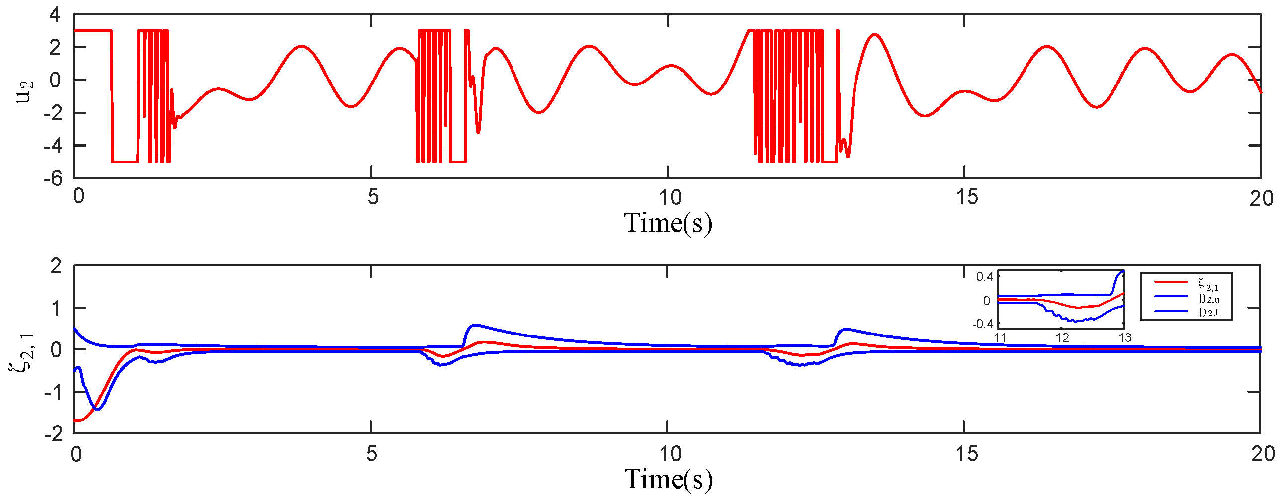
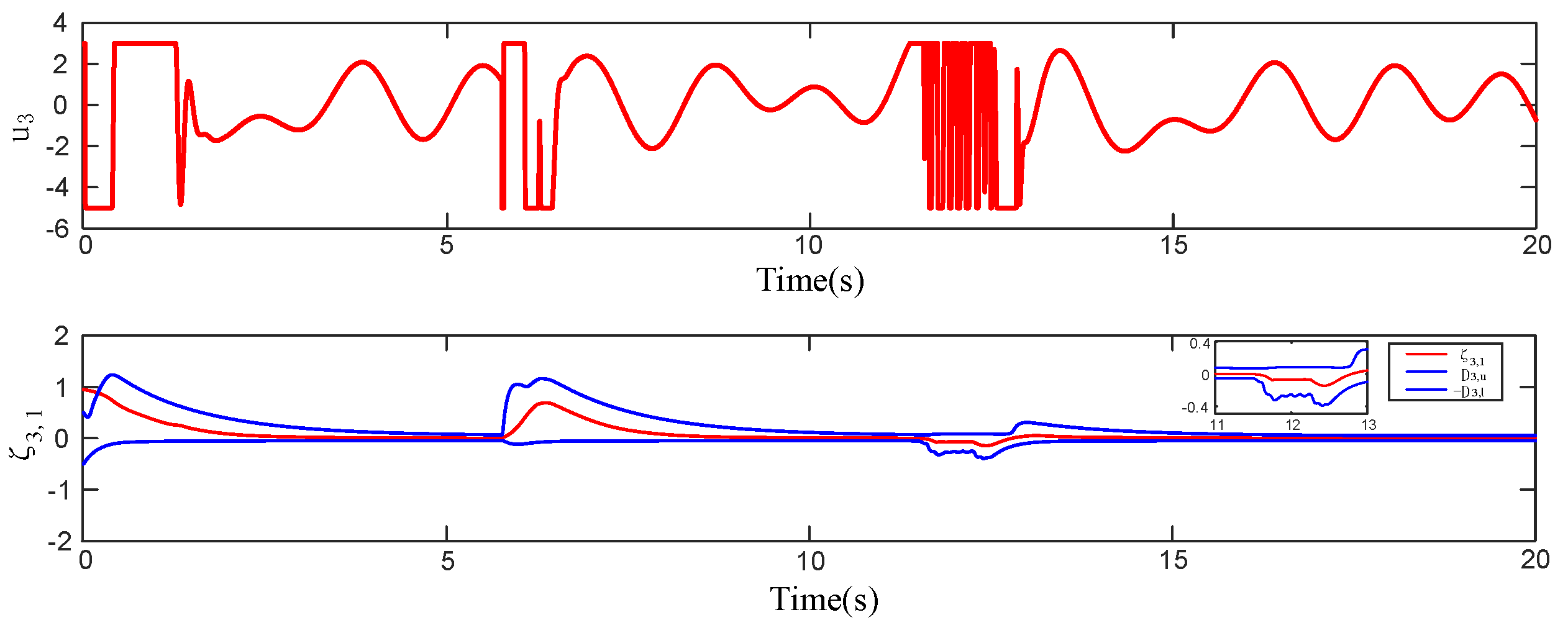
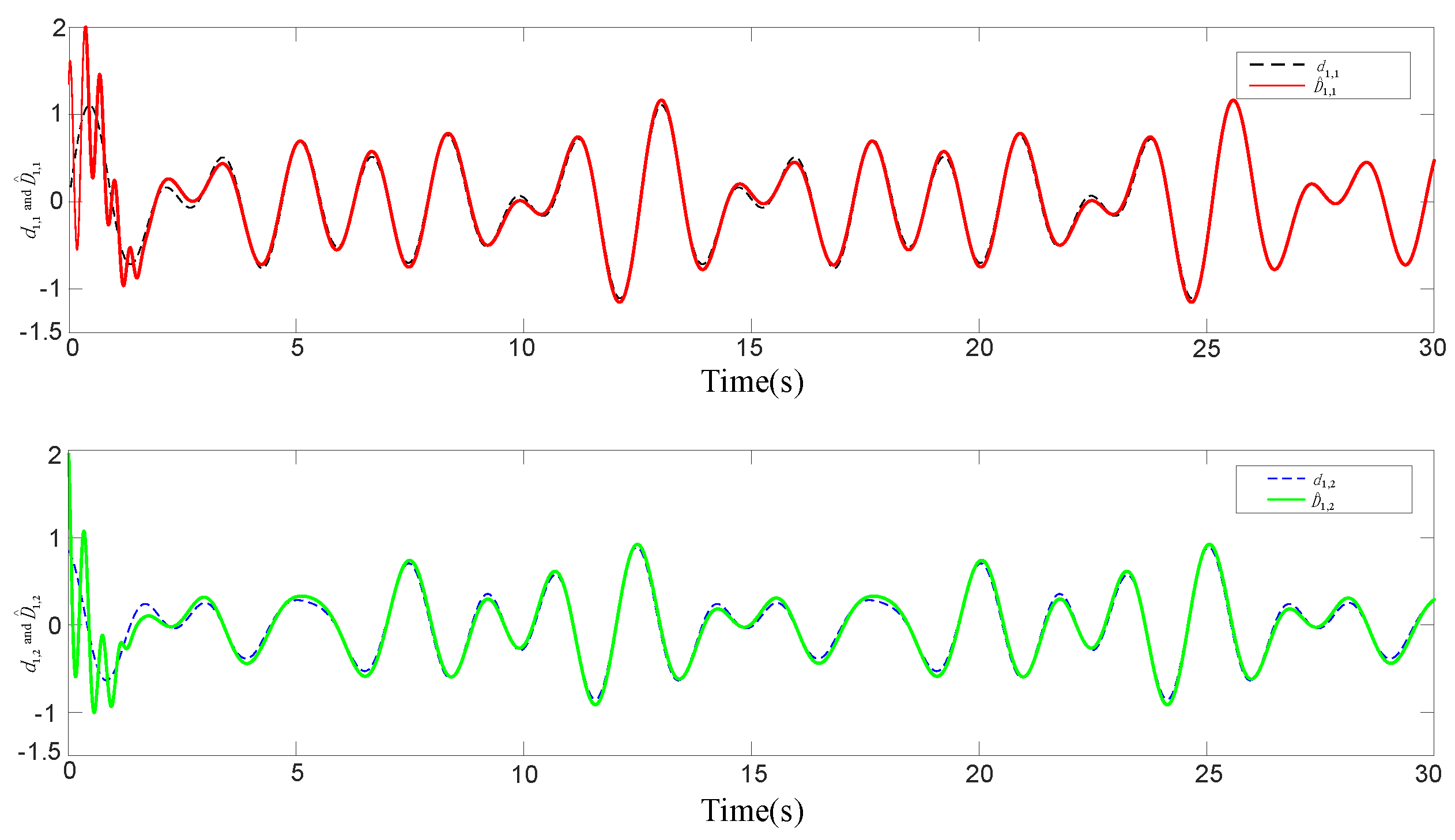
Figure 2 shows the output tracking curves of the leader and the follower. Figure 3, Figure 4 and Figure 5, respectively, present the distributed error ζ i , its performance boundary, and the variation in the control input for each agent ( i = 1 , 2 , 3 ). The simulation results indicate that the control strategy proposed in this paper can ensure that the distributed error enters the preset performance boundary before T a = 0.56 s and remains within the boundary thereafter. Meanwhile, the distributed error converges before T b = 3 s and stays within a stable range. It can be observed from Figure 3 that the control input saturates at t = 7 s and t = 12 s , causing a significant fluctuation in the error. However, the control strategy proposed in this paper can effectively deal with input saturation by flexibly adjusting the preset performance boundary, thereby guaranteeing the system’s stable performance. The results in Figure 4 and Figure 5 further verify this conclusion. Compared with the control method proposed in [30], the results are shown in Figure 6. When input saturation occurs, the method in [30] cannot dynamically adjust the performance boundary, leading to violent error fluctuations and causing singularity problems, which prevent the system from operating normally. In contrast, the method proposed in this paper demonstrates stronger robustness and adaptability. Figure 7 shows the comparison curves of the actual disturbance and the estimated disturbance, indicating that the proposed disturbance observer can efficiently and accurately estimate the unknown composite disturbance. Figure 8 presents the state curves of the auxiliary system for each agent, showing that all states remain bounded, which verifies the stability and reliability of the control strategy.

5. Conclusions

This paper proposes a distributed control framework for addressing the consensus tracking problem in nonlinear MASs under input saturation, complex nonlinear dynamics, and external disturbances. To overcome the limitations of existing PPC schemes, which require initial tracking errors to lie within predefined constraint boundaries and struggle with input saturation [23], the proposed STPPC framework introduces a shift function and an auxiliary system to eliminate stringent initial condition requirements and compensate for input saturation effects in real time, significantly enhancing the flexibility of performance bounds and ensuring rapid convergence of tracking errors to a predefined small residual set. Furthermore, to address the challenge of multi-source mismatched disturbances, a composite disturbance observer is designed, leveraging RBF NNs to accurately estimate composite disturbances, and integrating PPC, fault-tolerant control (FTC), DSC, and DOBC to achieve finite-time convergence of the closed-loop system and effective disturbance suppression [15]. Additionally, by extending the traditional DSC method to a distributed framework with first-order filters and distributed coordinate transformations, this paper effectively mitigates the “complexity explosion” issue inherent in backstepping control, relying solely on local neighbor information to achieve efficient consensus tracking, making it particularly suitable for resource-constrained scenarios such as sensor networks [10,21]. These contributions provide a robust, efficient, and practical solution for distributed consensus control in nonlinear MASs.

Author Contributions

Conceptualization, S.C.; methodology, S.C.; software, H.W.; validation, S.C.; resources, J.B.; writing—original draft, S.C.; visualization, J.B.; supervision, H.W. and S.W. All authors have read and agreed to the published version of the manuscript.

Funding

This research received no external funding.

Data Availability Statement

The original contributions presented in this study are included in the article. Further inquiries can be directed to the corresponding author.

Conflicts of Interest

The authors declare no conflicts of interest.

References

  1. Xiao, W. B.; Cao, L.; Li, H. Y.; Lu, R. Q. Observer-based adaptive consensus control for nonlinear multi-agent systems with time-delay. Sci. China Inf. Sci. 2020, 63, 132202:1–132202:17. [Google Scholar] [CrossRef]
  2. Zhang, H.; Ren, H.; Mu, Y.; Han, J. Optimal Consensus Control Design for Multiagent Systems with Multiple Time Delay Using Adaptive Dynamic Programming. IEEE Trans. Cybern. 2022, 52, 12832–12842. [Google Scholar] [CrossRef] [PubMed]
  3. Liang, H.; Chen, L.; Pan, Y.; Lam, H. -K. Fuzzy-Based Robust Precision Consensus Tracking for Uncertain Networked Systems With Cooperative–Antagonistic Interactions. IEEE Trans. Fuzzy Syst. 2023, 31, 1362–1376. [Google Scholar] [CrossRef]
  4. Olfati-Saber, R.; Murray, R.M. Consensus problems in networks of agents with switching topology and time-delays. IEEE Trans. Autom. Control 2004, 49, 1520–1533. [Google Scholar] [CrossRef]
  5. Zhang, H.; Zhang, J.; Cai, Y.; Sun, S.; Sun, J. Leader-following consensus for a class of nonlinear multiagent systems under event-triggered and edge-event triggered mechanisms. IEEE Trans. Cybern. 2022, 52, 7643–7654. [Google Scholar] [CrossRef]
  6. Li, Z.; Liu, X.; Ren, W.; Xie, L. Distributed consensus of linear multi-agent systems with adaptive dynamic protocols. Automatica 2013, 49, 1986–1995. [Google Scholar] [CrossRef]
  7. Yao, D.; Li, H.; Shi, Y. Adaptive Event-Triggered Sliding-Mode Control for Consensus Tracking of Nonlinear Multiagent Systems With Unknown Perturbations. IEEE Trans. Cybern. 2023, 53, 2672–2684. [Google Scholar] [CrossRef]
  8. Lian, Y.; Xia, J.; Park, J.H.; Sun, W.; Shen, H. Disturbance Observer-Based Adaptive Neural Network Output Feedback Control for Uncertain Nonlinear Systems. IEEE Trans. Neural. Netw. Learn. Syst. 2023, 34, 7260–7270. [Google Scholar] [CrossRef]
  9. Li, H.J.; Zhang, J.J.; Jing, L.; Wang, Y. Neural-network-based adaptive quasi-consensus of nonlinear multi-agent systems with communication constrains and switching topologies. Nonlinear Anal. Hybrid Syst. 2020, 35, 100833. [Google Scholar] [CrossRef]
  10. Chen, J.; Li, J.; Yuan, X. Global Fuzzy Adaptive Consensus Control of Unknown Nonlinear Multiagent Systems. IEEE Trans. Fuzzy Syst. 2020, 28, 510–522. [Google Scholar] [CrossRef]
  11. Deng, X.; Zhang, X. Adaptive Fuzzy Tracking Control of Uncertain Nonlinear Multi-Agent Systems with Unknown Control Directions and a Dead-Zone Fault. Mathematics 2022, 10, 2655. [Google Scholar] [CrossRef]
  12. Bechlioulis, C.P.; Rovithakis, G.A. Robust adaptive control of feedback linearizable MIMO nonlinear systems with prescribed performance. IEEE Trans. Autom. Control 2008, 53, 2090–2099. [Google Scholar] [CrossRef]
  13. Cui, G.; Xu, S.; Ma, Q.; Li, Y.; Zhang, Z. Prescribed performance distributed consensus control for nonlinear multi-agent systems with unknown dead-zone input. Int. J. Control 2017, 91, 1053–1065. [Google Scholar] [CrossRef]
  14. Chen, G.; Zhao, Y. Distributed adaptive output-feedback tracking control of non-affine multi-agent systems with prescribed performance. J. Frankl. Inst. 2018, 355, 6087–6110. [Google Scholar] [CrossRef]
  15. Tarbouriech, S.; Garcia, G.; Gomes da Silva, J.M., Jr.; Queinnec, I. Stability and Stabilization of Linear Systems with Saturating Actuators; Springer: Berlin/Heidelberg, Germany, 2011. [Google Scholar] [CrossRef]
  16. Ma, C.; Dong, D. Non-singular practical fixed-time prescribed performance adaptive fuzzy consensus control for multi-agent systems based on an observer. IEEE/CAA J. Autom. Sin. 2025, 12, 1209–1220. [Google Scholar] [CrossRef]
  17. Yue, X.; Zhang, H.; Sun, J.; Wan, L. Adaptive event-triggered saturation-tolerant control for multiagent systems based on finite-time fuzzy learning. IEEE Trans. Fuzzy Syst. 2024, 32, 5638–5647. [Google Scholar] [CrossRef]
  18. Chen, W. H. Nonlinear Disturbance Observer Based Control for Nonlinear Systems with Harmonic Disturbances. IFAC Proc. Vol. 2001, 34, 329–334. [Google Scholar] [CrossRef]
  19. Ai, X. L.; Yu, J. Q.; Jia, Z. Y.; Yang, D.; Xu, X.; Shen, Y. C. Disturbance observer–based consensus tracking for nonlinear multiagent systems with switching topologies. Int. J. Robust Nonlinear Control 2018, 28, 2144–2160. [Google Scholar] [CrossRef]
  20. Liu, W.; Zhao, J.; Zhao, H.; Ma, Q.; Xu, S.; Park, J. H. Composite-Disturbances-Observer-Based Finite-Time Fuzzy Adaptive Dynamic Surface Control of Nonlinear Systems With Preassigned Performance. IEEE Trans. Fuzzy Syst. 2023, 31, 3710–3720. [Google Scholar] [CrossRef]
  21. Yan, X. H.; Liu, Y. G. Global practical tracking by output-feedback for nonlinear systems with unknown growth rate. Sci. China Inf. Sci. 2011, 54, 2079–2090. [Google Scholar] [CrossRef]
  22. Sui, S.; Xu, H.; Tong, S.; Chen, C.L.P. Prescribed performance fuzzy adaptive output feedback control for nonlinear MIMO systems in a finite time. IEEE Trans. Fuzzy Syst. 2022, 30, 3633–3644. [Google Scholar] [CrossRef]
  23. Yang, Z.; Zhao, W.; Kou, J.; Ma, Y.; Sun, Z.; Wang, Y.; Shi, Y. Observer-Based Fuzzy Adaptive Dynamic Surface Force Control for Pneumatic Polishing System End-Effector with Uncertain Contact Environment Model. IEEE Trans. Autom. Sci. Eng. 2025, 22, 17898–17913. [Google Scholar] [CrossRef]
  24. Xing, L. T.; Wen, C. Y.; Su, H. Y.; Liu, Z. T.; Cai, J. P. Robust control for a class of uncertain nonlinear systems with input quantization. Int. J. Robust Nonlinear Control 2016, 26, 1585–1596. [Google Scholar] [CrossRef]
  25. Zinage, V.; Chandra, R.; Bakolas, E. Disturbance Observer-Based Robust Integral Control Barrier Functions for Nonlinear Systems with High Relative Degree. In Proceedings of the 2024 American Control Conference (ACC), Toronto, ON, Canada, 10–12 July 2024; pp. 2470–2475. [Google Scholar] [CrossRef]
  26. Zemouche, A.; Boutayeb, M. On LMI conditions to design observers for Lipschitz nonlinear systems. Automatica 2013, 49, 585–591. [Google Scholar] [CrossRef]
  27. Li, Z.; Wen, G.; Duan, Z.; Ren, W. Designing Fully Distributed Consensus Protocols for Linear Multi-Agent Systems With Directed Graphs. IEEE Trans. Autom. Control 2015, 60, 1152–1157. [Google Scholar] [CrossRef]
  28. Yang, C.; Jiang, Y.; Na, J.; Li, Z.; Cheng, L.; Su, C. -Y. Finite-Time Convergence Adaptive Fuzzy Control for Dual-Arm Robot With Unknown Kinematics and Dynamics. IEEE Trans. Fuzzy Syst. 2019, 27, 574–588. [Google Scholar] [CrossRef]
  29. Zhang, Y. H.; Liang, H. J.; Ma, H.; Zhou, Q.; Yu, Z. D. Distributed adaptive consensus tracking control for nonlinear multi-agent systems with state constraints. Appl. Math. Comput. 2018, 326, 16–32. [Google Scholar] [CrossRef]
  30. Kang, S.; Liu, P.X.; Wang, H. Adaptive fuzzy finite-time prescribed performance control for uncertain nonlinear systems with actuator saturation and unmodeled dynamics. Asian J. Control 2024, 26, 1881–1891. [Google Scholar] [CrossRef]
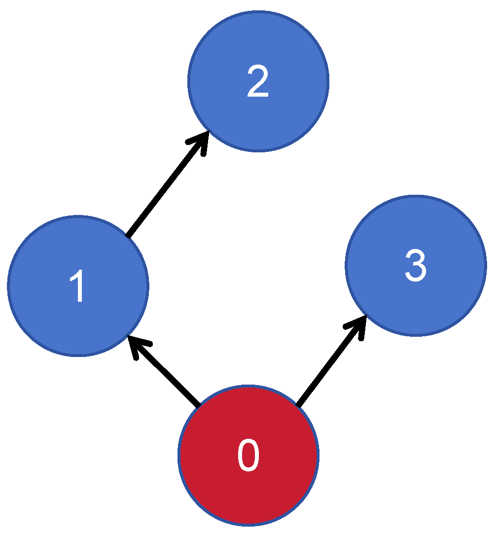
Figure 1. Communication topology.
Electronics 14 03310 g001
Figure 2. Tracking performance.
Electronics 14 03310 g002
Figure 3. The control input and the distributed error of follower 1 under STPPC.
Electronics 14 03310 g003
Figure 4. The control input and the distributed error of follower 2 under STPPC.
Electronics 14 03310 g004
Figure 5. The control input and the distributed error of follower 3 under STPPC.
Electronics 14 03310 g005
Figure 6. Input saturation occurring in the adaptive backstepping fault-tolerant control based on practical prescribed-time stability.
Electronics 14 03310 g006
Figure 7. The NDO for d 1 and d 2 .
Electronics 14 03310 g007
Figure 8. Auxiliary system states.
Electronics 14 03310 g008
Disclaimer/Publisher’s Note: The statements, opinions and data contained in all publications are solely those of the individual author(s) and contributor(s) and not of MDPI and/or the editor(s). MDPI and/or the editor(s) disclaim responsibility for any injury to people or property resulting from any ideas, methods, instructions or products referred to in the content.