Article

Multi-Objective Optimization Design of Bearingless Interior Permanent Magnet Synchronous Motor Based on MOWOA

1
School of Electrical and Information Engineering, Jiangsu University, Zhenjiang 212013, China
2
School of Mechanical Engineering, Jiangsu University, Zhenjiang 212013, China
*
Author to whom correspondence should be addressed.
Electronics 2025, 14(15), 3080; https://doi.org/10.3390/electronics14153080
Submission received: 2 July 2025 / Revised: 28 July 2025 / Accepted: 30 July 2025 / Published: 31 July 2025

Abstract

Bearingless interior permanent magnet synchronous motors (BIPMSMs) have received considerable attention in recent research due to their advantages of high speed, high power density, and absence of mechanical wear. In order to improve the torque and suspension performance of the BIPMSM, an optimization design method of BIPMSM is proposed in this paper based on sensitivity analysis, response surface fitting, and the multi-objective whale optimization algorithm (MOWOA). Firstly, the structure and operation principle of the BIPMSM are introduced. Secondly, significant variables are extracted based on sensitivity analysis. Then, regression equations of the significant variables and optimization objectives are fitted by the response surface method, and global optimization is performed with MOWOA. Finally, the motor performance before and after optimization is compared. The results demonstrate that the proposed multi-objective optimization design scheme can significantly improve the performance of the BIPMSM and effectively shorten the design cycle.

1. Introduction

Permanent magnet synchronous motors (PMSMs) are widely used in high-end equipment, such as rail transportation, CNC machine tools, aircraft, robots, and agricultural machinery automation [1,2,3], due to their high efficiency, high power density, and high reliability [4,5,6,
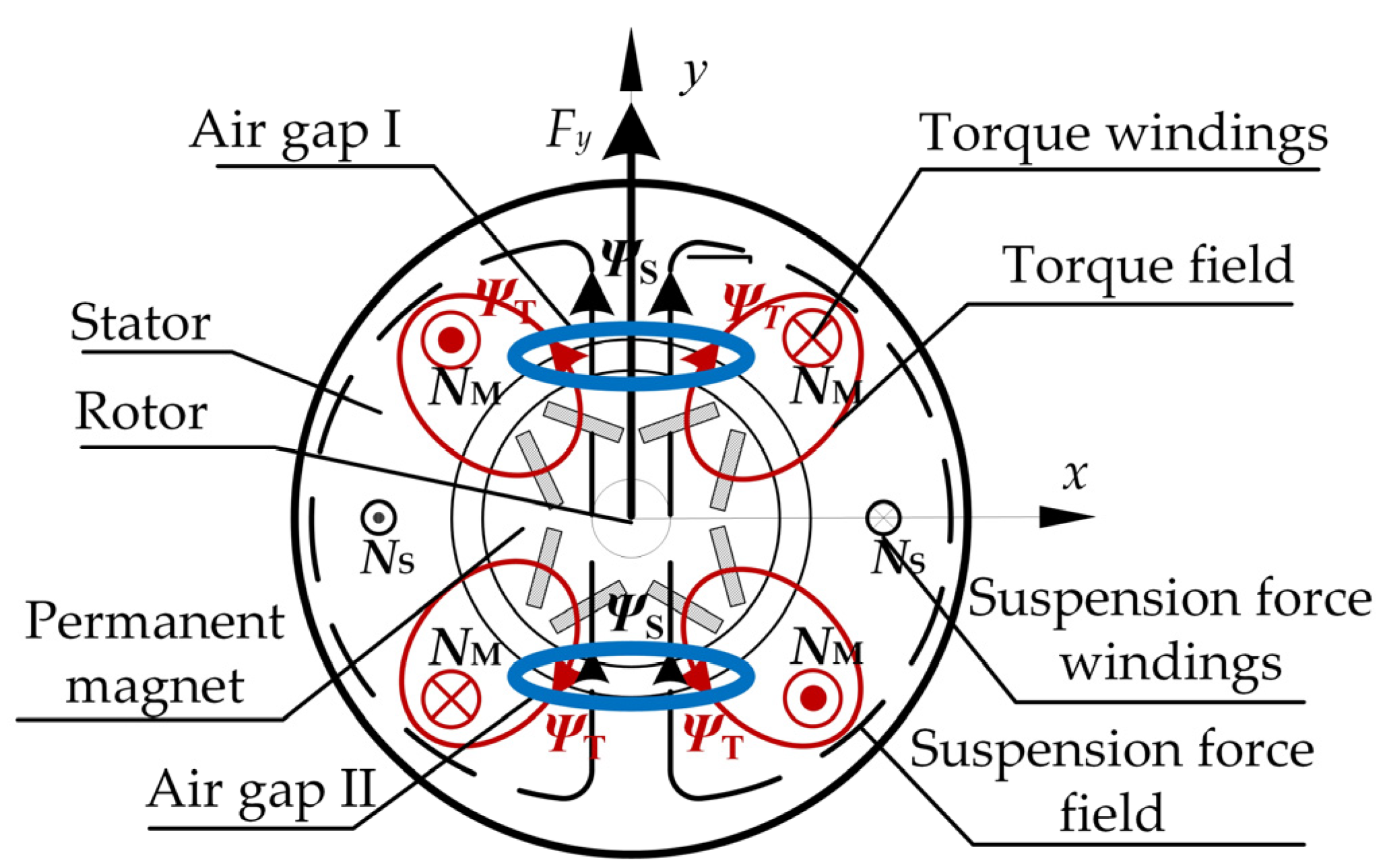
7]. Compared with the PMSM, the interior permanent magnet synchronous motor (IPMSM) has the advantages of better demagnetization resistance, high power density, and a wide speed regulation range. The bearingless interior permanent magnet synchronous motor (BIPMSM) combines the IPMSM and magnetic suspension technology, which is a breakthrough and innovation in electromechanical drive systems. The torque windings and suspension force windings are embedded in the stator of the BIPMSM. By designing these windings with the pole pair numbers differing by 1, the suspension force control can be realized by changing the suspension force windings current. By incorporating magnetic suspension technology, the BIPMSM not only retains the advantages of the IPMSM but also achieves the advantages of no friction, no mechanical wear, low noise, and long service life, which meets the requirements of clean, corrosion-resistant, and high-speed operating environments, leading to widespread applications in aerospace, biomedicine, chemical processing, and other high-tech sectors [8,9].
Especially in the context of flywheel battery system research, the BIPMSM meets the characteristics of high speed, high efficiency, and a wide range of adjustable speeds required by flywheel battery systems. These applications place high demands on the torque performance and suspension force performance of BPMSMs. Therefore, it is crucial to study the relationship between the target performance and motor parameters in the BIPMSM design, such as the distribution and size of the permanent magnets built into the permanent magnet synchronous motor and the design of the motor stator slots. At the same time, these motor parameters are complex and numerous, so they need to be optimized through multi-objective optimization. To identify an optimal solution ensuring stabilization of motor torque and suspension force, parameter design optimization for the BIPMSM increasingly employs intelligent algorithms such as differential evolution, multi-objective particle swarm optimization, and genetic algorithms [10,11,12,13,14,15]. In [16], a pole optimization design method based on unequal amplitude modulation is proposed, with optimization objectives of torque enhancement and suspension performance improvement. According to this method, the optimized unequal amplitude modulation pole structure effectively mitigates the motor’s cogging effect while simultaneously enhancing both torque and suspension performance. In [17], a design method of BPMSM based on electromagnetic computation is proposed. According to this method, the short pitch winding structure and the cosine shape of permanent magnets are used, which can effectively suppress the high harmonics and improve the magnetic field distribution in the BPMSM. In [18], a new permanent magnet rotor structure is proposed. By finite element analysis (FEA), the proposed permanent magnet rotor configuration is demonstrated to significantly improve motor suspension performance. In [19], an innovative single-winding topology for six-phase BPMSM is proposed. FEA was conducted to simulate the proposed motor model, which verified that this method can improve the torque performance and suspension performance of the motor. All the optimization methods in the above literature improve the motor performance to some extent, but they only focus on a single or a small number of optimization variables during the optimization and tend to rely on the finite element analysis results, which leads to an overly cumbersome optimization process. The BIPMSM, on the other hand, has high requirements for both torque and suspension performance, so multi-objective optimization design is introduced into bearingless motors. In [20], an outer rotor coreless BPMSM was designed, with its torque and suspension performance co-optimized through an integrated Taguchi–response surface methodology (T-RSM). In [21], a five-phase BPMSM with 10 slots and 8 poles was proposed, employing an integrated approach of response surface methodology (RSM) and multi-objective optimization to optimize torque and suspension performance. The optimization results demonstrated that this approach could effectively improve both torque output and suspension performance. In [22], a 10 kW, 100k rpm ultra-high-speed BPMSM incorporating auxiliary slots was designed, where multi-objective optimization methods were employed to simultaneously reduce eddy current losses and improve electromagnetic performance of the motor. The above-mentioned multi-objective optimization algorithms in the literature have positive results for the optimization of the target motor. However, most optimization algorithms primarily focus on surface-mounted BPMSMs, with limited research on BIPMSMs. Compared to surface-mounted designs, BIPMSMs offer superior demagnetization resistance and a wider speed regulation range, making them more suitable for high-speed applications. Therefore, this paper employs the multi-objective whale optimization algorithm (MOWOA) to optimize the design of the BIPMSM. MOWOA has better diversity and intergenerational distance characteristics; it has advantages in balancing global search and local optimization, thereby reducing the risk of getting stuck in a local optimum [23].
This paper takes performance indicators such as torque and suspension force of the BIPMSM as optimization targets and the motor stator slot and permanent magnet structure as optimization variables. Sensitivity analysis sifts dominant design parameters, while response surface methodology (RSM) derives relationship equations between optimization objectives and optimization variables. R2, RMSE, and cross-validation methods were used to verify the fit of the regression fitting equation. Finite element simulation of the optimized BIPMSM parameters and pre-/post-optimization performance comparison verified NSWOA’s effectiveness.
The main objective of this paper is to design a multi-objective optimization design scheme for the BIPMSM based on MOWOA. Firstly, the BIPMSM suspension force generation mechanism and motor structure are introduced in Section 2; the FEA verifies the suspension force generation mechanism. The detailed process of optimization is described in 
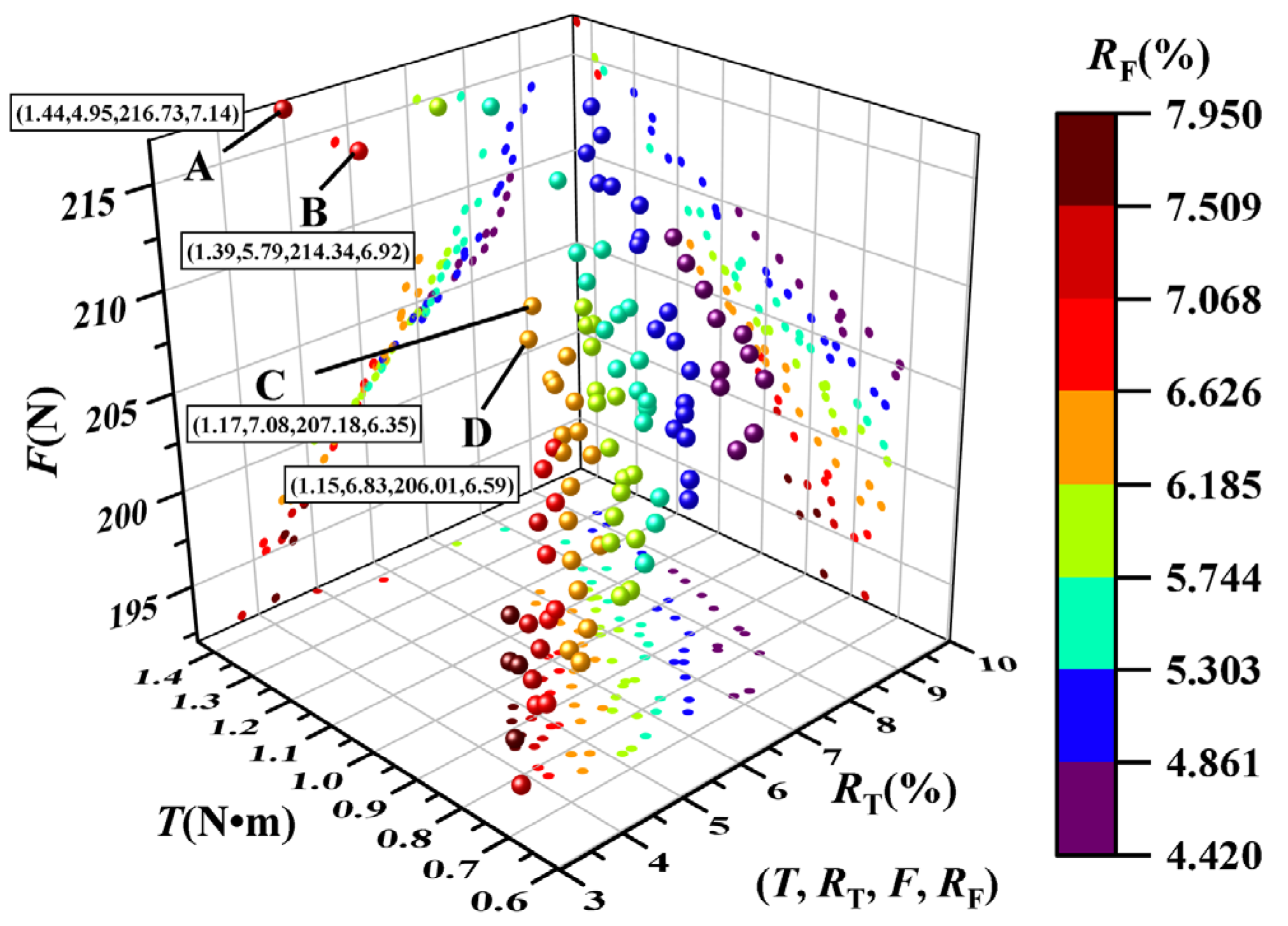
Section 3, including the optimization objectives, determination of optimization variables, sensitivity analysis, response surface method modeling, and generation of Pareto front using MOWOA. Through comparative validation, it can be seen that MOWOA-optimized BIPMSM structural parameters can lead to a combined optimal performance of each objective. Finally, Section 4 summarizes the paper.

2. Principles of Motor Operation and Optimization Algorithms

2.1. Principle of Radial Suspension Force Generation and Simulation Verification

The radial suspension force of the BIPMSM originates from the superposition of the torque magnetic field and the suspension magnetic field, and the stable suspension of the rotor can be realized by adjusting the current of the suspension force winding. In order to illustrate the radial suspension force generation mechanism of the BIPMSM more intuitively, according to the controlled suspension force generation conditions [24], the motor configuration assumes (i) PM = 2 pole pairs for torque windings and (ii) PS = 1 pole pair for suspension windings, with synchronized current frequencies and co-rotating magnetic fields.
The radial suspension force generation principle of the BIPMSM is shown in Figure 1. The torque windings are equivalent to NM, which produces two pairs of poles of the torque-synthesized magnetic field ΨM, and the suspension force windings are equivalent to NS, which produces one pair of poles of the suspension force magnetic field ΨS. The interaction of the two magnetic fields increases the magnetic induction in the air-gap region I and decreases the magnetic induction in the air-gap region II. The Maxwell force on the rotor in the air-gap region I is larger than that in the air-gap region II, so the combined force is directed in the y-axis direction, i.e., the radial suspension force generated on the surface of the motor rotor is in the Fy direction. Applying reverse polarity current to the suspension windings generates a counter-rotating magnetic field, and the system will produce a controlled radial suspension force in the negative direction of the y-axis. Similarly, the radial suspension force Fx in the x-axis is realized by adjusting the phase angle of the three-phase currents in the suspension force winding. It can be seen that, under the condition of maintaining the stability of the NM currents, only the size and direction of the suspension force currents in the NS need to be controlled to stabilize the suspension of the motor rotor.

2.2. Structure of the BIPMSM

Figure 2 shows a 2D structure of the BIPMSM. The stator of the motor adopts a pear-shaped slot structure, with a distributed double winding arrangement in the slot. The winding method adopts inner and outer double-layer windings placed in the tank, with the inner layer being torque windings of two pairs of poles and the outer layer being suspension windings of three pairs of poles. The rotor adopts a four-pole V-type permanent magnet structure; this topology significantly increases the reluctance torque output. The basic structural parameters of the motor are shown in Table 1 below.
In order to better understand the magnetic field distribution and the arrangement of magnetic lines of force inside the BIPMSM and at the same time verify the mechanism of the suspension force generation of the BIPMSM, electromagnetic analysis of the BIPMSM based on 2D finite element modeling is conducted, focusing on the study of the magnetic field distribution characteristics under different excitation current conditions and at the same time changing the suspension force current through recursive scanning to evaluate its effect on the torque characteristics.
The suspension force generation mechanism of the BIPMSM is verified by finite element simulation modeling [25,26,27], as shown in Figure 3, which analyzes the static magnetic field under the passage of different kinds of winding currents. Figure 3a shows the static magnetic field generated when only the torque winding current is energized, generating a two-pair pole-symmetric magnetic field distribution in the motor. Figure 3b shows the static magnetic field generated when only the current of the suspension winding is energized, and a symmetric magnetic field distribution with three pairs of poles is generated in the motor. Figure 3c is the composite magnetic field generated by passing the torque current and suspension force current. At this time, the magnetic field is two pairs of poles unevenly distributed. In the x-axis positive direction of the air gap, the magnetic density will be enhanced. According to Maxwell’s principle of force generation, it will be generated on the surface of the rotor in the x-axis positive direction of the combined force, i.e., the controllable suspension force.
When the rotor is not eccentric, the air-gap magnetic field is simulated for the following three cases: when the torque winding current acts alone, when the suspension winding acts alone, and when both of the above cases act at the same time. The simulation results are shown in Figure 4.
Figure 4a shows the air-gap magnetic density of the torque winding acting alone with a current amplitude of 4 A. It can be seen that its waveform is distributed according to a sinusoidal trend, with a symmetric field of two pairs of poles, and its maximum value is about 0.13 T.
Figure 4b shows the air-gap magnetic field of the levitating force winding acting alone, with a current amplitude of 5 A. It can be seen that the waveform distribution is close to sinusoidal, the pole pair number of the magnetic field is three, and the maximum value of the magneto-density is about 0.16 T. The magnetic field of the levitating force winding is a magnetic field with a maximum value of 0.16 T.
Figure 4c shows the air-gap magnetization distribution when both of the above magnetic fields act simultaneously. From the figure, it can be seen that at the mechanical angle of 0°, the magnitude of the air-gap magnetic density increases to about 0.28 T, while at the mechanical angle of 180°, the magnitude of the air-gap magnetic density is smaller at 0.03 T. Therefore, the suspension force on the surface of the rotor of the BPMSM is directed to the position of 0° in the illustrated case.
Figure 5a shows the suspension force analysis diagram generated when a series of gradient suspension force currents (0 A, 1 A, 2 A, and 3 A) and a 6 A torque current are applied. It can be observed that as the suspension force current gradually increases, the generated suspension force also increases, while the suspension force ripple similarly grows. Figure 5b displays the variation diagram of output torque under the same working conditions. It demonstrates that changing the suspension force current has minimal impact on the output torque when the torque current remains constant.
In summary, simulations verify the suspension force generation mechanism. By simultaneously applying suspension and torque currents, adjustable suspension force can be achieved without affecting output torque.

2.3. MOWOA Optimization Principles

The WOA framework is enhanced for multi-objective optimization by integrating non-dominated sorting and crowding distance metrics, as shown in Figure 6 for the algorithmic flowchart of the MOWOA.
The optimization strategy for WOA is divided into the following three stages:
1. Surrounding stage: The process of a whale circling a target is represented as
W = C S ( t ) S ( t ) S ( t + 1 ) = S ( t ) A W
where W represents the whale–prey relationship; t is the current iteration step; S*(t) is the global best whale position; S(t) is the current whale position; and the updated position S(t + 1) is calculated using coefficients A and C, defined as
A = 2 a R 1 a C = 2 R 2 a = 2 ( t max t ) / ( t max )
where R1 and R2 are probability variables that are in the range of 0 to 1; a is the adjustment coefficient, which becomes smaller as the optimization iteration process advances.
2. Predation phase: The whale feeding phase process equation is expressed as
S ( t + 1 ) = S ( t ) + W P e b l cos ( 2 π l ) ,         p P S ( t ) A W ,         p < P
where WP denotes the spatial distance between the individual whale and the target (with the value of WP =|S*(t) − S(t)|); b regulates the bubble-net predation; l is a probability variable in the range of −1 to 1; and p is a probability value between 0 and 1; P is a behavioral factor, which is generally 0.5. When p is less than P, the individual whale will perform contraction hunting behavior; otherwise, it will perform spiral encirclement to gradually approach the target.
3. Prey search phase: The formula for the whale search process is expressed as
W = C S p S ( t ) S ( t + 1 ) = S p A W
where SP represents the position coordinates vector of probabilistically selected whale individuals.
To address multi-objective optimization, WOA is enhanced with a non-dominated sorting strategy employing a binary elimination mechanism to classify population individuals. Specifically, if an individual Si has at least one better objective function value than Sj without being worse in others, Si dominates Sj, enabling multi-objective optimization [28,29,30].

3. BIPMSM Multi-Objective Optimization

The BIPMSM optimization design method proposed in this paper is an optimization design scheme for BIPMSM based on sensitivity analysis, response surface fitting, and non-dominated sorted WOA. The optimization design flow is shown in Figure 7.

3.1. Determine the Optimization Objective and Optimization Variables

In order to make the optimized BIPMSM have better torque and suspension performance, it is desirable to increase the torque while decreasing its ripple and to increase the suspension force while decreasing its ripple. Four performance metrics, namely, average torque T, torque ripple RT, average suspension force F, and suspension force ripple RF, were selected as the optimization objectives. As shown in Figure 8, in order to study the influence of optimization variables on the above optimization objectives, a total of 10 parameters of the BIPMSM stator slot and permanent magnet structure were selected as optimization variables. Meanwhile, according to the design requirements, the reasonable design ranges of each optimization parameter are given in Table 2. According to the set optimization objectives [31], the constraints can be expressed as
T > 0.6 R T < 10 % F > 190 R F < 10 %

3.2. Sensitivity Analysis

In order to reduce the design complexity and time cost, the significant variables were extracted through sensitivity analysis. The sensitivity calculation formula is as follows:
S ¯ n i m = f z i | N O P z i f Δ f / f Δ z i / z i
where zi denotes the optimization parameters and f is the optimization objective function.
Max–min normalization was used to map the sensitivity results to the [0, 1] range. Figure 9 shows that parameters Ri, D1, Dm, and Wm exhibited higher sensitivity than others. Therefore, the non-significant parameters were optimized using a single-parameter scanning gradient optimization method with a fixed scanning step of 0.1 mm, and the resulting optimization structure is presented in Appendix A; the four significant parameters were further optimized [32].

3.3. Constructing Response Surface Models

The main experimental design method used at this stage was the Box–Behnken design (BBD) method, which constructs parametric correlation models between design variables and target characteristics with fewer experiments [33,34]. The association model expression is as follows:
y = β 0 + i = 1 3 β i x i + i = 1 3 β i i x i 2 + i = 1 2 j > 1 3 X i X j + ε
where y is the response variable, x is the optimization variable factor, β0 is a constant term, βi, and βii are the first-order and second-order coefficients of the optimization parameters, and ε is the error value.
The BBD method enables RSM modeling with up to five variables, each set at three levels (−1, 0, and 1, representing lower, center, and upper limits). Based on prior significance analysis, four key variables were selected for BBD testing; the specific parameters are shown in Table 3.
The BBD method requires full factorial experimentation, with test counts determined by design factors. Our scheme included 27 core experiments plus 2 replicates (29 total) to minimize random errors. Using Design-Expert, we derived the following response surface regression equation:
Mean torque T response surface regression fitting equation:
T = 0.867 + 0.027 R i + 0.2593 D i + 0.0535 D m + 0.1709 W m + 0.0213 R i · D l 0.0363 R i · D m + 0.0075 R i · W m 0.0512 D l · D m + 0.0013 D l · W m 0.0105 D m · W m + 0.0016 R i 2 + 0.0327 D 1 2 + 0.0351 D m 2 + 0.009 W m 2
Torque ripple RT response surface regression fitting equation:
R T = 6.070 1.69 R i + 2.13 D 1 + 0.2721 D m 0.037 W m 0.4512 R i · D 1 + 0.1338 R i · D m + 0.0818 R i · W m + 0.2235 D 1 · D m + 0.2845 D 1 · W m + 0.1335 D m · W m + 0.9097 R i 2 + 0.0913 D 1 2 + 0.0948 D m 2 + 0.1885 W m 2 + 2 R i 2 · D 1 + 0.1206 R i 2 · D m + 0.0682 R i 2 · W m + 0.011 R i · D 1 2
Mean suspension force F response surface regression fitting equation:
F = 174.74 4.57 R i + 12 D 1 2.39 D m + 25.9 W m + 6.51 R i · D 1 0.0278 R i · D m 0.4265 R i · W m + 1.03 D 1 · D m 2.77 D 1 · W m 0.6443 D m · W m + 1.37 R i 2 + 2.35 D 1 2 + 0.4997 D m 2 0.3474 W m 2
Suspension force ripple RF response surface regression fitting equation:
R F = 7.9 + 2.62 R i 1.22 D 1 + 0.2786 D m 0.7305 W m 0.389 R i · D l + 0.1292 R i · D m 0.2625 R i · W m 0.0502 D 1 · D m + 0.395 D 1 · W m 0.003 D m · W m 0.07 R i 2 0.8618 D i 2 0.0482 D m 2 + 0.0718 W m 2 + 0.7499 R i 2 · D 1 0.1329 R i 2 · D m 0.167 R i 2 · W m 0.8319 R i · D i 2
The correlation between the BIPMSM design parameters and performance metrics can be assessed using the coefficient of determination (R2) and root mean square error (RMSE) in the ANOVA, which indicate the response surface model’s goodness of fit. As the value of R2 approaches 1 and the value of RMSE becomes smaller, it indicates that the constructed response surface model is more accurate as well as better fitting. After evaluating the model fitting effect, the R2 values of all four response surface models exceeded 0.97, and the values of RMSE were 0.0069, 0.0172, 0.692, and 0.00744, respectively, confirming that the models were well fitted and that there was a significant association between the variables. To further validate the accuracy of the model, four points were selected as the test set based on the central composite design (CCD) in the response surface method. Subsequently, percentage error was calculated using regression results as reference and FEA as comparison. The cross-validation percentage results indicated high model accuracy, with specific percentage errors shown in Table 4 [35,36,37]. The response surface model for each optimization index is shown in Figure 10.
From the graphical analysis, it can be seen that each of the four optimization objectives achieved an optimal solution within the given range of their specific parameters. However, there was a strong coupling between different optimization objectives. In addition, when an optimization objective achieves the optimal solution within a given range of specific parameters, the other optimization objectives cannot achieve the optimal solution within the given range of specific parameters, so it is necessary to further use the multi-objective optimization algorithm for global optimization [38,39].

3.4. MOWOA Optimization

Using MOWOA, global optimization of the objective performance was performed based on the constraints and the objective function obtained from RSM fitting, and the Pareto frontiers containing the four optimization objectives were eventually obtained, as shown in Figure 11. In order to sift the optimal solutions from the Pareto front, the four best solutions (A, B, C, and D) were selected, and one worst solution independent of the four-point solutions was added. The comparison is shown in Table 5.
It can be seen that point A is better than the other three points for average torque, point A is better than the other three points for torque ripple, point A is better than the other three points for average suspension force, and point C is better than the other three points for suspension force ripple. For BIPMSM, when the torque ripple and suspension force ripple are small enough, more attention should be paid to the output of torque and suspension force, and the four-point optimization results of the size of the torque ripple and suspension force ripple are not much different. After comprehensive evaluation, point A was ultimately selected as the optimal solution due to its superior performance characteristics: highest average torque output, minimal torque ripple, and maximum average suspension force.

3.5. Analysis of Optimization Results

Single-objective gradient optimization was used for non-critical design variables, while multi-objective global optimization was implemented for significant parameters. Table 6 shows the design parameters before and after optimization. The performance of each objective before and after optimization was verified by a finite element simulation model for comparative analysis.
Figure 12 shows the magnetic field strength of the motor obtained through finite element analysis when excited only by permanent magnets. Figure 12a,b shows the magnetic field distribution before and after motor optimization, respectively. Comparison shows that in the optimized magnetic field strength diagram, the magnetic field inside the motor is distributed symmetrically. Symmetrical magnetic field distribution can reduce torque ripple, thereby improving the operating performance of the motor.
Figure 13a,b shows the comparison of the output torque and suspension force performance of the BIPMSM before and after optimization, and Table 7 shows the comparison of the data results of the torque and suspension force performance before and after optimization. Among them, the average torque of the BIPMSM increased by 31.73%, and the torque ripple decreased by 32.68%, which increased the output torque of the BIPMSM while decreasing its torque ripple and improved the overall performance of the torque. In addition, the average suspension force of the BIPMSM increased by 15.94%, and the suspension force ripple decreased by 34.95%, increasing the suspension force of the BIPMSM while decreasing its suspension force ripple and improving the overall performance of the suspension force.
The angle between the suspension force vector and its disturbance force is called the error angle. If the error angle is greater than 17°, it will lead to the instability of the closed-loop system. Therefore, the suspension force performance of the BIPMSM is also affected by the error angle, which is calculated as follows:
Φ e r r o r = 90 ° tan 1 F y F x
where Fy and Fx are the suspension forces in the x and y directions, respectively; Φerror is the error angle.
Figure 14a, b shows the waveforms of the suspension force in the x and y directions before and after the optimized design of the BIPMSM, as well as the synthesized vector plots. Combined with the error angle formula, the error angles of the suspension force before and after the optimization can be calculated to be 3.1° and 2.49°, respectively, which are both lower than 17°, and the optimized error angle has been reduced by 19.8%, which results in a more superior performance of the suspension force.

4. Conclusions

In this paper, a BIPMSM optimization design scheme based on the MOWOA is proposed. Firstly, the optimization method establishes torque and suspension force characteristics as primary objectives, with stator slot and permanent magnet configuration serving as key design variables, and sensitivity analysis extracts dominant parameters. Secondly, the RSM fits regression equations between the significant variables and optimization objectives. Finally, the MOWOA performs the global optimization, while comparative analysis verifies performance improvements before and after optimization. From the analysis of the optimization results, D1 has a significant impact on torque performance and suspension performance, R1 and Dm have a significant impact on suspension performance, and Wm has a decisive impact on torque control. Specific data results show that the average torque of the optimized BIPMSM is increased by 31.73%, and ripple is reduced by 32.68%; the average suspension force is increased by 15.94%, and ripple is reduced by 34.95%. Therefore, the proposed multi-objective optimization design method for BIPMSM can efficiently obtain the optimal design solution for the motor, which can improve the torque and suspension performance of the BIPMSM and its optimization design efficiency. This paper focuses on optimizing the parameters of a fixed motor rotor, but the BIPMSM structure design offers excellent flexibility. In the future, the rotor topology and winding structure can be optimized during the optimization process. At the same time, the optimization method used in this paper is a deterministic optimization method, but mechanical tolerances exist in the actual manufacturing process. Therefore, robust optimization can be added in the future.

Author Contributions

Conceptualization, Y.H. and J.W.; methodology, Y.H.; software, J.W.; validation, Y.Z., B.X.; formal analysis, B.X.; resources, Y.Z.; data curation, J.W.; writing—original draft preparation, J.W.; writing—review and editing, J.W.; visualization, Y.Z.; supervision, Y.H.; project administration, Y.H.; funding acquisition, Y.H. All authors have read and agreed to the published version of the manuscript.

Funding

This work was supported by the National Natural Science Foundation of China under Project 62403217, the Natural Science Foundation of Jiangsu Province under Project BK20240866, and the China Postdoctoral Science Foundation under Project 2023M731351 (corresponding author: Yizhou Hua).

Data Availability Statement

Data are contained within the article.

Conflicts of Interest

The authors declare no conflicts of interest.

Appendix A

The detailed optimization results of the single-parameter scanning are presented in Table A1.
Table A1. Single-objective optimization results for non-significant variables.
VariablesInitialOptimalOptimization TargetBefore OptimizationAfter Optimization
O2 (mm)3.54.5T (N∙m)1.11.11
RT (%)7.327.21
F (N)189.98192.35
RF (%)10.9310.24
O1 (mm)21.6T (N∙m)1.11.21
RT (%)7.327.25
F (N)189.98192.86
RF (%)10.9310.85
Tm (mm)22.5T (N∙m)1.11.14
RT (%)7.327.32
F (N)189.98194.63
RF (%)10.9310.32
Hs (mm)1214.5T (N∙m)1.11.107
RT (%)7.327.31
F (N)189.98189.74
RF (%)10.9310.915
Bs1 (mm)3.23.5T (N∙m)1.11.105
RT (%)7.327.29
F (N)189.98189.85
RF (%)10.939.57
Bs2 (mm)4.84T (N∙m)1.11.101
RT (%)7.327.315
F (N)189.98189.88
RF (%)10.9310.912

References

  1. Yang, S.; Zhai, C.; Gao, Y.; Dou, H.; Zhao, X.; He, Y.; Wang, X. Planting Uniformity Performance of Motor-driven Maize Precision Seeding Systems. Int. J. Agric. Biol. Eng. 2022, 15, 101–108. [Google Scholar] [CrossRef]
  2. Yu, Y.; Hao, S.; Guo, S.; Tang, Z.; Chen, S. Motor Torque Distribution Strategy for Different Tillage Modes of Agricultural Electric Tractors. Agriculture 2022, 12, 1373. [Google Scholar] [CrossRef]
  3. Zhu, S.; Wang, B.; Pan, S.; Ye, Y.; Wang, E.; Mao, H. Task Allocation of Multi-Machine Collaborative Operation for Agricultural Machinery Based on the Improved Fireworks Algorithm. Agronomy 2024, 14, 710. [Google Scholar] [CrossRef]
  4. Sun, X.; Chen, L.; Yang, Z. Overview of Bearingless Permanent-Magnet Synchronous Motors. IEEE Trans. Ind. Electron. 2013, 60, 5528–5538. [Google Scholar] [CrossRef]
  5. Sun, X.; Shi, Z.; Chen, L.; Yang, Z. Internal Model Control for a Bearingless Permanent Magnet Synchronous Motor Based on Inverse System Method. IEEE Trans. Energy Convers. 2016, 31, 1539–1548. [Google Scholar] [CrossRef]
  6. Liang, Y.; Tang, Z.; Zhang, H.; Li, Y.; Ding, Z.; Su, Z. Cross flow fan on multi-dimensional airflow field of air sift cleaning system for rice grain. Int. J. Agric. Biol. Eng. 2022, 15, 223–235. [Google Scholar]
  7. Cvetkovski, G.; Petkovska, L. Multi-objective Optimal Design of Permanent Magnet Synchronous Motor. In Proceedings of the 17th IEEE International Power Electronics and Motion Control Conference, Varna, Bulgaria, 25–28 September 2016; pp. 605–610. [Google Scholar]
  8. Zhu, H.; Xu, Y. Permanent Magnet Parameter Design and Performance Analysis of Bearingless Flux Switching Permanent Magnet Motor. IEEE Trans. Ind. Electron. 2021, 68, 4153–4163. [Google Scholar] [CrossRef]
  9. Ghoroghchian, F.; Aliabad, A.; Amiri, E. Two-Speed Line Start Permanent Magnet Synchronous Motor with Dual Magnetic Polarity. IEEE Trans. Ind. Appl. 2018, 54, 4268–4277. [Google Scholar] [CrossRef]
  10. Ding, B.; Liang, Z.; Qi, Y.; Ye, Z.; Zhou, J. Improving Cleaning Performance of Rice Combine Harvesters by DEM-CFD Coupling Technology. Agriculture 2022, 12, 1457. [Google Scholar] [CrossRef]
  11. Sun, X.; Jin, Z.; Cai, Y.; Yang, Z.; Chen, L. Grey Wolf Optimization Algorithm Based State Feedback Control for a Bearingless Permanent Magnet Synchronous Machine. IEEE Trans. Power Electron. 2020, 35, 13631–13640. [Google Scholar] [CrossRef]
  12. Liu, W.; Chen, X.; Zeng, S. Design and Parameter Optimization of a Rigid–Flexible Coupled Rod Tooth Threshing Device for Ratoon Rice Based on MBD-DEM. Agriculture 2024, 14, 2083. [Google Scholar] [CrossRef]
  13. Zhang, J.; Xing, F.; Kang, L.; Qin, C. Design and Multi-Objective Optimization for Improving Torque Performance of a Permanent Magnet-Assisted Synchronous Reluctance Motor. Appl. Sci. 2024, 14, 5253. [Google Scholar] [CrossRef]
  14. Pang, Y.; Li, H.; Tang, P.; Chen, C. Synchronization Optimization of Pipe Diameter and Operation Frequency in a Pressurized Irrigation Network Based on the Genetic Algorithm. Agriculture 2022, 12, 673. [Google Scholar] [CrossRef]
  15. Xu, G.; Fang, H.; Song, Y.; Du, W. Optimal Design and Analysis of Cavitating Law for Well-Cellar Cavitating Mechanism Based on MBD-DEM Bidirectional Coupling Model. Agriculture 2023, 13, 142. [Google Scholar] [CrossRef]
  16. Wang, H.; Lu, Y.; Wu, S.; Guo, L. Optimization Design of Unequal Amplitude Modulated Poles for the Bearingless PMSM. Energies 2022, 15, 3097. [Google Scholar] [CrossRef]
  17. Pan, W.; Zhu, H.; Li, H. Design and Optimization of Bearingless Permanent Magnetic Synchronous Motors. IEEE Trans. Appl. Supercond. 2016, 26, 1. [Google Scholar] [CrossRef]
  18. Sun, Y.; Su, B.; Sun, X. Optimal Design and Performance Analysis for Interior Composite-Rotor Bearingless Permanent Magnet Synchronous Motors. IEEE Access 2019, 7, 7456–7465. [Google Scholar] [CrossRef]
  19. Wang, H.; Bai, H.; Guo, L. Design of Single-Winding Arrangement for Arbitrary Multiphase Bearingless Permanent Magnet Synchronous Motor. J. Electr. Eng. Technol. 2025, 20, 1417–1427. [Google Scholar] [CrossRef]
  20. Zhu, H.; Shen, S.; Wang, X. Multiobjective Optimization Design of Outer Rotor Coreless Bearingless Permanent Magnet Synchronous Motor. IEEE J. Emerg. Sel. Top. Power Electron. 2021, 9, 5489–5498. [Google Scholar] [CrossRef]
  21. Shi, Z.; Sun, X.; Lei, G.; Tian, X.; Guo, Y.; Zhu, J. Multiobjective Optimization of a Five-Phase Bearingless Permanent Magnet Motor Considering Winding Area. IEEE-ASME Trans. Mechatron. 2022, 27, 2657–2666. [Google Scholar] [CrossRef]
  22. Wang, X.; Yu, T.; Li, N.; Xu, Y. Eddy Current Loss Reduction and Thermal Analysis of Ultrahigh-Speed Bearingless Permanent Magnet Synchronous Motor. In Proceedings of the 25th International Conference on Electrical Machines and Systems, Chiang Mai, Thailand, 29 November 2022; pp. 1–6. [Google Scholar]
  23. Kumawat, I.R.; Nanda, S.J.; Maddila, R.K. Multi-objective whale optimization. In Proceedings of the TENCON 2017—2017 IEEE Region 10 Conference, Penang, Malaysia, 8 November 2017; pp. 2747–2752. [Google Scholar]
  24. Chiba, A.; Fukao, T.; Ichikawa, O. Magnetic Bearings and Bearingless Drives; Newnes_RM: Oxford, UK, 2005. [Google Scholar]
  25. Wang, W.; Lv, X.; Yi, Z. Parameter Optimization of Reciprocating Cutter for Chinese Little Greens Based on Finite Element Simulation and Experiment. Agriculture 2022, 12, 2131. [Google Scholar] [CrossRef]
  26. Wang, J.; Chen, R. An improved finite element model for the hydraulic analysis of drip irrigation subunits considering local emitter head loss. Irrig. Sci. 2020, 38, 147–162. [Google Scholar] [CrossRef]
  27. Li, W.; Shi, Y.; Huang, X.; Li, Z.; Zhang, X.; Zou, X.; Hu, X.; Shi, J. Study on the Diffusion and Optimization of Sucrose in Gaido Seak Based on Finite Element Analysis and Hyperspectral Imaging Technology. Foods 2024, 13, 249. [Google Scholar] [CrossRef] [PubMed]
  28. Zhao, X.; Sun, Z.; Xu, Y. Multi-Objective Optimization Design of Permanent Magnet Synchronous Motor Based on Genetic Algorithm. In Proceedings of the 2nd International Conference on Machine Learning, Big Data and Business Intelligence (MLBDBI), Taiyuan, China, 23–25 October 2020; pp. 405–409. [Google Scholar]
  29. Fang, W.; Wang, X.; Han, D.; Chen, X. Review of Material Parameter Calibration Method. Agriculture 2022, 12, 706. [Google Scholar] [CrossRef]
  30. Xing, S.; Yu, Y.; Cao, G.; Hu, J.; Zhu, L.; Liu, J.; Wu, Q.; Li, Q.; Xu, L. Design and Parametric Optimization Study of an Eccentric Parallelogram-Type Uprighting Device for Ratoon Rice Stubbles. Agriculture 2024, 14, 534. [Google Scholar] [CrossRef]
  31. Gao, Y.; Jiang, D.; Zhu, H.; Mao, B.; Liu, Y. Design Optimization of Asymmetric Permanent Magnet Assisted Bearingless Synchronous Reluctance Motor. IEEE Trans. Energy Convers. 2025, 40, 1644–1654. [Google Scholar] [CrossRef]
  32. Oladejo, A.; Ma, H. Optimisation of Ultrasound-Assisted Osmotic Dehydration of Sweet Potato (Ipomea batatas) Using Response Surface Methodology. J. Sci. Food Agric. 2016, 96, 3688–3693. [Google Scholar] [CrossRef]
  33. Ayim, I.; Ma, H.; Alenyorege, E.A. Optimizing and Predicting Degree of Hydrolysis of Ultrasound Assisted Sodium Hydroxide Extraction of Protein from Tea (Camellia sinensis L.) Residue Using Response Surface Methodology. J. Food Sci. Technol. 2018, 55, 5166–5174. [Google Scholar] [CrossRef]
  34. Zhang, B.; Chen, X.; Liang, R.; Wang, X.; Meng, H.; Kan, Z. Calibration and Test of Contact Parameters between Chopped Cotton Stalks Using Response Surface Methodology. Agriculture 2022, 12, 1851. [Google Scholar] [CrossRef]
  35. Chen, S.; Zhao, Y.; Tang, Z.; Ding, H.; Su, Z.; Ding, Z. Structural Model of Straw Briquetting Machine with Vertical Ring Die and Optimization of Briquetting Performance. Agriculture 2022, 12, 736. [Google Scholar] [CrossRef]
  36. Gao, Y.; Hu, Y.; Yang, Y.; Feng, K.; Han, X.; Li, P.; Zhu, Y.; Song, Q. Optimization of Operating Parameters for Straw Returning Machine Based on Vibration Characteristic Analysis. Agronomy 2024, 14, 2388. [Google Scholar] [CrossRef]
  37. Mao, Z.; Cai, Y.; Guo, M.; Ma, Z.; Xu, L.; Li, J.; Li, X.; Hu, B. Seed Trajectory Control and Experimental Validation of the Limited Gear-Shaped Side Space of a High-Speed Cotton Precision Dibbler. Agriculture 2024, 14, 717. [Google Scholar] [CrossRef]
  38. Wang, B.; Tang, Z.; Wang, K.; Li, P. Failure Feature Identification of Vibrating Sift Bolts under Multiple Feature Fusion and Optimization Method. Agriculture 2024, 14, 1433. [Google Scholar] [CrossRef]
  39. Wang, X.; Hong, T.; Fang, W.; Chen, X. Optimized Design for Vibration Reduction in a Residual Film Recovery Machine Frame Based on Modal Analysis. Agriculture 2024, 14, 543. [Google Scholar] [CrossRef]
Figure 1. Suspension force generation principle of the BIPMSM.
Electronics 14 03080 g001
Figure 2. Simulation model of the BIPMSM.
Electronics 14 03080 g002
Figure 3. Analysis of static magnetic fields: (a) under torque winding excitation; (b) under suspension winding excitation; (c) under simultaneous torque/suspension winding excitation.
Electronics 14 03080 g003aElectronics 14 03080 g003b
Figure 4. Air-gap magnetic density distribution: (a) when the torque winding current acts alone; (b) when the suspension winding acts alone; (c) when both of the above cases act at the same time.
Electronics 14 03080 g004
Figure 5. Performance analysis under different suspension currents: (a) suspension force; (b) torque.
Electronics 14 03080 g005
Figure 6. MOWOA algorithm.
Electronics 14 03080 g006
Figure 7. Multi-objective optimization design process of BIPMSM.
Electronics 14 03080 g007
Figure 8. Design variable definition of the BIPMSM: (a) permanent magnets; (b) stator slot.
Electronics 14 03080 g008
Figure 9. Sensitivity analysis.
Electronics 14 03080 g009
Figure 10. Response surfaces of optimization objectives: (a) Response surface model for T regarding Ri and Wm; (b) Response surface model for RT regarding Ri and Wm; (c) Response surface model for F regarding Ri and Wm; (d) Response surface model for RF regarding Ri and Wm.
Electronics 14 03080 g010
Figure 11. Pareto front.
Electronics 14 03080 g011
Figure 12. Magnetic field strength distribution: (a) before optimization; (b) after optimization.
Electronics 14 03080 g012
Figure 13. Performance comparison of the initial and optimal design: (a) torque performance; (b) suspension performance.
Electronics 14 03080 g013
Figure 14. Comparison of suspension force error angles: (a) before optimization; (b) after optimization.
Electronics 14 03080 g014
Table 1. Initial design parameters of the BIPMSM.
Design VariablesValue
Rated power/kW1.1
Stator outer diameter/mm110
Rotor outer diameter/mm52
Core length/mm150
Air-gap length/mm2
Permanent magnet thickness/mm2.5
Permanent magnet width/mm11
Number of stator slots36
Number of turns of suspension force windings25
Suspension force windings pole pair number3
Torque winding turns15
Number of torque winding pole pairs2
Stator and rotor materialsDW465_50
PM materialNdFe35
Table 2. Design variables and ranges.
NameParametersVariable Range
Magnetic rib width (mm)Ri2~6
Magnetic bridge height (mm)O22~5
Permanent magnet finite diameter (mm)D146~50
Width at the base of the magnetic bridge (mm)O11~2.5
Permanent magnet short distance (mm)Dm3.5~5.5
Permanent magnet thickness (mm)Tm2~3
Permanent magnet width (mm)Wm9~11
Slot depth (mm)Hs12~15
Maximum width of slotted wedge (mm)Bs12.5~3.5
Width at the bottom of the slot (mm)Bs24~5
Table 3. Levels of significant variables.
Significant VariablesStandard
−101
Ri246
D1464850
Dm3.54.55.5
Wm22.53
Table 4. Percentage error between the results of the regression equation calculation and FEA.
Ri (mm)D1 (mm)Dm (mm)Wm (mm)T (%)RT (%)F (%)RF (%)
6484.510+5.44%+3.23%+1.16%+1.74%
4504.510+3.82%+4.79%−0.69%−1.94%
6505.511−5.13%+3.29%−0.86%−2.18%
4484.510+2.55%+4.35%+0.47%+1.85%
Table 5. Comparison of Pareto optimal solutions.
Optimized Solution of ChoiceT (N∙m)RT (%)F (N)RF (%)
A1.435374.95211216.72517.13626
B1.385955.78536214.34066.92319
C1.170677.07993207.180446.35486
D1.147566.82809206.000816.58907
Worst solution0.969655.88839200.786476.7969
ΔA48.03%−15.9%7.94%4.99%
ΔB42.93%−1.75%6.75%1.86%
ΔC20.73%20.24%3.18%−6.5%
ΔD18.35%15.96%2.6%−3.06%
Table 6. Design parameters before and after optimization.
VariablesInitialOptimal
Ri (mm)3.56
O2 (mm)3.54.5
D1 (mm)4849.93
O1 (mm)21.6
Dm (mm)43.67
Tm (mm)2.52.5
Wm (mm)2221.89
Hs (mm)1214.5
Bs1 (mm)3.23.5
Bs2 (mm)4.84
Table 7. Initial and optimal object variables.
Optimization TargetBefore OptimizationAfter Optimization
T (N∙m)1.11.46
RT (%)7.324.93
F (N)189.98218.75
RF (%)10.937.11
Disclaimer/Publisher’s Note: The statements, opinions and data contained in all publications are solely those of the individual author(s) and contributor(s) and not of MDPI and/or the editor(s). MDPI and/or the editor(s) disclaim responsibility for any injury to people or property resulting from any ideas, methods, instructions or products referred to in the content.

