1. Introduction
The ability to dynamically and arbitrarily manipulate scattered electromagnetic (EM) fields has positioned reconfigurable intelligent surfaces (RISs) as a key enabling technology for next-generation wireless communication systems, including B5G/6G, the Internet of Things (IoT), and satellite communications. This ability is achieved by constructing the surface with arrays of subwavelength-sized unit cells that locally interact with incident EM waves, thereby arbitrarily tailoring various properties of the scattered fields such as their magnitudes, phases, and polarization states [
1]. In particular, to enable the real-time tunability of the scattered waves, the unit cells often incorporate active circuit elements such as PIN diodes, RF MEMS switches, and varactor diodes [
2,
3,
4].
Among these tuning mechanisms, PIN diodes, RF MEMS switches, and varactor diodes have been widely adopted to enable the required tunability in RISs. By suitably biasing these diodes, researchers have proposed a wide range of RISs—from N-bit to continuously tunable RISs—primarily aimed at dynamic beam steering [
5,
6,
7]. While these designs represent important advancements, they often face trade-offs that limit their practical utility. Most notably, many reported RISs (i) operate with linearly polarized (LP) waves, (ii) suffer from high quantization losses and limited tuning ranges, and (iii) are typically restricted to single-band operation [
8,
9,
10,
11,
12,
13]. These limitations collectively degrade beamforming precision and reduce spectral efficiency, while also imposing stringent alignment requirements between the RIS and the incident LP waves [
14,
15]. To improve polarization robustness, circularly polarized (CP) RISs based on PIN diodes and RF MEMS switches have been proposed [
16,
17,
18,
19]. While circular polarization operation helps mitigate polarization sensitivity, these designs still rely on coarse phase quantization and are typically limited to single-band operation. In parallel to these works, dual-band RISs have also been developed to enhance spectral efficiency. However, most such designs remain LP and fail to achieve true band-independent functionality; that is, the behavior at one frequency band is often constrained by that at the other [
20,
21,
22]. Some recent efforts have attempted to combine circular polarization and band-independent operation [
23], but they still rely on discrete phase modulation and thus suffer from poor quantization efficiency. Additionally, although a few designs have explored continuous phase tuning to improve quantization performance, they typically employ unit-cell periodicities larger than half a wavelength, leading to grating lobes and limiting beam-steering accuracy [
24,
25,
26].
Beyond the aforementioned limitations, it is also important to emphasize that previous RISs have been restricted to relatively simple wave-manipulation functions, such as beam steering. Indeed, achieving arbitrary shaping of scattered EM fields requires satisfying the local power conservation condition (LPCC) across the surface [
27]. If the LPCC is violated, spurious higher-order modes are inevitably excited, which results in inaccurate beam synthesis. One method to satisfy the LPCC is to independently control the amplitude and phase of the aperture field across the RIS [
28]. In other words, the surface must possess both active and lossy regions, and they need to be precisely controlled independently—a requirement that remains challenging to implement in practice. To address this, previous studies have introduced the idea of inducing auxiliary surface waves along the surface [
27,
29,
30]. These waves do not contribute to forming the radiation pattern, and they are bounded along the surface to redistribute energy so that the input and output power are equalized. Through this careful power matching, arbitrary beam shaping has been demonstrated with passive and lossless surfaces [
31]. However, these techniques have mostly been demonstrated in LP and single-band RISs [
32,
33].
In light of the above discussion, it is clear that an ultimate RIS capable of (i) supporting circular polarization, (ii) enabling band-independent dual-band operation, and (iii) achieving arbitrary beam shaping beyond discrete, simple beam steering remains absent. This work aims to fill this gap by proposing a new RIS architecture that simultaneously realizes all three functionalities. Specifically, the proposed dual-band RIS unit cell provides continuous reflection phase control across each frequency band with a tuning range of 300° per band. In particular, the unit cell is precisely designed to offer completely independent reflection phase control within the frequency bands of [4.35 GHz–4.5 GHz] and [11.8 GHz–12.3 GHz]. With this phase-only control, arbitrary beam-shaping capability is achieved (e.g., sector beams and dual beams) via a genetic algorithm (GA)-based beam-synthesis technique. Specifically, the phase profiles resulting from the optimization process naturally lead to the excitation of surface waves that allow the LPCC to be satisfied between the impinging and reflected waves that are arbitrarily shaped. The versatility of the proposed RIS and beam-synthesis method is demonstrated through examples of multi-directional beam steering and sector-beam formation across two distinct frequency bands. To highlight the advantages of the proposed RIS architecture,
Table 1 presents a comparative summary of representative dual-band RIS designs reported in the literature. Key features, including the tuning resolution, polarization capability, band independence, reflection loss, and periodicity, are benchmarked. As shown, the proposed design uniquely achieves simultaneous support for circular polarization, continuous tuning across both bands, compact periodicity, and band-independent control.
The proposed dual-band, polarization-agile RIS architecture with versatile beam-shaping capabilities is particularly well suited for emerging applications such as integrated sensing and communication (ISAC), where different frequency bands or polarizations can be allocated to communication and sensing tasks [
34]. Furthermore, this architecture can be extended or incorporated into hybrid RIS frameworks, potentially contributing to robust channel estimation and adaptive link control, as suggested by recent studies on hybrid RIS-aided networks [
35]. Finally, the support for circular polarization and dual-band operation across frequencies commonly used in terrestrial and satellite communications positions the proposed RIS as a promising building block for future multi-functional wireless platforms. This is especially relevant in heterogeneous and non-terrestrial network environments, where flexibility in frequency and polarization is critical [
36].
2. Design of Band-Independent Dual-Band CP Unit Cells
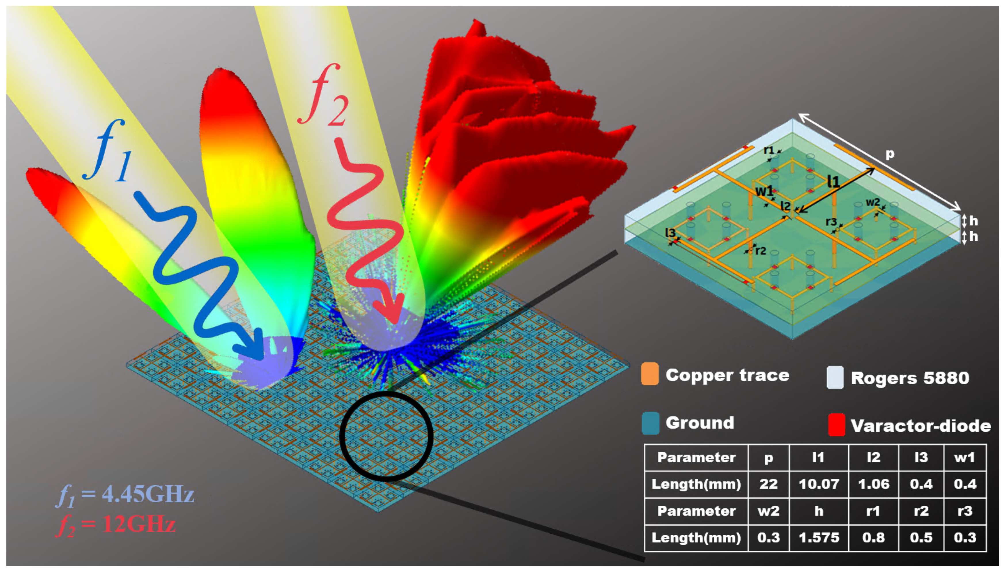
Figure 1 shows the overall layout of the proposed dual-band CP RIS, comprising cascaded sub-unit cells. Hereafter, we refer to the sub-unit cell at the bottom as Cell-B and the one at the top as Cell-T. Cell-T and Cell-B are envisioned to operate within the frequency bands of [4.35 GHz–4.5 GHz] and [11.8 GHz–12.3 GHz], respectively. Each sub-unit cell has a compact size of 0.324
(Cell-T) and 0.44
(Cell-B) at their center frequencies, respectively. Additionally, to minimize quantization losses, four varactor diodes (MAVR-0110201411) are integrated into both Cell-T and Cell-B, thereby achieving continuous tunability. To cascade these unit cells, RO2929 bondply is used, with perforations introduced in the regions containing diodes to facilitate effective bonding. In the simulation environments, these diodes are modeled as lumped circuit elements, each with a series resistance of 13.2
and a capacitance tunable from 0.04 pF to 0.24 pF [
37]. Each varactor diode is biased through a biasing via to vary its capacitance. Specifically, the capacitances of the varactor diodes that are integrated with Cell-T and Cell-B are denoted as
and
, respectively. Additionally, it should be noted that the proposed unit cells are also symmetrically structured so that two orthogonal polarizations can be tuned and allow circular polarization operation.
Notably, these sub-unit cells are suitably arranged and stacked to minimize mutual coupling between them and to ensure band-independent operation. For this purpose, Cell-T (or Cell-B) is deliberately designed not to resonate at the operating frequency band of Cell-B (or Cell-T). This ensures that each sub-unit cell behaves essentially as an open circuit at the other cell’s operating frequency, allowing them to be effectively transparent to each other. Specifically, the band-independent operation is achieved by intentionally designing each sub-unit cell to behave as a non-resonant structure at the operating frequency of the other. This is achieved by ensuring that the physical and electromagnetic interactions between Cell-T and Cell-B are minimized through the spatial separation of their current paths within the window-shaped geometry. As shown in
Figure 2a, when the unit cell is excited at
GHz, the current distribution is confined entirely to Cell-T, with negligible interaction observed on Cell-B. This behavior persists even under varied bias conditions (i.e., different combinations of
and
), indicating that the presence of Cell-B does not perturb the performance of Cell-T. A similar decoupled response is observed at
GHz, as depicted in
Figure 2b, where Cell-T effectively acts as a passive structure. These results confirm that the sub-unit cells function independently across their respective frequency bands, thereby preserving beam performance in one band regardless of the tuning in the other.
Specifically, this can be seen in
Figure 3, which plots the magnitude and phase of the reflection coefficient at
and
. As shown, the tuning of
(or
) does not affect the operation of the dual-band unit cell at
(or
). This implies that
and
are the sole variables for controlling the lower and upper bands, enabling reliable and effective band-independent control of the dual-band reconfigurable unit cell. Specifically, at
, the unit cell achieves a continuous reflection phase shift of 290° with a maximum loss of −3.4 dB. At
, the unit cell induces a continuous reflection phase shift of 300° with a maximum loss of −6.5 dB. Furthermore, to assess the frequency-dependent characteristics of the proposed design within each band, the unit-cell response was analyzed at the two edge frequencies of the lower band: 4.35 GHz and 4.5 GHz. As illustrated in
Figure 4, although the reflection parameters (with respect to the fixed diode capacitance values) exhibit observable variations across the frequency range, the band-independent behavior of the unit cell remains intact. Importantly, however, a wide and continuous tuning range is preserved at both frequencies.
A similar analysis was also conducted for the upper band, with edge frequencies of 11.8 GHz and 12.3 GHz, and comparable behavior was observed, as shown in
Figure 5. Despite some observable variations in the reflection parameters across the frequency span, the unit cell consistently demonstrated independent tunability and a broad, continuous phase-control range. These results confirm that the proposed RIS architecture ensures robust and reliable band-independent operation across both frequency bands.
Meanwhile, it should further be noted that two Cell-B elements exist within one physical period of the surface. Strictly speaking, this implies that the unit-cell periodicity at the upper frequency band is twice that of a single Cell-B. However, as shown in
Figure 2b, the surface current distribution is relatively concentrated on each Cell-B, and independent tuning of each element is feasible. Therefore, we assume pseudo-periodicity in our analysis, wherein the effective periodicity at the upper band is considered equivalent to that of a single Cell-B. The validity of this assumption is confirmed through full-wave simulations presented in
Section 4. Thus, by adopting the concept of pseudo-periodicity, the effective periodicity of the RIS can be significantly reduced. This is particularly beneficial, as previous dual-band RIS designs often exhibit periodicities larger than 0.5
, which can lead to grating lobes and degrade beam-shaping resolution [
38]. At
and
, the corresponding periodicities are 0.44
and 0.324
, respectively. These subwavelength periodicities eliminate grating lobes and allow inducing surface waves along the surface for arbitrary beam shaping beyond simple beam steering [
15].
In what follows, we discuss an arbitrary beam-synthesis method based on the proposed RIS to realize complex far-field patterns based on a GA-based optimization scheme. To enable the practical implementation of the proposed RIS, a feasible biasing architecture must accompany it. In this work, we consider a multilayer PCB configuration, wherein each unit cell is connected via vertical interconnects to a dedicated control layer beneath the RF ground plane. This layer may incorporate radial stubs to suppress high-frequency signals while allowing DC bias lines to be routed independently to each varactor diode. Such an approach minimizes interference with the RF signals and supports precise control of multiple tuning elements per unit cell, as previously demonstrated in [
24].
3. Synthesis of Complex Far-Field Patterns Based on a Genetic Algorithm
In this section, we demonstrate how an array of the proposed unit cells can be utilized to achieve arbitrary beam-shaping capabilities beyond simple beam steering. Specifically, we consider the simultaneous and independent manipulation of normally incident plane waves at two user-defined frequencies to form complex far-field patterns such as dual beams and sector patterns. It should be emphasized that realizing such patterns typically requires independent control of both the amplitude and phase of unit cells to synthesize the effective gain and lossy regions along the surface [
28]. This requirement becomes evident when evaluating the LPCC between the input and output waves. For a normally incident plane wave, the input power distribution along the surface is uniform. In contrast, an arbitrarily shaped output wave, such as a dual-beam pattern, produces a nonuniform power profile at the surface, resulting in inevitable local power mismatches. As such, these mismatches lead to the excitation of unwanted higher-order modes. To mitigate this, lossy regions must be introduced to suppress the unwanted excitations, while gain regions are needed to restore the lost power into the desired output beams. However, as it is difficult to independently control both the reflection amplitude and phase of unit cells, especially at two frequencies, we employ a GA-based optimization technique to synthesize complex far-field patterns with phase-only control. This choice is motivated by the nature of the optimization landscape, which is often highly non-convex. Gradient-based solvers, such as
MATLAB(R2024b)’s
fmincon, typically rely on a certain initial starting point and are thus prone to being confined to limited regions of the search space, potentially yielding locally optimal solutions. In contrast, population-based approaches, such as Particle Swarm Optimization (PSO) and GAs, initiate the search from multiple diverse points, enabling a more global exploration. Although PSO is known for its rapid convergence, its lack of a mutation mechanism—unlike GAs, which introduce abrupt and random alterations in candidate solutions—may hinder its ability to escape from regions of attraction around non-global optima. GAs, on the other hand, employ both crossover and mutation operators, enhancing their ability to escape local traps and explore more complex regions of the solution space. These characteristics make GAs particularly well-suited for robust beam-pattern synthesis under phase-only constraints. The proposed optimization scheme begins with a set of randomly populated phase profiles (i.e., populations) along the surface, and the corresponding far-field patterns of each profile are evaluated based on antenna array theory [
39,
40,
41]. Specifically, the reflected field from the RIS is expressed as a function of the phase profiles as
where
denotes the free-space phase constant,
is the number of elements in the RIS, and
d is the unit-cell periodicity, which is set to 0.326
at
and 0.44
at
. The terms
and
represent the phase and amplitude of the reflection coefficient of the m-th unit cell in the RIS, respectively, which can be obtained from
Figure 3. The parameter
denotes the element pattern of each unit cell, which is derived from the realized gain of the unit cell under periodic boundary conditions by varying the incident angle of the impinging wave. Specifically, this process is implemented using a Floquet mode analysis in ANSYS Electronics Desktop 2024 R2 HFSS [
42]. At this point, it is important to note that the proposed method neglects mutual coupling between dissimilar unit cells. In essence, we adopt a local periodicity assumption, wherein the mutual coupling observed among uniform unit cells is presumed to approximate that of gradually varying, nonuniform unit cells along the surface. There are several methods to incorporate mutual coupling. For example, instead of optimizing metasurfaces locally at the unit-cell level, the whole metasurface can be globally optimized via an integral equation-based formulation [
29,
43]. On the other hand, the impulse response of each unit cell (i.e., a Green’s function) can be numerically extracted to obtain embedded element factors [
44,
45,
46]. While these methods provide an accurate means to synthesize far-field patterns by incorporating mutual coupling, they require full-wave simulations of an entire structure, which is computationally expensive, especially for large structures. In this work, however, we focus on minimizing the computational effort; hence, we adopt the assumption of local periodicity for the element factor
.
Once the far-field patterns are evaluated via Equation (
1) for a given phase profile, they are then compared to a desired pattern with respect to various optimization objectives such as the main beamwidth, beam directions, and side-lobe levels (SLLs). In particular, the cost function for dual-beam generation at
,
, is defined as
where
denotes the set of angles corresponding to the main beam directions of
and
represents the desired main beam locations specified by the user, denoted as
. Additionally,
,
, and
are the weights that are appropriately varied to match
as closely as possible to
. Specifically, for single-beam and dual-beam generation,
,
, and
are set to 0.2, 0.8, and 1, respectively. The optimization process is depicted in Algorithm 1, where we consider P = 100, G = 100, and R = 0.05 for single-beam and dual-beam shaping.
| Algorithm 1: GA-based beam synthesis (multi-beam and sector-beam formation) |
![Electronics 14 02812 i001]() |
On the other hand, in the case of sector-pattern generation, the cost function is defined as
where
represents the main beam direction of
and
denotes the angular range corresponding to the main lobe of the target sector pattern. The parameters
and
denote the central main beam direction and the desired beamwidth, respectively. Finally, as before,
,
, and
represent the weights, whose values are set to 0.8, 0.4, and 1, respectively. The optimization process is also depicted in Algorithm 1, where we consider P = 2000, G = 500, and R = 0.2 for sector-beam formation. Through iterative selection, crossover, and mutation processes, the algorithm evolves the phase profiles by favoring those that yield
. Although the proposed GA-based optimization scheme is capable of finding a global minimum, it is important to note that the optimized
may not exactly match the desired field
when simulated with the corresponding physical structure. This discrepancy arises because the scheme does not account for mutual coupling between unit cells. Nevertheless, as will be shown, the simulated
, based on the optimized phase profiles, exhibits reasonably good agreement with
, despite the proposed scheme neglecting mutual coupling. As such, the proposed approach offers a favorable trade-off between accuracy and computational efficiency.
4. Full-Wave Verification and Surface-Wave Analyses
To further validate the proposed RIS architecture and its design framework, full-wave simulations were performed using ANSYS HFSS, with all Ohmic losses—including those from materials and diodes—included to ensure an accurate representation of the RIS performance. The simulation domain consisted of a single row of the dual-band RIS, composed of 10 Cell-T and 21 Cell-B elements arranged along the x-axis. Periodic boundary conditions were applied along the y-direction to emulate an infinitely wide array, effectively enabling a two-dimensional simulation setup. In particular, we first considered the case wherein two normally incident right-handed circular polarization (RHCP) fields at and were anomalously reflected into a single left-handed circular polarization (LHCP) beam and dual LHCP beams, respectively. Specifically, it was envisioned that the beam at would be steered to , while the one at would split into two beams directed toward and .
Following the outlined GA-based optimization scheme, the required phase profiles at
and
were obtained. These phase profiles were then physically encoded by varying the varactor capacitance, referring to the established one-to-one relation between the varactor capacitance and the complex reflection coefficients at
and
(see
Figure 3).
Figure 6 illustrates the resulting far-field radiation patterns at each operating frequency, where it can clearly be seen that the main beams are directed at the specified angles at both frequencies.
Here, the black dotted lines represent the radiation patterns of the reflected LHCP waves predicted by the GA-based optimization model, while the blue lines correspond to those obtained through full-wave simulation. The close match between the two results confirms that the analytical model was accurately implemented in the simulation, effectively capturing the beamforming capability of the proposed structure. Additionally, the proposed RIS successfully operated with CP waves, as evidenced by the axial ratio of 7.52 dB for the single beam at
. While this axial ratio indicates that there is room for improvement in polarization purity, the reflected cross-polarization component remained sufficiently suppressed to confirm circular polarization behavior. Specifically, the reflected cross-polarization field (i.e., an RHCP component), shown as the red solid line in
Figure 6a, lies well below the peak of the co-polarized LHCP component. On the other hand, at
, the axial ratios are 1.74 dB and 2.12 dB for the beams steered to
and
, respectively, indicating stronger circular polarization performance in the higher-frequency band.
For another beam-shaping demonstration, a more complex scenario was considered, wherein dual-beam formation was implemented at
, while a sector beam was realized at
. In this case, the two beams at
were steered toward elevation angles of
and
, respectively, while a sector-beam pattern was designed to span the elevation angle range from
to
at
.
Figure 7 shows the full-wave simulation result corresponding to this scenario. At
, distinct dual-beam steering was achieved toward the specified elevation angles, while
successfully formed a sector beam covering the desired angular region. The strong agreement between the analytical model (black dotted lines) and the full-wave simulation results (blue lines) again validates the accuracy of the proposed model, even in this complex beam-shaping case. Additionally, the axial ratios were 6.7 dB at
and 5.7 dB at
at
. Furthermore, at
, the average axial ratio within the range of
was measured to be 1.68 dB, indicating excellent circular polarization behavior at
.
Finally, to further emphasize band-independent operation, we modified only the sector pattern at 12 GHz. Specifically, the biasing of Cell-T at was kept unchanged, whereas the biasing of Cell-B at was adjusted so that the resulting sector beam now spanned the angular range from to .
Figure 8 presents the corresponding radiation patterns for this scenario. As observed, the analytical model (black dotted lines) aligns well with the simulated results (blue lines), thereby validating the accuracy of the proposed model. Furthermore, the radiation patterns clearly demonstrate that the desired sector beam spanning from 20° to 40° at
was successfully achieved, while the dual-beam configuration at
was preserved, with beams directed toward
and 40°, as intended. As shown in
Figure 7a and
Figure 8a, the radiation pattern at
remained unchanged even when the biasing configuration of Cell-B was modified to generate different beam directions at
. This clearly indicates that the tuning of Cell-B had no influence on the performance of Cell-T at
. Such results strongly support the complete decoupling between the two sub-unit cells, thereby validating the band-independent operation of the proposed dual-band RIS at both the element and array levels. Finally, the circular polarization characteristics of the proposed RIS were also maintained under this configuration. At
, the axial ratios were measured to be 6.7 dB at
and 5.7 dB at
. Meanwhile, at
, the average axial ratio over the sector beam spanning from
to
was found to be 1.16 dB, confirming robust circular polarization behavior at
.
To further assess the robustness of the proposed dual-band RIS design under practical variations, we examined the effect of deviations in the angle of incidence.
Figure 9 shows the full-wave simulation result when the incident angle was varied by ±10°.
As shown, the main beam direction shifted by approximately ±10° in accordance with the theoretical expectation based on antenna array principles. However, the overall shape of the radiation pattern remained essentially unaffected. This confirms that the proposed RIS maintained stable performance even under deviations in the angle of incidence. This reinforces the practical viability of the proposed RIS architecture, demonstrating that beamforming accuracy is preserved despite moderate angular perturbations. At this point, it is important to note that the demonstrated beam-shaping cases do not appear to satisfy the LPCC. For instance, when comparing the input power distribution of a normally incident beam to the output power distribution corresponding to a sector pattern or dual beams, it is evident that they do not match. However, the full-wave simulation results indicate that these beams can still be accurately formed without significant excitation of spurious modes. This is because the LPCC in the proposed RIS is effectively satisfied through the excitation of surface waves, which redistribute energy across the aperture. The presence of these surface waves can be confirmed by analyzing the spatial frequency components of the aperture field using a Fourier transform.
Specifically, through full-wave simulations, the aperture field at 4.45 GHz was obtained at the center of the unit cell, whereas at 12 GHz, it was sampled at a location offset by one-quarter of the unit-cell periodicity. In both cases, the field was sampled 0.15 mm above the surface along the
x-axis. The total scanning range was 1.3 times the aperture length, resulting in 2001 samples taken at 0.15 mm intervals. The Fourier transforms of these aperture fields are illustrated in
Figure 10 for both dual-beam and sector-pattern generation at
and
, respectively. As shown, strong spatial frequency components exist beyond the visible region—that is, within the evanescent spectrum—indicating the presence of surface waves. These surface waves facilitate lateral power transfer across the surface, allowing the desired far-field patterns to be successfully synthesized despite local power mismatches.


