Article

Design of Ultra-Wideband Low RCS Antenna Based on Polarization Conversion Metasurface

1
School of Physics and Electronic Information, Yan’an University, Yan’an 716000, China
2
Shaanxi Key Laboratory of Intelligent Processing for Big Energy Data, Yan’an 716000, China
3
Key Laboratory of Advanced Optoelectronic Materials and Devices of Higher Education Institutions in Shaanxi, Yan’an University, Yan’an 716000, China
*
Author to whom correspondence should be addressed.
Electronics 2025, 14(11), 2204; https://doi.org/10.3390/electronics14112204
Submission received: 6 March 2025 / Revised: 13 May 2025 / Accepted: 27 May 2025 / Published: 29 May 2025

Abstract

:
An ultra-wideband and radar cross-section (RCS) antenna array based on polarization conversion metasurface (PCM) is proposed. Firstly, the PCM unit is proposed, and its performance is analyzed. In terms of radiation performance, the −10 dB impedance matching bandwidth of the PCM unit is 8.5–30.2 GHz (a relative bandwidth of 112.1%) and the polarization conversion ratio (PCR) is higher than 90%. In terms of scattering performance, the antenna achieves more than 10 dB RCS reduction in the band of 8.35–30.45 GHz (a relative bandwidth of 113.9%). Secondly, the PCM unit is combined with the microstrip antenna, and its performance is analyzed: the gain of the microstrip antenna is increased by 2.8 dB at 19.5 GHz compared to the antenna without the PCM, and the low-RCS antenna array achieves RCS reduction over 6 dB within the frequency range of 8.3–31.7 GHz (a relative bandwidth of 117%). The antenna array has the advantages of wide bandwidth, high gain, and low RCS. It can be used for radars, aircraft, and stealth platforms.

1. Introduction

At present, in the complex and challenging warfare environment, communication systems serve as an important support of modern warfare. Among them, the antenna is the core device for transmitting and receiving signals. Its performance is directly related to the quality and stability of communication. In the context, in-depth research on the stealth performance of antenna is of great significance to promote the development of the communication industry to a higher level.
With the development of target detection technologies, stealth technology is faced with great challenges. Wider stealth frequency bands and lower RCS have become research hotspots for scholars [1,2]. In stealth platforms such as radars and aircraft, the RCS reduction of antenna has become a new challenge due to the huge scattering caused by the large aperture of the antenna array [3]. Traditional methods of antenna RCS reduction include changing the antenna shape [4], loading absorbing materials [5], loading Frequency Selective Surfaces (FSS) [6,7,8], loading Artificial Magnetic Conductors (AMC) [9,10,11], and other methods. Changing the antenna shape mainly involves removing some metal parts to reduce the antenna’s RCS but will cause the gain attenuation and pattern distortion of the antenna. When the absorber material is used as the antenna medium to absorb the external radar detection wave for achieving the RCS reduction of the antenna, the performance of the antenna will be reduced. Loading EBG structures can achieve excellent antenna RCS reduction, but it will limit the bandwidth of RCS reduction. When FSS is used as a radome or ground plane, it can reflect detection waves in other directions to achieve antenna RCS reduction, but it can only reduce the out-of-band RCS. The plasma antenna is used for antenna radiation by ionizing inert gas and the plasma formed by ionizing the antenna. However, it has high power consumption and cost, so it is used less in reality.
In recent years, the breakthrough development of metamaterial technology provides a new idea for RCS reduction. The new type of artificial composite material with special electromagnetic properties has been widely applied in radar fields. As a 2D form of meta-materials, metasurface can effectively manipulate the phase of electromagnetic waves to achieve RCS reduction and have little impact on the antenna’s radiation performance. The PCM is a widely used type of metasurface. It can adjust the amplitude and phase of incident electromagnetic waves, enabling scattered electromagnetic waves to have different polarization modes. In the field of RCS reduction, the PCM can convert the linearly polarized detection waves of external radars into other polarized waves making the scattered waves of the target object received by the radar weaker, thus achieving the effect of reducing the RCS of the target [12,13]. Generally, PCM has two types: transmissive and reflective. In the field of stealth platforms, reflective metasurfaces have attracted much attention [14,15].
At present, metasurface antennas based on the polarization conversion mechanism have made a series of breakthroughs in the field of broadband RCS reduction. In response to the requirements of broadband RCS reduction, a dumbbell-shaped broadband PCM antenna was proposed in [16] achieving an average RCS reduction of 6 dB in the band of 7–20 GHz. A composite resonant structure consisting of an open square ring and a cross-shaped patch was employed to extend the 10 dB reduction bandwidth to the range of 8.36–23.38 GHz in [17]. A low RCS AMC antenna array with gain enhancement was introduced in [18], achieving an RCS reduction of more than 6 dB in the band of 5.1–6.9 GHz. An antenna array based on frequency-selective absorber RCS is proposed in [19], which achieves a gain of 14.9 dBi at 5.3 GHz and the RCS reduction of more than 10 dB in the band of 3.15–8.75 GHz. A wideband circularly polarized antenna was crafted using four orthogonal bilayer structures, achieving an out-of-band in-band RCS reduction of more than 10 dB in the band of 6.6–22.4 GHz in [20]. Four orthogonal metasurface elements arranged in a 2 × 2 array to achieve RCS reduction of more than 6 dB in the operating frequency band in [21]. In this paper, an antenna array that combines the PCM with the microstrip antenna is proposed. The PCM unit achieves an ultra-wideband performance of 112.1% by adding an air layer. After loading the PCM unit, the gain of the microstrip antenna is increased by 2.5 dB achieving the RCS reduction of more than 6 dB in the band of 8.3–31.7 GHz. The antenna array can be used in covert communication systems in the X-K band.

2. Antenna Unit Design and Simulation
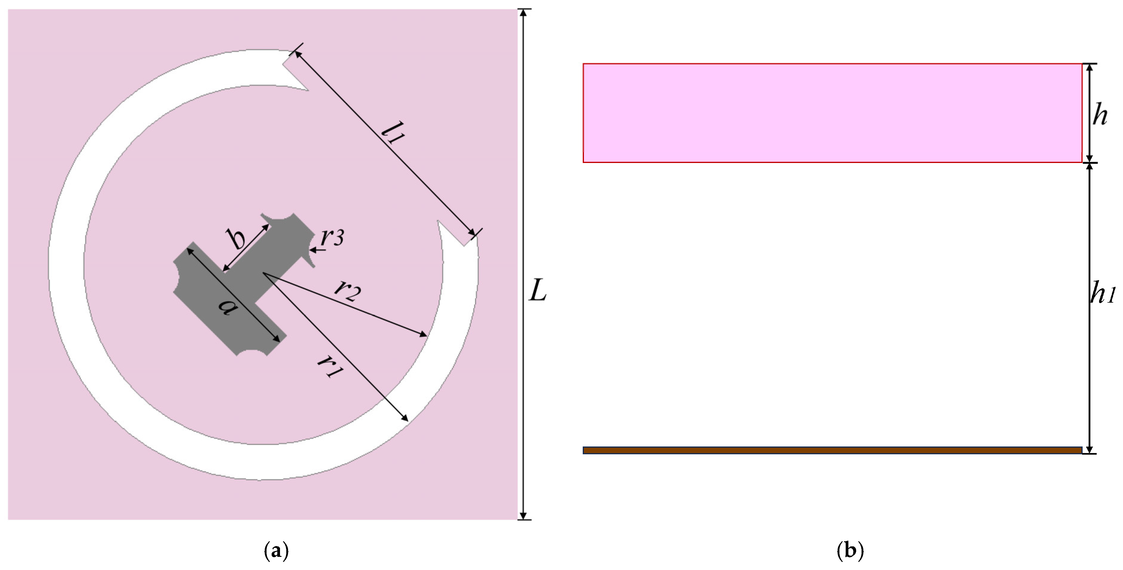
2.1. PCM Unit

Figure 1 shows the structure of the PCM unit. The antenna structure is composed of a metal patch, a dielectric substrate, and a metal ground plane. The metal patch consists of an external opening ring as well as an internal “cone”-shaped patch. The dielectric substrate is made of TLY-5 ( ε r = 2.2 , tan δ = 0.0009 ) with a thickness of h. An air layer of height (h1) is added between the dielectric substrate and the metal ground plane aiming to broaden the bandwidth of the PCM unit. The specific parameters of the antenna unit are shown in Table 1.

2.2. PCM Unit Performance

The trend of reflection coefficient of the antenna with the height (h1) of the air layer in Figure 2. As can be seen from Figure 2a, increasing the air layer can improve the impedance bandwidth of the antenna. When h1 = 2.7 mm, the antenna has resonant points at 9 GHz, 12.8 GHz, 20 GHz, and 28.7 GHz. The −10 dB impedance bandwidth is 8.5–30.2 GHz (112.1%). Figure 2b shows that the cross-polarization reflection coefficient is closer to 0 dB as the air layer increases. Increasing the air layer changes the resonant current of the antenna and reduces the effective quality factor of the antenna, so as to achieve the effect of broadening the antenna bandwidth.
Figure 3 shows the surface current distribution of the antenna at different frequencies. When f = 9 GHz, the reverse current between the opening ring and the ground plane produces magnetic resonance, while the co-directional current between the inner cone structure and the ground plane generates electrical resonance. When f = 12.8 GHz, the co-directional current between the patch and the ground plane generates magnetic resonance, effectively extending the high band performance. When f = 20 GHz and f = 28.7 GHz, the opening ring generates electrical resonance in the same direction as the current of the ground plane and the reverse current of the inner cone structure produces magnetic resonance. The dynamic control mechanism of multiple resonance points broadens the relative bandwidth of the PCM unit.
In order to better reflect the polarization conversion performance of the PCM unit, the PCR is introduced as a key performance indicator, which is defined as follows:
P C R = r c r o s s 2 r c r o s s 2 + r c o 2
where r c r o s s denotes the cross-polarized reflection coefficient and r c o represents the co-polarized cross-polarization coefficient. The simulated results of the PCR of the PCM unit are shown in Figure 4. In the band of 8.5–30.2 GHz, the PCR values are all more than 90%, which indicate that the PCM unit has excellent polarization conversion performance.

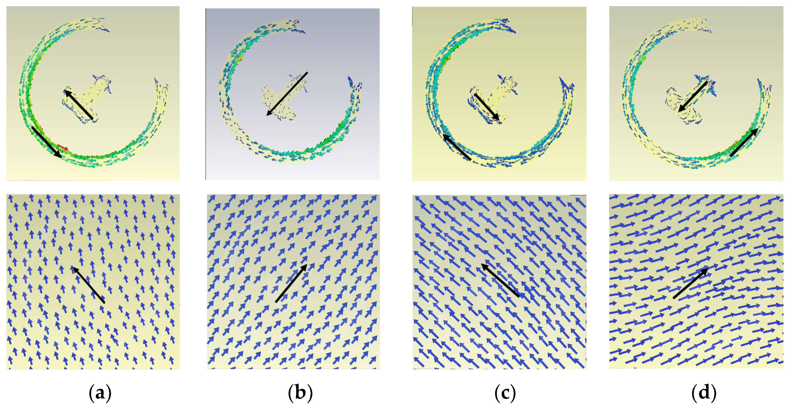
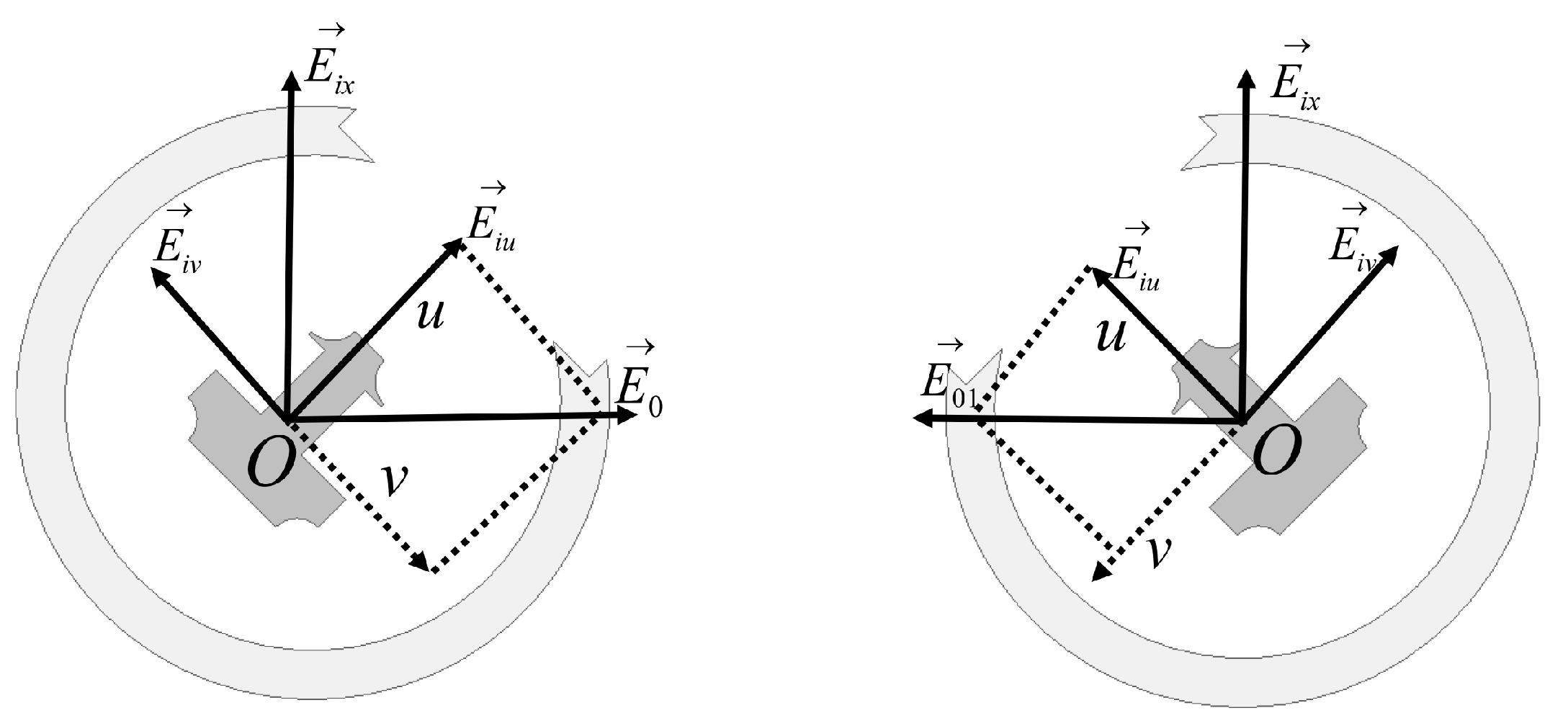
2.3. The Principle of RCS Reduction

The RCS reduction principle of the PCM is shown in Figure 5. Supposing an x-polarized wave impinges perpendicularly on the antenna unit, the electric field vector is represented as E i x . Usually, the v-axis and u-axis are defined by rotating the x-axis forward by 45° and 135° respectively. The electric field is then decomposed into two components E i u and E r v along the u-axis and v-axis. After reflection from the PCM unit, the PCM unit exhibits ideal electric conductor boundary properties in the v-direction, leading to a phase inversion E i v resulting in E r v . Simultaneously, it exhibits an ideal magnetic conductor boundary of properties in the u-direction, maintaining both the amplitude and phase of E i u resulting in E r u . The vector combination of E r v and E r u results in E 0 , whose amplitude is the same as that of the incident wave E i x , while the phase difference is 90°. Similarly, the mirror unit of the PCM reflects E i x to obtain a reflected wave E 01 arranging these units in a checkerboard pattern. When the x-polarized wave is incident vertically to the checkerboard structure, the PCM unit and the mirror unit will produce a pair of reflected waves E 0 and E 01 of equal amplitude, which cancel each other out and realize the RCS reduction.
Figure 6 shows the phase diagram of the PCM unit. Figure 6a depicts that the black color is used to represent the reflected phase of the PCM unit, while the red color represents the reflected phase of its mirror unit. The difference between these two phases is shown in Figure 6b. As evident from Figure 6b, the PCM unit and its mirror unit maintain a 180° phase difference throughout the frequency band. This effectively validates the principle of phase cancelation that is essential for reducing RCS within the PCM. It thereby lays the foundation for the subsequent checkerboard arrangement of PCM units to achieve RCS reduction.

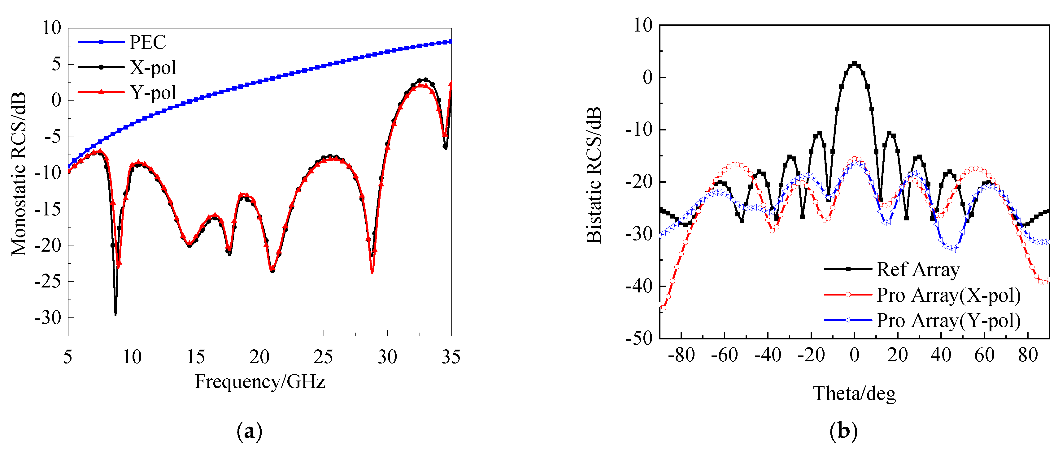
3. Antenna Scattering Performance
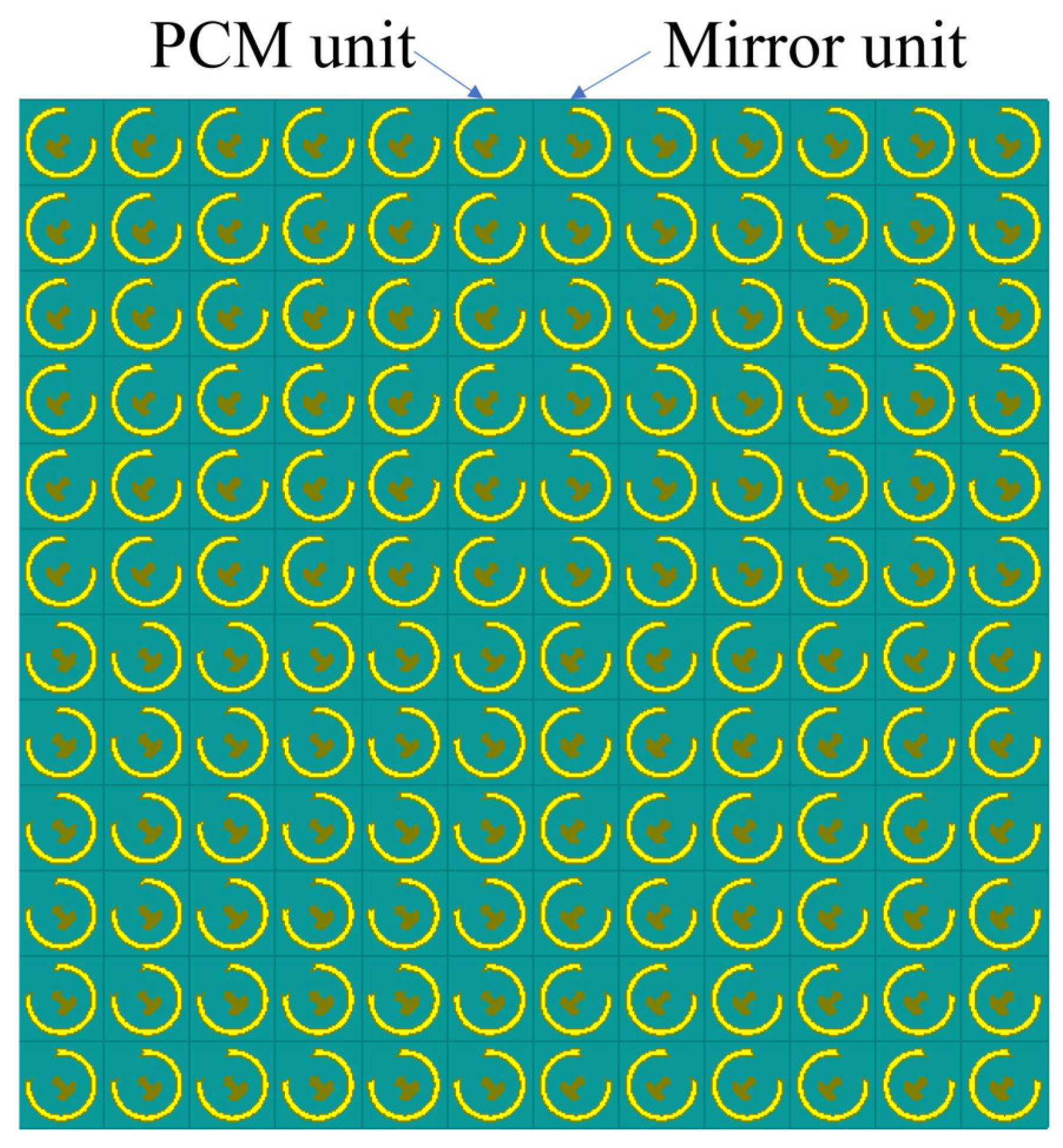
3.1. Antenna Array

The PCM units and its mirror unit are arranged in the checkerboard structure to form a 12 × 12 antenna array as shown in Figure 7. The checkerboard structure consists of 64 antenna units arranged on the Taconic TLY ( ε r = 2.2 , tan δ = 0.0009 ). The overall sizes of the checkerboard structure are 84.4 mm × 84.4 mm × 3.21 mm.
When the antenna array is vertically illuminated by an X-polarized wave and a Y-polarized wave, the variation of its monostatic RCS with frequency is shown in Figure 8a. The monostatic RCS of the antenna array is significantly reduced in the band of 5–35 GHz (150%). The RCS reduction is more than 10 dB in the band of 8.35–30.45 GHz (113.9%). Figure 8b reflects the trend of the bistatic RCS of the antenna array. As can be seen, the antenna achieves RCS reduction in the range of (−45°, 45°) under the illumination of X- and Y-polarized waves. When Theta = 0°, the maximum RCS reduction is 17 dB and 16.8 dB, respectively.

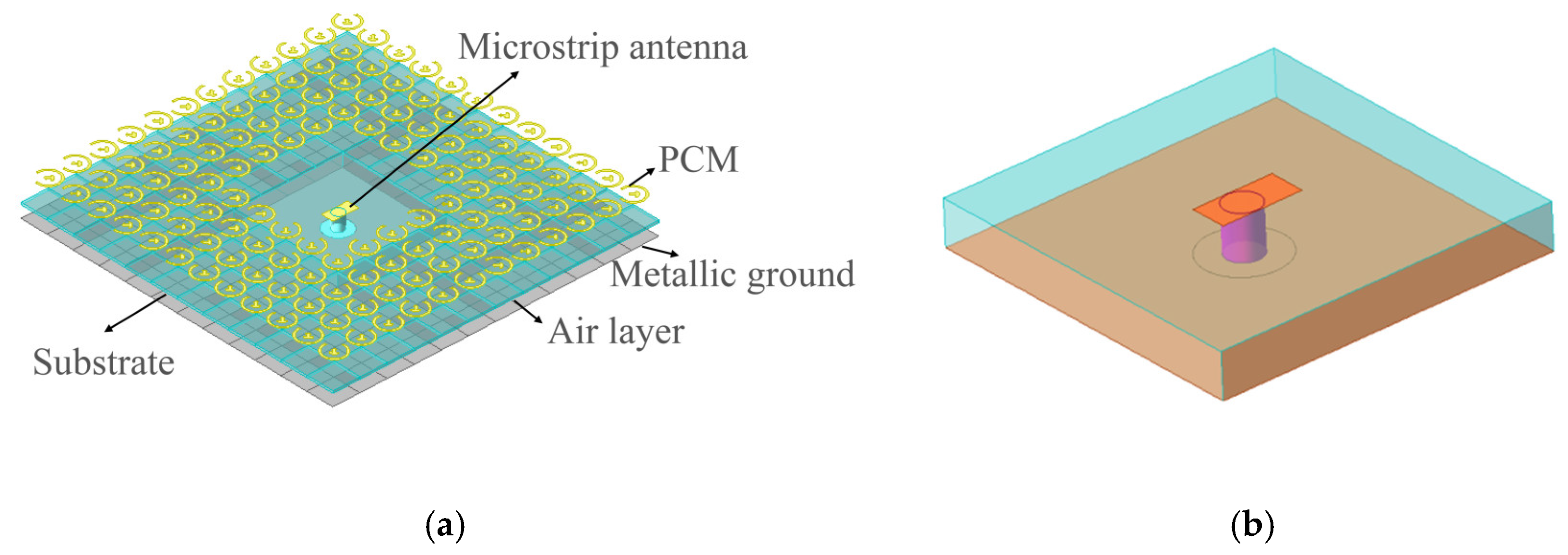
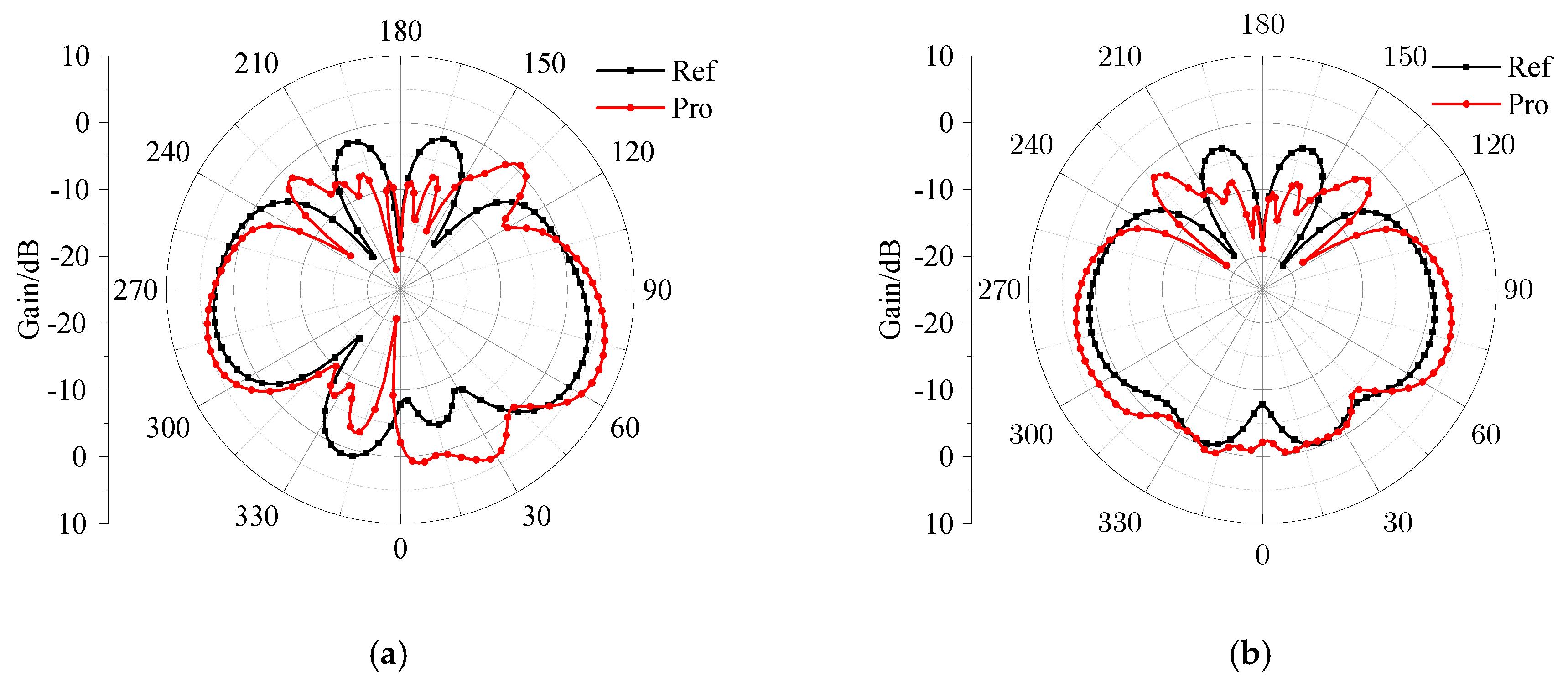
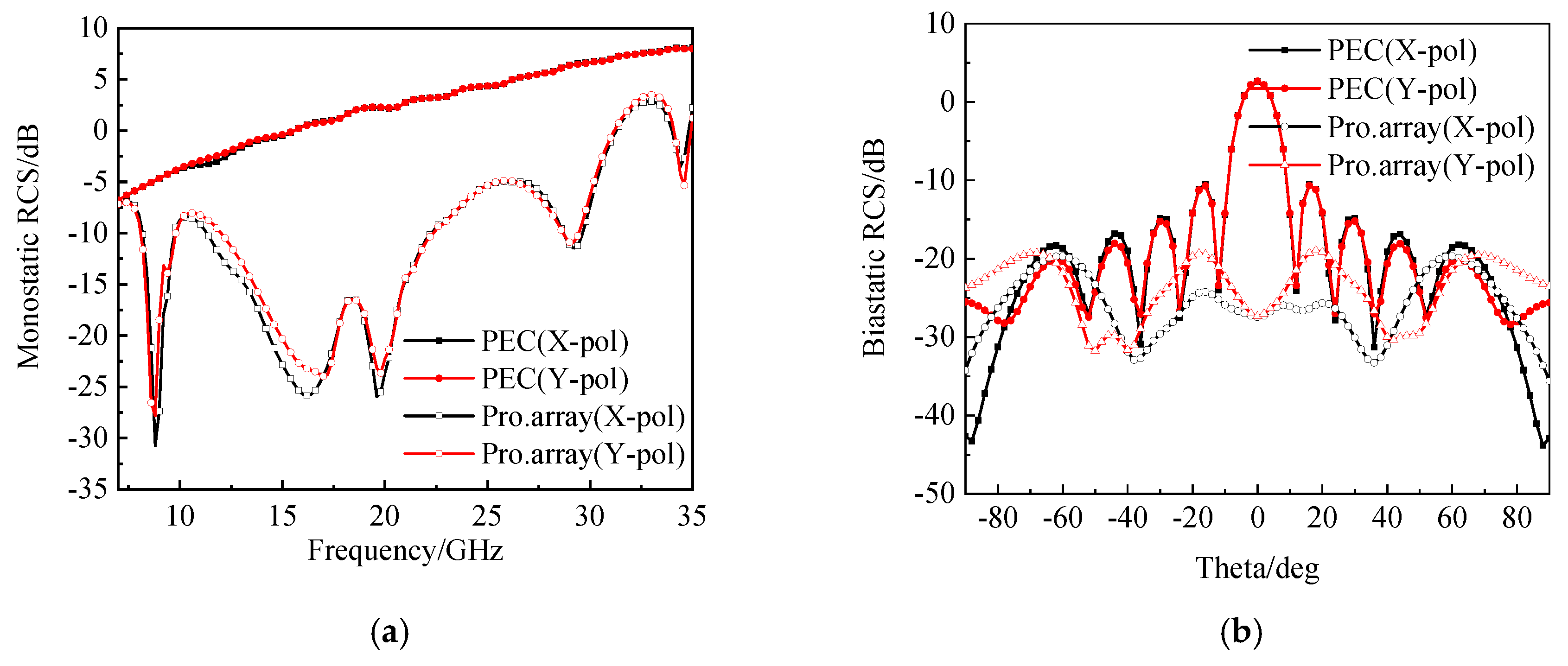
3.2. Load a Low RCS Antenna for Polarization Conversion Metasurface

The RCS array is composed of PCM and microstrip antenna as shown in Figure 9. The PCM units and the microstrip arranged according to the checkerboard structure to build the proposed antenna array. The microstrip antenna uses the Taconic TLY ( ε r = 2.2 , tan δ = 0.0009 ) and feeds by a coaxial line. The proposed antenna array size is 84.4 mm × 84.4 mm × 3.21 mm. The reference antenna size is 24.8 mm × 24.8 mm × 3.21 mm.
The changes in the radiation characteristics of the reference antenna are analyzed. The reflection coefficient of the antenna is shown in Figure 10. After loading the PCM, the impedance band of the reference antenna is shifted, and the effect of impedance matching is weakened. The impedance band of the reference antenna is 12.8–18.4 GHz and the impedance band of the proposed antenna is 12.6–18.6 GHz.
Figure 11 shows the radiation patterns of antenna array in the XOZ plane and YOZ plane at 19.5 GHz. It can be seen from Figure 11a that the gain of the proposed antenna is higher than that of the reference antenna in the range of (0°, 45°). The gain improved by 2.7 dB. The gain of the proposed antenna is higher than the reference antenna within the range of (−55°, 30°) in Figure 11b. The gain improved by 2.8 dB. After loading the PCM, the radiation energy of the antenna is more concentrated, while the radiation performance of the reference antenna is not affected.
The variation of the monostatic RCS of the antenna array under the vertical incidence of X and Y polarized waves is shown in Figure 12a. It is known that the proposed antenna has significant RCS reduction in the band of 7.5–35 GHz (129.4%), of which the RCS reduction band over 6 dB is 8.3–31.7 GHz (117%). Figure 12b shows the variation of the bistatic RCS of the antenna array. Within the range of (−55°, 55°), the bistatic RCS of the antenna is significantly reduced. When Theta = 0°, the maximum reduction of the bistatic RCS is 27.7 dB and 29.4 dB, respectively. The antenna array exhibits excellent RCS reduction performance.
Figure 13 shows the variation of the monostatic RCS of the antenna array with the incident angle at 19.5 GHz. The RCS reduction within the range of (−25°, 25°) is achieved under the TE wave. Under the TM wave, the RCS reduction within the range of (−35°, 35°) is achieved. When Theta = 0°, the maximum monostatic RCS reduction of the are 24.2 dB and 31.9 dB, respectively. The antenna has good monostatic RCS reduction performance.

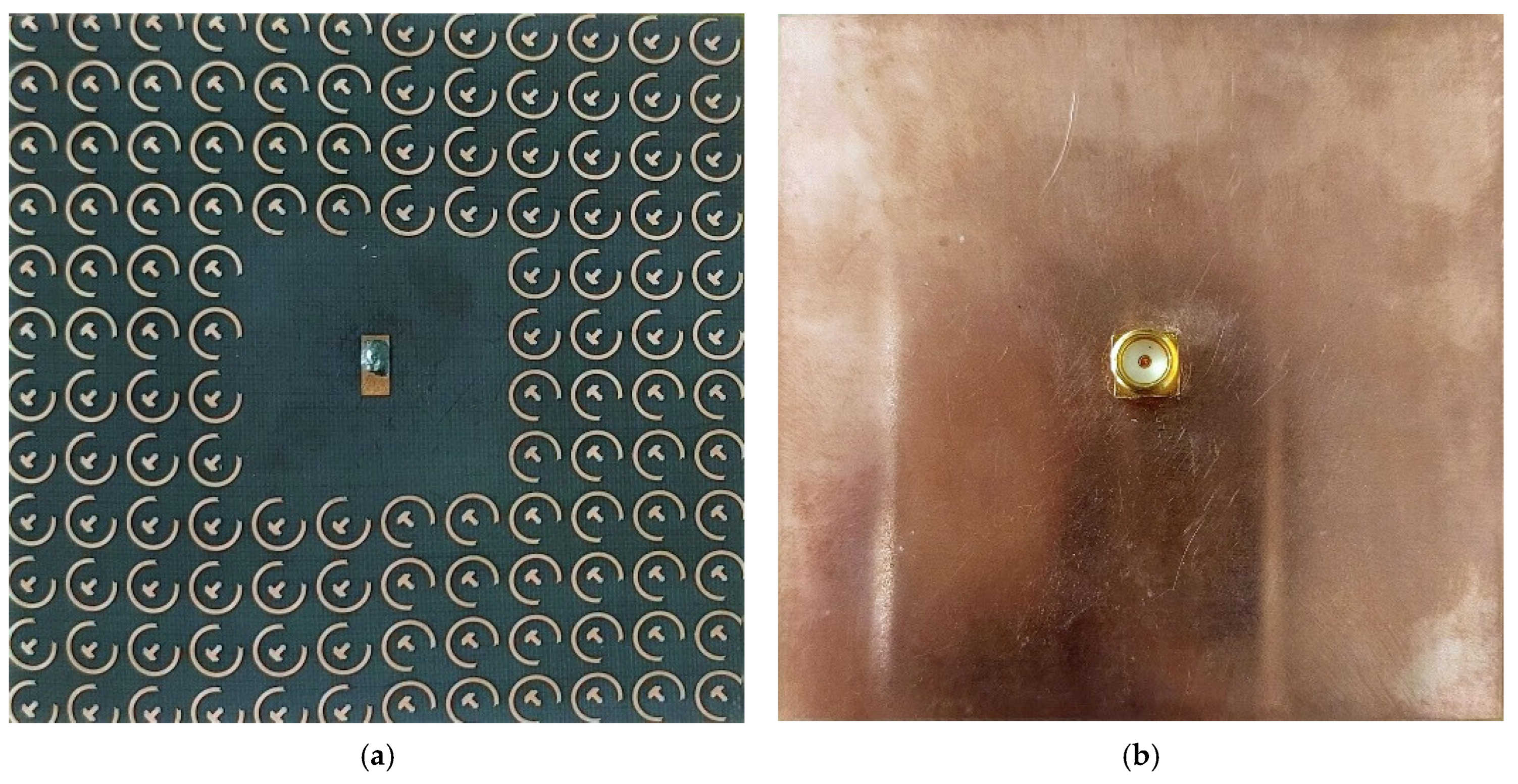
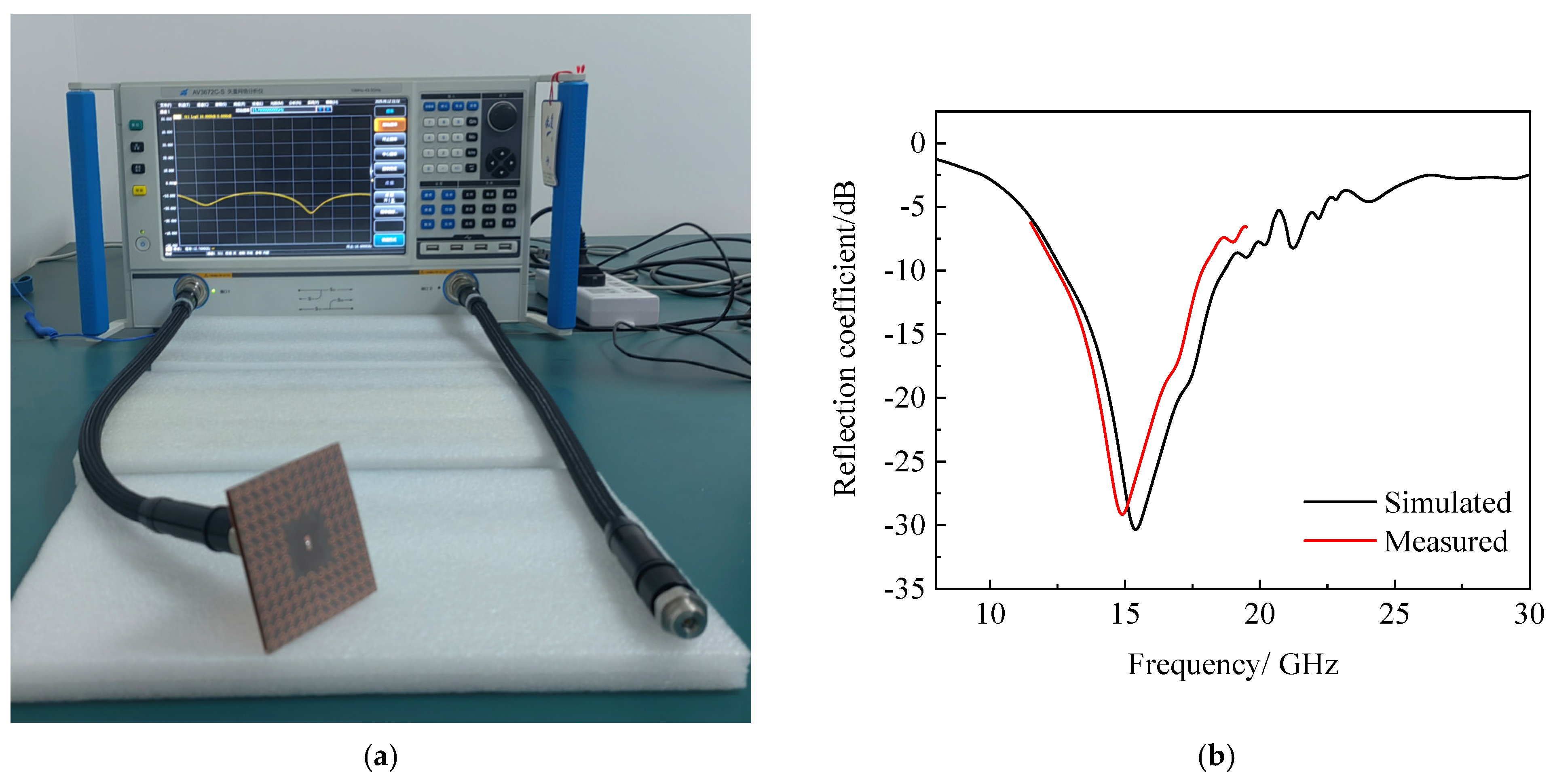
3.3. Physical Picture of the Antenna

A prototype of the proposed array was fabricated as shown in Figure 14. The reflection coefficient measurements of the antenna are shown in Figure 15. The simulated resonant frequency is 15.5 GHz and the measured resonant frequency is 15 GHz. The simulated and measured results are in good agreement considering the measurement errors, such as antenna processing error.
Table 2 shows the performance comparison between the proposed antenna and the existing antennas. Both the existing antennas and the proposed antenna adopt the method of combining PCM with patch antenna. In terms of impedance bandwidth, the proposed antenna performs better than the existing antennas. Regarding the RCS reduction, although its average reduction amount is lower than that of the antennas in [17,18], the RCS reduction bandwidth is better than that of the existing antennas. In terms of the gain, the proposed antenna is lower than the antenna in [19]. Overall, the proposed antenna demonstrates relatively excellent performance in terms of impedance bandwidth, gain, and RCS reduction.

4. Conclusions

In the paper, a wideband, low RCS antenna array based on metasurfaces is proposed. At first, the PCM antenna unit is proposed. Subsequently, the radiation and scattering characteristics of antenna are analyzed. The PCM unit has a relative bandwidth of 112.1% and an in-band RCS reduction of 10dB. Finally, the PCM unit is combined with the microstrip antenna and the PCM units are arranged in a checkerboard structure around the microstrip antenna. Its performance is analyzed. After loading the PCM unit, the XOZ-plane and YOZ-plane gain of the microstrip antenna increased by 2.5 dB at 19.5 GHz. The antenna array achieved a 6 dB RCS reduction in the band of 8.3–31.7 GHz (relative bandwidth of 117%). The antenna has the advantages of wide bandwidth, high gain, and low RCS, which can be attributed to radar, aircraft and stealth platforms.

Author Contributions

Methodology, H.G. and Y.Z.; software, H.G. and J.L.; validation, H.G.; formal analysis, H.G.; investigation, H.G. and Y.Z.; resources, Z.H.; writing—original draft preparation, H.G.; writing—review and editing, Y.Z.; visualization, R.G.; supervision, Z.Y.; project administration, R.G. and Y.Z. All authors have read and agreed to the published version of the manuscript.

Funding

This work was supported in part by the National Natural Science Foundation of China (Grant Nos. 62261054, 62361054 and 62461054), in part by the Shaanxi Key Research and Development Program (Grant No. 2024GX-YBXM-108), and in part by the Research project of Yan’an University (Grant Nos. 2023JBZR-009, GXYQ001 and YSJ2025020).

Data Availability Statement

The original contributions presented in this study are included in the article. Further inquiries can be directed to the corresponding author.

Acknowledgments

The author would like to express his thanks to all tutors.

Conflicts of Interest

The authors declare no conflicts of interest.

References

  1. Xi, Y.; Jiang, W.; Hong, T.; Wei, K.; Gong, S. Wideband and wide-angle radar cross section reduction using a hybrid mechanism metasurface. Opt. Express 2021, 29, 22427–22441. [Google Scholar] [CrossRef] [PubMed]
  2. Fu, C.; Han, L.; Liu, C.; Sun, Z.; Lu, X. Dual-band polarization conversion metasurface for RCS reduction. IEEE Trans. Antennas Propag. 2020, 69, 3044–3049. [Google Scholar] [CrossRef]
  3. Knott, E.F.; Schaeffer, J.F.; Tulley, M.T. Radar Cross Section; SciTech Publishing: Raleigh, NC, USA, 2004. [Google Scholar]
  4. Xu, W.; Wang, J.; Chen, M.; Zhang, Z.; Li, Z. A novel microstrip antenna with composite patch structure for reduction of in-band RCS. IEEE Antennas Wirel. Propag. Lett. 2014, 14, 139–142. [Google Scholar] [CrossRef]
  5. Liu, Y.; Zhao, X. Perfect absorber metamaterial for designing low-RCS patch antenna. IEEE Antennas Wirel. Propag. Lett. 2014, 13, 1473–1476. [Google Scholar] [CrossRef]
  6. Genovesi, S.; Costa, F.; Monorchio, A. Low-profile array with reduced radar cross section by using hybrid frequency selective surfaces. IEEE Trans. Antennas Propag. 2012, 60, 2327–2335. [Google Scholar] [CrossRef]
  7. Kumar, A.; Padhi, J.; Reddy, G.S.; Narayan, S. FSS based Wide Band and Polarization-Insensitive EM Wave Absorber for RCS Reduction Application. In Proceedings of the 2023 IEEE Wireless Antenna and Microwave Symposium (WAMS), Ahmedabad, India, 7–10 June 2023; pp. 1–4. [Google Scholar]
  8. Cheng, Y.F.; Peng, F.; Liao, C.; Ding, X. Broadband Low-RCS Antenna Combining FSS Transmission and Metamaterial Absorption. In Proceedings of the 2021 International Conference on Microwave and Millimeter Wave Technology (ICMMT), Nanjing, China, 23–26 May 2021; pp. 1–3. [Google Scholar]
  9. El-Sewedy, M.F.; Abdalla, M.A. A monostatic and bistatic RCS reduction using artificial magnetic conductor metasurface. IEEE Trans. Antennas Propag. 2022, 71, 1988–1992. [Google Scholar] [CrossRef]
  10. Cheng, Y.F.; Feng, J.; Liao, C.; Ding, X. Analysis and design of wideband low-RCS wide-scan phased array with AMC ground. IEEE Antennas Wirel. Propag. Lett. 2020, 20, 209–213. [Google Scholar] [CrossRef]
  11. Jing, S.; Xu, L.; Su, X.; Wang, L.; Zhang, T. A Low RCS Microstrip Antenna Based on Chessboard AMC Structure in Ku-band. In Proceedings of the 2024 14th International Symposium on Antennas, Propagation and EM Theory (ISAPE), Hefei, China, 23–26 October 2024; pp. 1–4. [Google Scholar]
  12. Zhu, L.; Sun, J.; Hao, Z.; Kuai, X.; Zhang, H.; Cao, Q. A broadband low-RCS antenna based on hybrid mechanism metasurface. IEEE Antennas Wirel. Propag. Lett. 2022, 22, 975–979. [Google Scholar] [CrossRef]
  13. Wang, B.; Lin, X.Q.; Kang, Y.X.; Hu, R.X. Low-RCS broadband phased array using polarization selective metamaterial surface. IEEE Antennas Wirel. Propag. Lett. 2021, 21, 94–98. [Google Scholar] [CrossRef]
  14. Baghel, A.K.; Kulkarni, S.S.; Nayak, S.K. Linear-to-cross-polarization transmission converter using ultrathin and smaller periodicity metasurface. IEEE Antennas Wirel. Propag. Lett. 2019, 18, 1433–1437. [Google Scholar] [CrossRef]
  15. Wang, H.B.; Cheng, Y.J.; Chen, Z.N. Wideband and wide-angle single-layered-substrate linear-to-circular polarization metasurface converter. IEEE Trans. Antennas Propag. 2019, 68, 1186–1191. [Google Scholar] [CrossRef]
  16. Li, Y.; Yang, H. Low-RCS Low-Profile Patch Antenna Using Polarization Conversion Metasurface. In Proceedings of the 2023 International Applied Computational Electromagnetics Society Symposium (ACES-China), Hangzhou, China, 15–18 August 2023; pp. 1–3. [Google Scholar]
  17. Su, Q.; Cheng, Y.; Yin, P.; Cheng, Y.; Chen, L. A Broadband Low RCS Antenna Based on Polarization Conversion Metasurface. In Proceedings of the 2023 IEEE International Symposium on Antennas and Propagation (ISAP), Kuala Lumpur, Malaysia, 30 October–2 November 2023; pp. 1–2. [Google Scholar]
  18. Gao, K.; Cao, X.; Gao, J.; Li, T.; Yang, H.; Li, S. Low-RCS metasurface antenna array design with improved radiation performance using odd-and even-mode analysis. IEEE Antennas Wirel. Propag. Lett. 2021, 21, 421–425. [Google Scholar] [CrossRef]
  19. Zhu, L.; Sun, J.; Xu, G.; Hao, Z.; Cao, Q. An integrated antenna array with broadband, low-RCS, and high-gain characteristics. IEEE Trans. Antennas Propag. 2024, 72, 5408–5413. [Google Scholar] [CrossRef]
  20. Gao, X.; He, L.Y.; Yin, S.J.; Xue, C.H.; Wang, G.F.; Xie, X.M.; Xiong, H.; Cheng, Q.; Cui, T.J. Ultra-wideband low-RCS circularly polarized antennas realized by bilayer polarization conversion metasurfaces and novel feeding networks. IEEE Trans. Antennas Propag. 2023, 72, 1959–1964. [Google Scholar] [CrossRef]
  21. Gao, X.; Yin, S.; Wang, G.; Xue, C.; Xie, X. Broadband low-RCS circularly polarized antenna realized by nonuniform metasurface. IEEE Antennas Wirel. Propag. Lett. 2022, 21, 2417–2421. [Google Scholar] [CrossRef]
  22. Sun, S.; Jiang, W.; Li, X.; Liu, P.; Gong, S. Ultrawideband high-efficiency 2.5-dimensional polarization conversion metasurface and its application in RCS reduction of antenna. IEEE Antennas Wirel. Propag. Lett. 2019, 18, 881–885. [Google Scholar] [CrossRef]
  23. Liu, J.; Li, J.Y.; Chen, Z.N. Broadband polarization conversion metasurface for antenna RCS reduction. IEEE Trans. Antennas Propag. 2021, 70, 3834–3839. [Google Scholar] [CrossRef]
  24. Yao, W.; Gao, H.; Tian, Y.; Wu, J.; Guo, L.; Huang, X. Wideband low-RCS linear polarized array based on miniaturized polarization conversion metasurface. IEEE Trans. Antennas Propag. 2023, 71, 5663–5674. [Google Scholar] [CrossRef]
  25. Zheng, Q.; Liu, W.; Zhao, Q.; Kong, L.; Ren, Y.; Yang, X. Broadband RCS reduction, antenna miniaturization and bandwidth enhancement by combining reactive impedance surface and polarization conversion metasurface. IEEE Trans. Antennas Propag. 2024, 72, 7395–7400. [Google Scholar] [CrossRef]
Figure 1. Configuration of the proposed antenna. (a) Top view; (b) side view.
Electronics 14 02204 g001
Figure 2. Reflection coefficients: (a) Co-pol; (b) cro-pol.
Electronics 14 02204 g002
Figure 3. Surface current of the patch: (a) f = 9 GHz; (b) f = 12.8 GHz; (c) f = 20 GHz; (d) f = 28.7 GHz.
Electronics 14 02204 g003
Figure 4. Polarization conversion ratio.
Electronics 14 02204 g004
Figure 5. The principle of RCS reduction.
Electronics 14 02204 g005
Figure 6. Antenna phase: (a) the phase of the PCM; (b) phase difference.
Electronics 14 02204 g006
Figure 7. Antenna array.
Electronics 14 02204 g007
Figure 8. RCS reduction: (a) monostatic RCS; (b) bistatic RCS.
Electronics 14 02204 g008
Figure 9. Antenna array: (a) proposed antenna; (b) reference antenna.
Electronics 14 02204 g009
Figure 10. Reflection coefficients.
Electronics 14 02204 g010
Figure 11. Radiation pattern: (a) XOZ plane; (b) YOZ plane.
Electronics 14 02204 g011
Figure 12. RCS reduction: (a) monostatic RCS; (b) bistatic RCS.
Electronics 14 02204 g012
Figure 13. Monostatic RCS: (a) TE wave; (b) TM wave.
Electronics 14 02204 g013
Figure 14. Physical picture of the antenna: (a) top view; (b) bottom view.
Electronics 14 02204 g014
Figure 15. Antenna measurement: (a) measurement setup; (b) simulated and measured reflection coefficient of the array.
Electronics 14 02204 g015
Table 1. Antenna dimensions (mm).
Parametersabr1r2r3l1Lhh1
Value1.60.82.62.170.273.16.20.52.7
Table 2. Comparison of existing antennas with those presented in this paper.
Refs Size   ( λ 0 3 ) ConfigurationImpedance BW (GHz)Enhanced
Gain (dB)
RCS Reduction BW (GHz)Methods
[22]1.67 × 1.67 × 0.114 × 144.01–5.070.34.4–13.5 (100% > 5 dB)Patch antenna and PCM
[23]1.76 × 1.76 × 0.1812 × 126.06–6.7519.6–33.1 (110% > 10 dB)Slot antenna and PCM
[24]1.15 × 1.15 × 0.138 × 84.8–6.0Not Given4.3–13.5 (103.37% > 7 dB)Slot antenna and PCM
[25]3.74 × 3.74 × 0.1024 × 246.53–18.632.946.1–18.9 (106% > 6 dB)Patch antenna, MS
This Work3.84 × 3.84 × 0.2012 × 128.5–30.22.88.3–31.7 (117% > 6 dB)Patch antenna and PCM
Disclaimer/Publisher’s Note: The statements, opinions and data contained in all publications are solely those of the individual author(s) and contributor(s) and not of MDPI and/or the editor(s). MDPI and/or the editor(s) disclaim responsibility for any injury to people or property resulting from any ideas, methods, instructions or products referred to in the content.

