Article

Precision Position Servo PMSM Fast-Response Control Based on Trajectory Planning and ADRC

The State Key Laboratory of Power Transmission Equipment Technology, School of Electrical Engineering, Chongqing University, Chongqing 400044, China
*
Author to whom correspondence should be addressed.
Electronics 2025, 14(10), 2062; https://doi.org/10.3390/electronics14102062
Submission received: 19 February 2025 / Revised: 15 May 2025 / Accepted: 17 May 2025 / Published: 20 May 2025

Abstract

:
Trajectory planning and tracking control strategies have a significant impact on the fast and stable operation of high-precision position servo permanent magnet synchronous motors (PMSMs). Therefore, this paper proposes an active disturbance rejection control (ADRC) strategy for high-precision position servo PMSMs based on jerk- and time-optimal trajectory planning. Firstly, in order to meet the requirement of continuous jerk in the positioning process of precision loads, the seventh-degree Chebyshev polynomial is adopted to establish the point-to-point trajectory planning function. Based on the dynamic boundary conditions under the short-term overload of PMSMs, and with the positioning time as the optimization objective, the optimal coefficient of the polynomial is solved through the fast particle swarm optimization (FPSO) algorithm to obtain the trajectory planning function that takes into account both jerk and time performance. Then, the trajectory plan is used as the position loop reference signal to construct a non-cascade second-order ADRC strategy, leading to a position servo PMSM control strategy that combines a second-order disturbance observer and feedback control law. Finally, the experimental platform is set up to verify the proposed method. The results show that, compared with the traditional control methods, the steady-state positioning time of the control strategy proposed under typical working conditions is reduced by 12.5%, and the jerk continuity during the positioning process has also been significantly improved.

1. Introduction

Precision position servo motion systems are widely used in fields such as aerospace, industrial robots, and hard disk storage [1,2], and permanent magnet synchronous motors (PMSMs) have become the main position servo drive motors due to their excellent comprehensive performance [3]. Time-optimal trajectory planning can effectively improve the response speed of the position servo system. Meanwhile, due to the sensitive characteristics of the load to shock and vibration, precision position servo equipment such as optical radar needs to ensure the continuity of jerk during the positioning process [4]. However, the jerk- and time-optimal trajectory planning, as the given signal of the PMSM position loop, still requires good tracking of the trajectory by the motor control strategy to achieve the smooth and rapid operation of the position servo PMSM. Therefore, it is necessary to carry out a smooth and fast-response control strategy for precision position servo PMSMs from the perspective of trajectory planning and tracking strategies.
In the position servo motion system, trajectory planning is often used as the given reference signal of the position loop of the control system, which affects the positioning time, impact, and energy consumption of the servo system [5]. The optimization of the running time under kinematic and dynamic constraints based on S-curve trajectory planning is carried out in [6,7,8]. Aiming at the problem of jerk discontinuity in traditional S-curve trajectory planning, the impact between different sections of the S-curve is changed continuously by improving the jerk model [9]. There are also many studies on time-optimal trajectory planning based on the polynomial trajectory planning of different degrees. A time-optimal trajectory planning method based on quintic Pythagorean Hodograph curves is proposed to realize the smooth and stable high-speed operation of the Delta parallel robot [10]. In order to overcome the problem of jerk discontinuity at the start and end points of low-order polynomials, some works have attempted to build trajectory planning functions by increasing the order of polynomials [11]. Trajectory planning based on the seventh-order polynomial is applied to an inchworm robot [12]. However, in the existing studies, when optimizing and solving the jerk- and time-optimal trajectory planning, the maximum speed and acceleration of the PMSM under the rated long-term operation are often taken as the boundary conditions of the dynamic constraints, and the peak output performance of the rotational speed and torque of the servo PMSM under the short-term overload operation is not considered. This leads to the dynamic constraints based on the rated performance indicators being difficult to fully exert the rapid response potential of PMSMs.
At the same time, the servo system needs to design a control strategy that can make full use of the motor overload performance and realize the stable tracking of the given position of smooth and time-optimal trajectory planning in the servo outer-loop control part. As a representative control method in classical control theory, proportional integral (PI) control has the advantages of a simple structure and clear parameter meaning and is widely used in industrial position servo control systems [13,14,15]. However, under the influence of internal and external disturbances such as sensor signal errors and changes in PMSM parameters, it is difficult for PI control to achieve rapid convergence through parameter adjustment [16]. In order to overcome the above problems, many scholars have proposed a variety of control strategies, such as fuzzy PI [17], sliding mode [18], and improved PI [19,20,21]. But they increase the system complexity [22]. In the closed-loop control of the position servo, the bandwidth of the position loop and the speed loop is much lower than that of the current loop. Under the operating conditions of rapid response, the speed update frequency and accuracy of the speed loop seriously affect the actual tracking effect of the trajectory planning of the servo system when the speed varies over a wide range [19]. Active disturbance rejection control (ADRC) has the advantages of a high degree of freedom of adjustment and fast convergence speed [23,24]. However, few studies have been conducted to improve the performance of the position servo system by combining ADRC with smooth and time-optimal trajectory planning.
Given the issues mentioned above, a smooth and fast-response control strategy for a high-precision position servo PMSM is proposed to achieve full utilization of the output performance of position PMSMs and good trajectory tracking. The main contributions of this paper are as follows: (1) To solve the problem that the traditional dynamic constraint conditions based on rated parameters are difficult to fully utilize the rapid response capability of PMSM, an impact and time-optimal trajectory planning method under short-term overload is proposed. (2) Considering the influence of internal and external disturbances such as sensor signal errors and motor parameter changes under the actual operating conditions, a position-speed non-cascaded ADRC strategy is proposed to achieve good trajectory tracking.
The remaining content of this article is organized as follows: Section 2: solving the impulse and time-optimal trajectory planning based on Chebyshev polynomials; Section 3: establishing a non-cascaded second-order ADRC strategy; Section 4: conducting the experimental tests; and Section 5: presenting the summary conclusion.

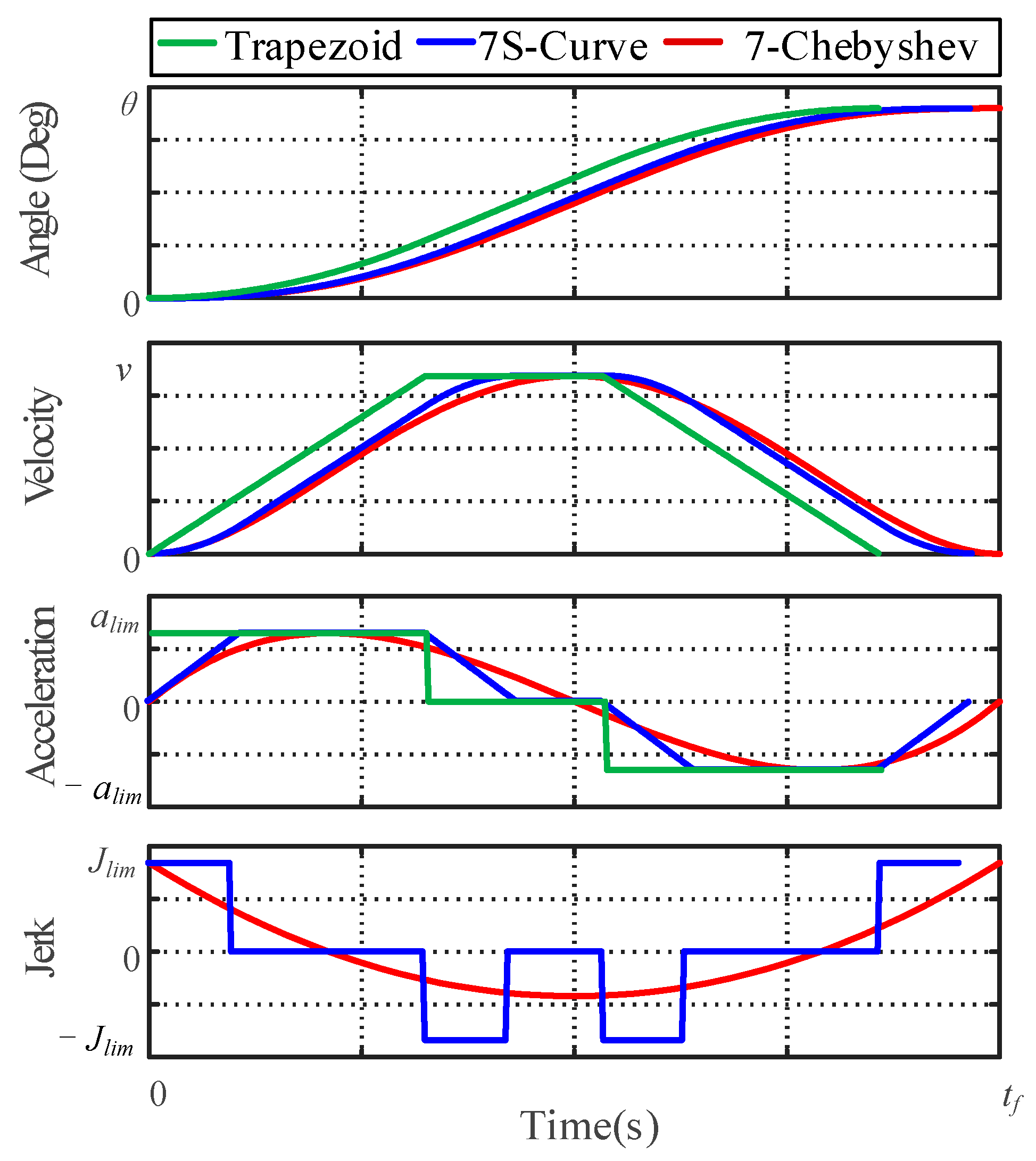
2. Smooth and Time-Optimal Trajectory Planning

2.1. Chebyshev Polynomials

For the drive motor of the position servo system, its speed, position, and output torque have the following dynamic relationship:
J d ω m d t = T e B ω m T L T f T e = 1.5 p n ( ψ d i q ψ q i d ) ω m = d θ m d t
where θm is the rotation angle of the motor; ωm is the mechanical angular speed of the motor; J is the motor rotor and load moment of inertia; B is the friction factor; and TL and Tf are load torque and friction torque, respectively. Considering the influence of frictional torque in the mechanical motion equation will effectively reduce the tracking error of trajectory planning.
It can be seen that the expected electromagnetic torque during the operation of the motor is closely related to the change in the given speed of the motor, and the differential of the speed of the drive system is limited by the maximum value of the motor torque. In actual industry, the S-shaped curve and trapezoidal curve are applied to the trajectory of the servo electric drive system. In this kind of trajectory, the motion process of the servo from the current position to the given position is decomposed into different stages, including acceleration, uniform speed, and deceleration. For each stage, the acceleration changing rate and stage time satisfying the feasible domain are set, and the acceleration, velocity, and position trajectory are obtained through multiple integrations. The acceleration change rate and duration of each stage should be calculated by combining the constraints of the servo system, such as positioning time, energy consumption, and impact.
However, because the direct solution of such trajectory planning is jerk, there is a first-order integral relationship with electromagnetic torque, so higher-order polynomials need to be adopted for trajectory planning. There are more polynomial coefficients considering the constraint of rapidity and a greater amount of calculation. It is difficult to cooperate with the electromagnetic torque control in the calculation process. In order to realize the maximum utilization of PMSM performance, this study selects the seventh-degree Chebyshev polynomial as the basis for trajectory planning, mainly based on its minimum zero-deviation characteristic. Given the number of times, Chebyshev polynomials have the smallest maximum deviation value among all polynomials with the first term coefficient being 1 (minimizing the acceleration jerk in trajectory planning). This feature enables it to demonstrate significant advantages in precision servo scenarios with extremely high requirements for smoothness [25]. With high smoothness, flexible transformation, low coupling degree between parameters, and simple calculation, this trajectory is more suitable for real-time trajectory updating in embedded processors, and it can also realize cooperative control of servo motor electromagnetic characteristics and trajectory planning through the acceleration–torque–current mapping relationship. The Chebyshev polynomials motion trajectory (CPMT) can be widely applied to various types of servo motors.
The mathematical representation of the CPMT is shown in (2):
θ e ( t ) = ϕ ( 2 t / t m 1 ) 0.5 + 0.5 ( θ s θ o ) + θ o ϕ ( t ) = i = 0 n p i T i ( t )                         t , ϕ ( t ) [ 1 , 1 ]
where tm is the servo positioning time; θ0 is the angular coordinate of the starting position; θs is the target angle coordinate; pi is the coefficient of the Chebyshev polynomial; and Ti(t) is the i-order Chebyshev polynomial. Ti(t) can be obtained from the first Chebyshev equation as shown in (3):
T i ( t ) = 1 ,   i = 0 t ,   i = 1 2 t T i 1 ( t ) + T i 2 ( t ) ,   i > 1
The CPMT performs coordinate transformation and inverse scaling of a Chebyshev polynomial, extends its range and definition from the interval [−1, 1] to the starting position of the moving process, and optimizes and updates the trajectory of the moving process by adjusting the tm and polynomial coefficients. Compared with the S-curve or trapezoidal curve, the CPMT parameters are smoother and can be modified and constrained more flexibly.
Taking the 1800° rotation positioning within 0.4 s as an example, based on the same dynamic constraints of the maximum speed and acceleration of the motor, the trapezoidal, S-curve, and 7th-order Chebyshev polynomial are adopted for trajectory planning. The corresponding comparisons of position, velocity, acceleration, and impact are shown in Figure 1. It can be clearly seen from the figure that the 7th-order CPMT can achieve continuous changes in acceleration and impact, while the trapezoid and the S-curve have step changes.

2.2. Servo Pmsm Short-Term Overload Constraints

In servo PMSMs such as turntables and robot manipulators, the load often has certain requirements for instantaneous impact. While improving the operation efficiency as much as possible, the servo PMSM movement trajectory also needs to control the jerk of the whole operation process within the range that the load can bear.
θ e · · ( t ) = ( θ s θ o ) i = 1 n p i T i · · ( 2 t / t m 1 ) a lim θ e · · · ( t ) = ( θ s θ o ) i = 2 n p i T i · · · ( 2 t / t m 1 ) J lim
In addition, the CPMT also needs to satisfy the boundary condition constraints at the start position and the end position. That is, the velocity and acceleration of the starting and ending positions are 0. The kinematic boundary constraints of the trajectory are satisfied by adjusting the polynomial coefficients in the CPMT model.
[ θ e ( 0 ) , θ e · ( 0 ) , θ e · · ( 0 ) ] = [ 0 , 0 , 0 ] [ θ e ( t m ) , θ e · ( t m ) , θ e · · ( t m ) ] = [ θ s , 0 , 0 ]
According to the flux mapping model of a PMSM, the limiting current constraint can be equivalent to the constraint of the limiting electromagnetic torque Tem. It will be constrained by the coefficients of Chebyshev polynomials. Combined with (4), this part of constraint can be characterized as follows:
B θ e · + J θ e · · T em T load ( θ e · · > 0 ) B θ e · + J θ e · · T load + T em ( θ e · · 0 )
During the operation of the servo system, due to the system modulation mode and the DC bus voltage, the stator voltage should be kept within the limit of the power supply voltage of the servo system:
U d 2 + U q 2 U s
In summary, the optimal mathematical model of the CPMT in the servo system motion process is as follows:
min   f ( t m ) = 0 t m 1 d t s . t .     ( θ s θ o ) i = 1 n p i T i · · ( 2 t / t m 1 ) a lim                   ( θ s θ o ) i = 2 n p i T i · · · ( 2 t / t m 1 ) J lim                   ( θ e · ψ q ) 2 + ( R s i q + θ e · ψ d + ψ q · ) 2 < U s 2                   θ e ( 0 ) = 0   ,   θ e ( t m ) = θ s                   θ e · ( 0 ) = θ e · ( t m ) = θ e · · ( 0 ) = θ e · · ( t m ) = 0                   B θ e · + J θ e · · T em T load ( θ e · · > 0 )                   B θ e · + J θ e · · T load + T em ( θ e · · 0 )
In this optimization model, there are dynamic boundary constraints of the position, velocity, and acceleration. At the same time, the mechanical characteristics of the load are constrained by the extreme acceleration value, and there are limits of the voltage and electromagnetic torque. The time-optimal trajectory of the transition process of the servo drive system can be obtained by solving the polynomial parameters and positioning time of the CPMT that minimize the optimization objective function in the solution space satisfying the constraint conditions.

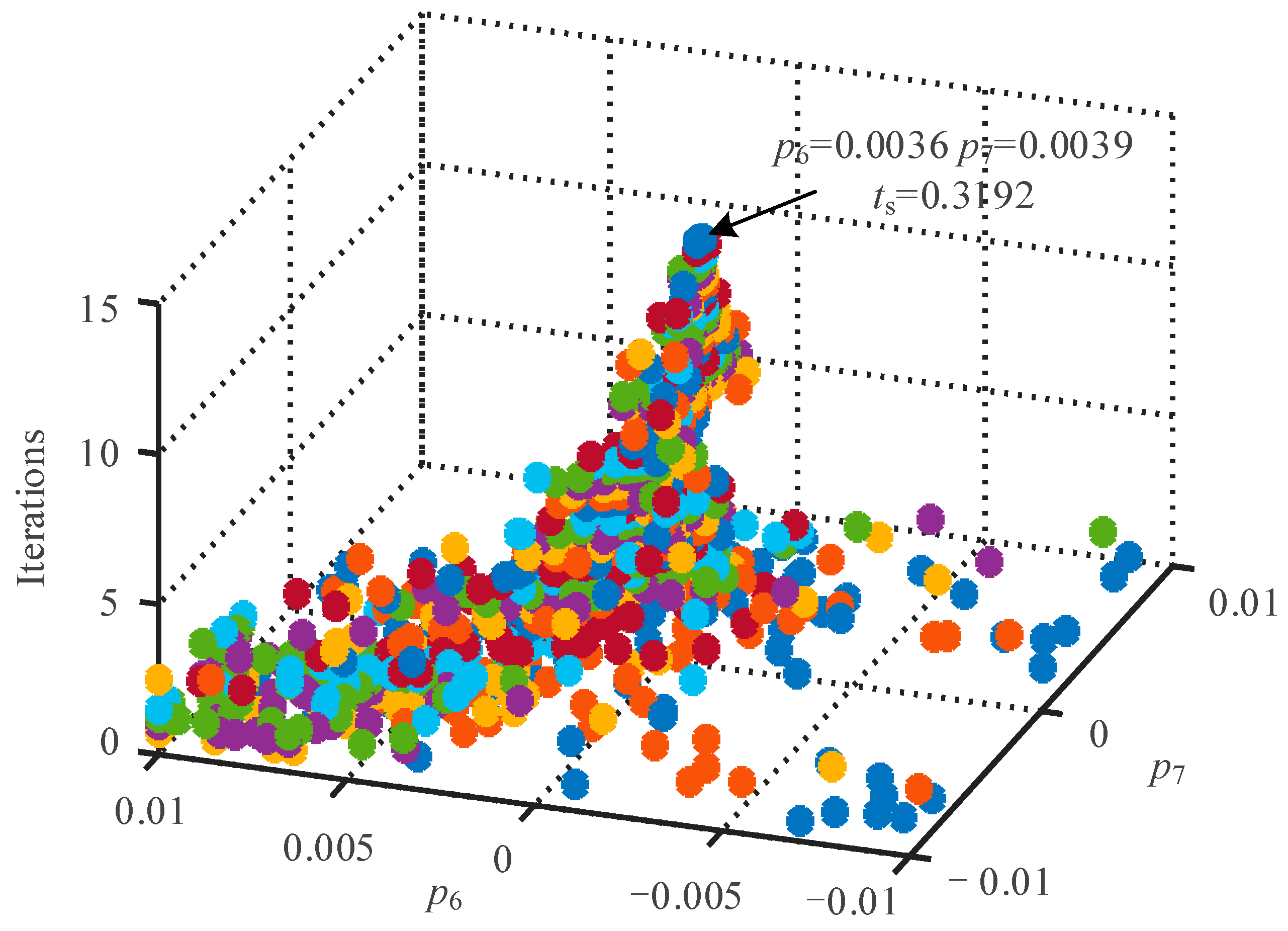
2.3. Optimal Trajectory Solution Based on FPSO Algorithm

The particle swarm optimization algorithm can solve the trajectory with the minimum positioning time under the condition of satisfying the boundary restrictions. In order to achieve the optimization goal of the shortest time positioning in the process of CPMT parameter calculation, it is first necessary to establish a fitness function that can represent the motion efficiency of the servo system to represent the expected positioning time of the CPMT generated by a given parameter. Therefore, different CPMT parameters are evaluated, and the corresponding polynomial parameters to achieve the time-optimal trajectory planning goal are selected. It can be seen from (2) that each Chebyshev term in the CPMT contains a parameter pi to be solved, and the target time tm of the trajectory is also to be evaluated. Many unknowns bring some difficulty to the direct solution, so the original constraint is considered to be properly simplified. By introducing the constraint of (5) into the CPMT and solving some polynomial coefficients, the first 5 parameters in the 7th-order Chebyshev polynomial can be eliminated, and other parameters can be characterized by p6 and p7.
p 0 p 1 p 2 p 3 p 4 p 5 p 6 p 7 = 10 0 0 5 15 0 0 9 6 0 0 5 1 0 0 1 p 6 p 7 + 0 150 0 25 6 3 0 0 1 128
Thus, only unknown quantities p6, p7, and tm remain in the CPMT after partial parameter solution simplification. The original problem is transformed into an optimization problem under the three variables p6, p7, and positioning time tm, whose goal is the shortest positioning time under various constraints.
To achieve the online rapid solution of trajectory parameters under limited computing power, the fast particle swarm optimization (FPSO) algorithm is introduced. Compared with algorithms such as the genetic algorithm and gradient descent, FPSO, as a swarm intelligence stochastic optimization method, has fewer iterations and higher computational efficiency and is suitable for handling the rapid response requirements of real-time systems [26]. In this algorithm, several particles are randomly distributed in a space with each variable as the dimension. During each iteration process, each particle adjusts its running vector according to the local optimal solution and the global optimal solution of the population fitness and continuously iterates to approach the optimal solution.
N particles are configured, and each particle Pi(k) contains three coordinates representing the CPMT substitution under the particle. The speed and position of each particle are iteratively updated according to (10):
V i ( k + 1 ) = ω V i ( k ) + c 1 r 1 ( P b i ( k ) P i ( k ) )                                       + c 2 r 2 ( P g ( k ) P i ( k ) ) P i ( k + 1 ) = P i ( k ) + V i ( k + 1 ) ( i = 1 . N )
In the formula, p6(k), p7(k), and its positioning time tm(k) represent the three dimension coordinates of each particle, where they, respectively, represent the CPMT parameters p6 and p7 of the particle under the current iteration number and its positioning time tm. The detailed steps of the particle swarm optimization are as follows:
(1)
The algorithm parameters are initialized, k = 0 is set, and the iteration parameters such as the inertia factor and learning factor are set;
(2)
N initial particles are randomly generated within the given parameter range, and the particles are distributed within the constraint conditions;
(3)
The local optimal solutions and global optimal solutions Pbi(k) and Pg(k) for each particle are updated;
(4)
The dynamic learning factor parameters are calculated, the particle velocity vector is calculated, and the position information of the next iteration of the particle is updated according to the particle velocity and the current position of the particle;
(5)
After the maximum number of iterations or the global optimal solution remains unchanged after many operations, the calculation is terminated and the CPMT is constructed according to the particle coordinate parameters.
In order to verify the effectiveness of the algorithm, MATLAB 2021b is used for simulation verification. The initial number of particles in the experiment is 20, and each particle contains three dimensions, the inertia factor ω decreases from 0.9 to 0.4, the dynamic learning factor c1 increases from 0.5 to 1.5, and c2 decreases from 2 to 0.5; the maximum number of iteration terminations k is 100. For the main parameter settings, refer to the empirical data and relevant literature [26]. For the two dimensions representing p6 and p7, the optimization range is [−0.01, 0.01], while for the dimension representing ts, the optimization range is [0, 0.5]. The particle distribution and convergence in this process are shown in Figure 2. It can be seen that FPSO can continuously converge to the optimal solution with the increase in the number of iterations, and the algorithm has good convergence.

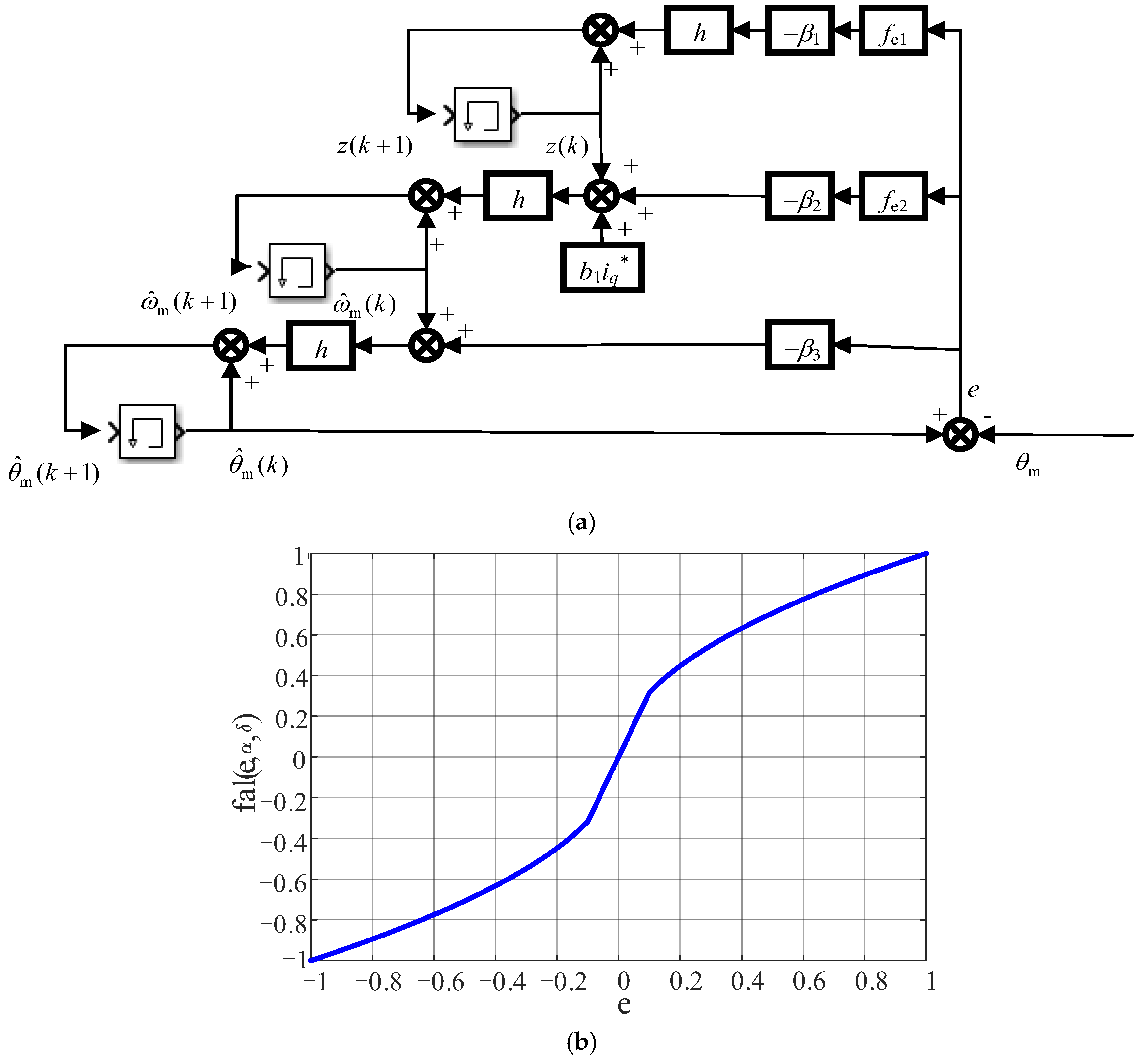
3. ADRC Trajectory Tracking Control Strategy

3.1. Analysisi of Cascading PI Outer-Loop Control

For the servo outer loop, the goal of its closed-loop control is to calculate the output current of the drive system through the interpolation of the given reference input and the actual feedback of the position so as to improve the dynamic response capability and steady-state accuracy of the drive system while minimizing the influence of mechanical parameters such as load, moment of inertia, and friction on the closed-loop control performance.
In the traditional servo control system, if the calculation of speed is not considered, the actual outer ring of the motor is equivalent to the cascade of two closed loops of position and speed. The output of the position controller acts on the control of the inner current loop after passing through the next-level PI as the input to the speed loop. This kind of structure is simple and efficient, and has high robustness and deployment speed in engineering, but the performance of the servo drive system is limited due to the role of the double closed loop. In addition, for the servo drive system based on a position encoder, whether the system is measured by the T method or M method, its speed update frequency and accuracy are difficult to take into account, resulting in a certain impact on the inner-loop reference signal near the update point. Therefore, in this paper, a direct feedback control strategy of position–current is designed by using a non-cascaded second-order ADRC.

3.2. Tracking Control Based on Non-Cascading ADRC

In the servo drive control strategy, the bandwidth of the position loop and the speed loop is much lower than that of the current loop, and as the bandwidth of the closed-loop cascaded system decreases step by step, it leads to the reduction in the rapid control performance of the servo system. Therefore, compared with the traditional three-closed-loop control structure, omitting the speed feedback loop can simplify the control system structure. Based on the second-order ADRC of the servo system outer loop, the current instructions of the inner loop are directly calculated through the input and reference of the position loop, and the servo reference instructions are generated through trajectory planning and the optimal feedforward current setting strategy so as to realize the high dynamic control of the outer loop of the servo system.
Different from the traditional three-closed-loop cascaded control mode of the position–velocity–current, the second-order ADRC controller does not require the introduction of velocity feedback but uses the third-order Extend State Observer (ESO) to observe the velocity from the position feedback and directly output the reference current through the feedback control rate.
It can be seen from (1) that the PMSM is constructed as a second-order system with torque as input and electrical angle as output, and the influence caused by load torque is regarded as a part of the disturbance. Considering the disturbance relationship caused by torque change and inner-loop control error, the equation of state and the total disturbance of the system can be obtained as follows [9]:
θ m · = ω m ω m · = T e J + r s r s = T L / J ( T e * T e ) / J g s
In the servo control process, the traditional strategy adjusts the position disturbance and deviation of the motor through the feedback of the encoder, and there is a certain lag. The ADRC controller can make the control problem equivalent to the active observation and compensation of deviation and disturbance by observing and controlling rs. Therefore, the ADRC servo outer ring design is carried out from three perspectives: transition process introduction based on trajectory planning, error observation, and feedback control rate. In order to make full use of the motor limit performance and improve the smoothness and stability of the system transition process, the traditional tracking differentiator is replaced by the optimal CPMT described in the previous section. The position and speed instructions of CPMT are used as reference signals to the feedback controller, which can give full play to the limit overload torque of the motor through trajectory planning and improve the response ability of the system.
In the design of the ADRC error observer, since the system state variable is a second-order system with disturbance between the position outer loop and the internal current closed loop, the error observer is responsible for observing internal and external disturbances and equivalent disturbances. Therefore, this paper adopts the third-order ESO, and the observer equation of the state can be expressed as follows:
e = θ ^ m ( k ) θ m θ ^ m ( k + 1 ) = θ ^ m ( k ) + h ω ^ m ( k ) β 3 e ω ^ m ( k + 1 ) = ω ^ m ( k ) + h z ( k ) β 2 f e 2 + b 1 i q z ( k + 1 ) = z ( k ) + h β 1 f e 1
where θ ^ m ( k ) and ω ^ m ( k ) are the observed estimates of the mechanical angle and mechanical angular velocity during the k servo outer-loop control period, respectively; e is the observation error; h is the position loop control period; z(k) is the perturbation observed under the k control period; and fe is the nonlinear disturbance value. It can be calculated by the following nonlinear function:
f e 1 = fal ( e , α 1 , δ ) f e 2 = fal ( e , α 2 , δ )
In the formula, the fal function can be expressed as follows:
fal ( e , α i , δ ) = e δ 1 α ,                                           e δ e α sign ( e ) ,                         e > δ
where α is the filter factor of the fal function, and its range is [0, 1]; δ is the filter constant, which affects the filtering effect. Sign is a symbolic function. By extending the internal and external perturbations of the system to a new state, and then using a special nonlinear structure to correct it, a gain with fast-response ability to the perturbations is obtained. The structure has a gain of a small error and large, and can ensure that the gain is maintained in a small range under a large error, so that the amplification effect of the small error can be taken into account and the high-frequency vibration caused by high gain can be avoided. The third-order ESO and fal function block diagram are shown in Figure 3.
In the design of the ADRC’s error feedback rate, the feedback rate is based on the combination of the reference signal generated in the transition process and the error observation signal of the third-order ESO link to establish the control rate, as shown in (15).
e 1 = θ m * θ ^ m e 2 = ω m * ω ^ m T e = fhan ( e 1 , c e 2 , r 1 , k h 1 ) z / b s
where e1 and e2 are error signals and differential error signals, respectively; c is the differential error weight coefficient.
Through the collection of three parts, the design block diagram of the second-order active disturbance rejection servo outer ring can be obtained, as shown in Figure 4. The inner-ring part adopts the flux-free beat control strategy designed above. In the input error control rate when the reference value obtained by trajectory planning differs from the observed value of the third-order ESO, the corresponding torque given instruction output is obtained by combining fhan functions, and the optimal position trajectory of the servo system can be tracked and controlled in the given domain.

3.3. Simulation Verification of Proposed Control Strategy

In order to verify the performance of the non-cascaded ADRC trajectory tracking and control strategy, MATLAB2021b /Simulink simulation verification was carried out. In the simulation verification, the mathematical model of the servo PMSM adopts the basic PMSM model built into the MATLAB2021b /Simulink software and is modified in combination with the electromagnetic parameters of the PMSM studied in this paper. Thus, the focus is on the influence of different trajectory planning and control strategies on positioning smoothness and time. And the response and positioning effects under 1800° travel were analyzed, respectively, through the tracking control strategy mentioned in this paper and the PI cascaded closed-loop control, as shown in Figure 5.
It can be seen from the simulation results that the control strategy based on trajectory planning can achieve trajectory transition and positioning in about 0.42 s, while the PI control under the step command can maintain sufficient response speed in the trajectory ascending stage, but there is a relatively obvious overshoot at the positioning end, and it takes about 0.46 s to complete the final positioning. The reason is that the trajectory of the closed-loop control strategy based on PI lacks sufficient smoothness, and the step rise and fall of the system current in the positioning process leads to a certain overshoot of the inner loop under the influence of the step setting, causing the system oscillation.

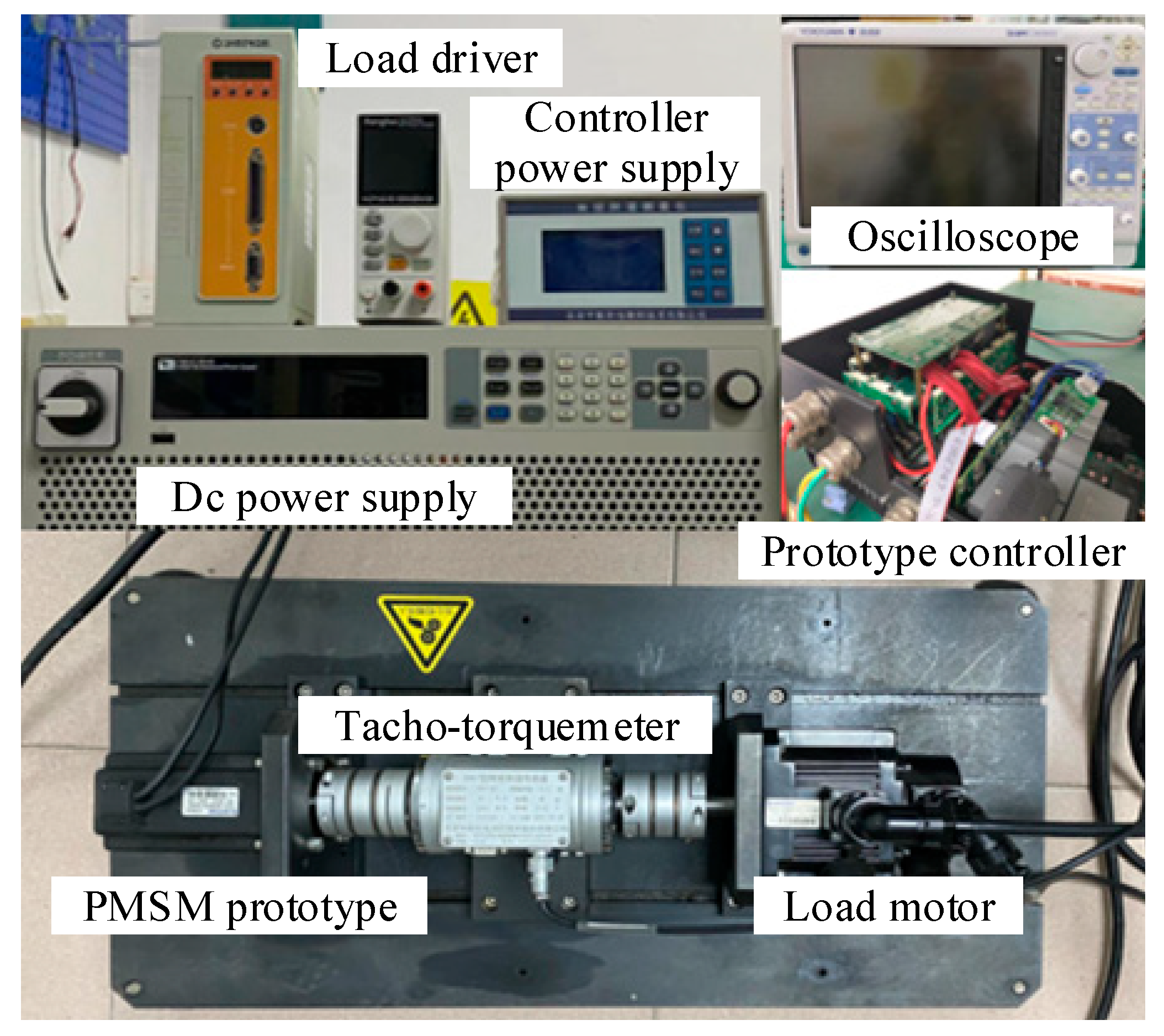
4. Experiment Verification

4.1. Prototype Test Platform

The motor tested in the experiment is a 750 W servo PMSM. The experimental hardware platform built is shown in Figure 6, including the 750 W position servo PMSM, and the 2 kW PMSM is a drag motor used for simulating loads. By applying torque, the actual operating load conditions are simulated, using an experimental frequency conversion controller and load motor frequency converter. The hardware equipment of the experimental platform mainly includes a Yokogawa DL950 digital oscillograph, DC power supply, 2500-line incremental encoder, and voltage and current isolation probe; the DSP controller chip is theTMS320-F28377 dual-core DSP chip of Texas Instruments. Its core function is to process data, run control algorithms and communication programs, and output PWM signals to control the inverter. The software for the acquisition and processing of the test data is Yokogawa IS8000 and MATLAB2021b. The main parameters are shown in Table 1. The shaft of the experimental motor is connected to the torque speed measuring instrument through the coupling for real-time monitoring of the motor speed and torque, while the other end is connected to the PMSM for simulating the motor load, and the load motor is controlled by the supporting frequency converter. A matching 2500-line incremental encoder connection is installed at the tail of the experimental motor for the real-time measurement of the motor position.
The main control chip of the controller adopts the TMS320F28377D dual-core DSP chip of Texas Instruments, which has two parallel cores that can be used for the operation of the control algorithm and communication program. Data transmission and instruction setting are carried out between controller and host computer through communication between the simulator and SCI serial port. CPU1 and CPU2 share memory to realize communication and data exchange between the two cores. CPU1 is responsible for the sampling of the motor position, current, bus voltage, and other signals and executes the operation of the non-cascading ADRC outer loop and the full-flux non-beat inner-loop control program according to the given instructions. After the operation is completed, the system state is written into the GS_RAM shared memory for CPU2 to upload to the upper computer. CPU2 calculates Chebyshev’s motion trajectory and analyzes the received instructions of the upper computer. Data transmission and instruction setting are carried out between the controller and the upper computer through the simulator and SCI serial communication. Among them, RS485 is adopted as the physical layer standard of SCI serial communication for serial communication.

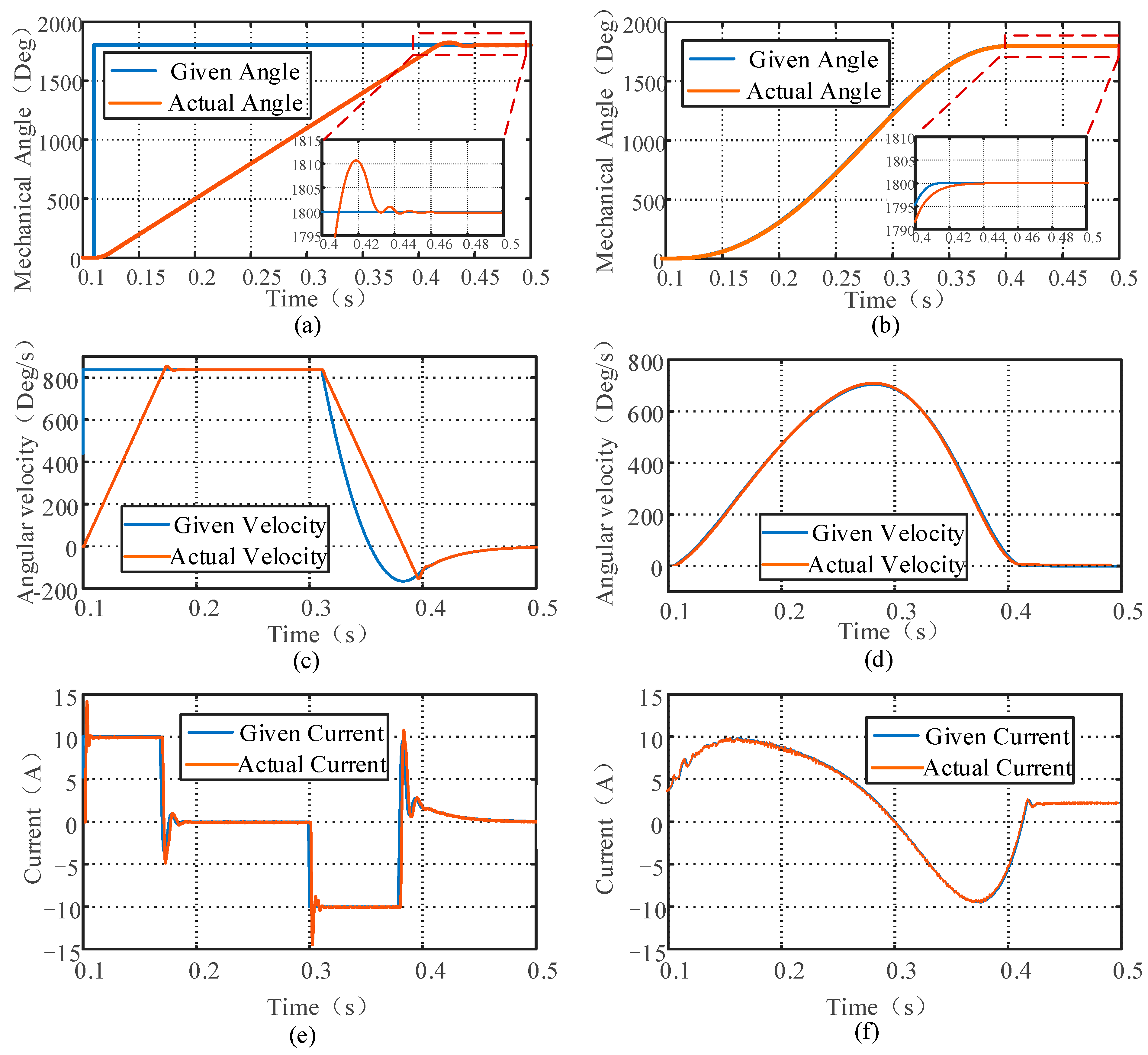
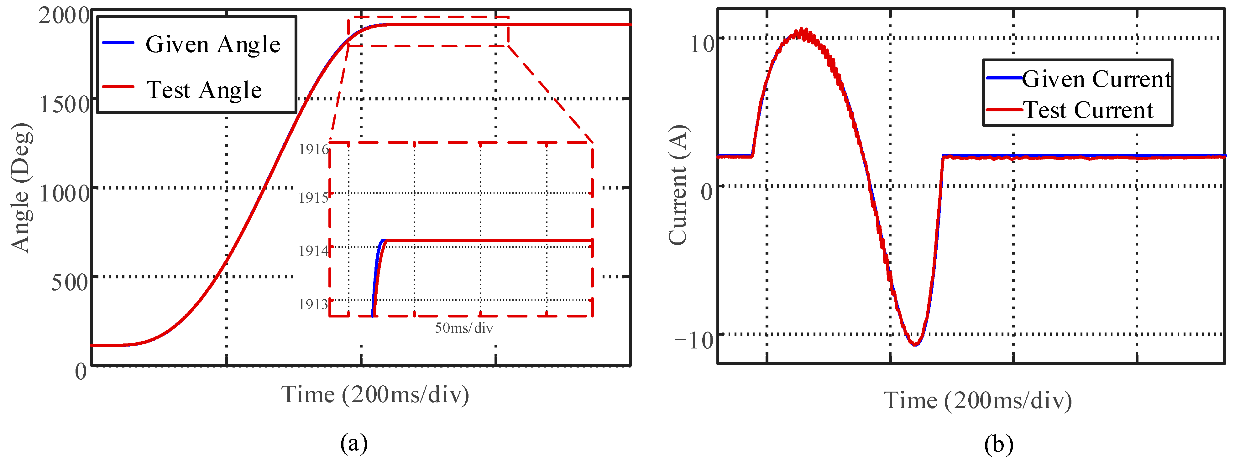
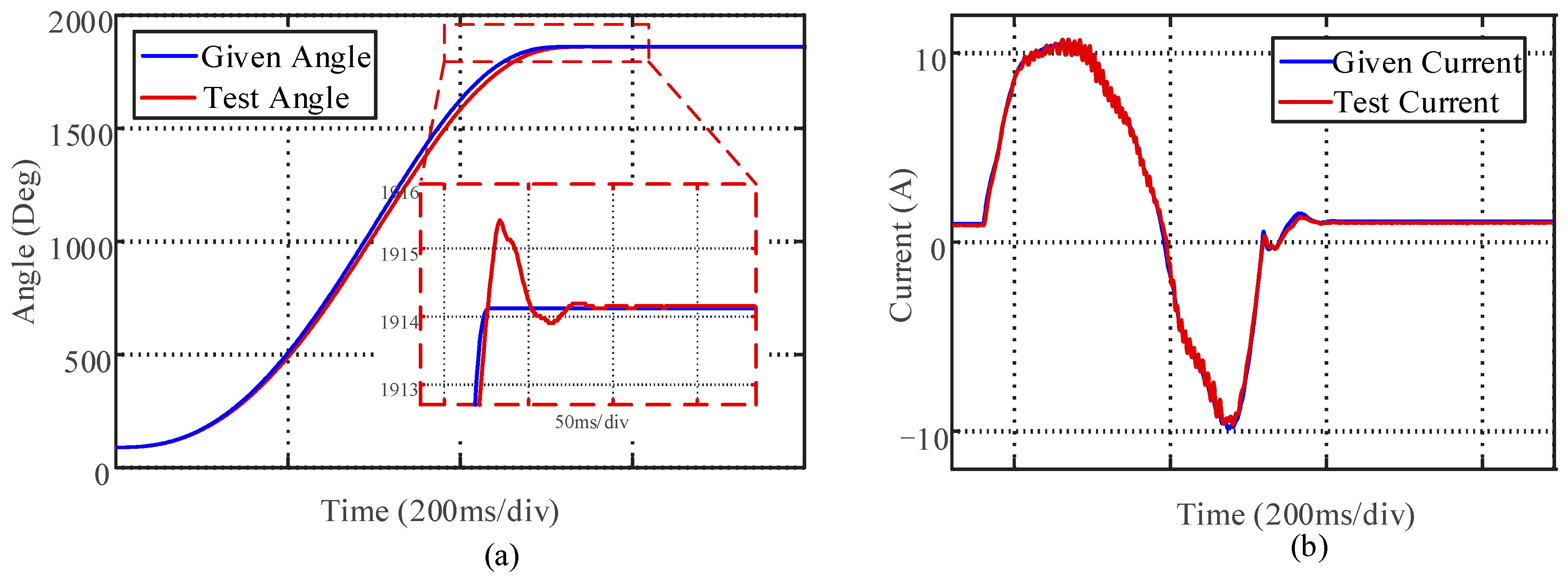
4.2. Trajectory Planning and Control Strategy Test Results

During the experiment, the target positioning angle is 1800°. A 1 Nm constant load torque is applied to the tested servo PMSM. The smooth and time-optimized Chebyshev seventh-degree polynomial trajectory adopted in this paper is compared with the traditional S-type trajectory.
In order to conduct a detailed comparative verification of the position servo control strategies proposed in this paper based on CPMT and non-cascaded ADRC, three different control strategies are simultaneously adopted for the positioning experiments: CPMT with ADRC; S-curve trajectory planning with ADRC; and CPMT with cascading PI. This is performed to fully compare and analyze the comprehensive influence of the trajectory planning and motor control methods on high-precision positioning. The three sets of experimental results are shown in Figure 7, Figure 8 and Figure 9.
As shown in Figure 7, in the servo control based on ADRC, due to the accurate following of the outer loop, the inner loop also shows a current curve consistent with the expected trajectory planning. The control strategy based on CPMT and ADRC can achieve good tracking of the given position during the positioning process. Due to the continuous impact of the trajectory, the motor current fluctuation is smaller and smoother. Meanwhile, the peak value of the current waveform is larger than that of the S-curve, effectively exerting the short-term overload capacity of PMSM.
It can be seen from Figure 8 that there is a certain error between the S-curve trajectory planning and the position tracking of the ADRC strategy, and the current waveform pulsation is relatively large. Mainly because the acceleration of the S-shaped curve is given in an approximately sloping manner, during the transition process, due to the discontinuous impact, the torque ripple and speed fluctuation of the servo drive system increase, resulting in a relatively large current ripple.
It can be seen from Figure 9 that although the current amplitude and the time to reach 1800 degrees of the CPMT and cascaded PI control strategy are basically the same as those in Figure 7, when the traditional PI cascaded control strategy is adopted, as the current increases, the following of the current closed loop shows a significant decrease due to the influence of electromagnetic saturation, and the current shows a relatively obvious following error and fluctuation. Electromagnetic saturation can lead to nonlinear changes in parameters such as inductance values, thereby reducing the stability of PI cascade control based on linear models for design and parameter tuning. Meanwhile, there was an obvious position overshoot at the positioning end, which caused changes in the current waveform at the positioning end and increased the steady-state positioning time.
The time required for CPMT and ADRC to reach steady-state positioning is 0.35 s, while S-shaped curves and ADRC and the CPMT and cascaded PI require 0.42 s and 0.4 s, respectively. The control method proposed in this paper can save more than 12.5% of the steady-state positioning time compared with the traditional method. During the experimental measurement process, although the sensor signal will cause certain measurement errors, the smoothness and positioning time of the three control strategies still have significant differences. It can be seen that the CPMT and the non-cascading ADRC servo controller constructed in this paper have excellent dynamic performance and more outstanding performance in terms of positioning time, the smoothness of the trajectory transition, and end jitter. On the one hand, it is because trajectory planning can ensure the impact continuity under overload operation. On the other hand, the motor control strategy based on ADRC can effectively suppress the trajectory tracking error caused by parameter changes under motor overload saturation.

5. Conclusions

A smooth and fast-response control strategy is very important for the high-precision position servo PMSM. In this paper, considering the multiple constraints of the short-term overload capacity of the servo PMSM, a jerk- and time-optimal trajectory planning method based on the seventh-degree Chebyshev polynomial is proposed, and a non-cascaded ADRC controller is used to achieve a better tracking effect. The main conclusions are as follows:
(1)
Based on the seventh-degree Chebyshev polynomial and the dynamic boundary conditions under the short-term overload of the PMSM, it is possible to take into account the fast-response performance while ensuring the continuous impact during the motion of the high-precision position servo system. Meanwhile, the FPSO algorithm can quickly solve the trajectory planning function and realize the online application of the impact-time-optimal trajectory planning.
(2)
By introducing the ADRC strategy, the problem of the decline in trajectory tracking performance of the servo PMSM system caused by internal and external interference errors is avoided. Directly applying CPMT to the design of the ADRC can fully take into account both smooth and fast-response performance. Through the prototype experiment test, the steady-state positioning time can be reduced to 0.35 s during the positioning process at 1800°. Compared with the traditional S-shaped trajectory curve or PI closed-loop control strategies, the positioning time can be reduced by more than 12.5%, and the smoothness of the trajectory has also been greatly improved.
(3)
The method proposed in this paper, through the integrated coordination of trajectory planning and control strategies, can achieve smooth and rapid response operation of high-precision position servo PMSM systems and can be widely applied in point-to-point position servo systems, such as in aerospace, industrial automation production lines, and multi-axis systems. Meanwhile, in future research, it is also necessary to take into account the computing power requirements of FPSO and the complexity of ADRC parameters, and continue to carry out research on the structure of FPSO algorithms, the adjustment and optimization of ADRC parameters, etc., in order to improve the applicability and practicability of the proposed method.

Author Contributions

Conceptualization, B.Y.; methodology, H.L.; software, T.Z.; validation, B.Y.; writing—original draft, B.Y.; writing—review and editing, B.Y., H.L., and X.X.; project administration, H.L. and X.X. All authors have read and agreed to the published version of the manuscript.

Funding

This work was supported in part by the National Key Research and Development Program of China under Grant No. 2024YFB3410600, in part by the National Natural Science Foundation of China under Grant No. 52207037, and in part by Graduate Student Research Innovation Project of Chongqing under Grant CYB22015.

Data Availability Statement

The data presented in this study are available upon request from the corresponding author. The data are not publicly available due to the confidentiality restrictions of this study.

Conflicts of Interest

The authors declare no conflicts of interest.

References

  1. Shi, S.; Dai, L.; Min, H.; Yang, J.; Li, S. Prescribed-Time Nonsingular Terminal Sliding Mode Control and Its Application in PMSM Servo Systems. IEEE Trans. Ind. Electron. 2025, 72, 3072–3081. [Google Scholar] [CrossRef]
  2. Cui, P.; Zheng, Z.; Fu, J.; Zhang, Q.; An, L. A Fault-Tolerant Control Method for a PMSM Servo Drive System with a Four-Leg Inverter. Electronics 2023, 12, 3857. [Google Scholar] [CrossRef]
  3. Lv, C.; Wang, B.; Chen, J.; Zhang, R.; Dong, H.; Wan, S. Research on a Torque Ripple Suppression Method of Fuzzy Active Disturbance Rejection Control for a Permanent Magnet Synchronous Motor. Electronics 2024, 13, 1280. [Google Scholar] [CrossRef]
  4. Wang, P.; Tang, J.; Lin, H.W.; Zhang, F.; Wang, C.; Wang, J.; Shi, L.; Meng, M.Q.-H. MINER-RRT*: A Hierarchical and Fast Trajectory Planning Framework in 3D Cluttered Environments. IEEE Trans. Autom. Sci. Eng. 2025, 22, 10973–10985. [Google Scholar] [CrossRef]
  5. Chen, Z.; Helian, B.; Zhou, Y.; Geimer, M. An Integrated Trajectory Planning and Motion Control Strategy of a Variable Rotational Speed Pump-Controlled Electro-Hydraulic Actuator. IEEE/ASME Trans. Mechatron. 2023, 28, 588–597. [Google Scholar] [CrossRef]
  6. Wang, M.; Xiao, J.; Zhao, W.; Liu, H. A Real-Time Trajectory Generator With 3rd-Order Constraints Satisfaction Through Velocity Mode Evolution. IEEE Trans. Ind. Electron. 2025, 72, 6205–6214. [Google Scholar] [CrossRef]
  7. Bai, Y.; Chen, X.; Sun, H.; Yang, Z. Time-Optimal Freeform S-Curve Profile Under Positioning Error and Robustness Constraints. IEEE/ASME Trans. Mechatron. 2018, 23, 1993–2003. [Google Scholar] [CrossRef]
  8. Biagiotti, L.; Melchiorri, C. Optimization of Generalized S-Curve Trajectories for Residual Vibration Suppression and Compliance With Kinematic Bounds. IEEE/ASME Trans. Mechatron. 2021, 26, 2724–2734. [Google Scholar] [CrossRef]
  9. Fang, S.; Cao, J.; Zhang, Z.; Zhang, Q.; Cheng, W. Study on High-Speed and Smooth Transfer of Robot Motion Trajectory Based on Modified S-Shaped Acceleration/Deceleration Algorithm. IEEE Access 2020, 8, 199747–199758. [Google Scholar] [CrossRef]
  10. Su, T.; Cheng, L.; Wang, Y.; Liang, X.; Zheng, J.; Zhang, H. Time-Optimal Trajectory Planning for Delta Robot Based on Quintic Pythagorean-Hodograph Curves. IEEE Access 2018, 6, 28530–28539. [Google Scholar] [CrossRef]
  11. Huang, M.S.; Hsu, Y.L.; Fung, R.F. Minimum-Energy Point-to-Point Trajectory Planning for a Motor-Toggle Servomechanism. IEEE/ASME Trans. Mechatron. 2012, 17, 337–344. [Google Scholar] [CrossRef]
  12. Deng, J.; Cui, X.; Tang, W.; Chen, W.; Sun, J. Research on Climbing Motion Planning of Inchworm Robot Based on Improved PSO. In Proceedings of the 2024 3rd International Conference on Service Robotics (ICoSR), Hangzhou, China, 26–28 July 2024; pp. 43–48. [Google Scholar]
  13. Wang, W.; Liu, C.; Liu, S.; Song, Z.; Zhao, H.; Dai, B. Current Harmonic Suppression for Permanent-Magnet Synchronous Motor Based on Chebyshev Filter and PI Controller. IEEE Trans. Magn. 2021, 57, 1–6. [Google Scholar] [CrossRef]
  14. He, X. Hybrid ADRC and PI Controller Design for Three-Phase Inverter with Nonlinear Loads. IEEE Access 2024, 12, 130857–130864. [Google Scholar] [CrossRef]
  15. Lixian, A.S.; Rahiman, W. A Compound Control for Hybrid Stepper Motor Based on PI and Sliding Mode Control. IEEE Access 2024, 12, 163536–163550. [Google Scholar] [CrossRef]
  16. Xia, C.; Ji, B.; Yan, Y. Smooth Speed Control for Low-Speed High-Torque Permanent-Magnet Synchronous Motor Using Proportional–Integral–Resonant Controller. IEEE Trans. Ind. Electron. 2015, 62, 2123–2134. [Google Scholar] [CrossRef]
  17. Mohamed, M.; Alaas, Z.M.; Al Faiya, B.; Hegazy, H.Y.; Mohamed, W.I.; Abdelwahab, S.A.M. Performance Improvement of Grid-Connected PV-Wind Hybrid Systems Using Adaptive Neuro-Fuzzy Inference System and Fuzzy FOPID Advanced Control With OPAL-RT. IEEE Access 2025, 13, 55996–56020. [Google Scholar] [CrossRef]
  18. Tarkhani, R.; Krim, S.; Mansouri, M.; Mimouni, M.F. Robust Current Sensor Fault-Tolerant Controller Using Third Order Super-Twisting Sliding Mode Observer and Controller for Induction Motors. IEEE Access 2025, 13, 52841–52862. [Google Scholar] [CrossRef]
  19. Yin, Y.; Liu, L.; Vazquez, S.; Xu, R.; Dong, Z.; Liu, J.; Leon, J.I.; Wu, L.; Franquelo, L.G. Disturbance and Uncertainty Attenuation for Speed Regulation of PMSM Servo System Using Adaptive Optimal Control Strategy. IEEE Trans. Transp. Electrif. 2023, 9, 3410–3420. [Google Scholar] [CrossRef]
  20. Tian, S.; Liu, K.-Z.; Zhang, M.; Lu, C.; Wu, M.; She, J. Improved Equivalent-Input-Disturbance Method for Nonlinear Repetitive-Control Systems: Integration With High-Order Sliding-Mode Control. IEEE/ASME Trans. Mechatron. 2025, 30, 692–702. [Google Scholar] [CrossRef]
  21. Liu, Z.-H.; Nie, J.; Wei, H.-L.; Chen, L.; Li, X.-H.; Lv, M.-Y. Switched PI Control Based MRAS for Sensorless Control of PMSM Drives Using Fuzzy-Logic-Controller. IEEE Open J. Power Electron. 2022, 3, 368–381. [Google Scholar] [CrossRef]
  22. Nguyen, T.H.; Nguyen, T.T.; Nguyen, V.Q.; Le, K.M.; Tran, H.N.; Jeon, J.W. An Adaptive Sliding-Mode Controller with a Modified Reduced-Order Proportional Integral Observer for Speed Regulation of a Permanent Magnet Synchronous Motor. IEEE Trans. Ind. Electron. 2022, 69, 7181–7191. [Google Scholar] [CrossRef]
  23. Fang, Q.; Zhou, Y.; Ma, S.; Zhang, C.; Wang, Y.; Huangfu, H. Electromechanical Actuator Servo Control Technology Based on Active Disturbance Rejection Control. Electronics 2023, 12, 1934. [Google Scholar] [CrossRef]
  24. Liu, G.; Fang, L.; Liu, Z.; Chen, Q.; Zhang, J. Active Disturbance Rejection Control of a Magnetic Screw Motor for High Tracking Performance. IEEE Trans. Power Electron. 2022, 37, 9641–9651. [Google Scholar] [CrossRef]
  25. Zhu, M.; Wu, Y. ChevOpt: Continuous-Time State Estimation by Chebyshev Polynomial Optimization. IEEE Trans. Signal Process. 2022, 70, 3136–3147. [Google Scholar] [CrossRef]
  26. NChen, N.; Yang, S.; An, S. A New Hybrid Algorithm Based on PSO and Fireworks Algorithm for Optimal Design of Metasurface Absorber in RF Energy Harvesting. IEEE Trans. Magn. 2025, 61, 1–4. [Google Scholar]
Figure 1. The comparison between trapezoidal and S-curve and 7th-order Chebyshev polynomial.
Electronics 14 02062 g001
Figure 2. Fast particle swarm convergence process.
Electronics 14 02062 g002
Figure 3. Third-order ESO and fal function block diagram. (a) Third-order ESO structural block diagram. (b) The fal function schematic diagram.
Electronics 14 02062 g003
Figure 4. Second-order ADRC servo control block diagram.
Electronics 14 02062 g004
Figure 5. Comparison of simulation results of PI closed-loop control strategy and proposed strategy under same positioning angel. (a) Mechanical angle of PI strategy; (b) mechanical angle of proposed strategy; (c) angular velocity of PI strategy; (d) angular velocity of proposed strategy; (e) current of PI strategy; and (f) current of proposed strategy.
Electronics 14 02062 g005
Figure 6. The experimental hardware platform.
Electronics 14 02062 g006
Figure 7. Experimental results of CPMT with ADRC process. (a) Current of test and given; (b) angle of test and given.
Electronics 14 02062 g007
Figure 8. Experimental results of S-curve trajectory planning with ADRC process. (a) Current of test and given; (b) angle of test and given.
Electronics 14 02062 g008
Figure 9. Experimental results of CPMT with cascade PI control process. (a) Current of test and given; (b) angle of test and given.
Electronics 14 02062 g009
Table 1. Main parameters of servo PMSM.
ParameterValue
Armature resistance (Ω)1.92
D-axis inductance (mH)8.5
Q-axis inductance (mH)11.7
Magnet flux linkage (Wb)0.036
Pole pairs4
Rated torque (Nm)3
Peak torque (Nm)6
Output power (W)750
Disclaimer/Publisher’s Note: The statements, opinions and data contained in all publications are solely those of the individual author(s) and contributor(s) and not of MDPI and/or the editor(s). MDPI and/or the editor(s) disclaim responsibility for any injury to people or property resulting from any ideas, methods, instructions or products referred to in the content.

