Article

Physical Layer Authentication Exploiting Antenna Mutual Coupling Effects in mmWave Systems

1
Portland Institute, Nanjing University of Posts and Telecommunications, Nanjing 210023, China
2
School of Computer Science, Nanjing University of Posts and Telecommunications, Nanjing 210023, China
*
Author to whom correspondence should be addressed.
Electronics 2025, 14(10), 2055; https://doi.org/10.3390/electronics14102055
Submission received: 21 April 2025 / Revised: 11 May 2025 / Accepted: 13 May 2025 / Published: 19 May 2025

Abstract

:
Impersonation attacks pose a significant threat to millimeter wave (mmWave) wireless systems due to the unique characteristics (e.g., highly directional beams) of mmWave communications. To this end, this paper proposes a novel physical layer authentication (PLA) scheme that leverages the antenna array-specific mutual coupling (MC) feature to validate the identity of the transmitter. In particular, we first demonstrate the authentication feasibility of the MC feature by modeling its amplitude and phase characteristics using generalized Gaussian and Laplace distributions, respectively. Then, based on the amplitude and phase of the MC feature, we design a kernel-based authentication scheme to further improve device distinguishability in mmWave systems. Moreover, we provide analytical expressions of the false alarm and detection probabilities, enabling a theoretical characterization of the proposed authentication scheme performance. Finally, numerical results are provided to verify the reliability and effectiveness of the proposed authentication scheme under various settings. The results indicate that the proposed scheme can provide performance gain compared to the single-dimensional feature-based schemes under different signal–noise ratio scenarios.

1. Introduction

Due to the bandwidth limitations of conventional wireless technologies, addressing the high data rate demands of fifth-generation (5G) wireless communications requires the adoption of novel solutions. Millimeter-wave (mmWave) communication, with its broad bandwidth range from 30–300 GHz and significantly enhanced data rates, is poised to play a crucial role in 5G network designs [1]. Such a technology can provide several advantages, such as narrow antenna beams [2], a wide transmission spectrum [3], low transmission latency, and the ability to achieve much higher data rates with comparable coverage and thus support the growing network demands of the Internet of Everything (IoE) [4] and vehicle-to-everything (V2X) [5] applications.
Despite the promising capabilities of mmWave communication systems, they are inherently vulnerable to identity-based impersonation attacks, primarily due to their key characteristics such as highly directional beamforming, limited coverage, and the potential for beam misalignment [6]. These vulnerabilities enable adversaries to impersonate legitimate devices or users, thereby gaining unauthorized access, disrupting communication, or engaging in malicious activities [7]. The impact of such attacks is particularly critical in several critical applications like autonomous driving and industrial automation, where the integrity of communication is paramount [8]. Consequently, robust authentication mechanisms are essential to establish secure communications and prevent unauthorized access for the concerned mmWave systems.
Cryptographic-based authentication has been the primary method for securing wireless communication systems [9,10]. It ensures security through key management and complicated mathematical computation. However, the management and distribution of these keys present significant challenges in the resource-constrained and dynamic mmWave systems [11]. Recently, physical layer authentication (PLA) has gained attention as a complementary solution. Due to the low communication overhead and enhanced system compatibility, it offers additional security without relying solely on cryptographic techniques [12,13]. The main principle of PLA is that it exploits unique channel features or hardware characteristics to construct and authenticate the identities of devices or users, which can typically be divided into two types: channel-based approaches [14,15,16,17,18,19] and hardware imperfection-based approaches [20,21,22,23,24].
Channel-based authentication primarily leverages the spatial variability in uncorrelated wireless channels across distinct geographical areas to achieve identification of wireless devices or users. For example, the authors in [14] leverage the sparsity of mmWave channels for user identification. Xiao et al. propose a method to detect Sybil attacks by exploiting the spatial variability in channel frequency responses, making it suitable for both wide-band and narrow-band systems [15]. The authors in [16] introduce an end-to-end physical layer authentication scheme for dual-hop wireless networks, utilizing location-specific features of channel amplitude and delay intervals, while incorporating artificial jamming to counter impersonation and replay attacks. Ferrante et al. focus on channel estimation-based authentication in Rayleigh fading channels, deriving an outer bound for the error region and optimizing attack strategies to minimize authentication errors [17]. Additionally, Wang et al. exploit the sparsity of mmWave channels to detect pilot contamination attacks under both static and dynamic environments [18]. While channel-based authentication is effective in mitigating unauthorized access, it primarily verifies the location or spatial signature of the transmitter rather than the identity of the device itself [19]. This dependence on spatial characteristics creates difficulties in situations where devices exhibit high mobility or experience frequent changes in location.
Hardware impairment-based authentication presents a highly effective and efficient method for bolstering security in mmWave communication systems. By exploiting the unique hardware characteristics of devices, this approach provides strong resistance to spoofing, requires minimal overhead, and adapts seamlessly to dynamic environments, offering enhanced security and making it a preferable choice for safeguarding mmWave networks from various security threats [20]. Zhao et al. propose an authentication scheme based on physical-layer phase noise fingerprints, combining phase noise and RF fingerprints to provide robust, low-computation security in emerging networks [21]. Polak et al. focus on exploiting phase noise to uniquely identify wireless devices [22]. Maeng et al. develop a power allocation strategy for fingerprint-based authentication in mmWave drone networks, optimizing both secrecy and achievable rate to strengthen security [23]. Shi et al. demonstrate that multi-input multi-output (MIMO) technology can improve the accuracy and stability of device identification by using multiple transmitters to enhance feature extraction [24].
It is worth noting that the aforementioned studies signify significant progress in the design of authentication solutions in mmWave systems. However, there are still several aspects for consideration to further motivate the development of PLA in mmWave systems. First, most existing hardware impairment-based PLA schemes mainly utilize hardware imperfections in the radio frequency chain (such as phase noise, carrier frequency offset, and I/Q imbalance), while ignoring hardware features such as mutual coupling (MC) effects that exist in massive MIMO antenna arrays. Recent research in [25] has also shown that MC is an inherent impairment in antenna arrays resulting from manufacturing tolerances and environmental factors. This effect is strongly influenced by the configuration of the antenna array and exhibits greater robustness to environmental changes, thus providing novel insights for the design of the PLA scheme. Second, existing authentication schemes often rely solely on the single-dimensional physical layer features of mmWave communication systems, which limits their performance due to the low distinguishability of these features. Finally, existing works primarily rely on the machine-learning approach, and the statistical performance evaluation of the authentication schemes remains an open issue.
Based on the above observations, we utilize the amplitude and phase of MC feature to design a kernel-based authentication scheme to determine the origin of the current received signals. Moreover, the analytical expressions of the authentication performance metrics, like detection and false alarm probabilities, are also derived to conduct the theoretical performance analysis. The main contributions of this paper are as follows:
  • To demonstrate the authentication feasibility of the MC feature, we first utilize the generalized Gaussian and Laplace distributions to precisely characterize the statistical model of amplitude and phase of MC, respectively.
  • To further enhance the device distinguishability, we leverage two unique hardware-specific fingerprints in terms of the amplitude and phase of MC to design a kernel-based identity authentication scheme tailored for the mmWave communication systems.
  • Based on the knowledge of statistical signal processing and hypothesis testing, we analytically derive expressions for the false alarm and detection probabilities, providing a theoretical characterization of the authentication performance of the proposed authentication scheme.
  • Finally, we resort to a series of experiments to verify the reliability, effectiveness of the proposed authentication scheme under various settings. The results also validate the correctness of the proposed theoretical performance metrics and demonstrate the satisfactory detection performance even in the low signal–noise ratio scenario.
While the proposed scheme demonstrates strong potential in exploiting MC features for authentication, it is important to acknowledge several practical considerations that may affect its robustness. For instance, variations in antenna configuration (e.g., element spacing or orientation), operating frequency, or transmit power can alter the electromagnetic environment and, consequently, the MC characteristics. Such changes may lead to mismatches between stored fingerprints and real-time measurements, potentially degrading authentication accuracy. Therefore, additional calibration mechanisms or adaptive re-learning schemes may be required in dynamic or reconfigurable deployment scenarios. These aspects will be considered in future extensions of this work.
Notation: ( · ) * , ( · ) T , and ( · ) H denote conjugate, transpose, and conjugate transpose operators, respectively. C M × N represents the set of complex-valued M × N matrices. A circularly symmetric complex Gaussian random vector x with zero mean and covariance matrix C can be denoted by x N ( 0 , C ) . E { · } represents the expectation operator. ≜ represents definitions. I n ( · ) is the nth order modified Bessel function of the first kind. Γ ( · ) is the Gamma function.

2. Problem Formulation and System Model

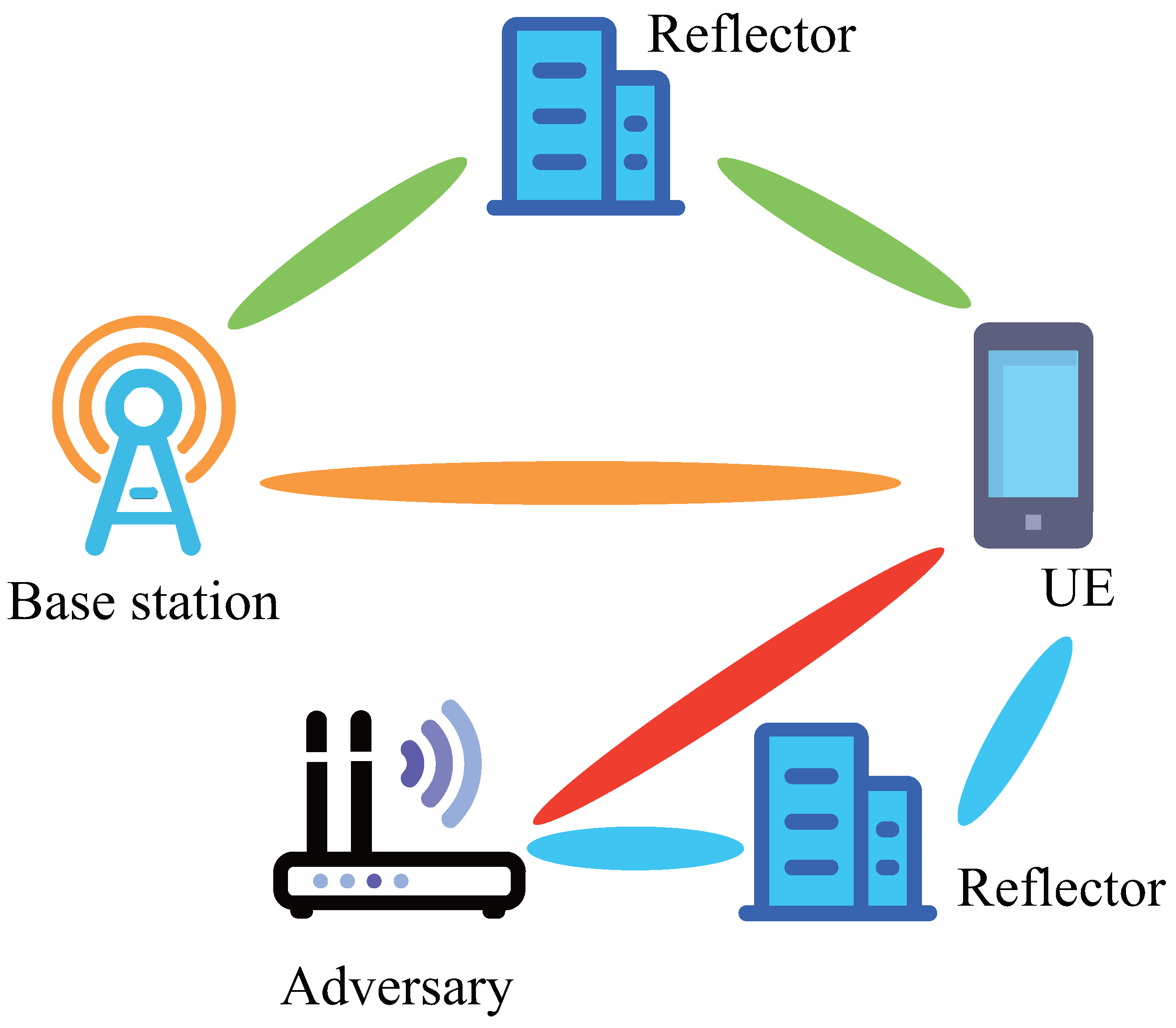
2.1. Problem Formulation

As shown in Figure 1, we consider an mmWave wireless communication system that includes a legitimate base station (Alice), a potential spoofing attacker (Eve), and a single-antenna user equipment (UE). The UE aims to receive messages from the authentic base station, which is equipped with an M-antenna uniform linear array (ULA) over a downlink communication. A quasi-omni beam pattern is formed at the UE side to ensure signal reception. Eve attempts to impersonate the legitimate base station by using an impersonated identity. To protect against such impersonation, the UE utilizes unique hardware-dependent mutual coupling (MC) features to authenticate the identity of the received signal frame.

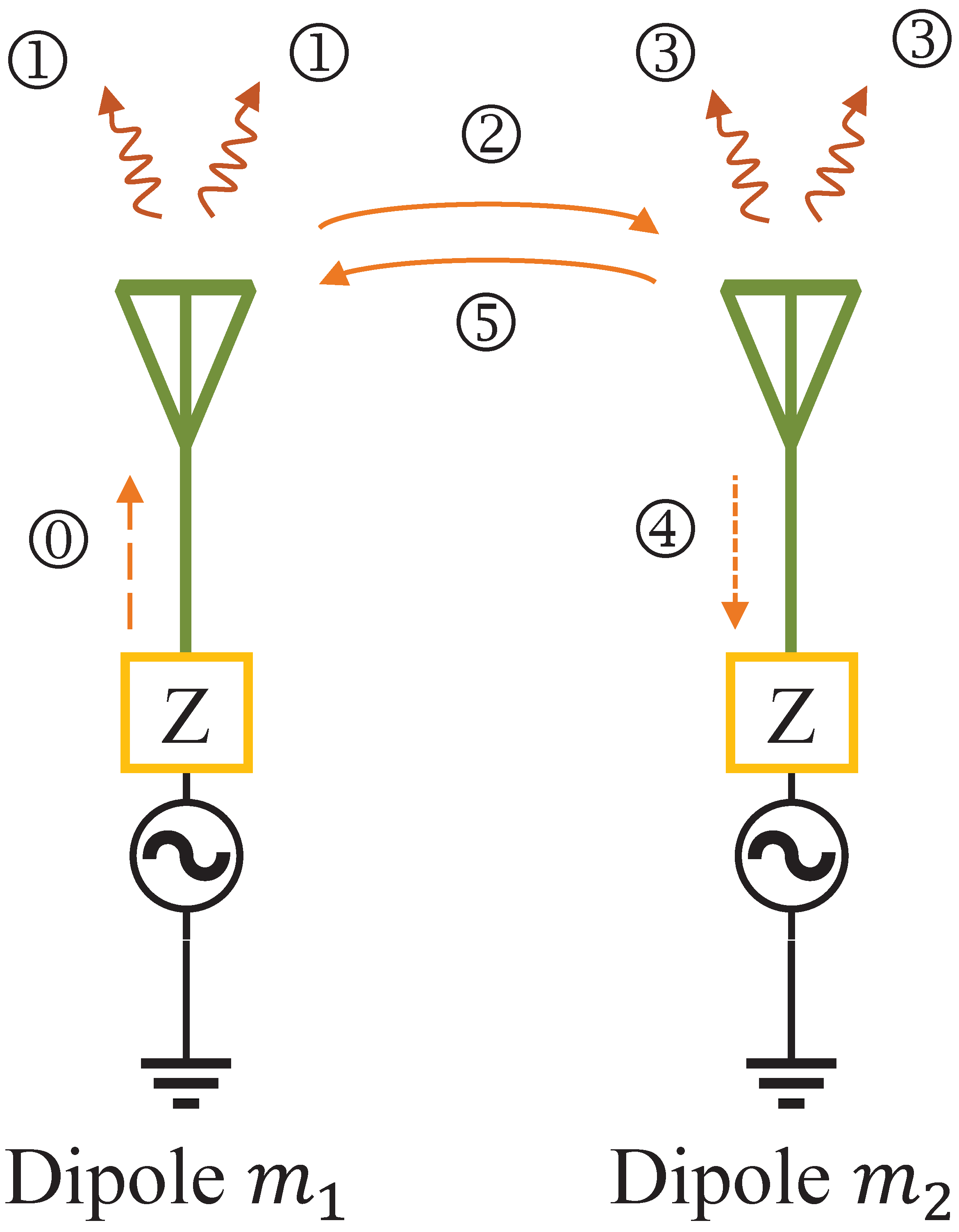
2.2. Antenna MC Model

In antenna array applications, MC can indeed introduce significant errors that affect the performance of the system. MC refers to the interaction between elements of an antenna array, where the signal received or transmitted by one antenna element affects the signals in other nearby elements. This can distort the signals, degrade the array’s radiation pattern, and impact the accuracy of signal-processing algorithms. MC effects are significantly influenced by factors such as antenna polarization, geometry design, and manufacturing materials. These factors create unique electromagnetic interactions between antenna elements, which can be exploited for various applications, including PHY-layer authentication.
The geometry of an antenna array is a fundamental factor influencing MC parameters. It directly impacts the electromagnetic interactions between elements, determining the magnitude and phase of the coupling coefficients. We first consider coupling in the transmitting mode in a uniform linear array (ULA). Because of space constraint, the antenna dipoles are closely positioned on in a uniform linear array ULA. When one element radiates, a portion of its energy is intercepted by neighboring elements. We take the transmitting mode as an example to illustrate the basic principle of MC effect generation in an antenna array. More specifically, without loss of generality, two dipole m 1 and m 2 of a ULA are positioned relative to each other as illustrated in Figure 2. When a signal source is connected to dipole m 1 , the energy produced will propagate towards the antenna designated as ⓪, subsequently radiating into space ① and toward the m 2 antenna ②. The energy impinging upon m 2 antenna induces currents that tend to reradiate a portion of the energy ③, while facilitating the transmission of the remainder toward m 2 generator ④. A portion of the rescattered energy ③ has the potential to be redirected toward antenna m 1 ⑤. This process may persist indefinitely. A similar procedure would ensue if antenna dipole m 2 was activated and antenna dipole m 1 served as the parasitic element. When both antenna dipoles are simultaneously activated, the resulting radiated and rescattered fields from each antenna must be combined vectorially to determine the total field at any given observation point. Consequently, the overall contribution to the far-field pattern of a specific element within the array is influenced not only by the excitation provided by its own generator (termed direct excitation) but also by the cumulative parasitic excitation. This parasitic excitation is contingent upon the couplings from and the excitation levels of the other generators [26]. This coupling effect is generally represented as a modification in the apparent driving impedance of the components, a phenomenon commonly termed mutual impedance variation.
By applying the principles of fundamental electromagnetics and circuit theory [26], the coupling matrix C T of the transmit antenna array can be modeled in a standard way as
C T = ( Z A + Z T ) ( Z + Z T I ) 1 ,
where Z A , Z T and Z C M × M are the load impedance, antenna impedance, and the mutual impedance matrix, respectively. Z is the mutual impedance matrix given by
Z = Z A + Z T z 1 , 2 z 1 , M z 2 , 1 Z A + Z T 0 z M , 1 z M , 2 Z A + Z T ,
where z m 1 , m 2 is the mutual impedance between the m 1 th and m 2 th antenna elements and is a complex value that is a function of the distance antenna elements. In the absence of MC, the matrix Z presented in (2) is characterized as diagonal. However, when mutual coupling occurs between the antenna elements, nonzero elements emerge in the off-diagonal positions. Figure 3 demonstrates the plot of the of the normalized impedance matrix elements for a ULA of 20 dipoles spaced λ / 2 apart with terminating impedance Z A = Z T . We can see that the coupling between adjacent elements remains relatively uniform throughout the array. Furthermore, the strength of the coupling diminishes significantly as one moves further from the diagonal. For a ULA, Z is a symmetric Toeplitz matrix and thus the coupling matrix C T C M × M of the antenna array can be expressed as banded symmetric Toeplitz matrices [27,28]. We assume that the number of nonzero mutual coupling coefficients of the transmit antenna array is M 1 and then C T could be rewritten as
C T = Toeplitz { c T , 0 ( M M 1 ) × 1 T } ,
where c T = [ c T , 1 , c T , 2 , , c T , M 1 ] T with c T , m = a T , m c e j ψ T , m c . a T , m c and ψ T , m c are the amplitude value and phase value of the mth mutual coupling coefficient, respectively, and 0 < | c T , M 1 | < < c T , 1 = 1 .
To apply mutual coupling features, we need to know statistical model for the factors c T , m . According to [29], the amplitude value and phase value of the mutual coupling amplitude coefficient a T , m c can be modeled as zero-mean generalized Gaussian random variables, that is,
f a T , m c ( x ) = β a 2 α a Γ 1 β a exp x α a β a ,
where α a and β a denote the scale and the shape parameters, respectively.
It is worth noting that ψ T , m p is the phase value of the MC coefficient c T , m and is based on [30] ψ T , m c , which can be modeled as a Laplacian distribution, i.e.,
f ψ T , m c ( x ) = 1 2 σ ψ 2 exp 2 σ ψ 2 | x | ,
where σ ψ 2 denotes the scale parameter. These parameters (i.e., α a , β a and σ ψ 2 ) are related to dipole distance and hardware impairments (such as the load impedance, antenna impedance, and the mutual impedance matrix). These parameters have inherent characteristics that can be used to distinguish the identity of the device. So far, we have provided the statistical models for C T and following a similar manner, the coupling matrix C R of the receiving antenna array has a similar expression form. We assume that the number of nonzero mutual coupling coefficients of the transmit antenna array is N 1 and then C R could be rewritten as
C R = Toeplitz { c R , 0 ( N N 1 ) × 1 T } .
It is worth noting that the assumption of identical ULA configurations with fixed inter-element spacing may not hold in adversarial settings. A well-equipped attacker may deliberately design antenna arrays to mimic the MC characteristics of a target device, especially after observing transmitted signals over time. In such cases, the uniqueness and stability of MC fingerprints could be compromised. Therefore, to ensure authentication robustness in the presence of adaptive adversaries, the proposed method could be extended by incorporating additional features such as time-varying channel statistics, gain/phase distortion fingerprints, or employing a dynamic challenge-response mechanism. These considerations form part of our planned future work.

2.3. Signal Model

Consider a massive MIMO communication system with a transmitter equipped with an array of M transmit antennas and a receiver with an array of N receive antennas, and a potential adversary with a transmit array of M elements. The potential adversary attempts to impersonate as the legitimate transmitter for inserting harmful information into the concerned communication system. All of them are equipped with ULAs with interelement spacing being half-wavelength. Suppose that M orthogonal signals are transmitted by M antennas at time t, i.e., s ( t ) = [ s 1 ( t ) , , s M ( t ) ] T , where s m ( t ) is the mth baseband signal and E { | s m ( t ) | 2 } = 1 and E { | s m ( t ) s n ( t ) | } = 0 (for m n ). Let d T and d R be the distance between two adjacent antennas in the transmitter and receiver, respectively (referred to as the separation distance). The extended Saleh-Valenzuela (SV) model in [31] is employed to characterize the concerned channel. Let θ l and ϕ l be the direction of departure (DoD) and direction of arrival (DoA) for the lth propagation path, respectively. Then, The steering vectors of the transmitter and receiver are expressed, respectively, by
a T ( θ l ) = [ 1 , e j 2 π d T λ sin θ l , . . . , e j 2 π ( M 1 ) d T λ sin θ l ] T ,
a R ( ϕ l ) = [ 1 , e j 2 π d R λ sin ϕ l , . . . , e j 2 π ( N 1 ) d R λ sin ϕ l ] T .
We consider narrow-band quasi-static fading channels and there are L propagation paths between the transmitter and receiver. This study investigates the uplink communication in a single transmission frame that is composed of K signal blocks. It is assumed that the channels remain unchanged in each block. The value of K is an arbitrary integer that is determined by the channel coherence time. If the transmitter UE transmits the M × 1 signal vector s ( t ) at time t for the kth block, the signal received at the BS is given by
y ( t , k ) = l = 1 L a l ( k ) [ C R a R ( ϕ l ) ] [ C T a T ( θ l ) ] T s ( t ) + n ( t , k ) = [ C R A R ( ϕ ) ] diag { a ( k ) } [ C T A T ( θ ) ] T s ( t ) + n ( t , k ) ,
where A T ( θ ) = [ a T ( θ l ) , , a T ( θ L ) ] and A R ( ϕ ) = [ a R ( ϕ l ) , , a R ( ϕ L ) ] ; n ( t , k ) is a noise vector with zero-mean white Gaussian distribution with variance σ n 2 I N ; a ( k ) = [ a 1 ( k ) , , a L ( k ) ] T with a l ( k ) being the channel gain along the lth path.
The objective of this paper is develop a novel authentication scheme utilizing the MC feature to resist against the identity-based impersonation attack. One can see from (9) that we need to estimate MC in C T based on the received observation signal vector.

3. Proposed Kernel-Based Authentication Scheme

3.1. Estimate MC

Using the orthogonality property of transmitted signals (a matched filter method) and performing the vectorization operation yields the M N × 1 virtual data vector as
y ( k ) = [ C T C R ] [ A T A R ] a ( k ) + n ( k ) = C A ( θ , ϕ ) a ( k ) + n ( k ) ,
where A ( θ , ϕ ) = [ a ( θ 1 , ϕ 1 ) , , a ( θ L , ϕ L ) ] denotes the ideal steering matrix of the virtual array with a ( θ l , ϕ l ) = a T ( θ l ) a R ( ϕ l ) ; n ( k ) CN ( 0 , σ n 2 I M N ) denotes the noise term; and the MC matrix C C M N × M N is expressed by
C = C T C R = Toeplitz { C R , c T , 1 C R , , c T , M 1 C R , 0 N × N , , 0 N × N } .
Collecting K signal blocks forms the following expression as
Y = C A ( θ , ϕ ) H + N ,
where Y = [ y ( 1 ) , , y ( K ) ] , H = [ a ( 1 ) , , a ( K ) ] and N = [ n ( 1 ) , , n ( K ) ] . It is noticed that the received signal model in (12) is not limited to be within a half wavelength separation distance and hence this can be readily extended for any antenna element spacing. Here, we consider that the transmit antenna array has the identical number of nonzero mutual coupling coefficients of the receive array, i.e., M 1 = N 1 . To determine the angles and mutual coupling without ambiguity, it may be inferred from [32] that the necessary condition of M 1 = N 1 is M 1 = N 1 min { ( L ( M N L ) 2 L ) / 2 ,   M / 2 ,   N / 2 } .
MC compensation: In this subsection, the goal is to extract MC. It is noticed that we first need to jointly estimate DoD and DoA with unknown MC. To facilitate the joint accurate DoD and DoA estimation, it is necessary to implement MC compensation. In particular, the first and last M 1 ( N 1 ) transmit (receiving) antenna elements are designated as auxiliary elements. The remaining elements are renumbered from 1 to M 2 = M 2 M 1 and from 1 to N 2 = N 2 N 1 , respectively. We denote by Y ¯ the M 2 N 2 × K virtual received data matrix obtained from the M 2 + N 2 non-auxiliary elements. To mitigate the effect of mutual coupling, the data from the 2 ( M 1 + N 1 ) auxiliary elements is discarded, and Y ¯ is directly used for angle estimation. More specifically, define the matrices Q T [ 0 M 2 × M 1 , I M 2 , 0 M 2 × M 1 ] and Q R [ 0 N 2 × N 1 , I N 2 , 0 N 2 × N 1 ] and then the received data Y ¯ can be obtained by left multiplying Q T Q R on both sides of Y in (12) as
Y ¯ = ( Q T Q R ) Y = [ Q T C T Q R C R ] A ( θ , ϕ ) H + ( Q T Q R ) N = C ¯ A ( θ , ϕ ) H + N ¯ ,
where C ¯ = Q T C T Q R C T C M 2 N 2 × M N is an equivalent composite MC matrix, and N ¯ C M 2 N 2 × K is a new noise matrix. It is easy to calculate the covariance matrix of Y ¯ as
R Y ¯ = E { Y ¯ Y ¯ H } = C ¯ A ( θ , ϕ ) R H A H ( θ , ϕ ) C ¯ H + σ n 2 I M 2 N 2 ,
where R H = E { H H H } . Performing the eigendecomposition on the M 2 N 2 × M 2 N 2 covariance matrix R Y ¯ , then we have
R Y ¯ = E ¯ s Λ ¯ s E ¯ s H + E ¯ n Λ ¯ n E ¯ n H ,
where E ¯ s denotes the signal subspace consisting of the eigenvectors corresponding to the largest L eigenvalues and E ¯ n denotes the noise subspace containing the rest eigenvectors of R Y ¯ . It was proved in [32] that the subspace E ¯ s consisting of non-auxiliary components, is resistant to MC and can be directly utilized for accurately estimating the angles since the mutual coupling effect is compensated.
Angle estimation applying the complex matrix method: Here a complex matrix method is employed to estimate the DoD and DoA. Observing (13), we find that the subspace spanned by C ¯ A ( θ , ϕ ) is identical to the subspace spanned by the column eigenvectors in matrix E ¯ s . Then, it should have a unique nonsingular matrix Γ to satisfy
E ¯ s = C ¯ A ( θ , ϕ ) Y = A ¯ ( θ , ϕ ) Δ Y ,
where A ¯ ( θ , ϕ ) = [ a ¯ ( θ 1 , ϕ 1 ) , , a ¯ ( θ L , ϕ L ) ] and Δ = diag { Δ ( θ 1 , ϕ 1 ) , , Δ ( θ L , ϕ L ) } . Choosing different submatrices from E ¯ s constructs the shift invariance matrices of the transmit and receive arrays for angle estimation. Define Ψ T Y 1 Φ T Y and Ψ R Y 1 Φ R Y , where Φ T = diag { e j 2 π d T λ sin θ 1 , , e j 2 π d T λ sin θ L } and Φ R = diag { e j 2 π d R λ sin ϕ 1 , , e j 2 π d R λ sin ϕ L } are the shift invariance matrices of the transmit and receive arrays, respectively. Let D 0 = Y 1 I L Y . Based on Φ T and Φ R , a complex matrix denoted by G i ( i = T , R ) can be expressed as
G i = ( Ψ i + D 0 ) 1 ( Ψ i D 0 ) = Y 1 ( Φ i + I L ) 1 ( Φ i I L ) Y .
To simplify notation, let ω i , l = 2 π d i λ sin ϕ l and then the eigenvalues of G i are given by
( Φ i + I L ) 1 ( Φ i I L ) = diag j tan ω i , 1 2 , , j tan ω i , L 2 .
Combining Ψ T and Ψ R constructs a complex pairing matrix G T + G R , whose eigenvalues can be calculated as
( Φ T + I L ) 1 ( Φ T I L ) + j ( Φ R + I L ) 1 ( Φ R I L ) = diag tan ω R , 1 2 + j tan ω T , 1 2 , , tan ω R , L 2 + j tan ω T , L 2 .
One can see from (19) that the lth eigenvalue is uniquely associated with the parameters e j ω R , l and e j ω T , l , where the real and imaginary parts correspond to the real and imaginary parts of the eigenvalue, respectively. Hence, if we let λ l be the eigenvalue estimates of G T + G R , then the estimates of θ ^ l and ϕ ^ l for l = 1 , , L are expressed, respectively, as
θ ^ l = arcsin { λ d T π arctan [ Im ( λ l ) ] } , ϕ ^ l = arcsin { λ d R π arctan [ Re ( λ l ) ] } .
The DoD and DoA estimation includes two key steps: (1) decoupling operation; (2) complex matrix based on angle estimation.
The decoupling operation is performed by setting the auxiliary elements. Secondly, the angles are estimated using the complex matrix method.
Mutual coupling coefficients estimation: So far we have obtained DoD and DoA estimation and then we can perform MC estimation via the received data of the full virtual array.
To this end, we first calculate the M N × M N sample covariance matrix of Y in (12) as R Y = 1 K k = 1 K y k y k H , and then performing the eigendecomposition on R Y as
R Y = E s Λ s E s H + E n Λ n E n H ,
where E s and E n are the signal subspace and noise subspace, respectively. To facilitate MC estimate, we resort to the following lemma regarding the MC matrix.
Lemma 1.
For a complex symmetric Toeplitz matrix X = T o e p l i t z { x } C K × K and a complex vector z , we have the following relationship
X z = D x ,
where D = D 1 + D 2 with the ith ( i = 1 , , M ) row and the jth ( j = 0 , , K 1 ) column entries being
[ D 1 ] i , j = x i + j , 0 , i + j K 1 otherwise
[ D 2 ] i , j = x i j , 0 , i j 1 otherwise
Let δ l = [ C T a T ( θ l ) ] [ C R a R ( ϕ l ) ] and, based on Lemma 1 and (10), we have
δ l = [ D T ( θ l ) D R ( ϕ l ) ] c = D ( θ l , ϕ l ) c ,
where c c T c R . Now, we construct a cost function
J = l = 1 L | | E n H δ l | | 2 ,
and then the estimate of c can be expressed as
c ^ = arg min c l = 1 L | | E n H D ( θ ^ l , ϕ ^ l ) c | | 2 arg min c c H B c ,
where B = l = 1 L [ D H ( θ ^ l , ϕ ^ l ) E n H E n D ( θ ^ l , ϕ ^ l ) ] is postive-definite Hermitan matrix. Then, since c ( 1 ) = 1 , (27) becomes a constrained optimization problem and we can solve this optimization to extract c ^ . According to the structure of c c T c R , we have
c ^ T , m = c ^ ( m M 1 + 1 ) , m = 0 , . . . , M 1 .
Consider that there are K samples for c ^ T and construct an estimate matrix C ^ T = [ c ^ T , 1 , , c ^ T , K ] where c ^ T , k = [ c ^ T , 1 k , , c ^ T , M 1 k ] T . Performing vectorization and reforming the elements yields K M 1 estimates c ^ T , i = a ^ T , i e j Ψ ^ T , i for i = 1 , . . . , K M 1 . Due to the existence of the estimation error, the amplitude and phase of MC estimates c ^ T , i can be decomposed as
a ^ T , i = a T , i c + a T , i ϵ , i = 1 , . . . , K M 1 ,
Ψ ^ T , i = Ψ T , i c + Ψ T , i ϵ , i = 1 , . . . , K M 1 ,
where a T , i ϵ and Ψ T , i ϵ are the amplitude and phase component of the estimate error, respectively, and we have a T , i ϵ N ( 0 , σ a , ϵ 2 ) and Ψ T , i ϵ N ( 0 , σ Ψ , ϵ 2 ) .
Based on (29) and (30), we can calculate the scale parameter α a and the shape parameter β a associated with the amplitude value, and the scale parameter σ ψ 2 associated with the phase value, and these parameters govern the mean and variance in the normal distribution for the kernel-based test statistics (which will be introduced in Section 3.2).
MC is not isolated in practice and often coexists with other RF impairments such as mutual impedance, antenna mismatch, and multi-path interference. Although our compensation and subspace projection techniques are designed to mitigate these influences, their separation under hardware constraints remains challenging. Extending the model to jointly estimate and compensate for multiple types of hardware impairments will be explored.

3.2. Validation Decision

Given the knowledge that the adversary Eve has the ability to modify transmit signals or channels to compromise the authentication system, Bob employs a hypothesis test [33] to determine if the message was initiated by Alice. There are two hypotheses regarding Bob as
  • H 0 : the signal frame is from Alice,
    a ^ T , i = a T , i c + a T , i ϵ , i = 1 , . . . , K M 1 ,
    Ψ ^ T , i = Ψ T , i c + Ψ T , i ϵ , i = 1 , . . . , K M 1 ,
  • H 1 : the signal frame is not from Alice,
    a ^ T , i a T , i c + a T , i ϵ , i = 1 , . . . , K M 1 ,
    Ψ ^ T , i Ψ T , i c + Ψ T , i ϵ , i = 1 , . . . , K M 1 ,
Since the amplitude and phase of MC associated with the antenna array for the adversary Eve is different from that of Alice, thus the above two hypotheses can further formulated as
H 0 : a ^ T , i = a T , i c + a T , i ϵ , Ψ ^ T , i = Ψ T , i c + Ψ T , i ϵ ,
H 1 : a ^ T , i = a T , i c + a T , i ϵ + a T , i e , Ψ ^ T , i = Ψ T , i c + Ψ T , i ϵ + Ψ T , i e
where a T , i e and Ψ T , i e ( i = 1 , . . . , K M 1 ) are the amplitude and phase component of the nonzero offset (attack) data caused by inherent antenna characteristics of Eve, respectively, and a T , i e N ( 0 , σ a , e 2 ) and Ψ T , i e N ( 0 , σ Ψ , e 2 ) .
We adopt the kernelized energy detector proposed in [34] to perform the authentication decision, i.e.,
T = 1 N ( N 1 ) i = 1 N j = 1 , j i N Ω ( x i , x j ) H 0 H 1 γ ,
where Ω ( x i , x j ) is a nonlinear kernel function and N is the number of variables. The asymptotic distribution of the kernel-based test statistic in (36) can be determined according to the U-statistics theory in [35] (Chapter 5). In particular, when N is sufficiently large, the test statistic in (36) follows a normal distribution in both hypotheses as follows:
T N ( μ 0 , σ 0 2 ) , N ( μ 1 , σ 1 2 ) , under H 0 under H 1
where the mean μ and variance σ 2 for = 0 , 1 can be computed, respectively, as
μ = E X i , X j { Ω ( x i , x j ) } = 1 N ( N 1 ) i = 1 N j = 1 , j i N Ω ( x i , x j ) ,
σ 2 = 4 N E X i { ( E X j { Ω ( x i , x j ) } ) 2 [ E X j { Ω ( x i , x j ) } ] 2 = 4 N 1 N i = 1 N 1 N j = 1 N Ω ( x i , x j ) 2 μ k 2 .
Notably, gain and phase elements have different distribution, so we can employ the kernel-based test statistic in (36) to develop two different detectors exploiting amplitude and phase variables. Hence, based on (36), we have
T a = 1 K M 1 ( K M 1 1 ) i = 1 K M 1 j = 1 , j i K M 1 Ω ( a i , a j ) H 0 H 1 γ a ,
T Ψ = 1 K M 1 ( K M 1 1 ) i = 1 K M 1 j = 1 , j i K M 1 Ω ( Ψ i , Ψ j ) H 0 H 1 γ Ψ .
Based on the extracted MC and the corresponding statistics, we can perform an authentication decision by employing the kernel-based authentication decision. Now, we are ready to introduce our proposed authentication decision procedure in the wireless communication system from the practical perspective. There are two key stages: (1) the fine sensing stage; (2) the fast validation stage. In the fine sensing stage, amplitude (resp. phase) values for the MC estimates are utilized to calculate the asymptotic distribution of the corresponding kernel-based test statistic under the hypothesis H 0 , defined as a normal distribution with mean μ a , 0 (resp. μ Ψ , 0 ) and variance σ a , 0 2 (resp. σ Ψ , 0 2 ) to determine the amplitude decision threshold γ a (the phase decision threshold γ Ψ ). In the fast validation stage, the measured values of the kernel-based test statistic in (40) and (41) for the extracted MC in terms of the amplitude and phase values are compared with γ a and γ Ψ , respectively, to determine the origin of the current signal frame.
The uniqueness of MC-based fingerprints can be limited among devices that share identical antenna designs or manufacturing processes. A sophisticated adversary might replicate similar MC patterns using comparable hardware configurations, posing a spoofing risk. To address this, future enhancements may include combining MC features with other device-specific signatures (e.g., gain/phase distortions) or employing randomized challenge–response protocols to improve resilience against impersonation attacks.

4. Performance Analysis

In this section, we first derive the false alarm probability P f and detection probability P d for the proposed authentication scheme by applying the theory in [36], and calculate the two decision thresholds for a constant false alarm probability. Then, the mean value and the variance in the asymptotic distribution of the kernel-based test statistic are derived theoretically for the amplitude variable following the generalized Gaussian distribution, and the phase variable following Laplacian distribution scenarios.

4.1. Representation for P f and P d

Let P f , a and P f , Ψ be the false alarm probabilities exploiting the amplitude elements and phase in MC, respectively, and P d , a and P d , Ψ be the detection probabilities exploiting the amplitude elements and phase in MC, respectively. Based on the result for the asymptotic distribution of the kernel-based test statistic in (37)–(39), P f , x and P d , x for x = { a , Ψ } can be expressed, respectively, by
P f , x = 1 Q γ x μ x , 0 σ x , 0 2 ,
P d , x = 1 Q γ x μ x , 1 σ x , 1 2 .
To find the individual thresholds γ a and γ Ψ corresponding to the proposed authentication using amplitude decision and phase decisions, the Neyman–Pearson criterion is adopted as in [37], where P f , x in (42) is set to a constant in the range of [ 0.05 , 0.1 ] compatible with the authentication standards in [38,39]. Therefore, the threshold γ x is determined as
γ x = Q 1 ( 1 P f , x ) σ x , 0 2 + μ x , 0 , x = { a , Ψ } .
In this paper, we adopt the AND rule to make a final decision for identity validation. Thus, combining (42) and (43), P f and P d are written, respectively, as
P f = P f , a P f , Ψ = 1 Q γ a μ a , 0 σ a , 0 2 1 Q γ Ψ μ Ψ , 0 σ Ψ , 0 2 ,
P d = P d , a P d , Ψ = 1 Q γ a μ a , 1 σ a , 1 2 1 Q γ Ψ μ Ψ , 1 σ Ψ , 1 2 .

4.2. Representation for μ a , and σ a , 2

There are many bounded kernel functions such as Gaussian and Laplacian kernels, as listed in Table 1 [40], and in this paper we examine the bounded Gaussian kernel function for performance analysis and simulations of the kernel-based authentication scheme, as this kernel function is adopted in much of the relevant literature [40]. To express P f in (45) and P d in (46) for the proposed kernel-based authentication scheme jointly utilizing 2-dimension MC features in terms of amplitude and phase, it needs to derive the theoretical values of μ a , , μ Ψ , , σ a , 2 and σ Ψ , 2 in (38) and (39) corresponding to the considered amplitude and phase distributions.
We first consider μ a , and σ a , 2 . Under H 0 , the amplitude estimate of MC is viewed as a linear combination of the generalized Gaussian distributed random variable (true amplitude) and Gaussian distributed random variable (estimate error). Applying these considerations in (38), the mean value of the test statistics T a in (40) under H 0 is developed as (48) at the top of the next page, where ( a ) is obtained by employing integral of exponential functions in ([41] p. 108) to calculate E U i , U j { } and ( b ) is achieved by changing variables ( v i 2 ( 2 σ ϵ 2 + η 2 ) x and v j 2 ( 2 σ ϵ 2 + η 2 ) y ), and f ( x i 1 , y i 2 ) is written as
f ( x i 1 , y i 2 ) = exp 2 x i 1 y i 2 × exp 2 ( 2 σ ϵ 2 + η 2 ) | x i 1 | a β + | y i 2 | a β α a β a .
μ a , 0 = E X i , X j exp ( x i x j ) 2 2 η 2 E U i , U j , V i , V j exp ( u i u j ) 2 + ( v i v j ) 2 2 η 2 = E V i , V j exp ( v i v j ) 2 2 η 2 E U i , U j exp ( u i u j ) 2 + 2 ( u i u j ) ( v i v j ) 2 η 2 = ( a ) E V i , V j exp ( v i v j ) 2 2 η 2 η exp σ ϵ 2 ( v i v j ) 2 2 σ ϵ 2 η 2 + η 4 2 σ ϵ 2 + η 2 = ( b ) E X , Y 2 η 2 σ ϵ 2 + η 2 exp 2 x y x 2 y 2 η β a 2 2 σ ϵ 2 + η 2 2 α a 2 Γ 2 1 β a i 1 N 1 i 2 N 2 W i 1 W i 2 f ( x i 1 , y i 2 ) .
Based on μ a , 0 , the variance in the test statistics in (40) under H 0 is developed as (50), which is obtained by using variable changes ( v j ( σ ϵ 2 + η 2 ) y , and u j 2 σ ϵ 2 ( σ ϵ 2 + η 2 ) 3 σ ϵ 2 + η 2 z ), and f ( x i 1 , y i 3 , z i 4 ) is expressed by
f ( x i 1 , y i 3 , z i 4 ) = exp 4 σ ϵ 2 3 σ ϵ 2 + η 2 x i 1 z i 4 × exp ( 2 x i 1 y i 3 ) exp ( | x i 1 | 2 ( σ ϵ 2 + η 2 ) ) β a α a β a .
σ a , 0 2 = 4 K M 1 β a 3 η 2 ( σ ϵ 2 + η 2 ) 4 α a 3 Γ 3 1 β a π ( 3 σ ϵ 2 + η 2 ) i 1 N 1 i 2 N 2 W i 1 W i 2 i 3 N 3 i 4 N 4 W i 3 W i 4 f ( x i 1 , y i 3 , z i 4 ) f ( x i 2 , y i 3 , z i 4 ) × exp 2 σ ϵ 2 3 σ ϵ 2 + η 2 y i 3 z i 4 exp ( | y i 3 | σ ϵ 2 + η 2 ) β a α a β a μ a , 0 2 .
Similarly, we can derive the mean value μ a , 1 and the variance σ a , 1 2 in the test statistics T a in (40) under hypothesis H 1 . Since the offset data a T , i e and estimate error a T , i ϵ follow Gaussian distribution, we can obtain μ a , 1 and σ a , 1 2 by replacing σ ϵ 2 with σ ϵ 2 + σ e 2 in (48) and (50).
To obtain closed-form analytical expressions for μ a , and σ a , 2 , we consider the amplitude estimate samples, i.e., ( a ^ T , i , a ^ T , j ) follow real Gaussian distribution with zero mean and variance σ a ^ 2 where σ a ^ 2 is the summation in the amplitude and the estimate error variances under the hypothesis H 0 , that is, σ a ^ 2 = σ a 2 + σ ϵ 2 , while under the alternative hypothesis H 1 , σ a ^ 2 is the summation of the amplitude, the estimate error and offset data variances under the hypothesis H 1 , i.e., σ a ^ 2 = σ a 2 + σ ϵ 2 + σ e 2 . Exploiting the integral of exponential functions in [41] (p. 108), μ a , for = 0 , 1 is expressed as
μ a , = η 2 σ a ^ 2 + η 2 .
Following a similar procedure conducted in (52), the σ a , 2 defined in (39) for the two hypotheses is written as
σ a , 2 = 4 K M 1 η 2 3 σ a ^ 4 + 4 σ a ^ 2 η 2 + η 4 η 2 2 σ a ^ 2 + η 2 .

4.3. Representation for μ Ψ , and σ Ψ , 2

Now, we derive the mean value μ Ψ , and variance value of σ Ψ , 2 of the test statistics T Ψ in (41). Under H 0 , the distribution of the extracted phase samples will be a linear combination of Gaussian error random variable and Laplacian phase random variable in (5). Under this case, the mean value of the test statistics T Ψ under H 0 with the Laplacian phase assumption μ Ψ , 0 , is written by using the Laplacian distribution in ((48), (a)) as (53).
μ Ψ , 0 = η 2 π exp 2 σ Ψ , ϵ 2 + η 2 σ Ψ 2 σ Ψ 2 2 σ Ψ , ϵ 2 + η 2 π exp 2 σ Ψ , ϵ 2 + η 2 σ Ψ 2 + σ Ψ 2 2 σ Ψ , ϵ 2 + η 2 σ Ψ erfc 2 σ Ψ , ϵ 2 + η 2 σ Ψ .
Based on (39) and following a similar manner to that adopted in (53), the variance in the test statistics T Ψ in (41) with the Laplacian phase scenario for the hypothesis H 1 is obtained as (56), where f X ( x i ) is the PDF of the linear combination of Gaussian and Laplacian distributions defined as [42]
f X ( x i ) = 1 8 σ Ψ exp σ Ψ , ϵ 2 σ Ψ 2 exp 2 x i σ Ψ × efrc σ Ψ , ϵ σ Ψ x i 2 σ Ψ , ϵ + exp 2 x i σ Ψ efrc σ Ψ , ϵ σ Ψ + x i 2 σ Ψ , ϵ ,
and M ( x i ) is expressed, respectively, as
M ( x i ) = exp 2 x i σ Ψ erfc x i 2 ( σ Ψ , ϵ 2 + η 2 ) + ( σ Ψ , ϵ 2 + η 2 ) σ Ψ .
σ Ψ , 0 2 = η 2 π exp 2 ( σ Ψ , ϵ 2 + η 2 ) σ Ψ 2 K M 1 σ Ψ 2 M ( x i ) + M ( x i ) 2 f X ( x i ) d x i 4 μ Ψ , 0 2 K M 1 .
Substituting (54) and (55) into (56) and applying the approximation erfc ( x ) α e x 2 , the variance in the test statistics T Ψ in (41) with the Laplacian phase scenario for the hypothesis H 1 is determined as in (57), where D 1 D 6 are given in Appendix A.
σ Ψ , 0 2 = η 2 π exp ( 3 σ Ψ , ϵ 2 + 2 η 2 ) σ Ψ 2 K M 1 8 σ Ψ 3 π ( σ Ψ , ϵ 2 + η 2 ) exp 3 ( σ Ψ , ϵ 2 + η 2 ) 2 σ Ψ 2 D 6 2 + ( D 4 2 D 6 2 ) erf 3 σ Ψ , ϵ 2 + η 2 2 σ Ψ D 4 2 erf 3 σ Ψ , ϵ 2 + η 2 2 σ Ψ σ Ψ , ϵ 2 + η 2 + σ Ψ , ϵ π ( σ Ψ , ϵ 2 + η 2 ) 2 ( 3 σ Ψ , ϵ 2 + η 2 ) exp 3 σ Ψ , ϵ 2 + 2 η 2 σ Ψ 2 × D 5 D 6 2 + ( D 3 D 4 2 D 5 D 6 2 ) erf 3 σ Ψ , ϵ 4 + 4 σ Ψ , ϵ 2 η 2 + η 4 σ Ψ 2 + D 1 D 2 2 D 3 D 4 2 erf σ Ψ , ϵ 3 σ Ψ , ϵ 2 + η 2 σ Ψ σ Ψ , ϵ 2 + η 2 + D 5 D 6 8 π σ Ψ , ϵ 2 σ Ψ , ϵ 2 + η 2 2 σ Ψ , ϵ 2 + η 2 exp 3 σ Ψ , ϵ 4 + 3 σ Ψ , ϵ 2 η 2 + η 4 σ Ψ 2 ( 2 σ Ψ , ϵ 2 + η 2 ) erfc 3 σ Ψ , ϵ 4 + 4 σ Ψ , ϵ 2 η 2 + η 4 σ Ψ , ϵ σ Ψ 2 σ Ψ , ϵ 4 + 3 σ Ψ , ϵ 2 η 2 + η 4 + 8 σ Ψ 3 2 exp 6 ( σ Ψ , ϵ 2 + η 2 ) σ Ψ 2 + D 5 8 π σ Ψ , ϵ exp 3 σ Ψ , ϵ 2 σ Ψ 2 erfc 2 σ Ψ , ϵ σ Ψ + σ Ψ , ϵ 2 + η 2 σ Ψ σ Ψ , ϵ + 8 D 6 π 2 ( σ Ψ , ϵ 2 + η 2 ) exp 3 ( σ Ψ , ϵ 2 + η 2 ) σ Ψ 2 erfc 3 σ Ψ , ϵ 2 + η 2 σ Ψ 4 μ Ψ , 0 2 K M 1 .
Similarly, we can derive the mean value μ Ψ , 0 and the variance σ Ψ , 0 2 in the test statistics T Ψ in (41) under hypothesis H 1 . Since the offset data Ψ T , i e and estimate error Ψ T , i ϵ follow Gaussian distribution, the phase is also a sum of Gaussian and Laplacian distributions and thus we can obtain μ Ψ , 1 and σ Ψ , 1 2 by replacing σ Ψ , ϵ 2 with σ Ψ , ϵ 2 + σ Ψ , e 2 in (53) and (57).

5. Numerical Results

5.1. Parameter Settings

Monte Carlo simulations are employed to evaluate the performance of the proposed authentication scheme. Unless specified otherwise, the system parameters are set as follows: M = 10 , N = 8 , K = 128 , and L = 3 propagation paths, with angles ( θ = [ 25 , 45 , 65 ] ) and ( ϕ = [ 20 , 50 , 80 ] ) , respectively. The operating frequency is set to 30 GHz, with a bandwidth of 1 GHz. To characterize the differences in fingerprints between the legitimate BS (Alice) and the attacker (Eve), the standard deviations for the MC amplitude are set as σ a = 0.6 for Alice and σ e = 0.1 for Eve. The standard deviations for the MC phase are set as σ Ψ = 1.5 for Alice and σ Ψ , e = 1.8 for Eve. To assess the average authentication performance, specifically the detection ( P d ) and the false alarm probabilities ( P f ), a total of 10,000 simulations are conducted. Also, the root mean square error is adopted as the metric to evaluate the feature extraction of the MC fingerprint.

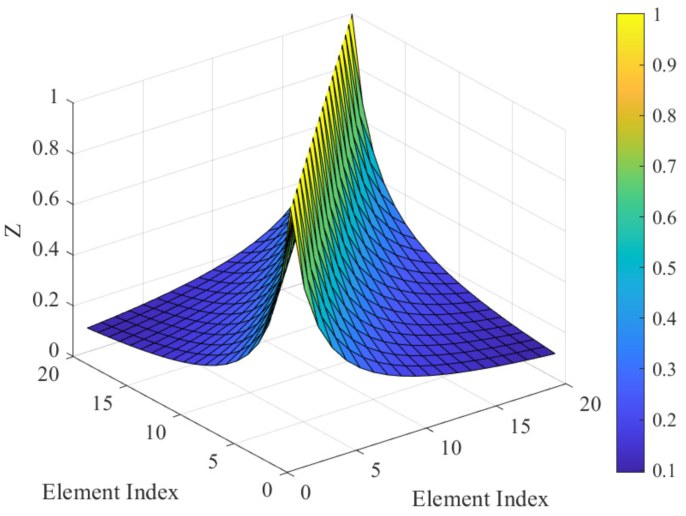
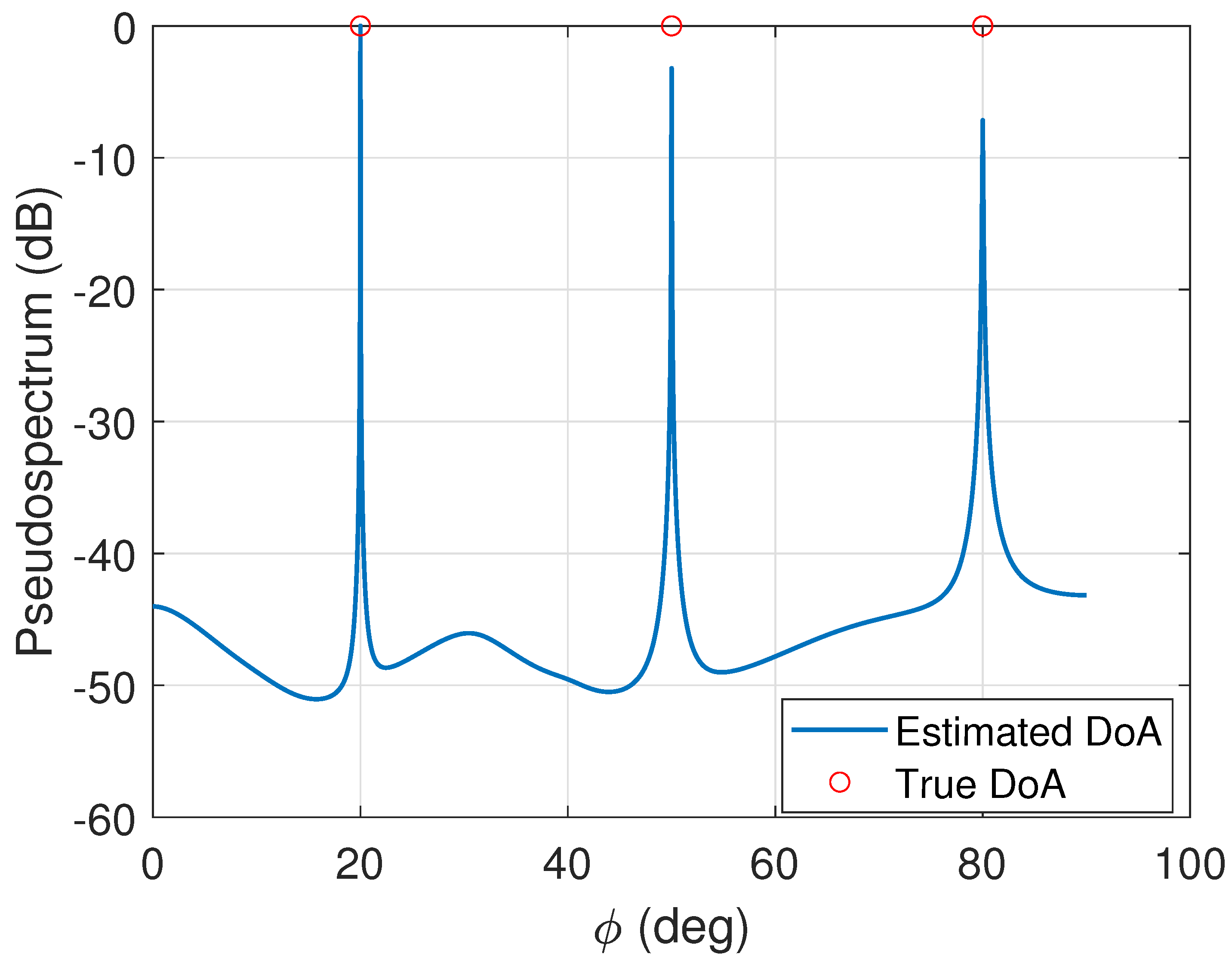
5.2. Performance Illustration of Feature Extraction

Figure 4 illustrates the relationship between the root mean square error (RMSE) of MC and the signal-to-noise Ratio (SNR), which is used to assess the extraction accuracy of the MC features under the settings of ( M = 10 , N = 8 , K = 128 , and L = 3 ). It is clearly demonstrated from Figure 4 that the RMSE for both the real and imaginary parts of the MC features gradually decreases as the SNR improves, indicating an improvement in feature extraction precision. Note that a more accurate feature extraction allows for a clearer distinction between legitimate users and attackers, which is crucial for improving the reliability and accuracy of identity verification.
It should be noted that mutual coupling (MC) characteristics are influenced by antenna geometry, inter-element spacing, and the surrounding electromagnetic environment. In practical deployments, factors such as nearby materials, user mobility, and platform-induced scattering may introduce temporal variations in MC, which could impact the stability of authentication performance. Future work will focus on evaluating the robustness of the proposed scheme under such dynamic conditions through over-the-air (OTA) experiments utilizing programmable antenna arrays and software-defined radio (SDR) platforms.
Figure 5 and Figure 6 present the pseudospectra for DoA and DoD estimation, respectively. In both figures, we observe that each of the three largest peaks corresponds accurately to the true values of the angles θ and ϕ , respectively. Importantly, no false peaks are observed, indicating that the estimation method is highly reliable. Accurate identification of the DoA and DoD is crucial for the successful decoupling of the MC features. By precisely estimating the arrival and departure angles, the MC features can be more effectively isolated and analyzed, leading to better performance in feature extraction and, consequently, in the overall authentication process. This high level of accuracy ensures that the system can distinguish between different signal sources and refine its decision-making process in real-time authentication applications.

5.3. Model Validation

To validate the accuracy of the proposed theoretical framework, in Figure 7, we compare the simulation results with the theoretical models under different SNR levels of { 0 , 5 , 10 } dB. It is observed that the simulation results closely match the theoretical curves derived from Equations (45) and (46). This alignment between theory and simulation validates the correctness of the proposed theoretical performance metric models. The close match between the theoretical and simulation results indicates the reliability and accuracy of the derived analytical expressions for the kernelized detector scheme. This further implies that the established theoretical models can be effectively applied for precise performance characterization. Additionally, we observe that with the increase in SNR, higher P d can be achieved under the same P f constraint. For instance, given a fixed P f = 0.1 , P d under three SNR conditions are 0.73, 0.84, and 0.91, respectively.

5.4. Impacts of System Parameters on Authentication Performance

We first illustrate in Figure 8 the impact of frame length K on the proposed scheme. As shown in Figure 8, it is observed that with the increase in K, the authentication performance improves, demonstrating an upward trend in P d . However, we also note that the performance gain reaches a saturation point as K increases further. For instance, when P f = 0.1 , P d under K = { 32 , 64 , 128 } are 0.59, 0.66, and 0.67, respectively. This indicates that increasing K improves the detection rate, but the performance gain diminishes as K approaches a certain value. In addition, further increases in frame length yield minimal improvement in detection accuracy. Considering the balance between authentication performance and system efficiency, an appropriate K = 64 is selected to avoid unnecessary communication overhead.
Then, in Figure 9, we assess the impact of fingerprint similarity between legitimate users and attackers on the detection performance of the proposed authentication scheme under the settings of SNR = {0, 5, 10} dB. The parameter σ Ψ varies from 1 to 1.8, with σ Ψ = 1.8 representing the worst-case scenario. As shown in Figure 9, P d exhibits a decreasing tendency as σ Ψ increases. Despite this, even in the worst-case scenario, the proposed scheme maintains a detection probability of 0.68, 0.84, and 0.90 at σ Ψ = 1.8 for SNR of 0 dB, 5 dB, and 10 dB, respectively. These results demonstrate the robustness of the proposed scheme, which can be attributed to the amplitude of the MC feature to maintain reliable identity authentication. This additional security layer ensures that the authentication performance remains acceptable under challenging conditions.

5.5. Performance Comparison

In this subsection, we present a performance comparison among the proposed authentication scheme using only the phase of MC, and the proposed authentication scheme using both the amplitude and phase of MC feature under two different SNR conditions: 0 dB and 5 dB. As shown in Figure 10, the authentication scheme that utilizes both amplitude and phase features of MC performs significantly better than the scheme using only the phase, especially under lower SNR conditions. For example, given a P f = 0.2 , P d of the two feature-based scheme is 0.75 while P d of the phase-based scheme is 0.66 under SNR = 0 dB. For SNR = 5 dB, the P d values corresponding to the two cases are 0.86 and 0.82, respectively. The results suggest that exploiting both amplitude and phase features significantly enhances the detection accuracy, as it provides a more comprehensive analysis of the received signals, thereby improving the overall authentication decision-making process. This comparison underscores the importance of incorporating multiple features from the MC feature, leading to more reliable and accurate authentication in challenging scenarios with varying SNR conditions.

6. Conclusions

In this paper, we proposed a robust authentication scheme that leverages both the amplitude and phase of the MC feature to improve the accuracy and reliability of identity verification. In particular, we exploited the zero-mean generalized Gaussian and Laplacian distributions to model the statistical feature regarding the amplitude and phase of MC feature. Based on the modeled statistical knowledge, we then constructed a kernel-based test statistic to design an amplitude-phase based identity authentication scheme. Moreover, we also performed a theoretical analysis of the proposed scheme by deriving the analytical expressions of detection and false alarm probabilities. The results demonstrate that: (1) our theoretical models effectively depict authentication performance in terms of false alarm and detection probabilities; (2) incorporating both amplitude and phase features significantly enhances detection accuracy; (3) the proposed scheme remains robust across various SNR levels, ensuring reliable authentication even in a noise-interference environment. We hope the proposed scheme can hold promise as an effective solution to mitigate identity-based impersonation attacks in mmWave communication systems.
While the proposed framework demonstrates promising authentication capabilities using MC features, several real-world considerations must be addressed before deployment. First, the current evaluation is based on simulations and theoretical modeling; future work will involve experimental validation using SDR-based prototypes to assess robustness under realistic hardware and environmental conditions. Second, the susceptibility of MC profiles to hardware degradation such as antenna failures, RF front-end malfunctions, or calibration drift, can result in inconsistent fingerprints and degraded authentication performance. Third, physical changes in the environment (e.g., moving objects, weather fluctuations, or platform vibrations) may alter the electromagnetic coupling between antenna elements. These factors highlight the need for adaptive re-learning schemes, robustness-aware thresholds, and possibly the fusion of MC with other stable hardware or channel-based features to enhance resilience. Exploring these directions will be the focus of our future research.

Author Contributions

Conceptualization, M.N. and A.N.; methodology, M.N. and R.W.; validation, M.N. and R.W.; investigation, M.N. and A.N.; writing—original draft preparation, P.Z.; writing, review and editing, P.Z. All authors have read and agreed to the published version of the manuscript.

Funding

This work was supported in part by a Natural Science Foundation of China (NSFC) grant (62272241), a Japan Society for the Promotion of Science (JSPS) grant (18H03235), and a Nanjing University of Posts and Telecommunications Scientific Research Foundation grant (NY221122).

Data Availability Statement

The original contributions presented in this study are included in the article. Further inquiries can be directed to the corresponding author.

Conflicts of Interest

The authors declare no conflicts of interest.

Appendix A

D 1 = 1 erfc 2 σ Ψ , ϵ σ Ψ 2 erf 2 σ Ψ , ϵ σ Ψ + erfc 2 2 σ Ψ , ϵ σ Ψ erfc 2 σ Ψ , ϵ σ Ψ 2 erf 2 σ Ψ , ϵ σ Ψ erf 2 2 σ Ψ , ϵ σ Ψ
D 2 = erfc 2 σ Ψ , ϵ 2 + η 2 σ Ψ σ Ψ , ϵ 2 σ Ψ σ Ψ , ϵ 2 + η 2 erfc 2 σ Ψ , ϵ 2 + η 2 σ Ψ 2 erf 2 ( σ Ψ , ϵ 2 + η 2 ) σ Ψ erf 2 ( σ Ψ , ϵ 2 + η 2 ) σ Ψ 2 σ Ψ , ϵ 2 σ Ψ σ Ψ , ϵ 2 + η 2 + erfc 2 σ Ψ , ϵ 2 + η 2 σ Ψ + σ Ψ , ϵ 2 σ Ψ σ Ψ , ϵ 2 + η 2 erfc 2 σ Ψ , ϵ 2 + η 2 σ Ψ 2 erf 2 ( σ Ψ , ϵ 2 + η 2 ) σ Ψ erf 2 ( σ Ψ , ϵ 2 + η 2 ) σ Ψ + 2 σ Ψ , ϵ 2 σ Ψ σ Ψ , ϵ 2 + η 2
D 3 = erfc 2 σ Ψ , ϵ σ Ψ + σ Ψ , ϵ 2 + η 2 σ Ψ σ Ψ , ϵ erfc 2 σ Ψ , ϵ σ Ψ 2 erf 2 2 σ Ψ , ϵ σ Ψ erf 2 σ Ψ , ϵ σ Ψ + σ Ψ , ϵ 2 + η 2 σ Ψ , ϵ σ Ψ erfc 2 σ Ψ , ϵ σ Ψ σ Ψ , ϵ 2 + η 2 σ Ψ , ϵ σ Ψ 1 + 4 erf σ Ψ , ϵ 2 + η 2 σ Ψ , ϵ σ Ψ 2 erf 2 σ Ψ , ϵ σ Ψ + σ Ψ , ϵ 2 + η 2 σ Ψ , ϵ σ Ψ
D 4 = 1 erfc 2 σ Ψ , ϵ 2 + η 2 σ Ψ σ Ψ , ϵ 2 σ Ψ σ Ψ , ϵ 2 + η 2 2 erf 2 2 ( σ Ψ , ϵ 2 + η 2 ) σ Ψ 2 σ Ψ , ϵ 2 σ Ψ σ Ψ , ϵ 2 + η 2 + erfc 2 2 ( σ Ψ , ϵ 2 + η 2 ) σ Ψ erfc 2 σ Ψ , ϵ 2 + η 2 σ Ψ + σ Ψ , ϵ 2 σ Ψ σ Ψ , ϵ 2 + η 2 2 erf 2 ( σ Ψ , ϵ 2 + η 2 ) σ Ψ + 2 σ Ψ , ϵ 2 σ Ψ σ Ψ , ϵ 2 + η 2 erf 2 2 ( σ Ψ , ϵ 2 + η 2 ) σ Ψ
D 5 = erfc 2 σ Ψ , ϵ σ Ψ + σ Ψ , ϵ 2 + η 2 σ Ψ σ Ψ , ϵ 2 erfc 2 σ Ψ , ϵ σ Ψ + σ Ψ , ϵ 2 + η 2 σ Ψ σ Ψ , ϵ erfc 2 σ Ψ , ϵ σ Ψ σ Ψ , ϵ 2 + η 2 σ Ψ σ Ψ , ϵ + 4 erf σ Ψ , ϵ σ Ψ σ Ψ , ϵ 2 + η 2 σ Ψ σ Ψ , ϵ 2 1 + erf σ Ψ , ϵ σ Ψ 2 σ Ψ , ϵ 2 + η 2 σ Ψ σ Ψ , ϵ
D 6 = erfc 2 2 σ Ψ , ϵ 2 + η 2 σ Ψ 2 erfc 2 2 ( σ Ψ , ϵ 2 + η 2 ) σ Ψ 1 2

References

  1. Alouzi, M.; Yanikomeroglu, H.; Kurt, G.K. Adaptive Phase Shifters for Hybrid Beamforming in mmWave Systems. IEEE Trans. Wirel. Commun. 2025, 24, 1104–1116. [Google Scholar] [CrossRef]
  2. Wan, Q.; Fang, J.; Chen, Z.; Li, H. Hybrid Precoding and Combining for Millimeter Wave/Sub-THz MIMO-OFDM Systems With Beam Squint Effects. IEEE Trans. Veh. Technol. 2021, 70, 8314–8319. [Google Scholar] [CrossRef]
  3. Chen, K.; Qi, C.; Wang, C.; Li, G.Y. Beam Training and Tracking for Extremely Large-Scale MIMO Communications. IEEE Trans. Wirel. Commun. 2024, 23, 5048–5062. [Google Scholar] [CrossRef]
  4. Li, Z.; Luo, X.; Chen, M.; Xu, C.; Mao, S.; Liu, Y. Contextual Combinatorial Beam Management via Online Probing for Multiple Access mmWave Wireless Networks. IEEE J. Sel. Areas Commun. 2025, 43, 959–972. [Google Scholar] [CrossRef]
  5. Xu, W.; Gao, F.; Tao, X.; Zhang, J.; Alkhateeb, A. Computer Vision Aided mmWave Beam Alignment in V2X Communications. IEEE Trans. Wirel. Commun. 2023, 22, 2699–2714. [Google Scholar] [CrossRef]
  6. Sun, Z.; Balakrishnan, S.; Su, L.; Bhuyan, A.; Wang, P.; Qiao, C. Who Is in Control? Practical Physical Layer Attack and Defense for mmWave-Based Sensing in Autonomous Vehicles. IEEE Trans. Inf. Forensics Secur. 2021, 16, 3199–3214. [Google Scholar] [CrossRef]
  7. Zheng, T.; Wen, Y.; Liu, H.; Ju, Y.; Wang, H.; Wong, K.; Yuan, J. Physical-Layer Security of Uplink mmWave Transmissions in Cellular V2X Networks. IEEE Trans. Wirel. Commun. 2022, 21, 9818–9833. [Google Scholar] [CrossRef]
  8. Wang, H.; Ju, Y.; Zhang, N.; Pei, Q.; Liu, L.; Dong, M.; Leung, V.C.M. Resisting Malicious Eavesdropping: Physical Layer Security of mmWave MIMO Communications in Presence of Random Blockage. IEEE Internet Things J. 2022, 9, 16372–16385. [Google Scholar] [CrossRef]
  9. Yang, Z.; Kang, M.; Teoh, A.B.J.; Gao, C.; Chen, W.; Zhang, B.; Zhang, Y. A Dual-Level Cancelable Framework for Palmprint Verification and Hack-Proof Data Storage. IEEE Trans. Inf. Forensics Secur. 2024, 19, 8587–8599. [Google Scholar] [CrossRef]
  10. Hu, Y.; Bian, W.; Xie, D.; Xu, D.; Xu, Z. Secure and Efficient Industrial Wireless Sensor Networks Protocol Based on Cancelable Biometrics. IEEE Trans. Ind. Inform. 2024, 20, 13580–13590. [Google Scholar] [CrossRef]
  11. Xie, N.; Zhang, J.; Zhang, Q.; Tan, H.; Liu, A.X.; Niyato, D. Hybrid Physical-Layer Authentication. IEEE Trans. Mob. Comput. 2024, 23, 1295–1311. [Google Scholar] [CrossRef]
  12. Li, Y.; Zhang, J.; Chen, J.; Chen, Y.; Xie, N.; Li, H. Privacy-Preserving Physical-Layer Authentication Under Cooperative Attacks. IEEE/ACM Trans. Netw. 2024, 32, 1171–1186. [Google Scholar] [CrossRef]
  13. Wang, C.; Sha, M.; Xiong, W.; Xie, N.; Mao, R.; Zhang, P.; Huang, L. Blind Tag-Based Physical-Layer Authentication. IEEE/ACM Trans. Netw. 2024, 32, 4735–4748. [Google Scholar] [CrossRef]
  14. Tang, J.; Xu, A.; Jiang, Y.; Zhang, Y.; Wen, H.; Zhang, T. MmWave MIMO Physical layer Authentication by Using Channel Sparsity. In Proceedings of the 2020 IEEE International Conference on Artificial Intelligence and Information Systems (ICAIIS), Dalian, China, 20–22 March 2020; pp. 221–224. [Google Scholar] [CrossRef]
  15. Xiao, L.; Greenstein, L.J.; Mandayam, N.B.; Trappe, W. Channel-based detection of sybil attacks in wireless networks. IEEE Trans. Inf. Forensics Secur. 2009, 4, 492–503. [Google Scholar] [CrossRef]
  16. Zhang, P.; Zhu, J.; Chen, Y.; Jiang, X. End-to-End Physical Layer Authentication for Dual-Hop Wireless Networks. IEEE Access 2019, 7, 38322–38336. [Google Scholar] [CrossRef]
  17. Ferrante, A.; Laurenti, N.; Masiero, C.; Pavon, M.; Tomasin, S. On the Error Region for Channel Estimation-Based Physical Layer Authentication Over Rayleigh Fading. IEEE Trans. Inf. Forensics Secur. 2015, 10, 941–952. [Google Scholar] [CrossRef]
  18. Wang, N.; Jiao, L.; Alipour-Fanid, A.; Dabaghchian, M.; Zeng, K. Pilot Contamination Attack Detection for NOMA in 5G mm-Wave Massive MIMO Networks. IEEE Trans. Inf. Forensics Secur. 2020, 15, 1363–1378. [Google Scholar] [CrossRef]
  19. Wang, N.; Jiao, L.; Wang, P.; Li, W.; Zeng, K. Exploiting beam features for spoofing attack detection in mmWave 60-GHz IEEE 802.11 ad networks. IEEE Trans. Wirel. Commun. 2021, 20, 3321–3335. [Google Scholar] [CrossRef]
  20. Zhang, J.; Woods, R.; Sandell, M.; Valkama, M.; Marshall, A.; Cavallaro, J. Radio Frequency Fingerprint Identification for Narrowband Systems, Modelling and Classification. IEEE Trans. Inf. Forensics Secur. 2021, 16, 3974–3987. [Google Scholar] [CrossRef]
  21. Zhao, C.; Huang, M.; Huang, L.; Du, X.; Guizani, M. A robust authentication scheme based on physical-layer phase noise fingerprint for emerging wireless networks. Comput. Netw. 2017, 128, 164–171. [Google Scholar] [CrossRef]
  22. Polak, A.C.; Goeckel, D.L. Wireless Device Identification Based on RF Oscillator Imperfections. IEEE Trans. Inf. Forensics Secur. 2015, 10, 2492–2501. [Google Scholar] [CrossRef]
  23. Maeng, S.J.; Yapici, Y.; Güvenç, I.; Dai, H.; Bhuyan, A. Power Allocation for Fingerprint-Based PHY-Layer Authentication with mmWave UAV Networks. In Proceedings of the ICC 2021—IEEE International Conference on Communications, Montreal, QC, Canada, 14–23 June 2021; pp. 1–6. [Google Scholar]
  24. Shi, Y.; Jensen, M.A. Improved Radiometric Identification of Wireless Devices Using MIMO Transmission. IEEE Trans. Inf. Forensics Secur. 2011, 6, 1346–1354. [Google Scholar] [CrossRef]
  25. Lou, S.; Qian, S.; Wang, W. Influence of Random Errors in Element Positions on Performance of Antenna Arrays Considering Mutual Coupling Effect. IEEE Antennas Wirel. Propag. Lett. 2023, 22, 2215–2219. [Google Scholar] [CrossRef]
  26. Balanis, C.A. Antenna Theory: Analysis and Design, 4th ed.; John Wiley & Sons: Hoboken, NJ, USA, 2016. [Google Scholar]
  27. Azam, M.A.; Dutta, A.K.; Mukherjee, A. Performance Analysis of Dipole Antenna Based Planar Arrays With Mutual Coupling and Antenna Position Error in mmWave Hybrid System. IEEE Trans. Veh. Technol. 2021, 70, 10209–10221. [Google Scholar] [CrossRef]
  28. Lee, S.; Song, H.J. Accurate Statistical Model of Radiation Patterns in Analog Beamforming Including Random Error, Quantization Error, and Mutual Coupling. IEEE Trans. Antennas Propagat. 2021, 69, 3886–3898. [Google Scholar] [CrossRef]
  29. Chen, P.; Cao, Z.; Chen, Z.; Wang, X. Off-Grid DOA Estimation Using Sparse Bayesian Learning in MIMO Radar With Unknown Mutual Coupling. IEEE Trans. Signal Process. 2019, 67, 208–220. [Google Scholar] [CrossRef]
  30. Hemadeh, I.A.; Satyanarayana, K.; El-Hajjar, M.; Hanzo, L. Millimeter-Wave Communications: Physical Channel Models, Design Considerations, Antenna Constructions, and Link-Budget. IEEE Commun. Surv. Tutor. 2018, 20, 870–913. [Google Scholar] [CrossRef]
  31. Fan, D.; Gao, F.; Liu, Y.; Deng, Y.; Wang, G.; Zhong, Z.; Nallanathan, A. Angle Domain Channel Estimation in Hybrid Millimeter Wave Massive MIMO Systems. IEEE Trans. Wirel. Commun. 2018, 17, 8165–8179. [Google Scholar] [CrossRef]
  32. Joint DOD and DOA estimation of bistatic MIMO radar in the presence of unknown mutual coupling. Signal Process. 2012, 92, 3039–3048. [CrossRef]
  33. Baracca, P.; Laurenti, N.; Tomasin, S. Physical layer authentication over MIMO fading wiretap channels. IEEE Trans. Wirel. Commun. 2012, 11, 2564–2573. [Google Scholar] [CrossRef]
  34. Margoosian, A.; Abouei, J.; Plataniotis, K.N. An Accurate Kernelized Energy Detection in Gaussian and non-Gaussian/Impulsive Noises. IEEE Trans. Signal Process. 2015, 63, 5621–5636. [Google Scholar] [CrossRef]
  35. Serfling, R.J. Approximation Theorems of Mathematical Statistics; John Wiley & Sons: New York, NY, USA, 2009. [Google Scholar]
  36. Trees, H.L.V.; Bell, K.L.; Tian, Z. Detection, Estimation, and Modulation Theory, Part I: Detection, Estimation, and Filtering Theory, 2nd ed.; Wiley: Hoboken, NJ, USA, 2014. [Google Scholar]
  37. Gu, Z.; Chen, H.; Xu, P.; Li, Y.; Vucetic, B. Physical Layer Authentication for non-Coherent Massive SIMO-Enabled Industrial IoT Communications. IEEE Trans. Inf. Forensics Secur. 2020, 15, 3722–3733. [Google Scholar] [CrossRef]
  38. Xie, N.; Chen, C.; Ming, Z. Security Model of Authentication at the Physical Layer and Performance Analysis over Fading Channels. IEEE Trans. Depend. Sec. Comput. 2021, 18, 253–268. [Google Scholar] [CrossRef]
  39. Xie, F.; Pang, Z.; Wen, H.; Lei, W.; Xu, X. Weighted Voting in Physical Layer Authentication for Industrial Wireless Edge Networks. IEEE Trans. Ind. Inform. 2022, 18, 2796–2806. [Google Scholar] [CrossRef]
  40. Ding, G.; Wu, Q.; Yao, Y.D.; Wang, J.; Chen, Y. Kernel-Based Learning for Statistical Signal Processing in Cognitive Radio Networks: Theoretical Foundations, Example Applications, and Future Directions. IEEE Signal Process. Mag. 2013, 30, 126–136. [Google Scholar] [CrossRef]
  41. Gradshteĭn, I.S.; Ryzhik, I.M.; Jeffrey, A. Table of Integrals, Series, and Products, 7th ed.; Academic Press: Amsterdam, The Netherlands; Boston, MA, USA, 2007. [Google Scholar]
  42. Nadarajah, S.; Kotz, S. On the linear combination, product and ratio of normal and Laplace random variables. J. Frankl. Inst. 2011, 348, 810–822. [Google Scholar] [CrossRef]
Figure 1. System model.
Electronics 14 02055 g001
Figure 2. Transmitting mode coupling paths between antennas m 1 and m 2 .
Electronics 14 02055 g002
Figure 3. Magnitude of the normalized impedance matrix elements for a ULA of 20 dipoles spaced λ / 2 apart.
Electronics 14 02055 g003
Figure 4. RMSE performance versus SNR.
Electronics 14 02055 g004
Figure 5. The pseudospectrum for DoA estimation.
Electronics 14 02055 g005
Figure 6. The pseudospectrum for DoD estimation.
Electronics 14 02055 g006
Figure 7. Model validation for the proposed theoretical performance metrics.
Electronics 14 02055 g007
Figure 8. ROC performance versus K.
Electronics 14 02055 g008
Figure 9. Detection performance versus σ Ψ .
Electronics 14 02055 g009
Figure 10. Performance comparison.
Electronics 14 02055 g010
Table 1. Bounded kernel functions.
Kernel NameExpression
Gaussian Ω ( x i , x j ) = exp x i x j 2 2 η 2
Laplacian Ω ( x i , x j ) = exp x i x j 2 η 2
Disclaimer/Publisher’s Note: The statements, opinions and data contained in all publications are solely those of the individual author(s) and contributor(s) and not of MDPI and/or the editor(s). MDPI and/or the editor(s) disclaim responsibility for any injury to people or property resulting from any ideas, methods, instructions or products referred to in the content.

