Article

Smart Water ATM with Arduino Integration, RFID Authentication, and Dynamic Dispensing for Enhanced Hydration Practices

College of Engineering, Science and Environment, University of Newcastle, Callaghan, NSW 2308, Australia
*
Author to whom correspondence should be addressed.
Electronics 2024, 13(9), 1657; https://doi.org/10.3390/electronics13091657
Submission received: 21 February 2024 / Revised: 19 April 2024 / Accepted: 25 April 2024 / Published: 25 April 2024

Abstract

:
This proposal outlines the development of a comprehensive solution to address hydration challenges through the creation of a Smart Water ATM with Arduino integration, RFID authentication, and dynamic dispensing capabilities. Traditional water dispensers often fall short in monitoring water intake and promoting optimal hydration practices. In response, our project aims to revolutionize hydration practices by integrating Arduino Mega and Uno boards into a Smart Water ATM with a Bottle Dispenser. This innovative system is designed to dispense specific water quantities based on user preferences, encourage the use of personal water bottles, display water temperature, and operate independently without the need for a water line connection. Prior to prototype fabrication, an extensive literature review and survey were conducted to understand existing water dispenser shortcomings and gather public perspectives in Singapore. The Smart Water ATM addresses identified issues by incorporating sensors to monitor water levels, dispense specific quantities, and measure water temperatures. The prototype fabrication involves designing a stainless-steel housing, 3D printing the Smart Water dispenser unit, and installing tanks, tubing, and electronic components. To enhance user interaction, the Smart Water ATM requires RFID authentication through Identity Cards, tracking daily water consumption. An LCD screen displays the dispensed water volume over the ATM’s lifespan, motivating users to be mindful of their water consumption and minimize wastage. Adjustments will be made for deployment in public spaces, such as train stations, where access to permanent water dispensers is limited. This proposal presents an innovative solution to promote enhanced hydration practices, encouraging users to adopt mindful water consumption habits.

1. Introduction

In 1938, American inventor Luther Haws introduced the first electric water cooler capable of dispensing both hot and cold water. In Singapore, there are currently two types of water coolers: POU (Point of Use) and bottled water dispensers. POU water dispensers require a connection to a water supply line, while bottled water dispensers require water delivery in large bottles from vendors. Depending on the model, these large bottles can either be top-mounted or bottom-loaded. When it comes to the optimal maintenance of water coolers, the preferred method is to connect it directly to waste drains. However, Bottled Water Dispensers have an integral wastewater collector that must be emptied, cleaned, and disinfected periodically according to the manufacturer’s instructions.
Each school in Singapore has Point of Use water coolers located beside every toilet to encourage students to hydrate themselves [1]. These water coolers are all linked to the water supply lines, which provide tap water. The primary function of these water coolers is to dispense water to fill water bottles. There were two pipes—one for drinking directly and one to fill up water bottles—providing hot and cold water access. A more recent innovation involves water dispensers equipped with infrared sensors, enabling them to dispense water when they sense a person standing in front of them. These dispensers provide water for direct consumption and for filling water bottles. As seen in Figure 1, this innovative technology can be found near every restroom at Changi Airport. West Coast Park features water coolers in every restroom. Additionally, along the walkway, there is a water dispenser conveniently placed every 200 m for direct drinking.
The common assumption in Singapore is that the pipe water is clean. Therefore, POU water coolers are attached to the existing water line. At places where no water lines are found, vending machines dispense mineral water bottles and other flavored drinks at a cost.
The motivation behind this current project is as follows:
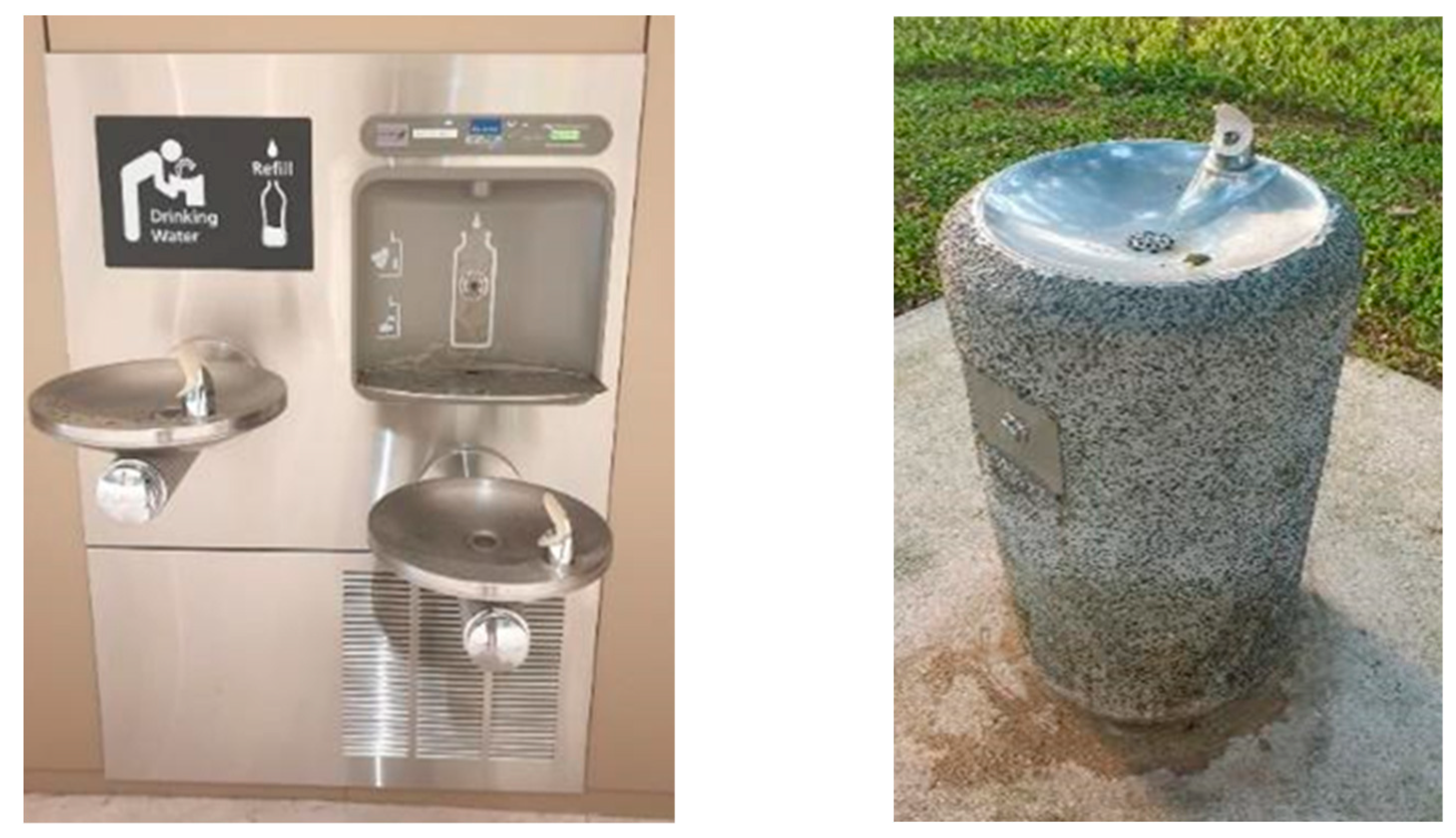
  • Most of the water coolers in Singapore are the Point of Use (POU) type, which must be attached to existing water lines. Hence, there are concerns about hygiene and proximity to the bathroom.
  • At eating establishments such as food centers, water coolers may face hygiene issues caused by individuals spitting saliva or phlegm. This contamination can compromise the cleanliness of the water dispenser. This might discourage potential users who are put off by its unappealing appearance.
  • Existing water coolers in Singapore function in a conventional manner where users need to press a button to regulate the water flow from the nozzle. This increases the likelihood of spillage and scalding.
  • Traditional water coolers only dispense water without tracking the user’s water intake. Therefore, it does not monitor and remind individual users to drink up.
Therefore, the project aims to create a semi-automated Smart Water ATM that encourages users to drink water and carry a water bottle with them. This Smart Water ATM will be able to operate independently, without requiring connection to water lines.
There are 4 different sections in this project: Mechanical design, Electrical design, Software design, and Assembly. These five sections must be accomplished in individual ways to achieve a successful project completion. After these sections, a mobile application will be developed to work with the Smart water dispenser to track and monitor individuals’ water intake.

2. Literature Review

Smart water dispensers have already been researched and many journal articles have been written on them before. However, most of the Smart Water ATM journal articles are focused on less developed countries where water is scarce. In this literature review, we will be covering the types of Smart Water ATMs people have researched for various purposes, as well as exploring how the water level in the storage tanks is monitored, case studies of Smart Water ATMs that have been implemented at certain places, and how these can help with the design of the proposed prototype for their usage in Singapore.

2.1. Types of Smart Water ATMs

The Smart Water dispenser focuses on two main functions: to measure the temperature of the environment to notify the user about how much water he/she must consume and to alert if the number of bottles is low for dispensing for its vendor to perform a refill [2]. Previously, Smart Water dispensers functioned as that of a bottled drink vending machine; the overall weight of the bottles was measured. In contrast, a Smart Water dispensing dystem was developed such that it dispenses water without packaging [3]. Instead of monitoring the overall weight to see if it is running low on water, the water level of the storage tank itself is being monitored. A float sensor in the storage tank detects the low level and triggers the pump to refill the tank from the main water line. This process eliminates the need for manual refills by vendors, making it an automated refill system, as compared to [1]. Regarding the dispensing method, a contactless water dispensing system was implemented [3]. This system functions similarly to the water cooler system at Changi Airport terminals, where users trigger the dispenser by standing near it. An infrared sensor activates the dispensing process, allowing users to access water without physical contact. Unlike the above-mentioned Smart Water dispensers, a Smart Water dispenser that operates as an RFID card and coin-operated water ATM was developed in [4]. This is very similar to vending machines in developing countries that support both coin and bank card payments. The focus was to find a solution to making a Smart Water ATM that can be used by any caste without discrimination. The targeted locations of these dispensers were to be on highways, railway stations, and public places, especially available after working hours [4]. Similarly, a secure integrated water ATM that functions as a vending machine for water was developed in [5]. However, they also aimed to replace existing water ATMs with Smart Water ATMs to prevent water theft and gather data for the government regarding people’s water consumption. To accomplish this goal, the design integrates several key components, including a biometric sensor, a flow meter, and a solenoid valve. The biometric sensor securely stores users’ fingerprints in a database, ensuring that only authorized individuals can access the water supply. Meanwhile, the solenoid valve regulates the dispensing of water, and the flow meter accurately measures the volume of water being dispensed. All relevant data, including the user’s fingerprint and the amount of water consumed, is meticulously recorded in the database. Diverging from conventional Smart Water ATMs, this system operates on a billing basis, wherein users are invoiced by the providers for the water they have utilized. Subsequently, users receive a detailed statement delineating the quantity of water consumed and the corresponding payment, alleviating the need for immediate transactions.

2.2. Various Ways of Monitoring Water Level

A Smart Water dispensing system that employs sensors, microcontrollers, and mobile technology for real-time monitoring and controlled dispensation was proposed in [3]. Their approach not only minimizes water waste but also enhances security through mobile payment systems. In a similar system, a cost-effective solution utilizing an Arduino Uno microcontroller, an LM016L LCD, and an ultrasonic sensor for monitoring water levels is seen in [6]. This system’s scalability and ease of implementation make it an attractive option for various settings. In line with the advent of the Internet of Things (IoT), an IoT- and Android-based platform for water level monitoring, highlighting its potential for secure, scalable, and efficient water management, was introduced [7]. These innovative approaches collectively underscore the importance of leveraging technology to ensure accurate, accessible, and sustainable water level monitoring [3,6,7]. By addressing the limitations of traditional methods and embracing advancements in sensors, microcontrollers, and mobile interfaces, researchers are contributing to a more holistic approach to water resource management. Further research and development in this field hold the promise of improved efficiency, reduced wastage, and enhanced conservation efforts.

2.3. Various Ways of Measuring Water Flow

In the paper, the authors propose a comprehensive Smart Water dispenser monitoring system that utilizes a microcontroller and various sensors to collect and transmit data [8]. The system employs a microcontroller connected to sensors that measure water level, temperature, and flow rate. These parameters are then transmitted to a cloud server via Wi-Fi where authorized users can access the data through a web interface. This approach enables real-time monitoring of dispenser conditions, helping to identify issues such as low water levels, malfunctioning units, and maintenance requirements. The system’s ability to prevent water wastage and ensure dispenser efficiency aligns with the goal of efficient water management. Furthermore, ref. [9] discusses an innovative approach to measuring water flow rate and volume using an Arduino microcontroller and a Hall effect water flow sensor. The Hall effect sensor generates electrical pulses as water molecules pass through it, allowing the microcontroller to count these pulses and then calculate flow rates and volumes. This method proves accurate and reliable, with applications ranging from irrigation systems to industrial processes. The simplicity of the circuit design and the affordability of the components make this approach adaptable to various settings. Collectively, these two papers underscore the diversity of methods available for measuring water flow. The Smart Water dispenser monitoring system exemplifies the integration of IoT technologies to enhance monitoring and management, while the Arduino-based flow sensor approach showcases a cost-effective and practical means of obtaining accurate measurements. By leveraging technology, both papers contribute to improved water resource utilization and more informed decision-making processes.

2.4. Case Studies of Implemented Water ATMs

In addition to designing the hardware for water dispensers, extensive research was conducted to grasp the socio-economic challenges associated with installing and using such dispensers in less developed countries. In Sarkar’s 2019 paper, “Smart Technology to Serve Urban Poor: A Case Study of Water ATMs in a Nairobi Slum”, there was an investigation into Nairobi’s Mathare slum to enhance clean water access [10]. It revealed that while water ATMs improved water quality for some, affordability and accessibility challenges remained [10]. The research underscored the importance of ensuring affordability and equitable distribution alongside water ATM implementation. In Kumar’s 2018 paper, “Water ATMs of Indian Railways: Causing a Silent Revolution”, he investigated how to enhance water access for passengers and staff. The case study highlighted the positive impact of water ATMs in improving quality of life and reducing waterborne diseases. The study also demonstrated the financial sustainability benefits of revenue generation from water ATM operations [11]. In Schmidt’s 2020 paper [12], “Pop-up Infrastructure: Water ATMs and New Delivery Networks in India”, he critically analyzed the emergence of water ATMs as a novel water infrastructure in India. The study emphasized advantages in water quality and convenience (Schmidt, 2020), while also noting potential disruptions to existing delivery networks and implications for inequality. Schmidt also highlighted the importance of cautious implementation and socio-economic considerations.
In the 2022 paper “Water ATMs and Access to Water: Digitalization of Off-Grid Water Infrastructure in Peri-Urban Ghana” by Amankwaa, Heeks, and Browne [13], they explored water ATM implementation in a peri-urban Ghanaian community. The study highlighted water ATMs’ incremental nature shaped by socio-material dynamics [13]. The case study emphasized the significance of a situated socio-technical approach, stakeholder engagement, affordability, accessibility, and leveraging existing community infrastructures. The case studies of implemented water ATMs provide valuable insights into the complexities of water access challenges, technological solutions, and socio-economic considerations. Hence, there have been huge advancements in features ever since the first implemented IoT Smart Water bottle [14]. While water ATMs offer advantages in water quality and access, they also raise questions about affordability, accessibility, and potential disruptions to existing networks. By adopting a context-specific approach, policymakers and practitioners can effectively navigate water ATM implementation, ensuring sustainable and equitable water access for communities in need.

2.5. Summary

To summarize, this literature review explores existing research on Smart Water dispensers, particularly focusing on the usage of these dispensers in less developed countries and their potential application in Singapore. The review covers various types of Smart Water ATMs, including those emphasizing temperature monitoring, bottle quantity, contactless dispensing, and RFIC and coin-operated models. Different methods for monitoring water levels and flow, such as sensor-based systems and IoT integration, are discussed. The comprehensive literature review informs the design of the proposed Smart Water ATM prototype for use in Singapore, considering the diverse features and functionalities discussed in the existing research.

3. Proposed Work

Mechanical Design

In this project, there are two different mechanical designs: Structural Frame Housing, for the entire prototype, and the Water Dispensing Unit. The purpose of the structural frame housing for the entire prototype is to house a 17 L reserve water tank, two 6 L water tanks (one dedicated for normal temperature water and another dedicated for warm water), and placement and wiring of all electronic components, as well as placement of the Water Dispensing Unit. The refill tanks are there to control the temperature of the warm water tank and, in the event of water disruption in the main line, the Smart Water ATM will still be functional for a certain time. The water dispensing unit’s purpose is to hold the users’ water bottles and to hold the two silicon tubes coming from either the normal water tank or the warm water tank. A customer survey mentioned above was conducted regarding the type and sizing of bottles used before designing. This design was first done in SolidWorks software (Version 8.4) and then imported into a software called Prusa Slicing before initiating Fused Deposition Modelling (FDM) using Polylactic Acid (PLA) as the material. Based on the required functionality of the prototype, Arduino boards were sourced for microcontrollers, input and output components for users’ interaction, and electronic and electromechanical components for the overall operation of dispensing water from the reserve tank to the users’ water bottles. The details of the important components are listed below. Take note that once the proof of concept has been achieved, better materials will be sourced, especially for those that will be in contact with the drinking water, such as the water pumps, to meet health standards.
The Arduino Uno board stands as a widely acclaimed microcontroller, often heralded as the cornerstone of numerous electronic endeavors, offering a robust and versatile mind for a multitude of projects. Connecting different sensors, actuators, and other electrical components is made possible by its digital and analog input/output ports, which are based on the ATmega328P microcontroller. As the Arduino bootloader is already pre-programmed, users can simply upload code to it over USB without the requirement of an additional programmer. In this prototype, one Arduino Uno board connected to ultrasonic sensors is used to monitor the water level for the three water tanks inside the system, and two LCD screens are used to display: (1) the amount of water used throughout and, (2) the water level of the refillable tank for the vendor to replace if critically low. This is mainly because it is an independent program that does not interfere with the main program and requires little digital input/output as compared to the requirements of the main program. Compared to the Arduino Uno, it has many more digital and analog pins and is based on the ATmega2560 microprocessor. Due to its increased pin count, which includes more serial communication ports and memory, the Arduino Mega is especially well-suited for applications requiring a greater number of inputs and outputs or more intricate calculations. The Arduino Mega board will be used in this prototype as the ‘main brain’ to run the main program, as it is well-suited for complex commands, and the main program involves a significant number of sensors, modules, water pumps, and actuators. A 12 V solenoid valve is an electromechanical device that uses an electromagnetic solenoid to activate the valve mechanism to control the flow of a fluid. The operation of the solenoid valve works such that upon receiving a 12 V electrical signal on the solenoid, a magnetic field is created that moves the plunger/piston inside the valve to open or close. Depending on the desired control mechanism, this action either permits or prohibits the fluid from flowing. This is an essential part of this prototype as this component controls the dispensing of water into the users’ bottles. A popular tool for gauging water flow rates in diverse systems is the Water Flow Sensor FS300A G3/4″. It can precisely monitor the amount of water flowing through it and is usually put in pipelines or water systems. Typically, the sensor has a G3/4″ thread to make it simple to install into typical water pipelines. Based on a turbine or paddle wheel mechanism, the Water Flow Sensor FS300A G3/4″ works by rotating the paddle or turbine in response to water flow. The sensor can offer flow rate data in real time because of this rotation, which produces electrical signals proportionate to the flow rate. The sensor is suitable for a wide range of microcontrollers and electronic systems due to having a digital output. This is another essential component in this prototype as it works together with the 12V Solenoid valve to measure the appropriate amount of water and dispense that amount to the user.
The DC Submersible Pump (DC-1020) is a submersible water pump that can be used for a variety of applications such as water circulation, drainage, and aquarium systems. It is often supplied by a direct current (DC) power source, such as a battery or a solar panel, making it excellent for off-grid and distant applications where AC power is in short supply. The DC Submersible Pump (DC-1020) works by employing a direct current motor to move water through an impeller. When submerged in water, the pump generates a flow by drawing water into its intake and expelling it via its outlet. The tiny and submersible design enables effective water movement and transfer in a variety of situations, such as ponds, fountains, and water-based systems. Silicone Hose FDA (5 bar Φ m12/8) is planned to be used as tubing throughout the prototype to be built. The HC-SR04 Ultrasonic Sensor is a well-known distance-measuring sensor that uses ultrasonic waves to calculate the distance between an object and the sensor. It is made up of a transmitter and a receiver that work together to time how long it takes an ultrasonic pulse to bounce off an object and return to the sensor. The sensor works by producing a short ultrasonic pulse at a frequency exceeding the range of human hearing. The sensor then listens for the echo of the pulse and determines the distance to the item by measuring the time it takes for the echo to return. This type of sensor is used in this prototype to measure the water level in each tank to trigger necessary countermeasures, such as switching on the pump to fill up the tank or to display the water level on the user’s interface.
The DS18B20 is a popular digital temperature sensor capable of accurately measuring temperature with a high degree of precision. It connects several sensors to a single microcontroller pin using a one-wire interface. Depending on the configuration, the sensor can measure temperatures over a large range and offers accurate results with a precision of 9 to 12 bits. The DS18B20 Digital Thermometer’s functions include translating temperature into a digital signal that microcontrollers can understand, making it easier to integrate with different microcontrollers, and doing away with the requirement for analog-to-digital conversion. The 1N4001 is a common rectifier diode found in many electronic devices. It is a silicon diode with a maximum forward current of 1A and a maximum repeated reverse voltage of 50 V. The 1N4001 diode is widely used in rectification and power supply applications to convert alternating current (AC) to direct current (DC) by permitting electricity to flow in just one direction. The 1N4001 diode’s functioning is based on its capacity to pass electrical current in one direction while blocking it in the other. The 1N4001 diode, when linked in a circuit, permits current flow from its anode to its cathode when the voltage across it is in the forward bias direction. It prevents current flow in the reverse bias direction, preventing current flow in the opposite direction. In this prototype, this diode will be used before the connection of the 12 V solenoid valve as the solenoid valve is known to have reverse voltage when switched off, which could lead to frying the overall system if diodes were not used.

4. Method

4.1. Overall Frame Fabrication

The shape of the housing is influenced by a regular-sized vending machine. To handle a minimum weight of 30 kg due to the weight of the water tanks filled with water and the weight of the components, a cupboard-like structure is drawn on SolidWorks software with 3 platforms at various heights. The bottom platform is designed to house the reserve tank and the middle platform to house the two small tanks, while the top platform is to house the electronic components as well as to partially house the water dispenser unit. After finalizing the design and analyzing the results of the survey taken, necessary amendments were made. The structure was then fabricated in an industrial workshop with the necessary tools and equipment as mentioned below. Refer to Appendix A in https://github.com/clkok1/appendix.git for reference. Figure 2 shows the three dimensional cuboid structure.

4.2. Water Dispensing Unit

The shape of the water dispensing unit is influenced by a regular water dispenser capable of holding 2 L of water found in homes. According to the assumption of people carrying a cylindrical shaped water bottle, the dispenser’s platform is designed in a cylindrical way to hold the user’s water bottle. From the customer survey results mentioned above in Section 4.2, the height between the nozzle is designed to fit nearly all of the types of bottles stated by the participants that can hold 1 L of water. Two nozzles were designed such that one was meant for normal-temperature water while the other was meant for warm water. Adjustments were made to the design for an infrared sensor to be mounted. This is to detect the placement of a water bottle so that water from the nozzle can be dispensed to prevent unnecessary spillage. The engineering drawing of the dispenser design can be found in Appendix A in https://github.com/clkok1/appendix.git for more information regarding the dimensions. This was then planned to be printed with the help of a 3D printer using the Fused Deposition Modelling (FDM) method.
However, the design of the water dispensing unit could not be fitted on the 3D printer platform’s printable bed size of dimensions 200 mm by 200 mm because the dispensing unit was planned to be printed while being laid on the horizontal side. The design could not be printed in vertical form either, due to the printer being able to print at a maximum height of only 250 mm, while the water dispensing unit’s height in standing position is 475 mm. Hence, the water dispensing unit must be designed such that it is split into 3 separate parts to ideally fit the required dimensions of 200 mm by 200 mm by 250 mm. It was planned to be assembled back into one piece and secured using tape and epoxy resin. The three cut pieces—Cut Piece 1, Cut Piece 2, and Cut Piece 3—are then 3D printed according to the engineering model designed with the aid of engineering drawings, as found in Appendix A in https://github.com/clkok1/appendix.git. The model is then fed into the 3D printer, shown in Figure 3, as the model’s STL format for the 3D printer to print the three parts. The three different parts are then assembled by slot in type according to the explosive engineering drawing found in Appendix A in https://github.com/clkok1/appendix.git. Epoxy resin is added on the surfaces of the pieces that were connected to stick them together permanently while assembling the pieces. As epoxy resin takes a longer time to settle, tape was pasted along the assembled perimeter to secure the connected cut pieces together to form a 3D-printed water dispenser unit.

4.3. Assembly of Electronic Components

In this section, as shown in Figure 4, the wiring of the electronic components linked with the Arduino boards of the prototype will be covered in terms of their wiring schematics. For this prototype, the Arduino Mega board is used as a master brain, as it has more memory and processing power as compared to the Arduino Uno board. Also, the Arduino Mega board has 54 digital pins, which is far more than an Arduino Uno board, which has 14 digital pins. The Arduino Mega board is connected to the following components: one 128 × 64 LCD Screen, one 4 × 4 Matrix Keypad, two FS300A Water Flow Sensors, four DC 1020 Water Pumps connected through four 12 V relays, two 12 V Solenoid Valves, and some pins in Arduino Uno board. This Arduino Mega board takes control of running the main operation of the program responsible for interaction with the user and uses the Arduino Uno board as a slave to run the water level monitoring system. For this prototype, the Arduino Uno board is used as a secondary brain due to the limited pins required for the connection of the RC522 RFID scanner. The Arduino Uno board is connected to the following components: three HC-Sr04 Ultrasonic Sensors, one RC522 RFID Scanner, one 16 × 2 LCD Screen with I2C module, one 20 × 4 LCD Screen with module, and some pins of Arduino Mega board. This Arduino Uno board takes control of the entire water level monitoring system and signals the water pumps connected to the Arduino Mega board. The 16 × 2 LCD Display shows the water level remaining in the water tank for vendors to see so that they can refill it when necessary. The 20 × 4 LCD screen display shows the total amount of water that has been dispensed through the system since it was powered on by receiving information from the Arduino Mega board. As two LCD Screens are connected, a pin in the I2C module of the 16 × 2 LCD Screen was modified to change the address so that the Arduino Uno board can know the difference between the two screens. This is mainly because both LCD Screens are connected to the same pins in the Arduino Uno board, other than the 5 V pin and ground pin, which are used to power on.

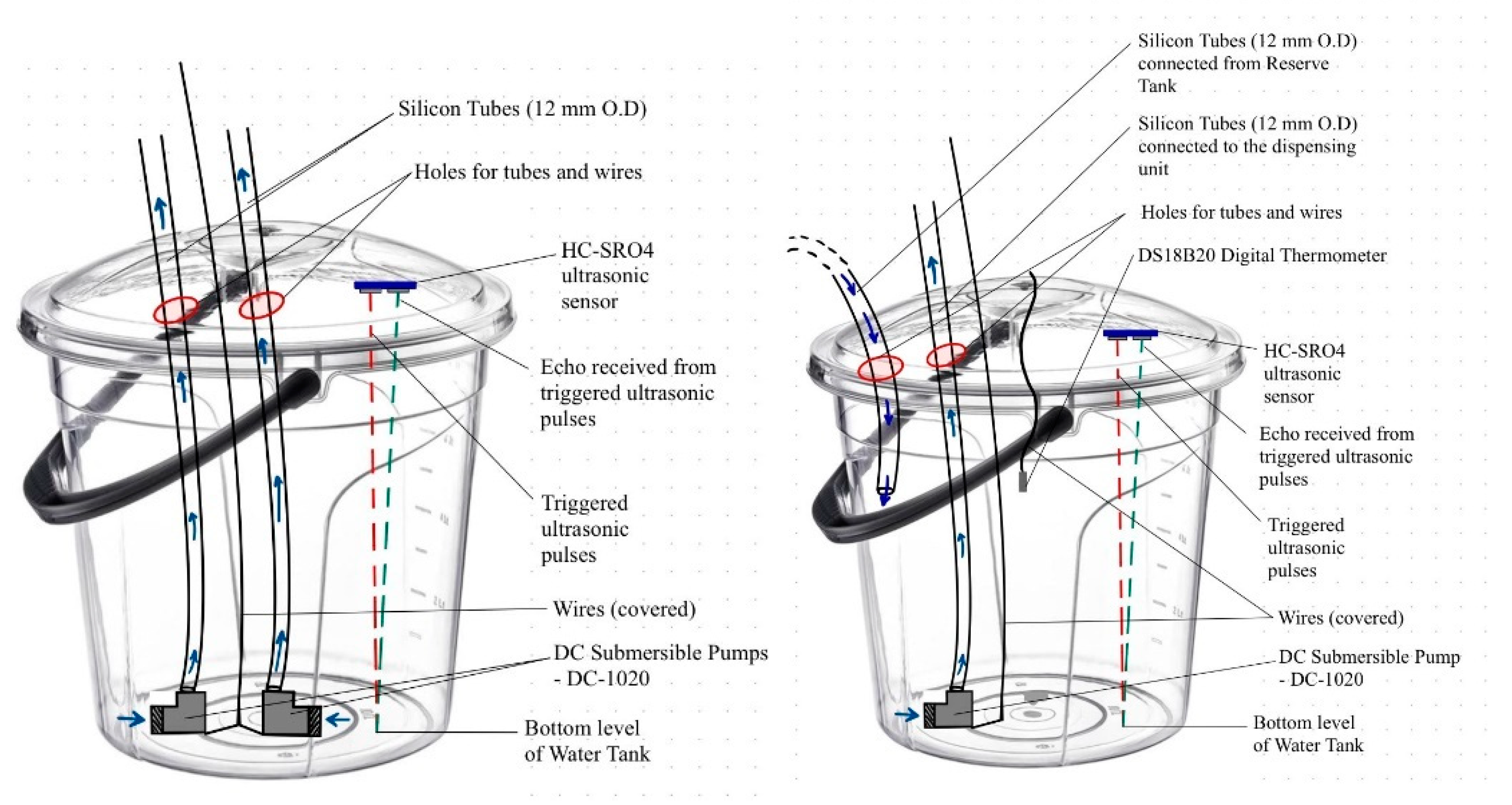
4.4. Water Level Monitoring System

In this section, the placement of components of the water level monitoring system will be covered, together with brief information about how the ultrasonic sensor works.
In the assembly of components required for the water level monitoring system on the large reserve tank, the HC-SR04 ultrasonic sensor is hot-glued on the lid facing the bottom of the tank. The two DC 1020 submersible water pumps are then placed inside with the silicon tubes attached. Holes are then drilled on the lid of the reserve tank for the silicon tubes and the wire as an exit way from the tank to be connected to other tanks and relays for power. To eradicate the exposure of wire in the drinking water, the wires coming out of the submersible water tanks are covered by silicon tubing and sealed until they reach the outside of the tank. Most importantly, the HC-SR04 ultrasonic sensor must be fixed in a location such that it is not blocked by the three silicon tubes, as it might cause inaccurate distance readings. As they are installed in a secure manner that prevents any movement after the lid is closed, vendors should properly close the lid every time they perform a refill. The assembly of the components required for the water level monitoring system on the other two smaller tanks is like that of the reserve tank when it comes to the ultrasonic sensors and the number of holes drilled on the lid. However, instead of two DC-1020 pumps, there will only be one in each tank to pump to the dispenser unit. Also, one silicon tube will be slotted in instead of coming out, as does the one in the reserve tank, as it functions as a way for water to flow into the tank to top itself up. Additionally, these tanks will have DS18B20 digital thermometers to measure the temperature of the water in the tank and display it for those using it. Figure 5 shows the sketch drawing of the tanks.
As shown in Figure 6a, the operation starts with the interactive screen asking the user to place their NRIC card on the RFID scanner. When a wrong card is placed, the LCD screen shows “Access Denied!” followed by a delay of 5 s, before proceeding back to the previous screen, asking the user to place their NRIC card on the RFID scanner. Once the correct card is detected, the interactive screen shows “Access Granted” for 5 s, and proceeds to display 2 options: A—Warm Water and B—Normal Water. The user will have to press either A or B, followed by the * key, to confirm selection. Any other keys pressed will result in the screen showing “Invalid Option! Try Again!!!” for 5 s, before returning to the previous selection screen of two options. The pseudo-code for Figure 6a is shown in italics below:
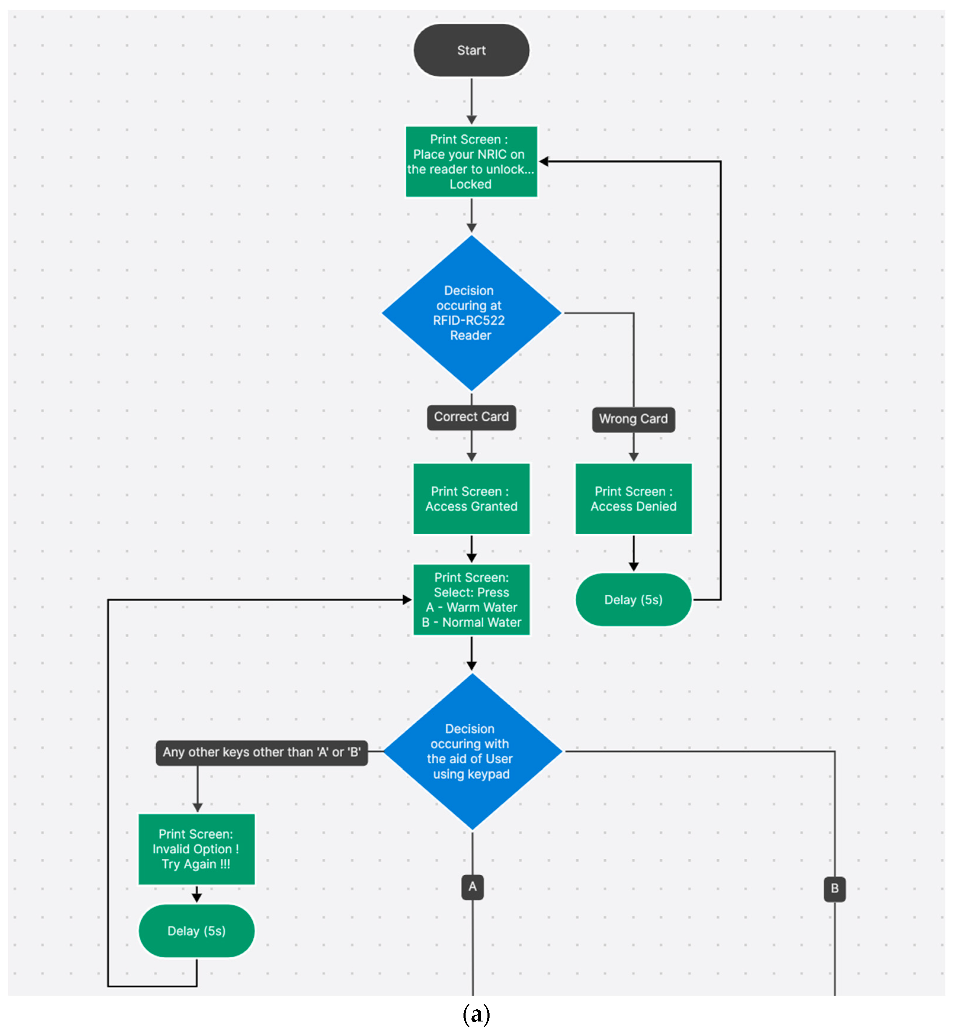
1. Start
2. Display “Place NRIC Card on RFID Scanner”
3. Wait for NRIC Card to be placed on RFID Scanner
4. If NRIC Card detected
    5. Display “Access Granted” for 5 s
    6. Display “Select Option: A—Warm Water, B—Normal Water”
    7. Wait for user input
    8. If user input is ‘A’ or ‘B’
        9. Wait for user to press ‘*’
        10. If user presses ‘*’
            11. Dispense selected water (Warm Water or Normal Water)
        12. Else
            13. Display “Invalid Option! Try Again!!!” for 5 s
            14. Go to step 6
    15. Else
        16. Display “Invalid Option! Try Again!!!” for 5 s
        17. Go to step 6
18. Else
    19. Display “Access Denied!” for 5 s
    20. Go to step 2
21. End
As shown in Figure 6b, if option A is selected, the screen will change to show that option A is selected, followed by asking the user to type a range between 001 to 999 mL followed by the * key to confirm. Upon pressing the * key, the chosen amount will be shown on the screen. If the chosen amount is within the range of 250 to 999, the screen will display “Place the Bottle on the Dispenser”. If the chosen amount is not within the range of 250 to 999, the LCD Screen will display “Invalid entry! Key Within Range! 250~950 mL”. If the chosen amount is within range and the bottle is detected by the infrared sensor, the screen will display “Dispensing” and show the amount dispensing on the screen with the help of the water flow sensor 1 and 12V solenoid 1 and the dedicated water pump 1 chosen by the user. Once the operation is complete, the LCD Screen will display “Completed!” and the end sequence will begin. If the chosen amount is within range and the bottle is not detected during operation, the dispensing operation will cease immediately, and the LCD screen will display “Bottle Not Detected! Pls Place Bottle!” and return to check the infrared sensor for bottle detection. The pseudo-code for Figure 6b is shown in italics below:
1. Start
2. If Option A is selected
    3. Display “Option A Selected”
    4. Display “Enter amount (001–999 mL) followed by ‘*’ to confirm:”
    5. Wait for user input
    6. If user input is within range 001–999
        7. If user presses ‘*’
            8. Display chosen amount on screen
            9. If chosen amount is within range 250–999
                10. Display “Place the bottle on the dispenser”
                11. Wait for bottle detection by infrared sensor
                12. If bottle detected
                    13. Display “Dispensing” on screen
                    14. Dispense water using water flow sensor 1, solenoid 1, and water pump 1
                    15. Display amount dispensing on screen
                    16. If dispensing complete
                        17. Display “Completed!”
                        18. End sequence
                    19. Else
                        20. Display “Bottle not detected! Pls Place Bottle!”
                        21. Go to step 11
            22. Else
                23. Display “Invalid entry! Key Within Range! 250~999 mL”
                24. Go to step 4
        25. Else
            26. Go to step 4
    27. Else
        28. Display “Invalid entry! Key Within Range! 001~999 mL”
        29. Go to step 4
30. End
As shown in Figure 6c, if option B is selected, the screen will change to show that option B is selected, followed by asking the user to type a range between 001 to 999 mL followed by the * key to confirm. Upon pressing the * key, the chosen amount will be shown on the screen. If the chosen amount is within the range of 250 to 999, the screen will display “Place the Bottle on the Dispenser”. If the chosen amount is not within the range of 250 to 999, the LCD Screen will display “Invalid entry! Key Within Range! 250~950 mL”. If the chosen amount is within range and the bottle is detected by the infrared sensor, the screen will display dispensing and show the amount dispensing on the screen, with the help of the water flow sensor 2 and 12 V solenoid 2 and the dedicated water pump 2 chosen by the user. Once the operation is complete, the LCD screen will display “Completed!” and begin the end sequence. If the chosen amount is within range and the bottle is not detected during operation, the dispensing operation will cease immediately, and the LCD screen will display “Bottle Not Detected! Pls Place Bottle!” and return to check the infrared sensor for bottle detection. The pseudo-code for Figure 6c is shown in italics below:
1. Start
2. If Option B is selected
    3. Display “Option B Selected”
    4. Display “Enter amount (001–999 mL) followed by ‘*’ to confirm:”
    5. Wait for user input
    6. If user input is within range 001–999
        7. If user presses ‘*’
            8. Display chosen amount on screen
            9. If chosen amount is within range 250–999
                10. Display “Place the bottle on the dispenser”
                11. Wait for bottle detection by infrared sensor
                12. If bottle detected
                    13. Display “Dispensing” on screen
                    14. Dispense water using water flow sensor 2, solenoid 2, and water pump 2
                    15. Display amount dispensing on screen
                    16. If dispensing complete
                        17. Display “Completed!”
                        18. End sequence
                    19. Else
                        20. Display “Bottle not detected! Pls Place Bottle!”
                        21. Go to step 11
            22. Else
                23. Display “Invalid entry! Key Within Range! 250~999 mL”
                24. Go to step 4
        25. Else
            26. Go to step 4
    27. Else
        28. Display “Invalid entry! Key Within Range! 001~999 mL”
        29. Go to step 4
30. End
As shown in Figure 7, after each set of dispensing, ultrasonic sensors placed on the lid of both Tank 1 (Warm Water) and Tank 2 (Normal Water) will check its water level. If any of the tanks’ water levels have been lowered, it will signal the mega board to trigger the specific pump at the reserve tank to pump water until the water level has reached its targeted water line and stop the water pump. The ultrasonic sensor on the lid of the reserve tank will measure the water level and indicate on a smaller LCD screen when the vendor must come and make a refill. The messages on the smaller LCD screen will be either of the following: (1) “Water Tank Full”, (2) “Water Tank Above 50%”, (3) “Water Tank Below 50%”, (4) “Water Tank Critically Low, Pls Replace Tank”. The pseudo-code for Figure 7 is shown in italics below:
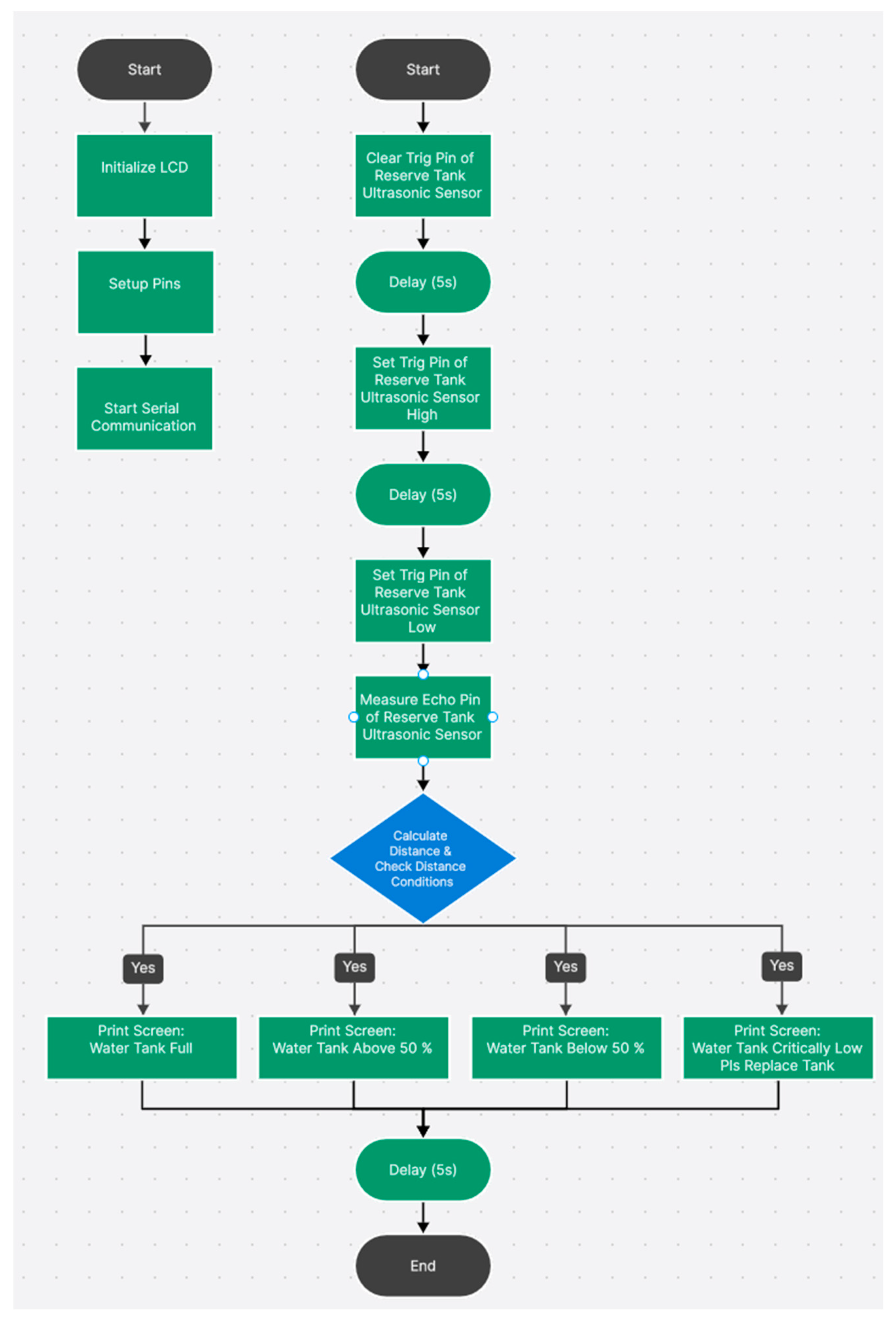
1. Start
2. After each dispensing operation
    3. Check water level in Tank 1 (Warm Water) using ultrasonic sensor
    4. If water level is lowered
        5. Signal Mega Board to trigger specific pump at Reserve Tank
        6. Pump water until water level reaches targeted line
        7. Stop water pump
    8. Check water level in Tank 2 (Normal Water) using ultrasonic sensor
    9. If water level is lowered
        10. Signal Mega Board to trigger specific pump at Reserve Tank
        11. Pump water until water level reaches targeted line
        12. Stop water pump
13. Measure water level in Reserve Tank using ultrasonic sensor
14. If water level is full
    15. Display “Water Tank Full” on smaller LCD Screen
16. Else if water level is above 50%
    17. Display “Water Tank Above 50%” on smaller LCD Screen
18. Else if water level is below 50%
    19. Display “Water Tank Below 50%” on smaller LCD Screen
20. Else
    21. Display “Water Tank Critically Low, Pls Replace Tank” on smaller LCD Screen
22. End

5. Result and Conclusions

After the design and fabrication of the entire prototype as shown in Figure 8, the Smart Water ATM with a bottle dispenser prototype is ready for testing. Two power supply sockets are needed to power this prototype.
In conclusion, the Smart Water ATM with a bottle dispenser prototype is considered a success in terms of achieving the project aim of creating a semi-automated Smart Water ATM that encourages users to drink and carry a water bottle in places where water dispensers are needed temporarily without relying on any water lines. Our proposed work incorporated several sensors, which enhance its functionality compared to conventional water dispensers. Bottle Detection IR Sensor—The Smart Water ATM only dispenses if it detects a bottle. This prevents unnecessary spilling, unlike conventional water dispensers. Temperature Sensors—The temperature sensors measure and display the temperature of the warm water tank and the normal room temperature water, unlike the conventional water dispensers where no temperatures will be displayed. Water Flow Sensor—The water flow sensor aids in measuring the amount of water being dispensed to dispense specific quantities of water in an automated way, unlike the conventional water dispensers that require manual dispensing.
If a user were to actively use the Smart Water ATM with a water bottle, the user would not need to buy a mineral water bottle from other shops or vending machines to quench their thirst. This means the need for mineral water in new plastic bottles will be lowered, which can help reduce the production of plastic bottles. If this movement made sure everyone traveled around carrying a personal water bottle along with them, they could even buy drinks other than mineral water by just refilling their water bottles directly. This means the production of consumer plastic bottles will be greatly reduced, contributing to sustainability efforts.
The project scopes are also achieved as the built prototype requires the users to key in the amount of water required to operate, which can be 250 mL or 500 mL, but not more than 999 mL. Also, there is a separate LCD screen for vendors to see the water level of the water in the reserve tank to see if they need to refill. For the next phase of this project, this prototype is planned to be tested on selected groups of participants such as on a specific level of an office building with the staff testing the operation and giving feedback. In the meantime, a mobile application can be planned to be developed to store the data of the user’s water consumption details, as well as reminders if they consume less water than their targeted water intake. The mobile application will then be introduced to the targeted participants linked with their office tags as RFID Tags. After 3 months of testing with the mobile application, a survey of the selected group of participants will be conducted to see what can be improved on the prototype usage and mobile application usage. If considered to be successful, a better and long-lasting variation will be built to be implemented at MRT stations and public places. The appendix is uploaded to Github, which can be found here: https://github.com/clkok1/appendix.git (accessed on 1 July 2023).

6. Future Work

This prototype holds potential for future enhancements, particularly in its ability to connect directly to Wi-Fi for seamless data access and updates on users’ smartphones. Rather than creating a new standalone mobile app, a partnership with established health monitoring platforms such as ‘Health Hub’ is preferable. In Singapore, where many rely on ‘Health Hub’ for managing appointments, accessing lab reports, and making payments within government-supported healthcare facilities, integrating water intake monitoring into this platform would enhance user convenience. This collaboration would streamline the user experience, as individuals would not need to install an additional app solely for water monitoring. Instead, they could effortlessly track their water intake alongside other health-related activities, promoting comprehensive wellness management.

Author Contributions

Conceptualization, Supervision, Data Curation, and Investigation, Y.Y.K.; Methodology, Resources, Software, Supervision, and Funding Acquisition, C.L.K.; Visualization, Methodology, and Formal Analysis, N.I.; Supervision, Resources, Funding Acquisition, and Project Administration, C.G.L. All authors have read and agreed to the published version of the manuscript.

Funding

This research received no external funding.

Data Availability Statement

The data presented in this study are available on request from the corresponding author. Unavailable due to privacy.

Acknowledgments

The authors would like to extend their appreciation to the University of Newcastle, Australia, for supporting the project.

Conflicts of Interest

The authors declare no conflicts of interest.

References

  1. Toh, C.M.; Cutter, J.; Chew, S.K. School based intervention has reduced obesity in Singapore. BMJ 2002, 324, 427. [Google Scholar] [CrossRef] [PubMed]
  2. Gunasinghe, A.; Tharmaseelan, J. Smart Water Dispenser. Int. J. Innov. Sci. Res. Technol. 2019, 4, 365–368. Available online: https://www.researchgate.net/publication/348832527_Smart_Water_Dispenser (accessed on 8 January 2024).
  3. Nag, A.; Nag, S. Smart Water Dispensing System: A New Approach of Monitoring, Controlling and Dispensing. Res. Appl. Emerg. Technol. 2020, 2, 5–13. [Google Scholar]
  4. Mujawar, S.; Gawade, S.; Shinde, M.; Udage, K.; Bhandari, M. RFID Card and Coin operated Water ATM. Open Access Int. J. Sci. Eng. 2020, 5, 4–6. Available online: http://oaijse.com/VolumeArticles/FullTextPDF/450_1.RFID_CARD_AND_COIN_OPERATED_WATER_ATM.pdf (accessed on 13 December 2023).
  5. Singh, P.; Lohani, M.K.; Nagarkoti, R.; Chakrabarti, S.; Karandikar, P.B. Development of Secure Integrated Water ATM as a smart system. In Proceedings of the 2021 International Conference on Artificial Intelligence and Smart Systems (ICAIS), Coimbatore, India, 25–27 March 2021. [Google Scholar] [CrossRef]
  6. Wahyuni, R.; Sentana, J.T.; Muhardi, M.; Irawan, Y. Water level control monitoring based on Arduino Uno R3 Atmega 238P using LM016L LCD at Stmik Hang Tuah Pekanbaru. J. Robot. Control. (JRC) 2021, 2, 265–269. [Google Scholar] [CrossRef]
  7. Anuradha, T.; Jadhav, S.; Mahamani, S. Smart water dispenser and monitoring water level in IOT and Android Environment. Int. J. Comput. Sci. Eng. 2019, 7, 810–814. [Google Scholar] [CrossRef]
  8. Syed Haidzir, S.H.H.; Hisham, O.A.H.; Omar, M. Smart Water Dispenser Monitoring System. In Proceedings of the International Jasin Multimedia & Computer Science Invention & Innovation Exhibition, Melaka, Malaysia, 17–28 February 2020; pp. 32–35. [Google Scholar]
  9. Tahir, M. Measuring Water Flow Rate and Volume Using Arduino and Flow Sensor; Department of Irrigation & Drainage Faculty of Agricultural Engineering: Faisalabad, Pakistan, 2021. [Google Scholar]
  10. Sarkar, A. Smart technology to serve urban poor: A case study of water ATMs in a Nairobi slum. Water Util. J. 2019, 22, 1–12. [Google Scholar]
  11. Kumar, A. Water ATMs of Indian Railways: Causing a Silent Revolution. Vikalpa 2018, 43, 106–114. [Google Scholar] [CrossRef]
  12. Schmidt, J.J. Pop-up infrastructure: Water ATMs and new delivery networks in India. Water Altern. 2020, 13, 119–140. [Google Scholar]
  13. Amankwaa, G.; Heeks, R.; Browne, A.L. Water ATMs and access to water: Digitalisation of off-grid water infrastructure in peri-urban Ghana. Water Altern. 2022, 15, 733–753. [Google Scholar]
  14. Jovanov, E.; Nallathimmareddygari, V.R.; Pryor, J. SmartStuff: A Case Study of a Smart Water Bottle. In Proceedings of the 38th Annual International Conference of the IEEE Engineering in Medicine and Biology Society, Orlando, FL, USA, 16–20 August 2016; pp. 6307–6310. [Google Scholar]
Figure 1. POU water cooler and dispenser at Changi Airport (Left); Water dispenser found in West Coast Park, Singapore (Right).
Electronics 13 01657 g001
Figure 2. Three-dimensional cuboid structure—after final door attachments.
Electronics 13 01657 g002
Figure 3. Assembled 3D-printed water dispenser unit.
Electronics 13 01657 g003
Figure 4. Wiring schematics for Arduino board and its components.
Electronics 13 01657 g004
Figure 5. Sketch drawing of assembled components on the reserve tank (left) and normal and warm water tanks (right).
Electronics 13 01657 g005
Figure 6. (a) Progam Flowchart 1/3. (b) Progam Flowchart 2/3 (Outcome A). (c) Progam Flowchart 3/3 (Outcome B).
Electronics 13 01657 g006aElectronics 13 01657 g006bElectronics 13 01657 g006c
Figure 7. Water level monitoring flowchart for Uno board.
Electronics 13 01657 g007
Figure 8. Closed isometric view of the prototype (left). Open isometric view of the prototype (right).
Electronics 13 01657 g008
Disclaimer/Publisher’s Note: The statements, opinions and data contained in all publications are solely those of the individual author(s) and contributor(s) and not of MDPI and/or the editor(s). MDPI and/or the editor(s) disclaim responsibility for any injury to people or property resulting from any ideas, methods, instructions or products referred to in the content.

