1. Introduction
As the global population ages, the number of disabled and semi-disabled people shows an increasing tendency [
1]. In the daily care of this population, transferring is the most physically demanding task for caregivers [
2], such as transferring a cared-for person from the bedroom to the bathroom. In order to reduce the burden of caregivers, many transfer nursing devices have been invented, such as RI-MAN [
3], piggyback transfer robot [
4], and so on. However, these transfer devices have comfort-related problems. For example, due to different physical characteristics of the cared-for persons, different degrees of force concentration during the human–robot interaction process can be produced, which reduces the comfort feeling of cared-for persons. To reduce the force concentration during the use of the transfer robot and improve its comfort, this paper innovatively installs an array of double wedge-shaped airbags at the human–robot interaction position (robot end-effector) and controls the internal pressure/height difference of the airbag array [
5]. This requires the experimental study and establishment of an accurate stiffness analysis model of the double wedge-shaped airbag.
Currently, there is a limited amount of research activities on modeling the mechanical properties of airbags. In the modeling of hyperelastic bodies such as airbags and air springs, the focus has been on theoretical models of airbags and the analyses of stiffness properties of air springs. Regarding airbag research, Hu [
6] developed an airbag inflation control model based on gas volume flow rate to simulate inflation and leakage, and then simulated airbags based on the finite element method. Zhang et al. [
7] proposed a theoretical model for airbag design and optimization, based on the momentum theorem and ideal gas equation of state for airbag parameters and occupant relations. Cao et al. [
8] studied the static performance of airbags in zero stress, initial, and loaded states, respectively, and performed finite element simulations. Yang et al. [
9] used MADYMO to establish the airbag model and verified the accuracy of the airbag model based on finite element simulations and experimental comparisons. Zhou et al. [
10] verified the feasibility of current airbag applications in terms of stiffness and mechanical properties of the airbag. The work mentioned above on the theoretical mechanical models and simulations of airbag construction and design accuracy has been carried out. However, there is still a lack of research and analysis on fitting models to the stiffness parameters of airbags.
Moreover, for air spring research, Li et al. [
11,
12] established a theoretical mechanical model for transverse and longitudinal stiffness of an oblong sac vibration isolator and experimentally verified its transverse and longitudinal static stiffness. Yin et al. [
13] developed a parametric model for the structure of sac air springs based on linear elasticity, Coulomb friction, and fractional derivative Maxwell’s model. A unified model for vertical stiffness of the sac air spring was developed based on the structural parameters and mechanical model of the rubber bag. Wu et al. [
14] developed a dynamic stiffness model for air springs based on equivalent damping and hysteresis properties and presented a general method to identify key nonlinear parameters in the model, such as effective area, equivalent stiffness, airbag stiffness, and equivalent damping. Cheng et al. [
15] derived expressions for stiffness properties including the gap coefficient based on elastic thin-shell theory and presented a method for calculating the stiffness properties of diaphragm-type airbag oscillators. Based on non-moment theory of elastic thin shell, Gu et al. [
16] established the equilibrium equations and boundary conditions of the airbag and derived the equations for the internal forces in the latitudinal and longitudinal directions of the airbag. In summary, theoretical models for transverse and longitudinal stiffness of air springs and identification methods for stiffness parameters have made significant contributions, but the analysis of the modulated properties of stiffness variation in airbags has not been fully investigated.
To address this problem, this paper studies a fitted model for the stiffness parameters of a single airbag applied onto the nursing transfer robot, performs a fitting analysis, and establishes a mapping between external load and displacement. The logical structure of the paper is as follows.
Section 2 details the construction of the array of double wedge-shaped airbags for the end-effector of nursing transfer robot, the airbag stiffness experiment platform, planning and designing the scheme for mechanical parameters of the single airbag stiffness, and defining the test range for external load and gas mass.
Section 3 constructs a CSAPSO-BP neural network fitting model for the mechanical parameters of the wedge-shaped airbag, obtaining fit relations for external loads and displacements at different gas masses.
Section 4 divides the variance law of airbag stiffness into three phases based on the characteristics of the fitted curves and analyzes the causes for the characteristic changes in stiffness curves during these three phases. Finally,
Section 5 presents conclusions of the study.
2. Test Method for Mechanical Parameters of Robot End Airbag
2.1. Working Principle of End Airbags of Nursing Transfer Robot
With a piggyback transfer robot being the example,
Figure 1 illustrates the working principle of the nursing transfer robot: the robot mimics the movements of a person carrying a person to get cared-for person to destination [
17]. During carrying, the chest of the cared-for person is always in contact with the array of airbags on the robot’s end-effector. From a top view, the array of airbags is composed of square airbags and wedge-shaped airbags that are fitted together. The square airbags are situated on both sides below the human chest, while the wedge-shaped airbag is located beneath the human chest. Each airbag is equipped with a built-in pressure sensor that continuously monitors the airbag’s internal pressure. The airbags are inflated and deflated based on a computer-controlled program, allowing for differential control of the stiffness and height of each airbag. This allows the airbag array can be adapted to the cared-for person with different physical characteristics, minimizing force concentration during human–robot interaction and improving human comfort.
2.2. Construction of Robot End Airbag Test Platform
Figure 2 depicts the test platform for the end airbag of nursing transfer robot, which includes a universal material test machine, data acquisition system, double wedge-shaped airbag, airbag control system, gas mass flow meter, and air pump. The air pump serves as the air source for inflating airbags, while the control system enables the inflation and deflation of each airbag. The airbag mechanical parameters are evaluated by using the universal material test machine, while the data acquisition system is used to obtain mechanical parameters associated with airbag stiffness.
2.3. Mechanical Parameters Test Scheme of Robot End Airbag
The double wedge-shaped airbag is manufactured by heat sealing technology from 840D nylon composite thermoplastic polyurethane elastomer (TPU) material with a density of 1.15 × 10⁻⁶ kg/mm3 and a thickness of 0.2 mm. It has a long side of 250 mm, a short side of 100 mm, a width of 100 mm, and a maximum height of 150 mm when filled with gas.
Before conducting the mechanical parameter tests, the first step is to determine the range of tests for the airbag gas mass and external load. The gas mass flow meter is used to measure the airbag’s gas mass (the product of cumulative gas flow rate and density). The external load test range is dependent on the adult body weight and the number of airbags being directly loaded. Since most adults weigh between 40–120 kg and eight wedge-shaped airbags are loaded directly onto human body, the external load range for each airbag falls within 11.53–34.58 N. To meet actual load requirements, the external load test range is enlarged by a factor of 1.5, resulting in a range of 0–51.88 N.
The mechanical test of the wedge-shaped airbag aims to evaluate its stiffness parameters such as gas mass, external load, original height of the airbag (vertical height under no-load), and displacement (the difference between original height and height under load), among others. It is vital to note that the tiny gas mass inside the airbag greatly impacts the accuracy of the mechanical parameter test results. Therefore, as a starting point, the gas mass just filling the airbag (1.29 g) is used as the initial experimental group, with an increment of 0.258 g per group and a maximum gas mass of 4.902 g.
Physical modeling based on theoretical methods is often utilized to model the stiffness properties of airbags for design optimization purposes, but the approach can be computationally challenging. In contrast, the BP neural network offers powerful input-output mapping capabilities, and then is well-suited for the airbag parameter fitting. However, BP networks can have slow convergence rates and may easily fall into local extreme values. Meanwhile, PSO algorithms possess fast convergence speeds and strong global optimization abilities for optimizing BP neural networks, but they lack dynamic speed regulation, which can impact network convergence and optimization. To address this, the inertia weights of the particle swarm optimization algorithm are dynamically adjusted by using the chaos theory to hasten convergence, while the probability and speed of the optimal algorithm are optimized by using simulated annealing to overcome slow convergence.
The CSAPSO-BP neural network combining the chaotic simulated annealing particle swarm algorithm with the BP neural network has good nonlinear modelling capability and can accurately fit the complex relationship between the displacement of the airbag and the external load. Using the input-output pairs of training samples, the network can automatically adjust the weights and biases to optimize the fitting effect of the model. Meanwhile, the CSAPSO-BP neural network shows strong robustness to outliers of the airbag mechanical parameters. Therefore, in this study, the CSAPSO-BP neural network is used for data fitting of airbag stiffness parameters (revealed in
Figure 3) across various working media qualities.
3. Analysis of CSAPSO-BP Neural Network Modeling
3.1. Principle of CSAPSO-BP Neural Network
This paper introduces a novel approach for tuning the BP neural network, which is a multilayer feed-forward neural network that utilizes the gradient descent algorithm with weights adjusted by backpropagation [
18]. Specifically, this method employs chaos theory to dynamically adjust the random numbers
by generating a chaotic sequence based on the Logistic model, as shown in Equation (1).
This study aims to optimize the kinematic behavior of the particle population in the algorithm. Specifically, the dynamic adjustment mechanism of the inertia weight is utilized to enable the particles to conduct a large range of global search in the initial stage of the algorithm and determine the approximate range of the optimal solution, as demonstrated in Equation (2). Moreover, a small inertia weight is used in the middle and later stages of the algorithm to search for optimal solution quickly and accurately.
where
and
are the maximum and minimum values of inertia weight and
t and
are the current and maximum iterations.
The global search power of the SA algorithm is greatly influenced by the initial temperature and the annealing rate. The proper setting of the initial temperature
can affect the fitness and acceptance probabilities, as shown in Equation (3).
Here, and represent the minimum and maximum objective function adaptation values of the initial particle swarm, respectively. is the initial acceptance probability, which is typically between 0.7 and 0.9. The annealing rate, on the other hand, impacts the depth of the local search, while the dynamic temperature decay coefficient is utilized to sense the local convergence rate.
Equation (4) illustrates the formula for calculating the temperature decay coefficient.
It includes and for the current and average fitness values, respectively. δ denotes the initial temperature attenuation coefficient, while is a random number with a Gaussian distribution, and represents the particle temperature before the iteration. The PSO algorithm is utilized to optimize the weights and thresholds of the system parameters, enhancing the generalization ability, and fitting accuracy of the BP network. Additionally, this study employs the CSAPSO algorithm to optimize the parameters of BP neural network. Furthermore, a wedge-shaped airbag stiffness mechanical parameter fitting model is established, and the training of the airbag stiffness mechanical parameter (external load–displacement) is conducted.
3.2. Simulation Experiment of CSAPSO-BP Neural Network Training and Testing
The mechanical parameter data of the wedge-shaped airbag stiffness is collected by external load and displacement testing, and a CSAPSO-BP neural network fitting model is trained and tested. As the training and testing procedures for fitting the wedge-shaped airbag stiffness parameter model in different experimental groups are similar, this study uses the experimental group (with a gas mass of 4.902 g) as an example to illustrate its training and testing procedure.
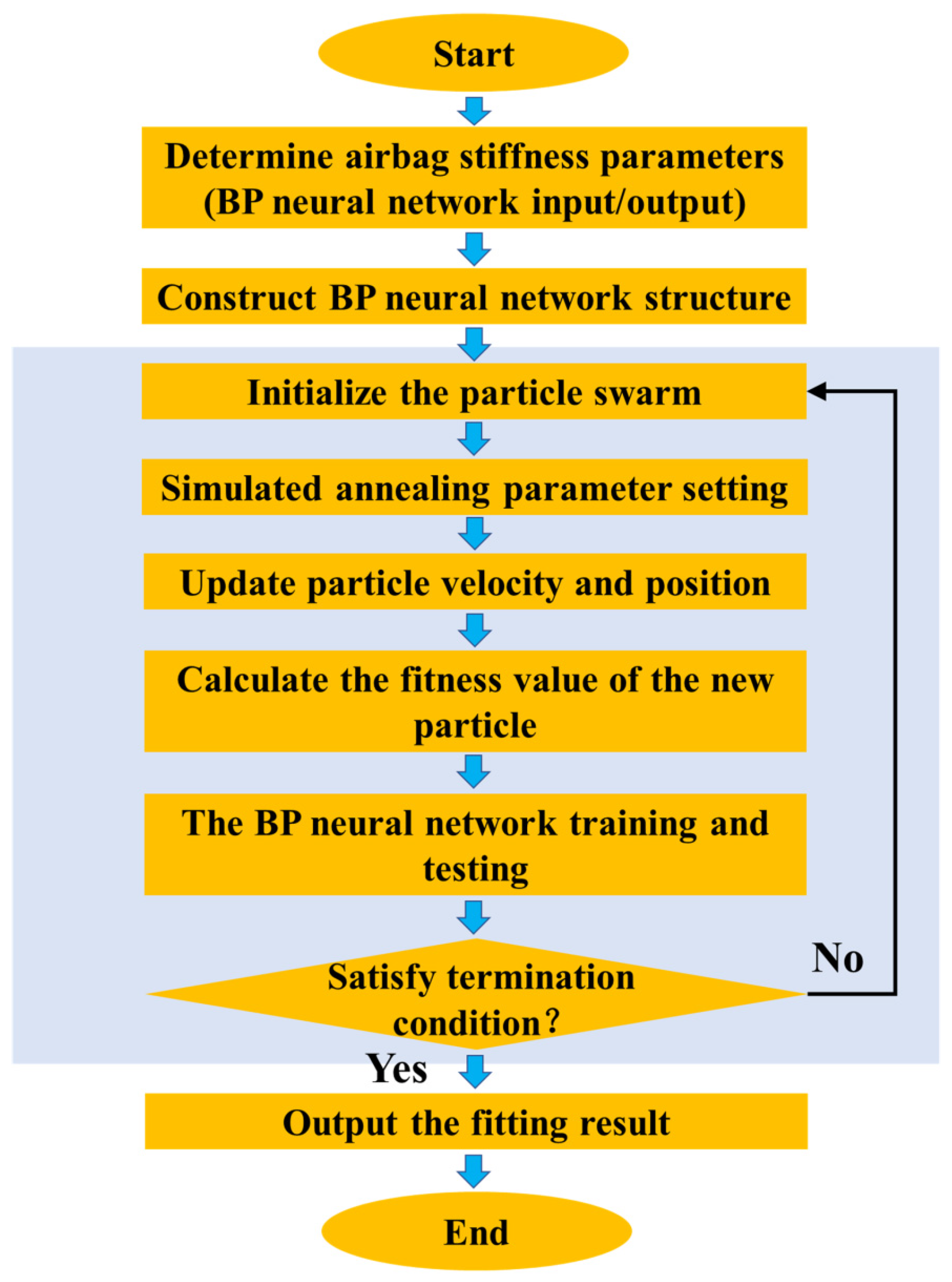
Figure 4 shows the training flowchart for the neural network fitting model of the mechanical parameters of the wedge-shaped airbag stiffness, where 70%, 15%, and 15% of the data are allocated to the training set, validation set, and test set, respectively.
The steps of CSAPSO-BP neural network training are as follows:
STEP I. Input and output of the neural network are utilized to determine the stiffness and mechanical parameters of the wedge-shaped airbag. The displacement is taken as the input, and the neural network fitting model is applied to determine the mechanical parameters of the wedge-shaped stiffness. The output of the fitted model corresponds to the external load.
STEP II. A BP neural network model is established to predict the wedge-shaped stiffness parameters. Based on the performance of the training sample, the number of hidden layer units is determined to be 10, the learning rate is set to 0.1, and the training error target is set to .
STEP III. PSO and parameter setting, particle number N = 20, learning factor , ,.
STEP IV. Simulated annealing parameter settings, , = 0.98, = 0.7.
STEP V. Update the velocity and position of the particle.
STEP VI. Calculate the fitness curve of the new particle.
STEP VII. The optimal threshold weights are obtained and assigned to the network for training and testing.
STEP.VIII Whether the stopping condition is satisfied. When the stopping condition is not satisfied, the particle swarm initialization is performed again.
STEP IX. The wedge-shaped airbag stiffness mechanical parameter fitting model is generated and the fit results are output.
The best training performance of the CSAPSO-BP neural network fitted model for the mechanical parameters of the wedge-shaped airbag stiffness is shown in
Figure 5. The training is stopped at the 89th iteration with a root mean squared error of 0.016025. To achieve the best fitting performance, the mean square error should be as small as possible, the test set error and the validation set error should have similar characteristics, and there should be no over-fitting phenomenon during the iteration process. Therefore, the fitting model reaches its best performance at the 83rd iteration.
Figure 6 depicts the regression diagram for the expected and predicted output of the training set, validation set, and test set of the CSAPSO-BP neural network fitting model for the mechanical parameters of the wedge-shaped airbag. This figure highlights the correlation between external load and predicted output. The data points for all datasets show a correlation close to 1, indicating a highly accurate and efficient modeling process for the fitted model.
3.3. Fitting Results of CSAPSO-BP Neural Network
Figure 7 presents the fitting diagram for the external load–displacement data. As seen in the figure, the fitting relation is linear, and the fitting equation is Equation (5).
Figure 7 shows the fitting diagram of external load–displacement data. As can be seen from the figure, the fit relation is linear and the fit equation is Equation (5).
where
represents displacement and
y indicates external load.
Figure 8 shows the residual diagram of the external load–displacement fitting of the wedge-shaped airbag. It is noteworthy that the maximum difference is 1.746 mm when
, and there are two peaks at −0.5592 mm and 0.6985 mm for
mm and
mm, respectively. The residual norm of this linear fit is 15.5187 mm.
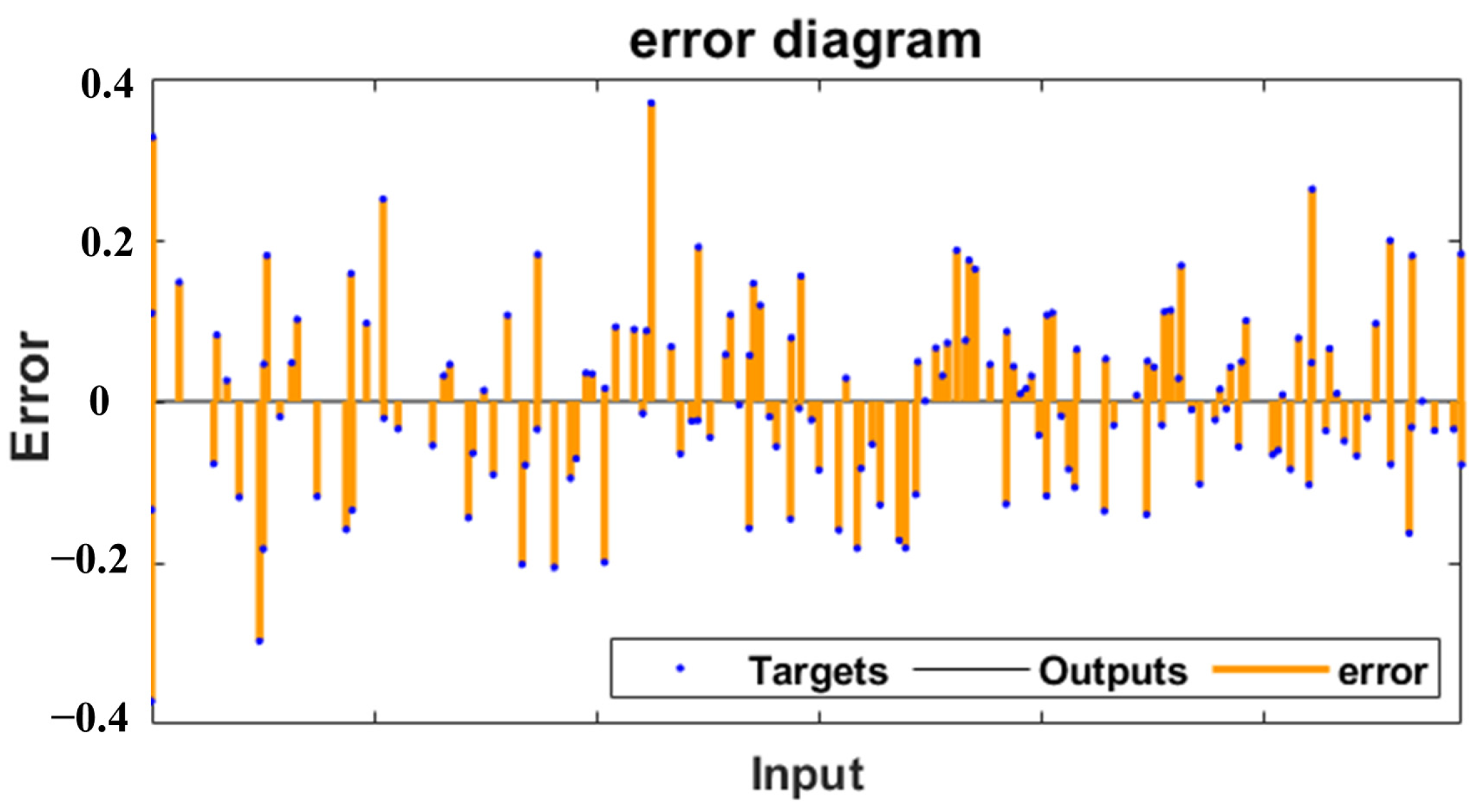
Figure 9 presents the error diagram of the fitting model. The error between the target value and the output values ranges between −0.4 and 0.4, indicating that the CSAPSO-BP neural network provides strong fit accuracy for the airbag mechanical parameter modeling.
4. Stiffness Analysis and Discussion of Airbag Test Model
The CSAPSO-BP neural network is utilized to establish a model for the mechanical parameters of the wedge-shaped airbag and fit the external load and displacement data for various gas masses. The fitting results reveals that the stiffness characteristics of the wedge-shaped airbag vary quadratically, linearly, and constantly as gas mass increases, implying that the change in wedge-shaped airbag stiffness can be divided into three stages. Airbag stiffness is influenced by gas mass, external load, temperature, and loading rate. The intention of the end-effector airbag is to assist cared-for person in comfort robot transferring. During the operation, the deformation speed of the airbag and molecular movement are moderate, and can be expressed as a variable index
N, where gas state transfer in the airbag constitutes an almost isothermal process (
N ≈ 1), airbag load is approximately static, and airbag stiffness is also static, excluding dynamic load conditions. Thus, this study only considers the effects of external load and gas mass on airbag stiffness.
Table 1 illustrates the fit function and stiffness for first-stage airbag parameters. The fitting function for the external load–displacement exhibits cubic characteristics, while the stiffness curve of the airbag displays quadratic characteristics.
Figure 10 displays the fitting diagram of the external load–displacement data of the wedge-shaped airbag in the first stage. It is evident from the figure that the rate of shift (curvature) of the fitted curve reduces with an increase in gas mass.
Figure 11 shows the variable stiffness of the wedge-shaped airbag in the first stage. It can be observed from the figure that the airbag stiffness is not constant, and its rate of change (curvature) increases as the gas mass rises, with the curve characteristics indicating a trend of linear transformation to quadratic power. The mechanism of airbag stiffness shift is explained by relevant theory and testing procedure. The double-layered wedge-shaped structure of the airbag is primarily influenced by the small caliber of the connecting part between its upper and lower layers, as well as the small angle of the wedge-shaped tip. As a result, the tension between the top and bottom surfaces is insufficient. When the internal gas volume is low, continuous loading of the airbag causes the internal pressure and gas density to increase, leading to gas diffusion and movement. This results in the variable stiffness of the wedge-shaped airbag, and ultimately the deformation of the airbag due to loading. These phenomena manifest as the lifting up of the wedge-shaped part and the uneven distribution of gas in the upper and lower airbags. Consequently, this phenomena during the robot carrying process are not conducive to controlling the stiffness and airbag height.
Table 2 displays the fit function and stiffness for the airbag-shaped parameters in the second stage. The external load–displacement fitting function is quadratic, and the airbag stiffness curve is linear in nature.
Figure 12 presents the curve fitting diagram of the external load and displacement in the second stage. It is observed that the shift rate (curvature) of the curve increases as the gas mass increases.
Figure 13 illustrates the stiffness variation of the wedge-shaped airbag in the second stage. It can be noticed that the stiffness of the airbag is variable and linearly increases with the increase of gas mass, transitioning from linear features to constant features. The reason for the variable stiffness of the wedge-shaped airbag is the same as described earlier. However, as the gas mass within the airbag increases, the wedge-shaped tip area of the airbag becomes more rigid and lifts, constrained by the volume and structural limitations of the airbag. This behavior of the airbag affects the comfort during the robot carrying process.
Table 3 presents the fit function and stiffness of the wedge-shaped airbag parameters in the third stage. The external load–displacement fitting function is linear, leading to a constant airbag stiffness.
Figure 14 displays the fitting diagram of the stiffness change of the wedge-shaped airbag in the third stage. Notably, the gas mass ranges from 2.838 g to 4.902 g. The airbag’s stiffness remains constant, and the fit function of the airbag stiffness and gas mass is quadratic. The change rate (curvature) of the airbag stiffness with an increase in the gas mass is fast at first and then slow, and then is fitting Equation (6).
The airbag stiffness in the third stage is characterized by being constant. The reason is that the airbag volume is fixed and there is no space for gas flow. The airbag becomes filled with gas, which supports the airbag pressure and results in a fixed stiffness. As the gas mass increases, the air molecules become further compressed, leading to changes in density and internal pressure. However, the gas mass supporting the airbag does not increase linearly. Therefore, a quadratic fitting function characterizes the relationship between airbag stiffness and gas mass in the third stage, with a curvature that increases initially and then decreases. In this stage, the wedge-shaped tip of the airbag increases in angular displacement, and overloading can cause it to sway left or right, adversely affecting both the cared-for person’s chest fit and airbag stiffness and height control.
Based on experiments and related theories, the stiffness characteristics of the airbag can be adjusted by controlling the total mass inflated inside the airbag, thereby improving comfort, and optimizing the individual control of the airbag. For example, in the transfer process in nursing homes, the ideal stiffness value of each care-receivers with different body types can be obtained based on the stiffness model of airbag, which can improve the comfort, promote the wide application of the piggyback transfer robot, and reduce the nursing pressure of the caregivers. In the rehabilitation process, the pressure distribution on the chest of the care-receiver can be controlled according to the stiffness model of the airbag, reducing the pressure in specific areas, and preventing the formation of pressure sores. To achieve better control, it is possible to optimize the structure of the double wedge-shaped airbag by shortening the length of the double-layered airbag’s wedge-shaped tip, replacing it with a curved edge, and improving communication between the upper and lower chambers.
5. Conclusions
In this study, we focused on the double wedge-shaped airbag mounted on the end-effector of nursing transfer robot and conducted mechanical tests to obtain airbag external load and displacement at various gas masses. A fitting model of airbag mechanical parameters was established using the CSAPSO-BP algorithm and the fitting analysis was carried out. We determined the evolution law of airbag stiffness and analyzed the reasons for its stiffness shift. The findings suggest that:
- (1)
The wedge-shaped airbag mechanical parameter fitting model based on the CSAPSO-BP algorithm is effective and reliable. On this basis, we obtained the load–displacement fitting relationship of the wedge-shaped airbag and provided a fitting expression for its stiffness.
- (2)
In the first stage of gas mass increase, airbag stiffness is variable and the fitting function has quadratic characteristics and shows a tendency to transition to a linear character. In the second stage, the airbag stiffness is variable and the fitting function has linear characteristics and shows a tendency to transition to a constant character. In the third stage, the airbag stiffness is fixed and its stiffness-gas mass curve is quadratic with a decreasing slope.
- (3)
The study recommends shortening the length of the double-layered airbag’s wedge-shaped tip, replace it with a curved edge, and improve communication between the upper and lower chambers.
This approach will lay a stronger foundation for optimizing airbag control and reducing force concentrations during human–robot interaction. However, there are certain improvements that need to be further investigated. Firstly, more training data can help improve the performance and generalization of the model. Although the dataset used in this paper can already satisfy the need to find the evolution laws of the airbag stiffness, trying to collect more sample data in future studies will help to improve the model accuracy. Secondly, trying to select other suitable features is more conducive to building an accurate stiffness model. By introducing additional parameters, such as area of pressure, the model ability to describe the airbag mechanical parameters can be increased.


