Article

Design and Analysis of an H-Type Pickup for Multi-Segment Wireless Power Transfer Systems

1
School of Electrical Engineering, Shandong University, Jinan 250061, China
2
Energy Research Institute, Shandong Academy of Sciences, Jinan 250014, China
*
Author to whom correspondence should be addressed.
These authors contributed equally to this work.
Electronics 2024, 13(6), 1125; https://doi.org/10.3390/electronics13061125
Submission received: 4 February 2024 / Revised: 9 March 2024 / Accepted: 16 March 2024 / Published: 19 March 2024
(This article belongs to the Special Issue Recent Research on Wireless Power Transfer Systems)

Abstract

:
To tackle the complex wireless power supply requirements in the Automated Material Handling System (AMHS) of semiconductor wafer factories, this paper presents a design method for a magnetic coupling mechanism based on a Multi-Segment Wireless Power Transfer (MSWPT) system for dynamic wireless power supply in segmented track configurations. Firstly, the track is approached using Inductive Power Transfer (IPT) technology combined with an LCC-S resonant structure transmitter (Tx). Following this, the feasibility of the H-type pickup is assessed through magnetic and electrical circuit analyses, which leads to the preliminary determination of the pickup dimensions by means of finite element magnetic and thermal simulations. Furthermore, an analysis of the mutual inductance drop is conducted under various track structure parameters during track crossing and curve negotiation operation conditions. Secondly, a dual-coil winding method is proposed to reduce the insulation stress on the PCB board. Additionally, a method for calculating the wire length and a design process for the overall parameters of the pickup are derived. Finally, two Txs and a 1.5 kW power receiver (Rx) were designed to verify the mutual inductance fall under the aforementioned conditions. During low-speed full-load operations, a constant-voltage output was achieved through the proposed dual-loop PI control strategy, thereby meeting the requirements for a constant-voltage output in industrial applications.

1. Introduction

Wireless Power Transfer (WPT), as a method of transferring energy from a power source to a load without direct electrical contact, offers unique advantages in a variety of fields such as industrial automation equipment [1,2,3], electric vehicles [4,5], implantable medical devices [6], and household appliances by avoiding the arc and wear caused by metal contact plugging and unplugging. In semiconductor wafer foundries, the Automatic Material Handling Systems (AMHSs) necessitate a complex production line within a dust-free cleanroom environment, creating a demand for a dust-free and efficient energy transfer solution. The Inductive Power Transfer (IPT) system, utilizing the principle of magnetic resonance, enables high-power supply without electrical connections. Recent advancements in power electronic control technologies and improvements in the performance of semiconductor power components and magnetic devices have brought their power and efficiency levels closer to those of traditional wired power supply methods. To solve the problems of mechanical wear and dust associated with wired power supply in wafer foundries, and to meet the requirements for high-precision unmanned cleanrooms, the Multi-Segment Wireless Power Transfer (MSWPT) system, a track-based power supply solution specifically designed for the Overhead Hoist Transport (OHT) systems within Automated Material Handling Systems (AMHS), is increasingly attracting attention and is the subject of ongoing research.
Current research on dynamic MSWPT systems primarily focuses on flat-coil coupling systems for electric vehicles. A novel modular DD coil structure, proposed in the literature [7], achieves minimal interaction, fault tolerance, and interoperability for wireless charging in electric vehicles. The concept of mutual inductance calculation coefficients, introduced in [8], guides the design of magnetic couplers for electric vehicles, and a prototype was developed for validation. While there is relatively less research on MSWPT systems suitable for semiconductor wafer foundries [9,10], steady progress has been observed in the research on coil and embedded magnetic core structures for both transmission and pickup sections [11]. However, the majority of current research is concentrated on flat-type [12] and omnidirectional WPTs [13,14], with limited studies on track-type transmitter (Tx) track systems and embedded magnetic core structures. The literature [15] presents the design of an underground E-type magnetic core structure achieving a 100 kW wireless power supply system with a 26 cm air gap. Additionally, the literature [16] describes the design of a buried S-type ultra-thin magnetic core for the wireless charging of roadway-powered electric vehicles (RPEVs), which has been successfully commercialized. The research documented in [17] involves the design of an I-shaped, small-scale, large air-gap WPT system, achieving a maximum power transfer of 27 kW. In [18], the authors introduced a simulator with a Tx-end buried I-shaped magnetic core and a DQ-phase receiver (Rx) structure capable of accurately simulating and testing a wide range of driving speeds and investigating the resonant current stress on the receiver end. Most of the above WPT systems were studied with flat-plate magnetic coupling mechanisms, while the development of the orbital wireless power supply originated at the University of Auckland, New Zealand [19] and has gradually been further developed and diversified by scholars and companies in various countries [20,21]. These scholars have made pivotal contributions to the industrial and industrial aspects of WPT, but little has been said about the design thinking of magnetically coupled mechanisms.
This paper presents the design and performance test results of an H-type magnetic core for a multi-segment track-based wireless power supply system. It includes mutual inductance drop simulation analyses for different operational conditions, followed by experimental validations. The main contributions of this paper are as follows: firstly, an analysis of the LCC-S circuit structure and the magnetic circuit structure of the H-type pickup is conducted based on the load power requirements, introducing a dual-coil winding structure to reduce voltage stress. Secondly, the paper analyzes mutual inductance drop scenarios in door-type track switching and sudden diverging junctions under different operating conditions. Thirdly, it examines the temperature distribution and loss components of the proposed magnetic coupling mechanism, providing a design process for the magnetic coupling mechanism. Finally, the paper presents the validation of the accuracy of the aforementioned analyses through experiments, the design of a buck–boost structure, and the incorporation of a dual-loop PI control to ensure the stability of the load voltage.

2. Analysis of Electrical and Magnetic Circuits

2.1. Multi-Tx LCC-S System Circuit Analysis

In semiconductor wafer foundries, due to the complex actual operation paths of OHT vehicles, such as during track switching, the Txs providing real-time power to OHT vehicles may not be singular. The equivalent circuit structure of the MSWPT system is shown in Figure 1. To facilitate the analysis of the transmission characteristics of MSWPT, the system is simplified into an LCC-S structure. This choice is based on the applicability of the constant-current characteristic of the transmitting coil and the constant-voltage characteristic of the load voltage within the OHT system. The main components are the equivalent DC voltage source V i n in the multi-Tx structure, the high-frequency inverter, and the LCC resonant cavity. U i n represents the input voltage of the resonant cavity, wherein L f , C f , and C P in the LCC resonant cavity are the resonant inductance and capacitance of the resonant compensation network, R p is the equivalent parasitic resistance of the Tx track, and L p is the Tx track coil. The Rx structure contains the S-topology resonant cavity, diode rectifier, and equivalent load R L , where L s in the S-resonant topology is the Rx coils, and C s , R s are the resonant compensation capacitance and equivalent parasitic resistance, respectively. According to Kirchhoff’s voltage law (KVL), we obtain the mutual inductance theoretical model of the MSWPT single-Tx and single-Rx systems.
j w L f + 1 j w C f 1 j w C f 0 1 j w C f 1 j w C f + 1 j w C p + j w L p + R p j w M 0 j w M 1 j w C s + j w L s + R s + R e q I f I p I s = U i n 0 0
From (1), in order to maximize the transmission capacity, the resonant conditions of the system are as shown in (2).
w 0 = 1 L f C f = 1 ( L p L f ) C p = 1 L s C s
where w 0 is the resonant frequency of the system.
Thus, the expression for the current in the track coil is given by the following:
I p = U i n j w 0 L f
From (3), it can be seen that the track current Ip at the transmitter side is only related to the series-compensated inductance L f . The constancy of the track current ensures the stability of the system’s power delivery. The output power expression of the system is given by the following:
P o u t = M 2 U i n 2 R L R s + R L 2 L f 2
From (4), the system output power and the mutual inductance between the coils of the WPT system are positively correlated. Therefore, considering how to increase the system’s mutual inductance and ensure the stability of the system’s mutual inductance becomes a measure of the MSWPT transmission capability.

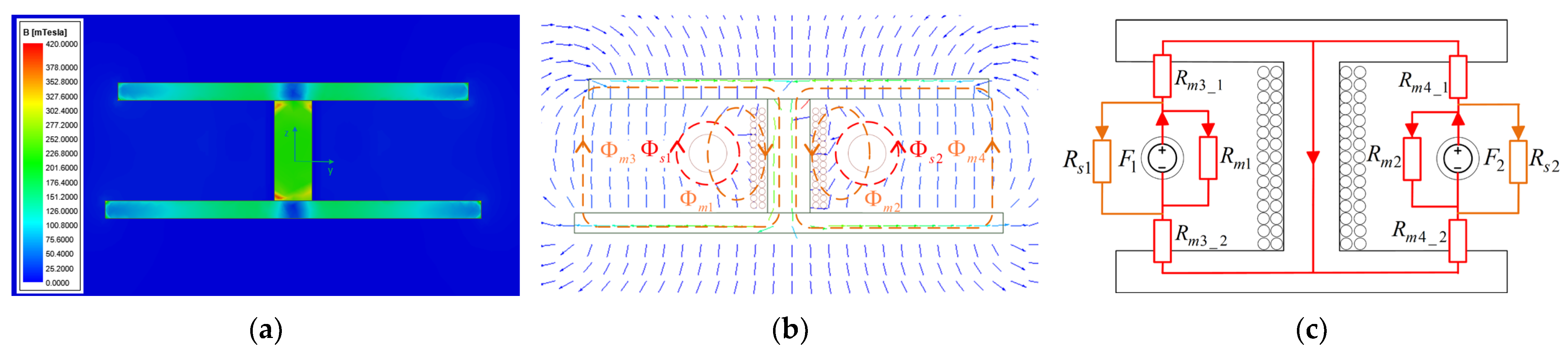
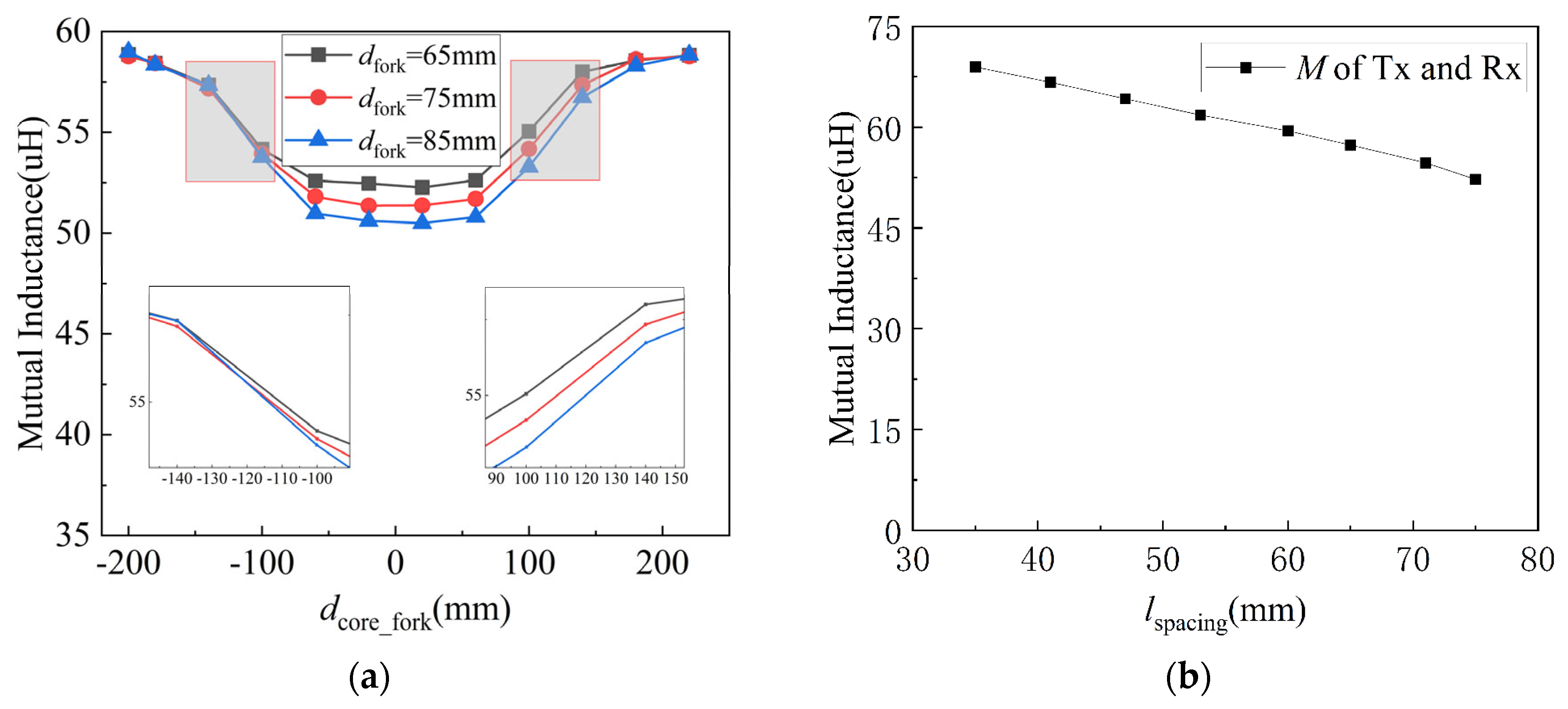
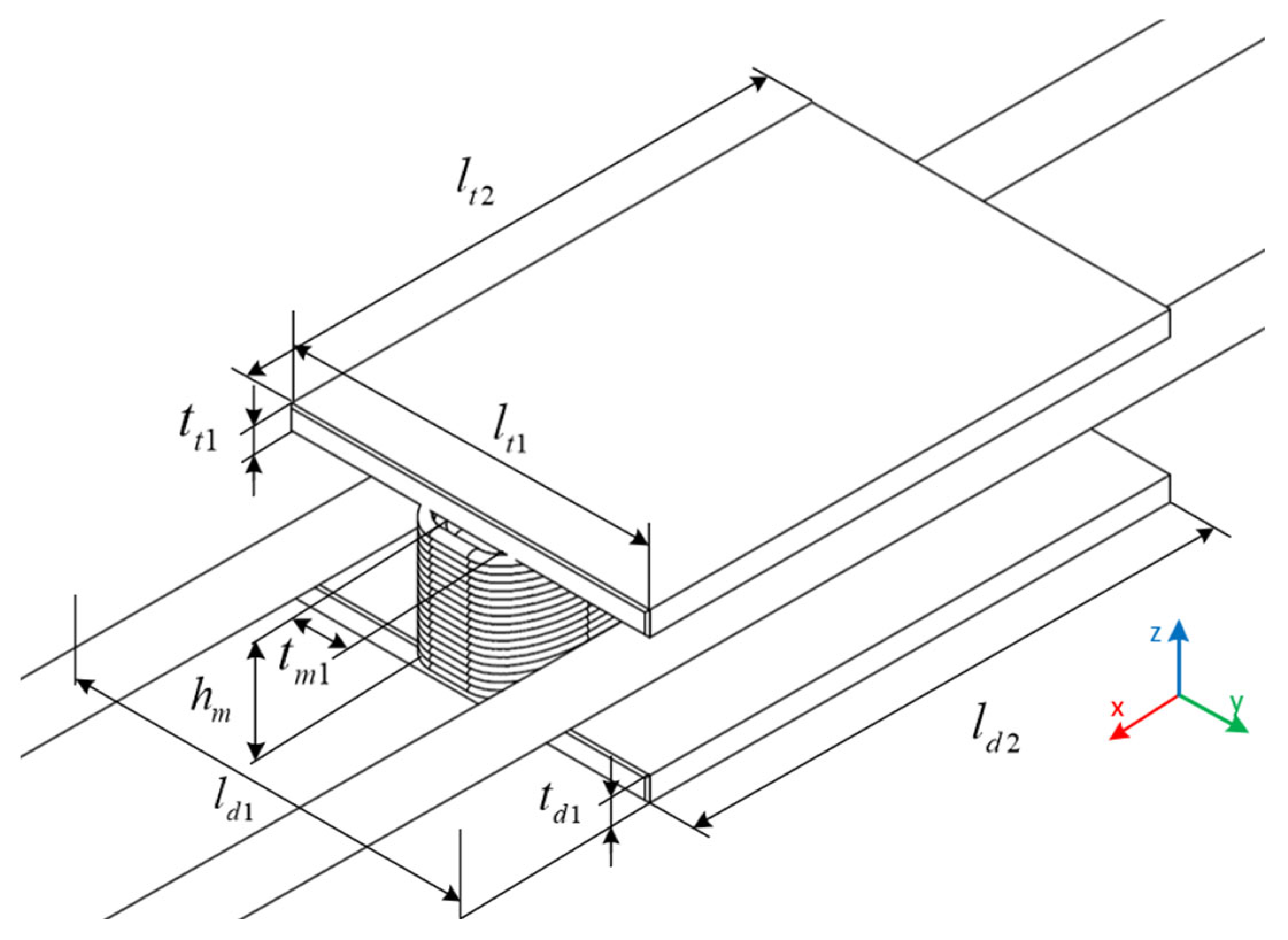
2.2. Magnetic Circuit Analysis of the Coupling Mechanism

In the loosely coupled structure of an H-type pickup, the magnetic pathway within the coupling mechanism is bifurcated into two distinct components: the core path and the air path. Owing to the significantly higher permeability of ferromagnetic materials compared to air, the magnetic resistance of the core is typically negligible in analyses. Understanding the magnetic pathway of the coupling mechanism is instrumental in informing the core structure design. By establishing a Maxwell model for the H-type magnetic core, we can delineate the distribution of magnetic induction intensity and ascertain the saturation level within the XOZ plane of the coupling mechanism. Core thickness parameters are strategically devised with reference to the core material’s saturation flux density, maximizing the core’s utilization. In this study, the core was constructed by splicing multiple core plates of PC-95 material, which maintains its good magnetic material properties at room temperature. The distribution of magnetic flux density, considering this as the minimal reference, is illustrated in Figure 2a. This depiction confirms that the core, in its entirety, does not reach saturation.
In the configuration between the H-pickup and the Tx track, two types of magnetic field regions can be identified based on their coupling characteristics: the self-coupling region and the mutual coupling region, as demonstrated in Figure 2b. To minimize skin and proximity effects in the wires within a high-frequency environment, both the Tx and Rx coils are wound with litz wire. As shown in Figure 2c, F 1 and F 2 denote the magnetic kinetic potential of each Tx track, respectively. For the equivalent magnetic circuit, the magnetic circuit is segmented into two self-coupling regions and three mutual coupling regions. The magnetoresistance of the self-coupling regions is marked as R s 1 and R s 2 , respectively, and that of the mutual coupling regions is marked as R m 1 , R m 2 , and R m 3 . Notably, R m 3 is further subdivided into several parts:
Φ s 1 = F 1 R s 1 Φ s 2 = F 2 R s 2 Φ m 1 = F 1 R m 1 Φ m 2 = F 2 R m 2 Φ m 3 = F 1 R m 3 _ 1 + R m 3 _ 2 Φ m 4 = F 2 R m 4 _ 1 + R m 4 _ 2
In (5), Φ s i and Φ m i , (i = 1, 2, 3, 4), denote the magnetic flux in the self-coupling and mutual coupling regions, respectively, and F is the magnetomotive force. The expression for the coupling coefficient between the Tx track and the H-type pickup is given by (6) the following:
k = Φ m 1 + Φ m 2 + Φ m 3 Φ s 1 + Φ s 2 + Φ m 1 + Φ m 2 + Φ m 3
To simplify the analysis, we consider the structure of the two ends of the H-type pickup to be symmetrical. Therefore, F 1 = F 2 , R s 1 = R s 2 , and R m 1 = R m 2 . The simplification is expressed as (7):
k = 1 1 + Λ s 1 / ( Λ m 1 + Λ m 3 + Λ m 4 )
where Λ s 1 represents the magnetic permeability in the self-coupling region, and Λ m i , (i−, 3, 4), represents the magnetic permeability in the mutual coupling region.
From (7), it becomes clear that when tailoring the core structure and dimensions for the coupling coefficient k pairs, reducing the permeability in the self-coupling region while increasing it in the mutual coupling region serves as an effective strategy to enhance the coupling coefficient. Prioritizing cost efficiency and ease of track transition, the H-type magnetic core is identified as the optimal pickup for OHT systems in wireless energy transmission.

2.3. Method of Double Coil Winding

To minimize insulation stress on the PCB’s main circuit, this study suggests employing a dual-segment coil winding oriented uniformly and paired with segmented resonant capacitors, as shown in Figure 3. Given that each coil in the dual-coil configuration has the same number of turns, denoted as N2, the voltage across the coils can be represented as follows:
u L s 1 = j w 0 M L s 1 U i n L f R L
From (8), it is evident that the coil voltage uLs1 is correlated with the coil’s self-inductance L s and mutual inductance M. Compared to a single-coil winding setup, the voltage calculation for a single coil involves the inductance parameter Ls. In a dual-coil winding configuration with two litz wires wound around the central column, the self-inductance of each coil is equivalent to that of a single-coil winding, as indicated in (8). In the dual-coil winding method, when integrated into the PCB, the insulation stress at the connection points is reduced to a quarter of that in the single-coil winding approach.
L s = L s 1 + L s 2 + 2 M s 1 _ s 2
where L s 1 and L s 2 denote the self-inductance of each coil in the bobbin winding, respectively. M s 1 _ s 2 is the mutual inductance between L s 1 and L s 2 . Thus, from (9), it can be deduced that Ls1Ls2Ls/4 when the numbers of turns of the two coils are equal in the dual-coil winding mode. Therefore, according to (8), the coil voltage is reduced to one-fourth of that of the single-coil winding configuration.
In WPT systems, the source of cost depends partly on the core and coil costs. To consider the manufacturing cost and conduction losses of individual pickups, the length of the pickup coils of a WPT system should be efficiently estimated. For a dual-coil winding configuration, the total coil length on a single pickup is determined in the following manner:
l w i n d i n g = 2 N l m 2 + l a m p l e + l s c a n t + Δ l
l a m p l e = π h 1 m D i = 1 N x 1 t m + ( i 1 2 ) D
l s c a n t = ( N N x h 1 m D ) π t m + ( N x 1 2 ) D
where l w i n d i n g , D , and Δ l are the required litz wire length of the coil, the diameter of the litz wire used, and the correction factor, respectively. l a m p l e , l s c a n t denote the length of the litz wire that is wound full of one layer of the column in the core and the length of the wire that is not full of the winding. N x denotes the total number of layers of the coil winding and the expression is given below:
N x = N D h 1 m
Integrating the aforementioned derivations, it becomes apparent that there is no substantial disparity in wire length between the dual-coil winding configuration and the usage of a single coil. The primary distinction resides in the fact that the dual-coil winding possesses four lead wires for connecting to the resonance compensation capacitor and the main circuit part of the PCB. Crucially, this dual-coil winding approach significantly mitigates the insulation stress on the PCB, thereby markedly reducing the likelihood of breakdown. These calculations offer a reliable reference for estimating the coil length in industrial manufacturing pickups, ensuring precision in practical applications.

3. Analysis of Track Switching Methods for OHT

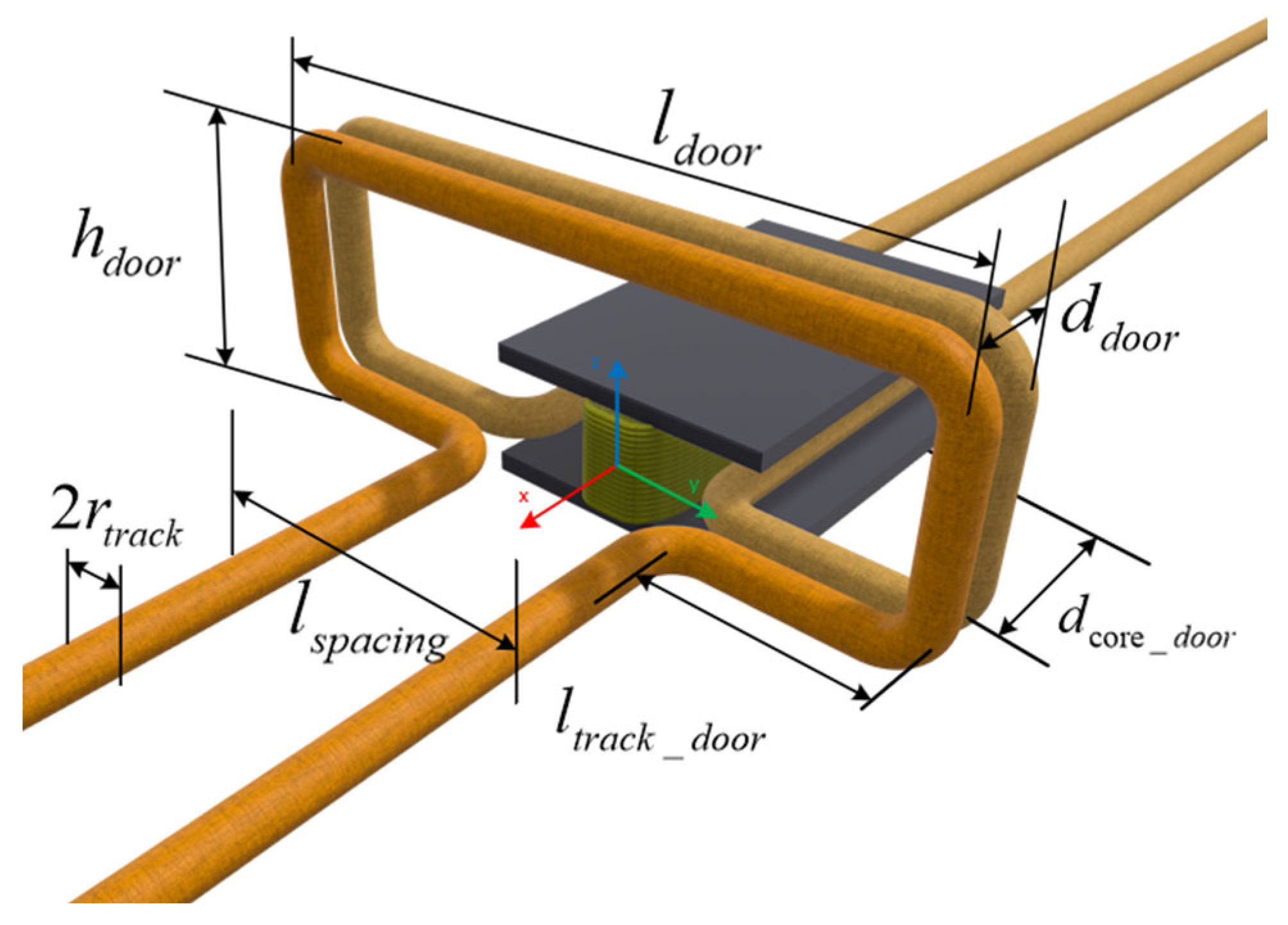
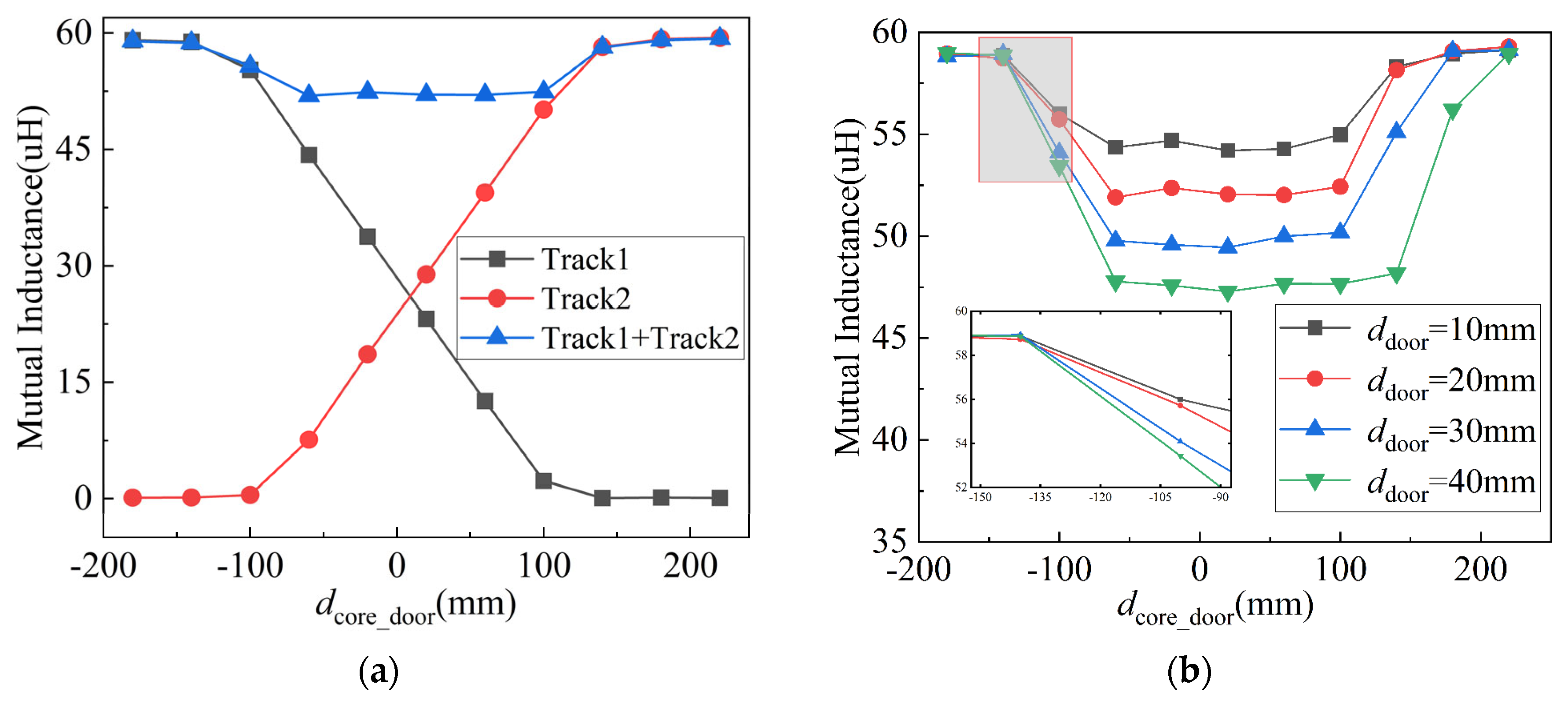
3.1. Cross-Track Operation

In the dust-free precision workshops of semiconductor wafer foundries, the complex and irregular requirements for the OHT track layout necessitate an MSWPT power pickup structure that ensures a stable power acquisition while providing operational flexibility. When the OHT moves in a straight line, it is limited by the length of the Tx track, compelling a switch to another Tx track to ensure a real-time power supply. In scenarios where the OHT operates at high speeds in a straight line, the mutual inductance is prone to attenuation during track-switching operations [22]. To ensure a seamless system operation, continuous power delivery, and the elimination of magnetic dead zones, this study adopted and examined a “door”-type track switching structure, as depicted in Figure 4. This approach enables the H-type pickup to efficiently navigate track crossovers, utilizing a door-like mechanism for this purpose.
Given the aerial transport characteristics of OHT, the Tx tracks are generally installed overhead and fixed via transport frames. Bending the tracks into a “door” shape facilitates the high-speed and smooth passage of the OHT. However, this structure introduces magnetic field nonuniformity as the H-type magnetic core Rxs power from two Tx tracks simultaneously during passage. This study analyzes various parameters of the door structure to identify factors influencing magnetic field distortion and to determine the optimal track-bending dimensions. For a clearer observation of the maximum mutual inductance attenuation, the operating speed of the pickup is set at 40 mm per step. Figure 5a illustrates the mutual inductance variation as the OHT approaches the door connection with a 20 mm track spacing, where d c o r e _ d o o r denotes the distance from the center of the magnetic core to the center of the gate structure on the X-axis, and d d o o r represents the distance between the two tracks of the door structure. It is observed that, under uniform motion conditions, there is a reduction in mutual inductance between the pickup and the track.
Reflecting on our analysis and industrial installation constraints, we chose a d d o o r = 20 mm track spacing in our gate structure, which resulted in a 11.7% reduction in mutual inductance for the dual-track power collection system.
The “door”-type track switching method, utilized for crossing tracks, encounters mutual inductance attenuation due to magnetic field distortion. Consequently, we analyze and determine the optimal dimensions for the track spacing in this door-type structure. This involves simulating the trend of mutual inductance variations at different spacings through a finite element simulation, as illustrated in Figure 5b. It is observed that the larger the track gap d d o o r at the door-type structure, the more pronounced the mutual inductance attenuation and the slower its recovery. Additionally, simulations were conducted to derive the relationship between the door-type structure’s dimensional parameters, h d o o r and l d o o r , and the mutual inductance variation curve, as illustrated in Figure 5c,d. Here, l t r a c k _ d o o r denotes the distance from the magnetic core’s center to the edge of the door-type structure along the Y-axis.
Figure 5c illustrates the relationship between the length of the outward bending of the track in the door-type structure, denoted as l t r a c k _ d o o r , and mutual inductance. Figure 5d shows the impact of the door-type structure’s height, h d o o r , on mutual inductance. Here, h d o o r represents the distance from the top edge of the magnetic core to the upper edge of the door-type structure along the Z-axis. As indicated in Figure 5c,d, while an increase in the width parameter l d o o r has an insignificant effect on mutual inductance, an increase in the height parameter h d o o r positively influences the mutual inductance parameters. A height increase of 50 mm results in a 3.66% increase in mutual inductance. Therefore, raising the height of the door-type structure can reduce the magnetic field distortion rate and is beneficial for the energy acquisition of the pickup.

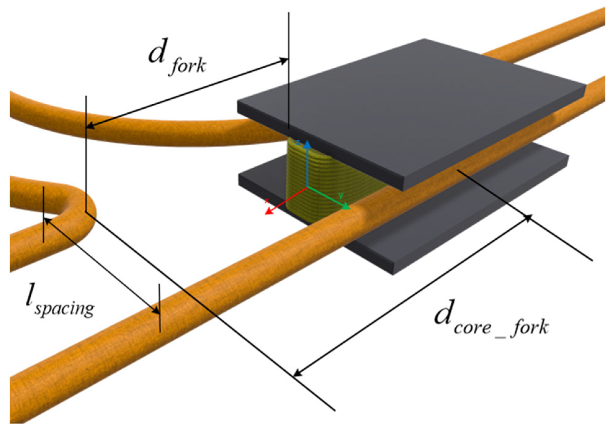
3.2. Turnout Track Running

In material handling with OHT, scenarios where a transition to single-wire energy pickup occurs are inevitable, as illustrated in Figure 6. For instances where this shift happens, we simulate the corresponding mutual inductance attenuation, as shown in Figure 7a. This simulation captures the occurrence of single-wire energy pickup resulting from an unexpected divergence in the OHT’s straight path. It is observed that when the OHT traverses a fork, the mutual inductance decreases to varying extents due to the transient single-wire energy pickup process. Specifically, the mutual inductance diminishes by 11.3% when the fork’s width and the track spacing l s p a c i n g are equivalent. In addition, the recovery of mutual sensing is slower than the fall rate under the uniform speed condition, and this phenomenon is more pronounced as the width of the turnout increases.
Since the level of mutual inductance drop determines the design of the subsequent DC/DC circuits and the selection of the supercapacitor, the parameters l s p a c i n g should be designed to ensure that the level of mutual inductance drop is within an acceptable range while considering the smooth operation of the OHT. Figure 7b shows that the mutual inductance between the pickup and the Tx track has different levels of drop when the width of the fork is different.

4. Power Loss and Design Process Analysis

4.1. Analysis of Ferrite Heat and Power Loss

During prolonged dynamic power supply operations, the losses in the magnetic coupler account for a significant portion of the system’s total losses, such as the alternating current losses in the coil and the core losses. This leads to an increase in the temperature of both the coil and the core. In scenarios of extended system operation, an uncontrolled temperature rise can pose a challenge to the system’s operational safety. A simulation of the temperature distribution for the H-type magnetic coupler was conducted, as illustrated in the accompanying Figure 8. Under natural convection conditions, the highest temperatures on the top and bottom plates of the H-type magnetic core are concentrated in the area contacting the center pillar, peaking at 37 °C. The maximum temperature differential within the core rises up to 7 °C. The center pillar of the core, being the area of maximum contact between the coil and the core, shows the primary concentration of temperature rise, as evident from the thermal field diagram. It is assumed that the thermal contact between the coil and the core is efficient. Due to the tight winding of the Rx coil around the center pillar of the H-type pickup, the multiple turns of the coil contribute to poor heat dissipation in this area, resulting in a noticeable temperature increase in the center pillar region. Therefore, in designing the magnetic core casing, ventilation should be specifically considered for the center pillar to enhance cooling. In the MSWPT system, the number of coil turns determines the magnitude of the inductive voltage in the Rx coil from (14) [23].
M μ N 2 2
u s = j w M I p
where μ is the vacuum permeability.
Considering the power level required by the Rx’s load, the current-carrying capacity of the Rx coil is also a critical factor. An excessively large wire diameter effectively increases the width of the core’s center pillar, which is not conducive to a smooth operation between tracks. Figure 7b illustrates the mutual inductance variation curves under different track spacings. The spacing between tracks is inversely related to the power transmission capacity, indirectly limiting the power transmission level of the OHT.
For systems designed based on power requirements, the dimensions of the magnetic core were determined in accordance with factors like magnetic saturation, and this was validated through finite element simulation. Given that semiconductor wafer foundries require uninterrupted operation, the conversion of all losses into heat poses a safety risk to these continuously operating facilities. The power transmission losses P l o s s can be categorized into supply track losses P c o n 1 , pickup coil conduction losses P c o n 2 , and core losses P c o r e .
P l o s s = P c o n 1 + P c o n 2 + P c o r e
P c o n 1 = I p 2 R p
P c o n 2 = I s 2 R s
The losses in a ferrite core structure encompass eddy current losses, hysteresis losses, and residual losses. During the magnetization and demagnetization process, the magnetic state varies with changes in the external magnetic field. This relationship between magnetic state and intensity is nonlinear, leading to asynchronous behavior in the hysteresis loops, which, in turn, causes residual losses. Given that these residual losses are comparatively minor at working frequencies below 500 kHz, they are disregarded in this context. In the scenario of sinusoidal induction excitation, the time-averaged power loss per unit volume can be calculated according to the Steinmetz equation [24]:
P core = K f α B m β
where K , α , and β are curve-fitting parameters from the manufacturer’s extensive experimental testing. f is the coil frequency, and B m is the peak flux density.
From (18), it can be seen that the core loss is related to the frequency and peak flux density. Therefore, the principle of core size design is based on the premise that the magnetic flux is not saturated. A combination of (4) and finite element simulation were used to analyze the core loss, as shown in Figure 9. It can be seen that the frequency and current magnitude are positive correlations that affect the core loss.
The structure on the Tx side that transfers energy to the pickup coil is a long single-turn track with a constant high-frequency current, so the coil loss P c o n 1 on the transmitter side should be determined by the track length.
η = P o u t P o u t + P loss
According to the formulas for calculating losses and efficiency, the primary losses on both the transmitter and receiver sides are predominantly concentrated in the heat generated by the coil’s AC internal resistance. In the state where the magnetic core is not saturated, the core loss accounts for a smaller proportion of the total loss. When calculating transmission efficiency by considering only wire and core losses, methods to improve efficiency include increasing the quality factor and reducing the coil current.

4.2. Analysis of Design Process

For a wireless power supply system that determines the power demand load, the overall power loss at the receiver end depends on the energy-harvesting capability of the pickup and the load rate. Since the OHT system has more than one Rx pickup structures on its MSWPT, a multi-load system is not the focus of this study, and, therefore, it is not discussed here. The energy harvesting capability is intuitively reflected by mutual inductance, as given by (21).
M = k L p L s
where k is the coupling coefficient between the Rx coil and the Tx coil. Mutual inductance is affected by the self-inductance of the Rx coil. Considering the number of turns and wire diameter of the Rx coil is crucial to ensuring inductive voltage. Additionally, excessive wire diameter and turns not only affect the heat dissipation of the central column but are also detrimental to the normal operation of OHT.
Based on the above analysis, we can establish the design flow of the Rx side for the MSWPT system used in AMHS as shown in Figure 10. Based on the factory’s track spacing and wire diameter, a preliminary shape and size parameter design with minimal tolerance was developed for the coupler. When designing the dimensions of the upper and lower plates, the variation in mutual inductance concerning their positions relative to the track should be considered. Subsequently, the selection of the Rx coil wire diameter is based on the power demand, taking into account track spacing and voltage resistance to calculate the inductive voltage required to meet power needs. Finally, the ultimate size parameters are determined through finite element simulation, assessing magnetic flux saturation levels. Once the expected level of magnetic core saturation is confirmed, the system parameters are finalized, and the design includes a dual-coil structure, compensating capacitors, and a DC/DC converter.

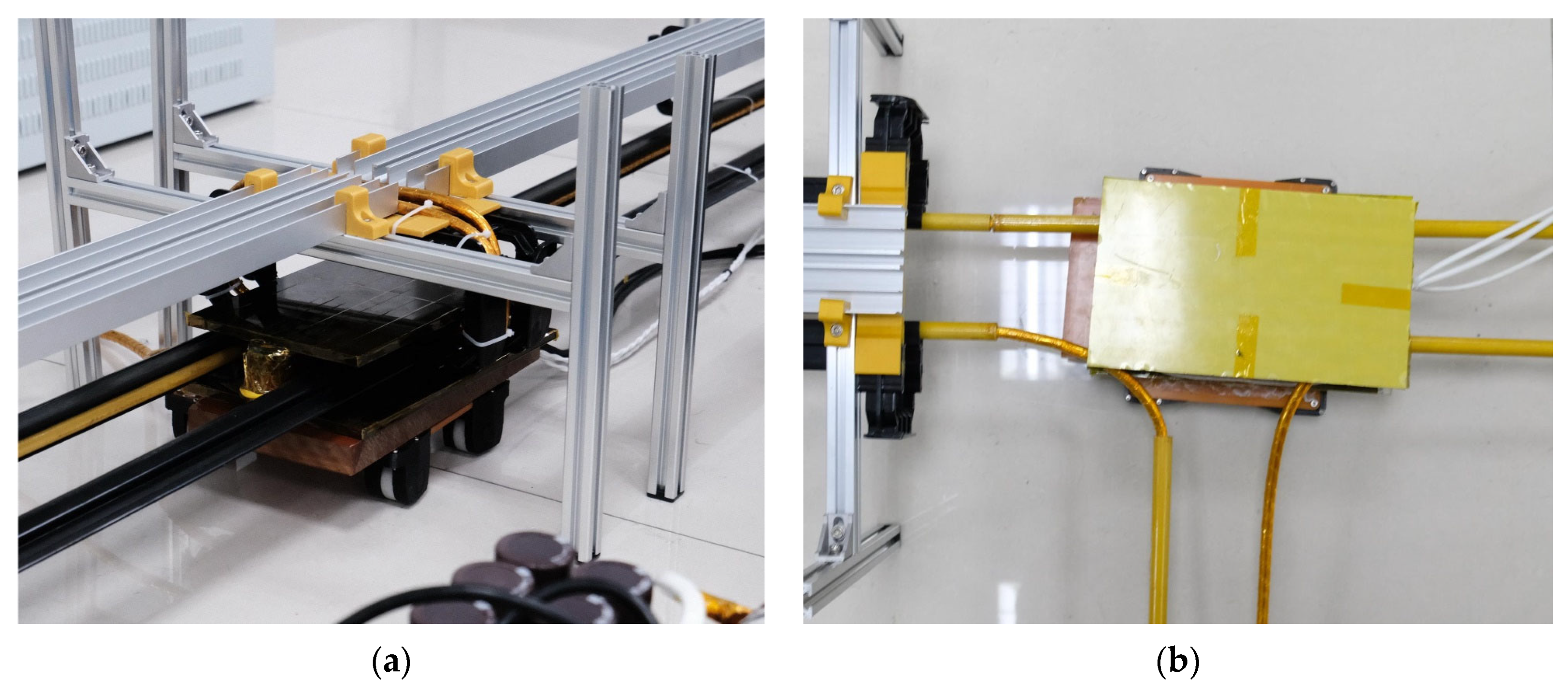
5. Experimental Verification

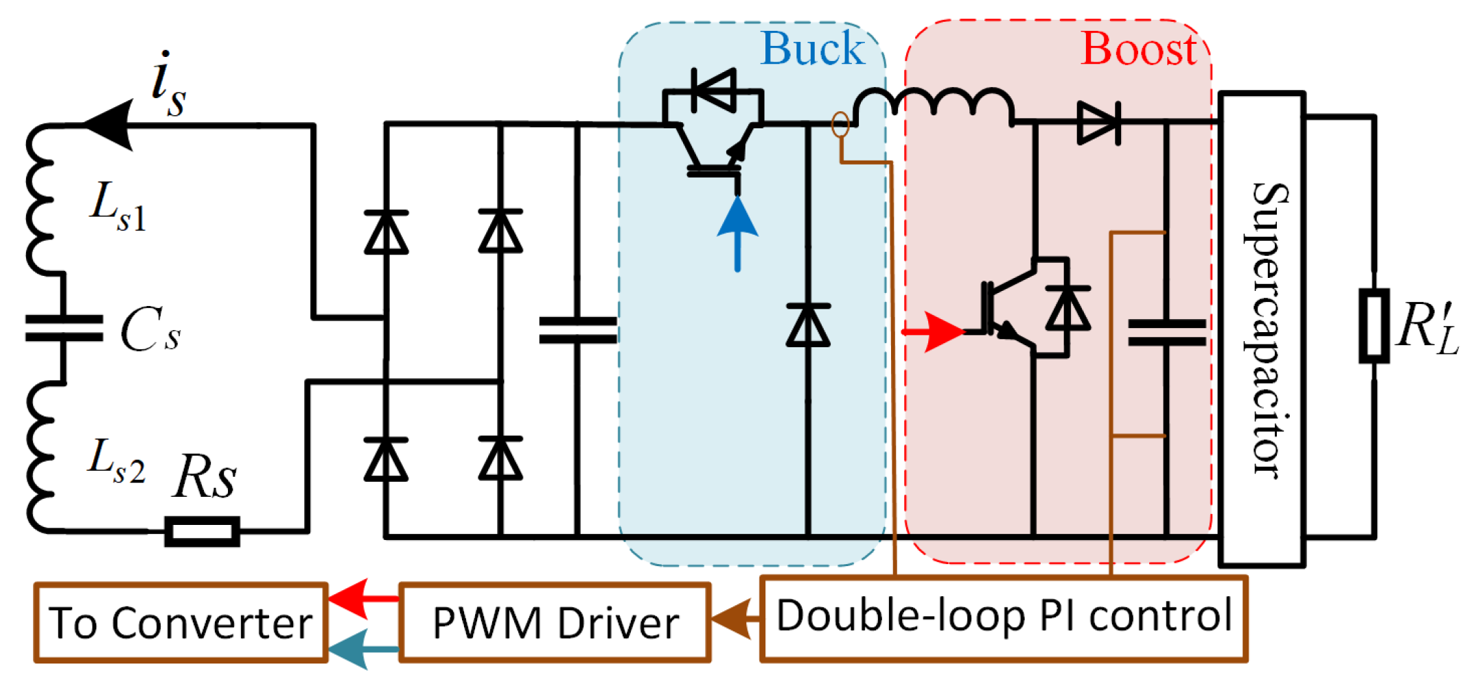
5.1. Design of H-Type Pickup and Rx Circuit

In the design of magnetic cores for industrial applications, it is essential to consider the complexity of the manufacturing process for the core shape, especially in light of procurement volume constraints. Complex magnetic core structures are often constructed using multiple assembled core units. Due to limitations in the manufacturing process, it is challenging to avoid gaps resulting from the assembly of these magnetic core units. These gaps can lead to sudden changes in magnetic reluctance, distorting the magnetic flux pathway. This distortion can result in excessive losses, localized overheating, and the premature aging of the magnetic core [25]. To provide a stable 300 V DC voltage to the load with a power of 1.5 kW, in this section, based on the constant-current characteristics of the Tx and the constant-voltage characteristics of the receiving end in the LCC-S structure, we set the track current of the Tx to a constant 80 A through a phase-shift modulation structure. Based on the simulation results from the previous section, we designed an H-type collector that can be used for optimization in the OHT system. Additionally, we concurrently developed a buck–boost structure suitable for this collector configuration, as illustrated in Figure 11.
According to the above analysis, we built two units to wirelessly power the transmitter-side structure and one unit to receive the electrical energy structure shown in Figure 12. Among them, the parameters of the Tx and receiving end are shown in Table 1. The inverter on the Tx uses the FF450R12KT4 model IGBT module from Infineon, while the receiving end employs the C2M0080120D model SiC MOSFET. Both the Tx and Rx sides use the STM32F407ZET series chip for their control systems. The primary functions on the transmitting side are phase-shift modulation for voltage regulation and soft starting, whereas the receiving side employs a dual-loop PI control. The dual-loop PI control utilizes an inner-loop inductor-current-control and an outer-loop output-voltage-control method in order to achieve the effect of stabilizing the output voltage. Considering the electromagnetic interference and equipment compatibility in semiconductor wafer factories, we selected a system resonance frequency of 9.7 kHz. The operational parameters of the Tx with a 1.5 kW load are as shown in Figure 13.
Utilizing prior finite element analysis and considering the core’s relative position to the track, we determined the magnetic core’s dimensions, as depicted in Figure 12, to meet specified inductive voltage and power requirements. Additionally, the thermal parameters of the magnetic core were simulated in ICEPAK to ensure compatibility with the system’s commercialization needs. We selected an appropriate track spacing of 65 mm to ensure that the magnetic core can switch flexibly between tracks. To facilitate testing, we designed the fork spacing to be regulated at 65 mm. With the simulation meeting the practical operational requirements, we present the pickup structure as illustrated, along with the magnetic core’s dimensional parameters and operational parameters, as shown in Figure 14 and Table 2.

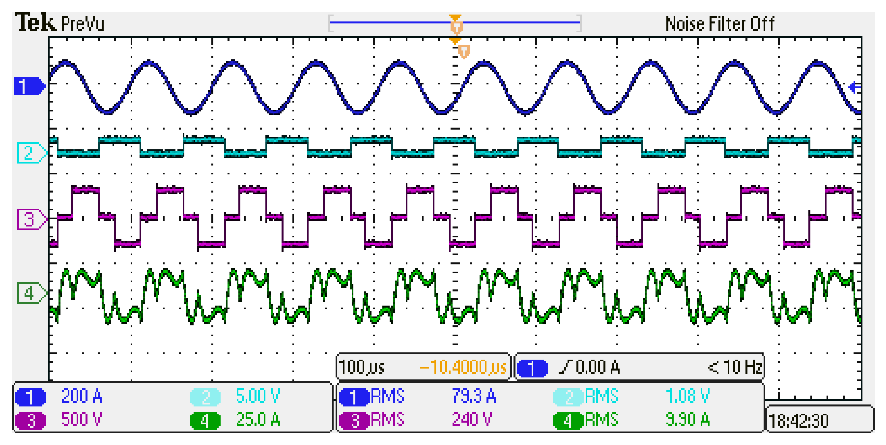
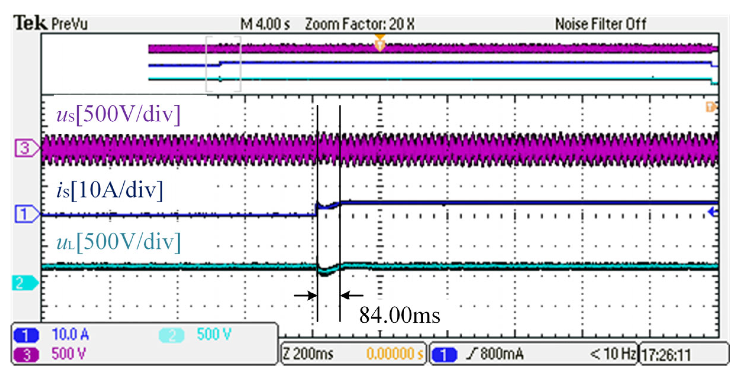
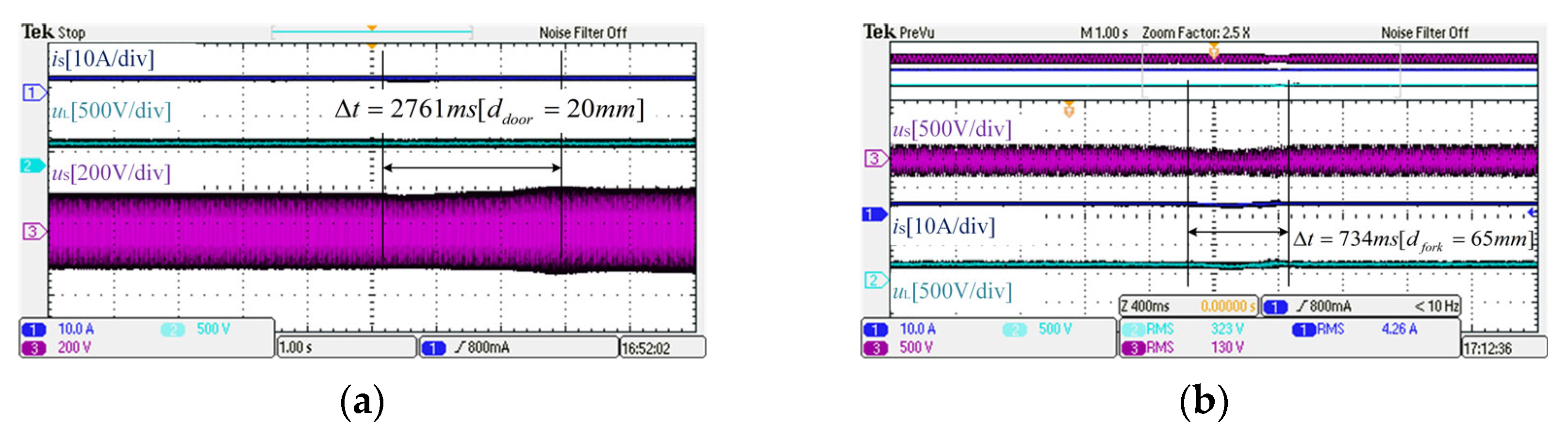
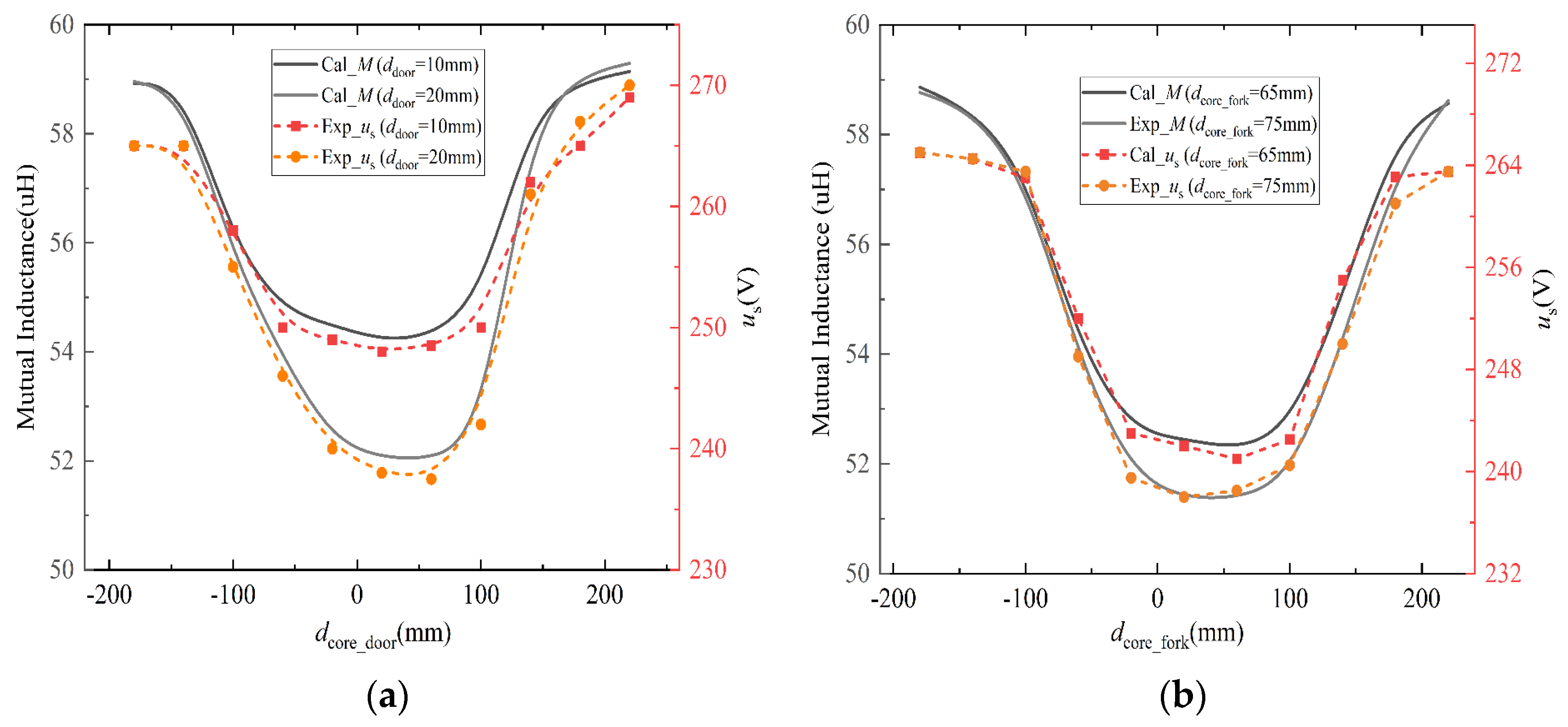
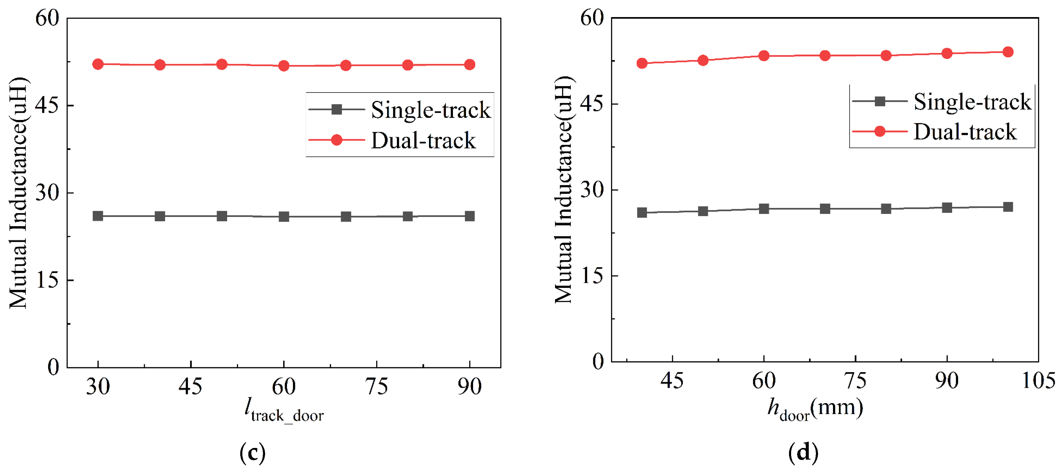
5.2. Experimental and Comparative Analyses

To verify the performance of the H-pickup designed in the previous section as well as the overall functional realization of the Rx, we first verified the stability of the described dual-loop PI control using load variation experiments. In our design, we chose the parameters p = 0.1 and i = 45 for the current inner loop and p = 0.05 and i = 50 for the voltage parameters. The transient process of the system, when the power is switched from 250 W to 1.5 kW when the output voltage is stabilized, is verified in Figure 15. As shown in Figure 15, the Rx system, equipped with double-loop control, demonstrates improved performance across various parameters. After three hours of operational testing, the core temperature slowly increased to 47 °C, thus confirming the operational performance of the designed core structure.
Based on the simulations in the previous section, we modeled the operational conditions described earlier for a gantry type crossing the track ( d d o o r = 20 mm) and operating through a junction ( d f o r k = 65 mm), as shown in Figure 16a,b, resulting in the waveforms shown in Figure 17a,b. Since we simulated the collector’s operating speed at 0.5 m/s, it is evident that under both operational conditions, there are varying degrees of drop in the load current, and voltage fluctuations self-correct under the dual-loop PI control. Therefore, when increasing speed, it is necessary to select suitable DC/DC inductor and capacitor parameters according to the speed.
To test the stability of the dual-loop PI control, we specified that the vehicle simulating the OHT operates at a speed of 0.1 m/s during the test. The internal inductance of the buck–boost was set to 2.8 mH and the capacitance to 45 μF. The output parameter states under two different operating conditions can be observed in Figure 18a,b, as illustrated in the respective diagrams. When the collector operates at a lower speed, the stability of the output parameters is not only due to the natural damping effect of the inductance and capacitance in the DC/DC segment but also attributed to the effective control of the PI system.
Due to the implementation of a dual-loop PI constant-voltage control system on the load side of this system, the load parameters do not precisely reflect the degree of mutual inductance drop. We, therefore, express the drop in mutual inductance using the inductive voltage u s as a medium. By actively adjusting the operational state of the H-type pickup, we obtain trends in the induced voltage under two different conditions as shown in Figure 19a,b, which are compared with the mutual inductance drop trends from earlier simulations. The trend of the drop-in u s effectively validates our previous research. Additionally, due to slight differences in track currents and experimental parameter matching errors, there is a minor deviation between the experimental data and the simulations. In industrial applications, supercapacitors are paralleled on the load side to address induced voltage fluctuations, a necessity given the typical 5 m/s travel speed of OHTs and the resulting variations in mutual inductance.
To validate the adaptability of the magnetic core designed in this study for track-based wireless power supply systems, we conducted comparative operational tests using three different collector structures. The control group utilized E-type, S-type, and Flat E-type magnetic cores (see Table 3), which are commonly seen and practically employed in the field of track-based wireless electrical energy transmission, as noted in [19]. According to the comparative analysis in the table, the E-type core is suitable for high-power levels but presents challenges in track switching; the S-type core exhibits superior transmission capabilities compared to other cores but has been slow to gain industrial acceptance; the Flat E-type core, in contrast to embedded cores, has relatively lower transmission capacity. Therefore, in middle-power MSWPT systems, the H-type magnetic core emerges as the unequivocal best choice.

6. Conclusions

This paper introduces an H-type pickup design optimized for dynamic MSWPT systems used in OHT applications, featuring a dual-loop PI control system for the receiver. The study begins with the development of a preliminary H-type magnetic core model, integrating circuit and magnetic circuit analyses under actual operational conditions. This approach led to the discovery of voltage stress advantages through magnetic field and thermal simulations. The paper details the formulation of a wire length calculation for the dual-coil winding method and outlines the design process for the pickup. The analysis of mutual inductance decrement trends under two specific OHT operating conditions, and the influence of various parameters on this decrement, form a significant part of the study. Finally, in this study, an MSWPT system was constructed based on LCC-S topology, verifying the constant-voltage output capability of the system at a 1.5 kW power.

Author Contributions

Conceptualization, J.W. and Z.S.; methodology, J.W.; software, Y.H.; validation, Q.S.; writing—original draft preparation, Y.G.; writing—review and editing, S.C.; project administration, Z.L.; funding acquisition, Z.L. All authors have read and agreed to the published version of the manuscript.

Funding

This research was funded by Natural Science Foundation of Shandong Province under Grant No. ZR2021ME009.

Data Availability Statement

Due to the privacy of the data, the data is not shared here.

Conflicts of Interest

The authors declare no conflict of interest.

Abbreviations

The following abbreviations are used in this manuscript:
SymbolMeaningSymbolMeaning
LspacingTx track spacingLt2Length of upper plates of magnetic core
dforkFork spacingLt1Width of the upper plates of the core
hdoorThe height of the door structureTm1Newel column width
ldoorThe width of the door structureTt1Thickness of the upper plates of the core
ddoorTrack spacing at cross-trackTd1Width of the lower plates of the core
ltrack_doorDoor structure width excluding track spacingLd1Thickness of the lower plates of the core
hmCenter column heightLd2Length of lower plates of magnetic core

References

  1. Zhou, L.; Liu, S.; Li, Y.; Mai, R.; Li, Y.; Fu, L.; Qi, L. Efficiency Optimization of LCC-S Compensated Multiple-Receiver Bidirectional WPT System for Stackers in Automated Storage and Retrieval Systems. IEEE Trans. Power Electron. 2022, 37, 15693–15705. [Google Scholar] [CrossRef]
  2. Lee, E.S.; Kim, M.Y.; Kang, S.M.; Han, S.H. Segmented IPT Coil Design for Continuous Multiple Charging of an Electrified Monorail System. IEEE Trans. Power Electron. 2022, 37, 3636–3649. [Google Scholar] [CrossRef]
  3. Wang, H.; Cheng, K.W.E.; Li, X.; Hu, J. A Special Magnetic Coupler Structure for Three-Coil Wireless Power Transfer: Analysis, Design, and Experimental Verification. IEEE Trans. Magn. 2021, 57, 8002108. [Google Scholar] [CrossRef]
  4. Tavakoli, R.; Pantic, Z. Analysis, Design, and Demonstration of a 25-kW Dynamic Wireless Charging System for Roadway Electric Vehicles. IEEE J. Emerg. Sel. Top. Power Electron. 2018, 6, 1378–1393. [Google Scholar] [CrossRef]
  5. Mahesh, A.; Chokkalingam, B.; Mihet-Popa, L. Inductive wireless power transfer charging for electric vehicles–A review. IEEE Access 2021, 9, 137667–137713. [Google Scholar] [CrossRef]
  6. Lee, S.-H.; Lee, B.-S.; Lee, J.-H. A New Design Methodology for a 300-kW, Low Flux Density, Large Air Gap, Online Wireless Power Transfer System. IEEE Trans. Ind. Appl. 2016, 52, 4234–4242. [Google Scholar] [CrossRef]
  7. Barmada, S.; Musolino, A.; Zhu, J.; Yang, S. A Novel Coil Architecture for Interoperability and Tolerance to Misalignment in Electric Vehicle WPT. IEEE Trans. Magn. 2023, 59, 8600205. [Google Scholar] [CrossRef]
  8. Song, B.; Cui, S.; Li, Y.; Zhu, C. A Fast and General Method to Calculate Mutual Inductance for EV Dynamic Wireless Charging System. IEEE Trans. Power Electron. 2021, 36, 2696–2709. [Google Scholar] [CrossRef]
  9. Beh, H.Z.; Neath, M.; Boys, J.T.; Covic, G.A. An Alternative IPT Pickup Controller for Material Handling Using a Current Doubler. IEEE Trans. Power Electron. 2018, 33, 10135–10147. [Google Scholar] [CrossRef]
  10. Pearce, M.G.S.; Covic, G.A.; Boys, J.T. Reduced Ferrite Double D Pad for Roadway IPT Applications. IEEE Trans. Power Electron. 2021, 36, 5055–5068. [Google Scholar] [CrossRef]
  11. Chakibanda, V.; Komanapalli, V.L.N. Optimization in Magnetic Coupler Design for Inductively Coupled Wireless Charging of Electric Vehicle: A Review. Arab. J. Sci. Eng. 2023, 48, 14257–14294. [Google Scholar] [CrossRef]
  12. Zeng, H.; Liu, Z.; Hou, Y.; Hei, T.; Zhou, B. Optimization of Magnetic Core Structure for Wireless Charging Coupler. IEEE Trans. Magn. 2017, 53, 8000804. [Google Scholar] [CrossRef]
  13. Kim, D.; Lee, S. Propulsion and Control of Microrobot Using a Multi-Selective Wireless Power Transfer Coil. IEEE Trans. Magn. 2023, 59, 8000806. [Google Scholar] [CrossRef]
  14. Han, W.; Chau, K.T.; Jiang, C.; Liu, W.; Lam, W.H. Design and Analysis of Quasi-Omnidirectional Dynamic Wireless Power Transfer for Fly-and-Charge. IEEE Trans. Magn. 2019, 55, 8001709. [Google Scholar] [CrossRef]
  15. Shin, J.; Shin, S.; Kim, Y.; Ahn, S.; Lee, S.; Jung, G.; Jeon, S.-J.; Cho, D.-H. Design and Implementation of Shaped Magnetic-Resonance-Based Wireless Power Transfer System for Roadway-Powered Moving Electric Vehicles. IEEE Trans. Ind. Electron. 2014, 61, 1179–1192. [Google Scholar] [CrossRef]
  16. Choi, S.Y.; Jeong, S.Y.; Gu, B.W.; Lim, G.C.; Ultraslim, C.T.R. S-Type Power Supply Rails for Roadway-Powered Electric Vehicles. IEEE Trans. Power Electron. 2015, 30, 6456–6468. [Google Scholar] [CrossRef]
  17. Huh, J.; Lee, S.W.; Lee, W.Y.; Cho, G.H.; Rim, C.T. Narrow-Width Inductive Power Transfer System for Online Electrical Vehicles. IEEE Trans. Power Electron. 2011, 26, 3666–3679. [Google Scholar] [CrossRef]
  18. Zhang, Q.; Song, S.; Dong, S.; Zhu, C. Receiver-Side-Oriented Simulator for Dynamic Wireless Charging System with I-Type Transmitter and Multiphase Receiver. IEEE Trans. Ind. Electron. 2021, 68, 3906–3916. [Google Scholar] [CrossRef]
  19. Boys, J.T.; Covic, G.A. The Inductive Power Transfer Story at the University of Auckland. IEEE Circuits Syst. Mag. 2015, 15, 6–27. [Google Scholar] [CrossRef]
  20. Hwang, I.; Jang, Y.J.; Choi, H. Overhead shuttle design for a flat panel display production line considering the contactless power supply capacity. Comput. Ind. Eng. 2018, 126, 232–242. [Google Scholar] [CrossRef]
  21. Hong, S.; Hwang, I.; Jang, Y.J. Practical Q-Learning-Based Route-Guidance and Vehicle Assignment for OHT Systems in Semiconductor Fabs. IEEE Trans. Semicond. Manuf. 2022, 35, 385–396. [Google Scholar] [CrossRef]
  22. Wang, J.; Sun, W.; Cai, S.; Guo, Y.; Liu, Z. Cross-Rail Voltage Stabilization Control Strategy for Multi-Transmitter Contactless Power System. In Proceedings of the 2023 International Conference on Power System Technology (PowerCon), Jinan, China, 21–22 September 2023; pp. 1–6. [Google Scholar]
  23. Chen, Y.; Chen, K.; Zheng, S.; Yuan, L.; Zhao, Z. Analytical Modeling Method for Inductance of Planar Magnetic Coupler in Wireless Power Transfer. Proc. Chin. Soc. Electr. Eng. 2023, 43, 1504–1517. [Google Scholar]
  24. Zhang, X.; Hao, C.; Dou, R.; Liu, S.; Zhao, L.; Zhang, P.; Yang, Q. Ferrite Pads Gap Thermal-Magnetic Evaluation and Mitigation for 11.1 kW Wireless Power Transfer. IEEE Trans. Magn. 2023, 59, 8600806. [Google Scholar] [CrossRef]
  25. Li, Z.; Han, W.; Xin, Z.; Liu, Q.; Chen, J.; Loh, P.C. A Review of Magnetic Core Materials, Core Loss Modeling and Measurements in High-Power High-Frequency Transformers. CPSS Trans. Power Electron. Appl. 2022, 7, 359–373. [Google Scholar] [CrossRef]
Figure 1. MSWPT system architecture for OHT systems in AMHS.
Electronics 13 01125 g001
Figure 2. H-type pickup magnetic field analysis. (a) Magnetic flux density distribution in H-type magnetic core. (b) Magnetic field lines of the H-type magnetic core. (c) Magnetic circuit path in an H-type magnetic core.
Electronics 13 01125 g002
Figure 3. Dual-coil winding structure of the Rx.
Electronics 13 01125 g003
Figure 4. Door-type track switching operating conditions.
Electronics 13 01125 g004
Figure 5. Variation of each parameter of door−type switching track operation: (a) mutual inductance at track switching, (b) mutual inductance at track spacing change, (c,d) mutual inductance under changes in the door type architecture parameter.
Electronics 13 01125 g005aElectronics 13 01125 g005b
Figure 6. Cross − fork operation conditions.
Electronics 13 01125 g006
Figure 7. Mutual sensing fluctuations past the operating conditions of the turnout. (a) Change in fork width; (b) single track spacing.
Electronics 13 01125 g007
Figure 8. Magnetic core temperature field distribution.
Electronics 13 01125 g008
Figure 9. Magnetic core eddy current loss distribution.
Electronics 13 01125 g009
Figure 10. Rx-side design flow.
Electronics 13 01125 g010
Figure 11. Rx buck–boost control structure.
Electronics 13 01125 g011
Figure 12. MSWPT experimental platform.
Electronics 13 01125 g012
Figure 13. Tx state when loaded with 1.5 kW.
Electronics 13 01125 g013
Figure 14. Schematic representation of the parameters of the pickup.
Electronics 13 01125 g014
Figure 15. Transient process when the load power is switched from 250 W to 1.5 kW.
Electronics 13 01125 g015
Figure 16. Two simulated operating conditions. (a) Simulating turnout track running; (b) simulation of switching operation of door track.
Electronics 13 01125 g016
Figure 17. Fluctuation of each parameter in two operating conditions at 0.5 m/s speed. (a) Door-type switching track operation; (b) turnout track running.
Electronics 13 01125 g017
Figure 18. Fluctuation of each parameter in two operating conditions at 0.1 m/s speed. (a) Door-type switching track operation; (b) turnout track running.
Electronics 13 01125 g018
Figure 19. Experimental and simulation comparison of pickup capacity under two operating conditions. (a) Door switching track; (b) turnout track running.
Electronics 13 01125 g019
Table 1. MSWPT Tx and Rx parameters.
ParametersValueParametersValue
f9.7 kHzRp0.022 Ω
Uin240 VLs11243.2 μH
Lf45.6 μHLs21182.1 μH
Cf5.9 μFCs0.0565 μF
Lp65.6 μHRs0.76 Ω
Cp13.56 μFRL60 Ω
Table 2. Magnetic selection of core parameters.
ParametersValueParametersValue
Lspacing65 mmLt2220 mm
dfork65 mmLt1150 mm
hdoor30 mmTm115 mm
ldoor221 mmTt110 mm
ddoor20 mmTd110 mm
ltrack_door78 mmLd1160 mm
hm40 mmLd2220 mm
Table 3. Comparison of different types.
H-TypeS-TypeE-TypeFlat E-Type
Transfer capabilityRelatively highHighRelatively highModerate
Operational flexibilityHighLowLowHigh
Power levelModerateModerateHighHigh
Commercialization capacityHighLowHighHigh
Disclaimer/Publisher’s Note: The statements, opinions and data contained in all publications are solely those of the individual author(s) and contributor(s) and not of MDPI and/or the editor(s). MDPI and/or the editor(s) disclaim responsibility for any injury to people or property resulting from any ideas, methods, instructions or products referred to in the content.

