Abstract
In this paper, we propose the design and simulation of a dielectric horn antenna using the metamaterial method; this antenna has a double-layer dielectric waveguide transmission structure. With the continuous development of microwave feed sources, the traditional waveguide systems are no longer able to meet today’s antenna requirements. Consequently, dielectric-loading technology is gradually being applied to design horns. A key advantage of this antenna is its significantly expanded bandwidth of 163.3%. Furthermore, when compared to ridge horns, this dielectric-loaded horn demonstrates superior radiation properties across the entire frequency band, including aperture efficiency (95% in the L band, 65.4% in the S band, 41.5% in the C band, and 28.7% in the X band) and cross-polarization isolation (≥51.6 dB). In addition, before researching the theory of dielectric-loading technology, the modes of the horns should be analyzed. This helps us to better control the hybrid mode. The metamaterial method was applied to achieve stable dielectric properties. We finally conducted experiments on the antenna to validate the relevant theories and feasibility.
1. Introduction
With the development of satellite communication and deep space exploration, ultra-band antennas have been a trend in recent years. How to achieve ultra-band horns with optimum performance has become a problem for antenna designers. In previous research, TAS-F (Thales Alenia Space France) proposed broadband corrugated horns to simultaneously cover multiple frequency bands, which involves connecting the OMJ (Ortho Mode Junction) with six ports behind the corrugated speakers to separate different frequency bands, including Ku band reception (10.7–12.75 GHz) and transmission (13.75–14.5 GHz). On this basis, wider bandwidth requirements were proposed. Thus, ridge horns are researched more regularly. For example, J R. Pyle [1] has researched them. However, because they are constrained by their structure, they are unable to achieve a high gain and high cross-polarization isolation, and directional pattern splitting may occur at high frequencies [2,3,4,5,6,7,8]. In order to achieve optimum performance in terms of gain, aperture efficiency, and cross-polarization isolation, corrugated horns have been proposed [9,10,11,12,13,14], but the bandwidth of these corrugated horns is narrow. To achieve a wider bandwidth, multi-band horns have been proposed. The multi-band horns broaden the bandwidth and perform well in aperture efficiency and cross-polarization isolation [15,16]. Nevertheless, the multi-band horns work at several different frequencies, respectively; the bandwidth for each working band is not wide.
To achieve an optimum performance for wide bands, dielectric-loaded horns were proposed. In the 1980s, a series of papers on dielectric-loaded horns were published, introducing dielectric-loading technology [17,18,19,20,21,22,23,24,25,26]. After using dielectric-loading technology, the bandwidth greatly expanded. In addition, dielectric-loaded horns have not only great aperture efficiency, but also a good cross-polarization isolation performance, because the horn mode is similar to the HE11 mode.
With developments in materials science and metamaterials, an increasing number of dielectric materials with stable dielectric constants and minimal losses have been proposed. As a result, dielectric-loaded horn antennas are undergoing rapid development. The principle behind utilizing dielectric-loaded horn antennas to achieve a wide bandwidth is to control the modes through dielectric loading. Specifically, when electromagnetic waves pass through the dielectric material, dispersion can generate effects comparable to those in optical fibers. These effects can influence the propagation speed, phase, and amplitude of electromagnetic waves, allowing various frequencies to work in different regions. Consequently, this expands the antenna’s bandwidth. During the selection of suitable dielectric materials and designs, adjustments can be made to the ranges of dielectric constant and magnetic permeability. This enables the antenna to obtain excellent impedance matching and radiation characteristics across a broad band. Furthermore, dielectric loading can modify the antenna’s gain and directionality, thereby expanding its application range.
In the process of achieving a wide band, it is necessary to comprehensively consider the physical properties and geometric parameters of the dielectric material, including the dielectric constant, the loss tangent, the thickness, the shape, and more. These parameters have an influence on the antenna’s performance, necessitating meticulous optimization and validation efforts to obtain optimum results. Overall, the key to achieving a wide band using dielectric-loaded horn antennas is selecting appropriate dielectric materials and design parameters, as well as optimizing their electrical performance. The application of this technology helps to improve the capacity and data transmission rate of communication systems, thereby fulfilling the demands of diverse scenarios.
Prior to the design of dielectric-loaded horn antennas, it is necessary to theoretically analyze the generation and excitation of hybrid modes in double-layer dielectric-loaded horns and explore the influence of dielectric topology on the distribution of hybrid-mode aperture fields. This theoretical analysis provides guidance for those using dielectric-loaded horn antenna technology. Currently, most dielectric-loading techniques are limited to numerical electromagnetic calculation methods, such as the moment and finite element methods. While these methods can be used to analyze the transmission modes of multi-layer dielectric waveguide systems, we lack a profound understanding of these modes, and these approaches are inefficient. When exploring multi-layer dielectric-loading technology, it is necessary to accurately identify all the modes of multi-layer dielectric waveguides to ensure the comprehensive analysis of the performance of a dielectric-loaded feed source antenna. Therefore, before the design of a dielectric-loaded horn antenna can be achieved, theoretical analysis of the generation and excitation of hybrid modes in double-layer dielectric-loaded horns is required. We researched the influence of dielectric topology on the distribution of hybrid mode aperture fields and provide theoretical guidance for those using dielectric-loaded horn antenna technology [27,28,29].
2. Analysis of Field in Double-Layer Dielectric-Loaded Antenna
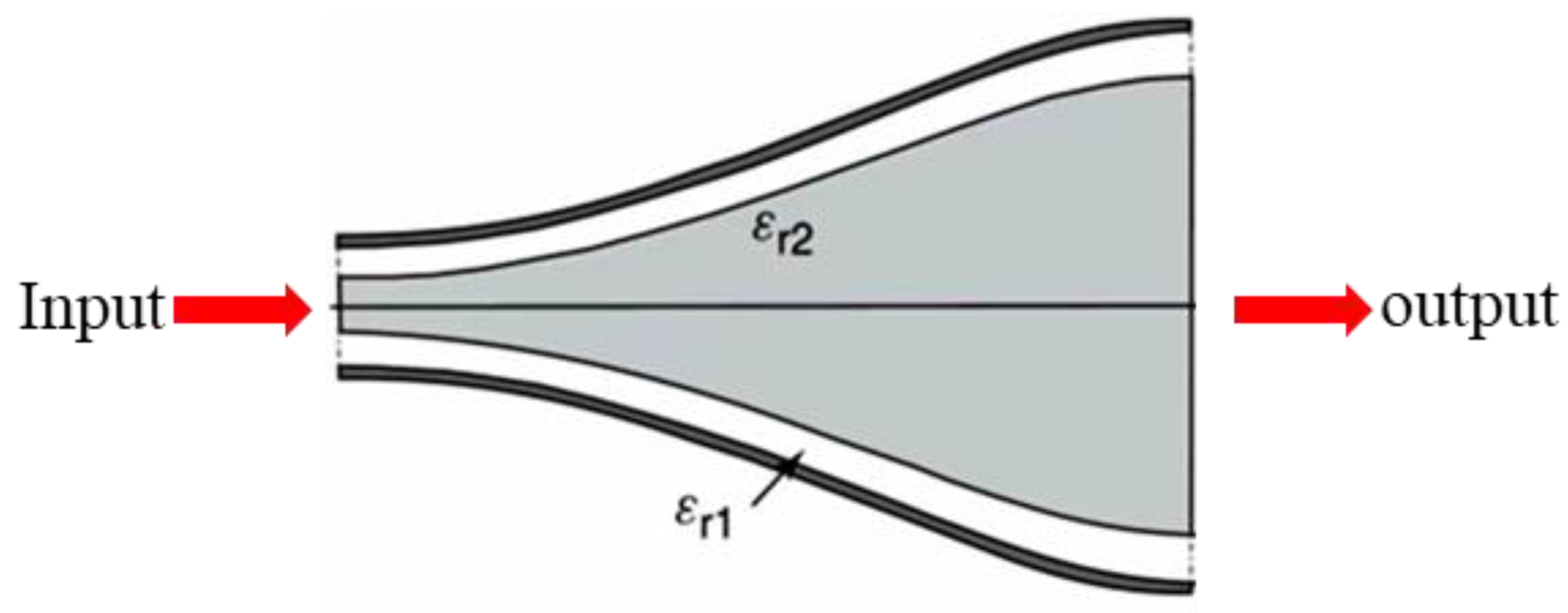
A typical double-layer dielectric-loaded horn model is shown in Figure 1.
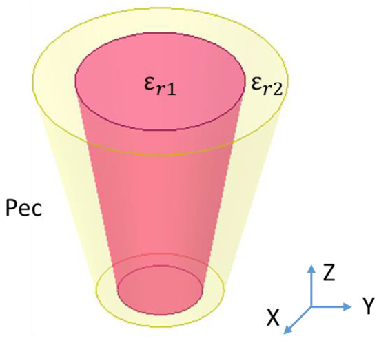
Figure 1.
Schematic of double-layer dielectric-loaded horn.
The inner layer is Zone I, which has the dielectric constant of εr1, and the outer layer is Zone II, which has the dielectric constant of εr2. The outermost layer is PEC.
Thus, the field solution for Zone I is calculated as follows:
Meanwhile, the field solution for Zone II can be expressed as follows:
In the expression shown above, I and K represent the first and second types of Bessel function of the imaginary argument, respectively. Here, .
The characteristic equation of a double-layer dielectric-loaded horn can be derived by analyzing the field distribution in each region. This characteristic equation is very complex. To express it concisely, we use the following expression:
After complex simplification, the characteristic equation of the double-layer dielectric-loaded horn structure is described as follows:
Herein, these key parameters are expressed as follows:
This expression represents the characteristic root equation of a double-layer dielectric-loaded horn. Utilizing this expression, the characteristic root and the mode field solution can be solved in the guided wave system. When m ≠ 0, the propagating modes are hybrid modes, which are HEmn and EHmn. When m = 0, the TE0n and TM0n modes are propagated. That is to say that guided wave systems such as double-layer dielectric-loaded horns can propagate the TE0n, TM0n, HEmn, and EHmn modes.
2.1. Mathematical Model of Hybrid Mode in Double-Layer Dielectric-Loaded Horn
Based on the characteristic root equation shown above, in order to obtain a clear understanding, MATLAB 2022 was used to calculate the hybrid mode aperture field distribution. After setting Freq = 2 GHz, a = 100 mm, b = 150 mm, εr1 = 3.4, and εr2 = 2.1, the field distribution of six hybrid modes in this situation can be transmitted. When m = 1, the modes are HE11, HE12, HE13, and HE14. The hybrid mode determines the HE and EH modes based on the ratio of TE11 and TM11 modes.
The hybrid mode we need is the HE11 mode, and the distribution of the main polarization and cross-polarization aperture fields of the double-layer dielectric-loaded horn main mode is shown in Figure 2 (Freq = 2 GHz; a = 100 mm; b = 150 mm; εr1 = 3.4, 2.1 = 2.1). The main polarization field is almost 40 times larger than that of cross-polarization, and the distribution of the main polarization aperture field is approximately circular, which is equalized in each section.
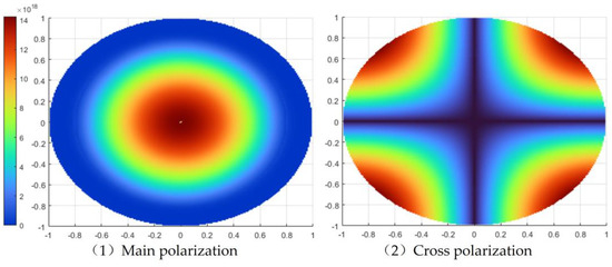
Figure 2.
Schematic representation of the aperture field distribution for the hybrid mode.
Field distribution shows that the mode of the horn is similar to that of the optimum balanced HE11 mode, which means the aperture efficiency and cross-polarization isolation performances should be good. Figure 3 is a schematic representation of the distribution of the main polarization and cross-polarization aperture fields in the hybrid mode HE11 of a double-layer dielectric waveguide.
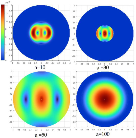
Figure 3.
Field distribution of inner dielectric size. a = 10, 30, 50, and 100 mm.
2.2. Control of Hybrid Mode HE11 in Double-Layer Dielectric-Loaded Horn
In order to control the hybrid mode, which is the HE11 mode, it is necessary to change the topology of the multi-layer dielectric horn. After that, the aperture field distribution of the HE11 mode changes. At this time, the mixing ratio remains unchanged, so it remains in the HE11 mode. The well-known HE11 mode is balanced and mixed, where the field distribution is circular at the center of the waveguide. For the other possible modes, less research has been conducted. Here, we discuss the effects of the size and dielectric constant of different dielectric materials on aperture field distribution.
We set Freq = 2 GHz, a = 100 mm, b = 150 mm, εr1 = 3.4, and εr2 = 2.1, and then changed the inner dielectric radius a and kept the other parameters constant. When a = 10 mm, 30 mm, 50 mm, and 100 mm, the size of the inner-layer dielectric material increases, and the electric field distribution is concentrated on both inner and outer sides of the outer layer (Figure 3). As the radius of the inner-layer dielectric material increases, the electric field on the outer side of the outer layer gradually disappears and transfers to the outer side of the inner layer and the inner side of the outer layer, forming a surface wave between the dielectric materials. As the radius of the inner layer continues to increase, the energy of the electric field in the middle dielectric layer gradually increases, and it finally reaches a balanced mixing mode.
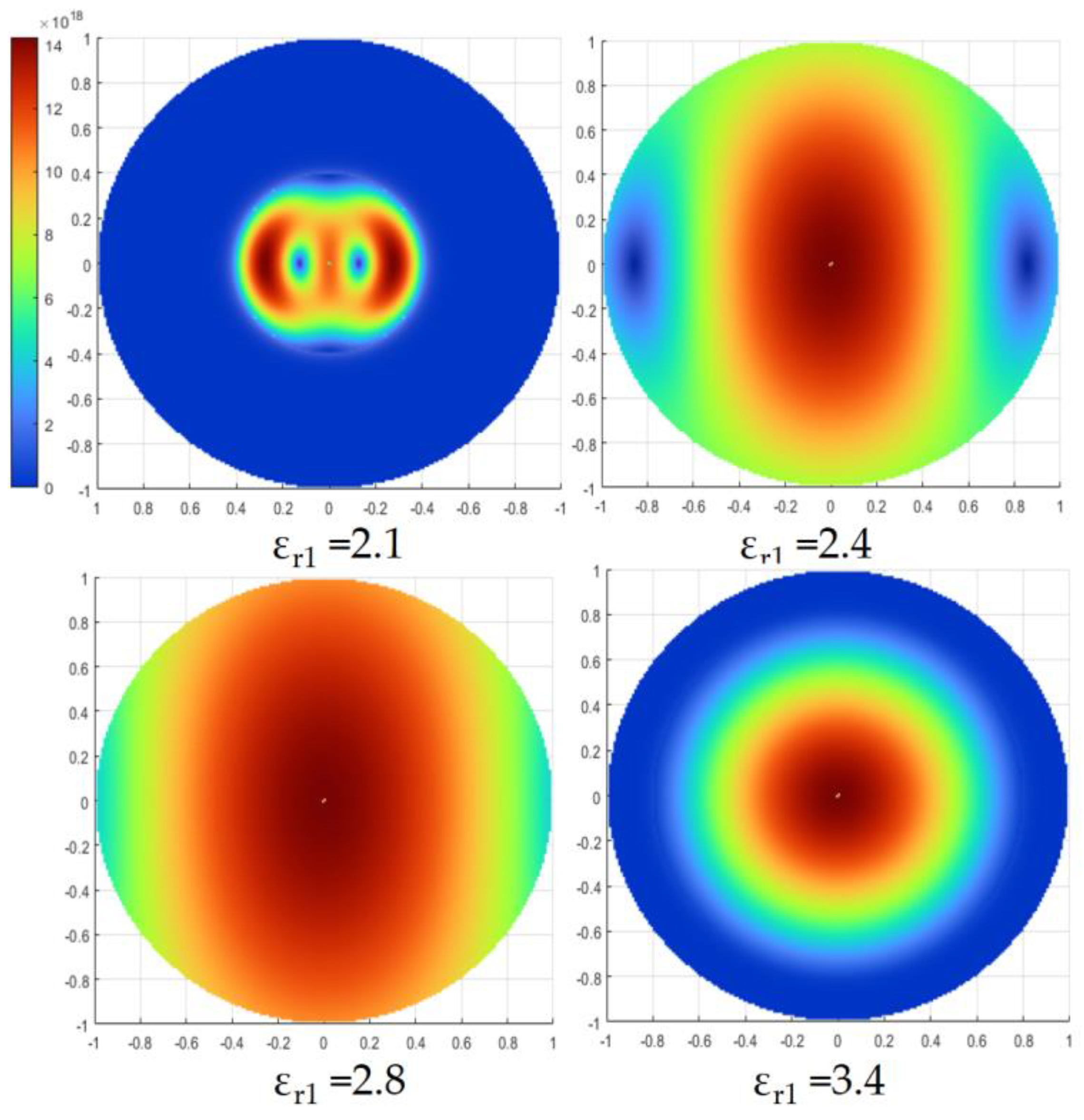
Secondly, we continue to focus on the double-layer dielectric waveguide by changing the dielectric constant εr1 of the inner layer dielectric material from 2.1 to 2.4, 2.8, and 3.4, respectively (Freq = 2 GHz, a = 100 mm, b = 150 mm, and εr2 = 2.1). From Figure 4, it can be observed that, when the dielectric constant of the inner-layer dielectric material is consistent with that of the outer layer, the main polarization field develops a circular waveguide field distribution. As the dielectric constant of the inner-layer dielectric material gradually increases, the main polarization electric field distribution gradually becomes circular; finally, the balanced mixing mode is reached; at this point, the field distribution of each section of the aperture field is equalized.

Figure 4.
Field distribution of inner dielectric constant εr1 = 2.1, 2.4, 2.8, and 3.4.
The results above indicate that changing the topology of multi-layer dielectric waveguides can change the aperture field distribution of dielectric waveguides. Therefore, when designing multi-layer dielectric-loaded horn antennas, selecting a reasonable topology for the multi-layer dielectric waveguides can generate balanced, mixed-state HE11 modes, which can produce ideal directional patterns with a high aperture efficiency and strong cross-polarization isolation.
3. Simulation of Dielectric-Loaded Horn Antenna
With the continuous developments in materials science, more and more dielectric materials with stable dielectric constants and low losses have been proposed. Thus, dielectric-loaded horns can achieve multi-mode operation at different frequency bands through dielectric loading.
The schematic of the structure of a typical double-layer dielectric-loaded horn is shown in Figure 5. It is filled with dielectric constant materials εr1 and εr2 in the internal cavity of the horn. Based on the pattern analysis above, it can be concluded that, in order to control the dielectric-loaded horn operating in the HE11 mode, εr2 needs to be greater than εr1. Here, we select a dielectric material with an εr2 of 1.2 and an εr1 of 1 for simulation.
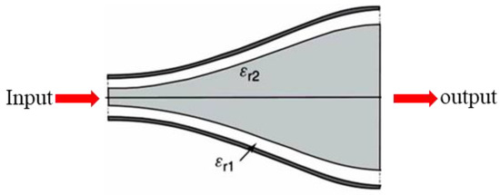
Figure 5.
A typical double-layer dielectric-loaded horn model.
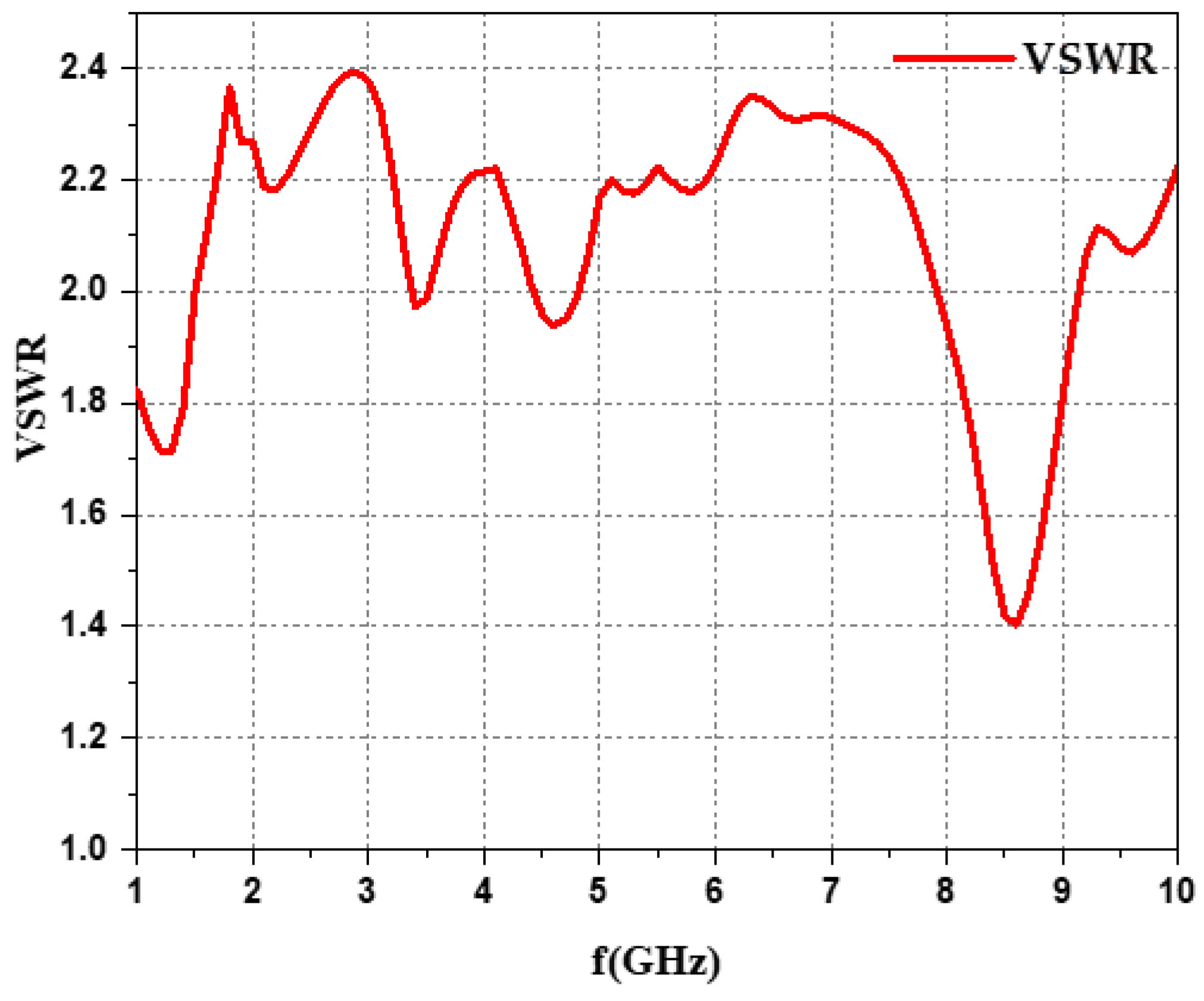
After the design of the dielectric-loaded horn antenna has been completed, the S parameter should be considered first. Here, we show the VSWR (voltage standing wave ratio) for each band (Figure 6).
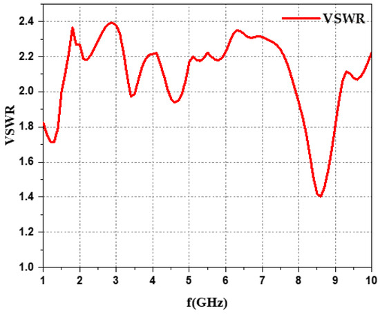
Figure 6.
VSWR.
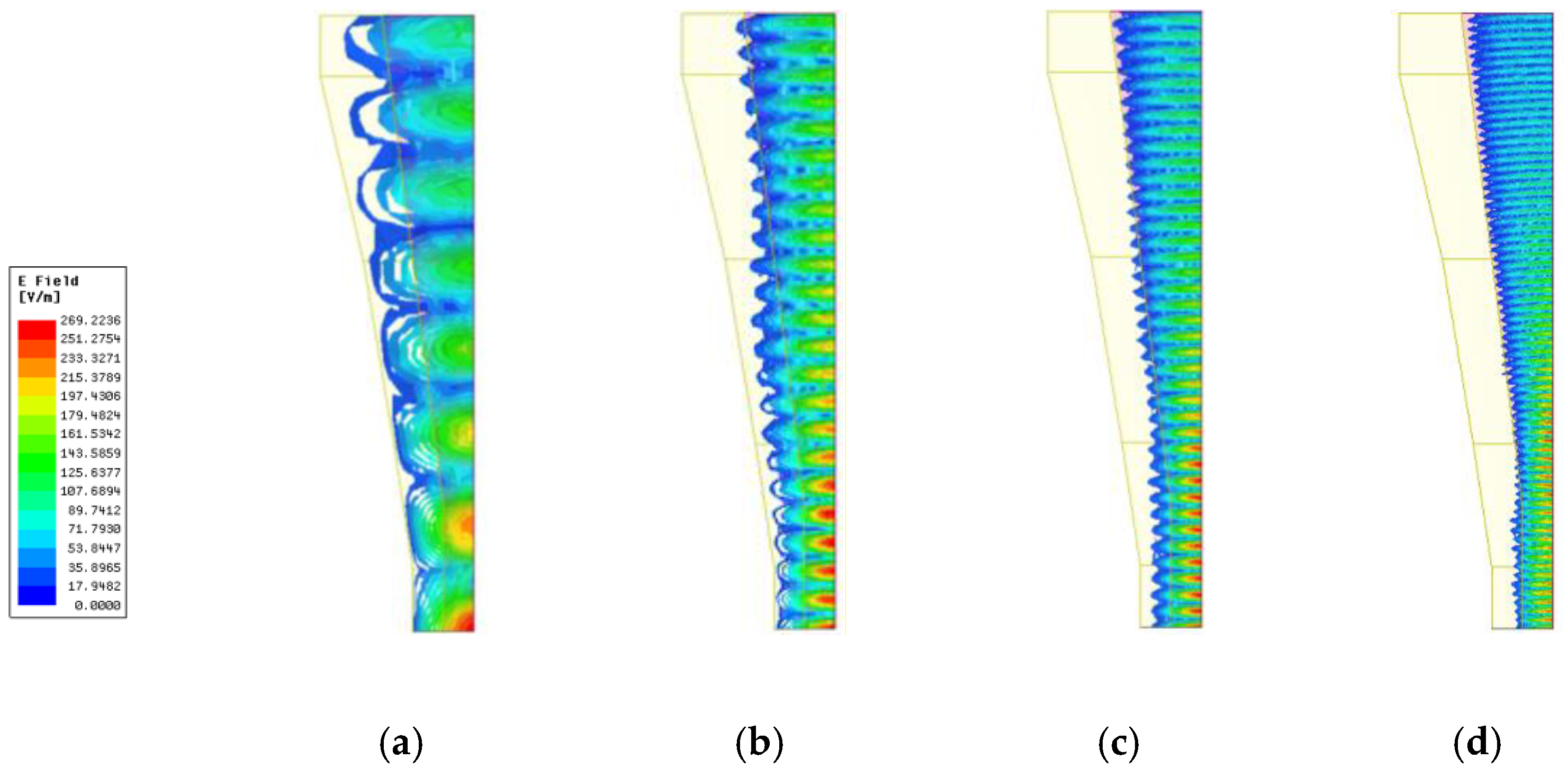
Considering the bandwidth, we apply a ridge waveguide to excite the horn. The VSWR is under 2.5 in all the bands. Around the X band, the VSWR is lower, which is under 2. Due to the influence of the loading dielectric material, when the antenna operates at low frequencies, the dielectric material has a relatively small impact on the field distribution, and the difference is not significant compared to when there is no dielectric. Electromagnetic waves propagate throughout the entire cavity. When the working frequency band is in the intermediate-frequency range, electromagnetic waves gradually return to the surface of the dielectric material, forming some surface waves. When the working frequency band is in the high-frequency range, the electromagnetic field converges towards the surface of the dielectric column, forming a surface wave working state, as shown in Figure 7.

Figure 7.
Working zone for each band. (a) L band. (b) S band. (c) C band. (d) X band.
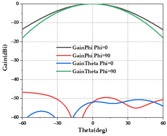
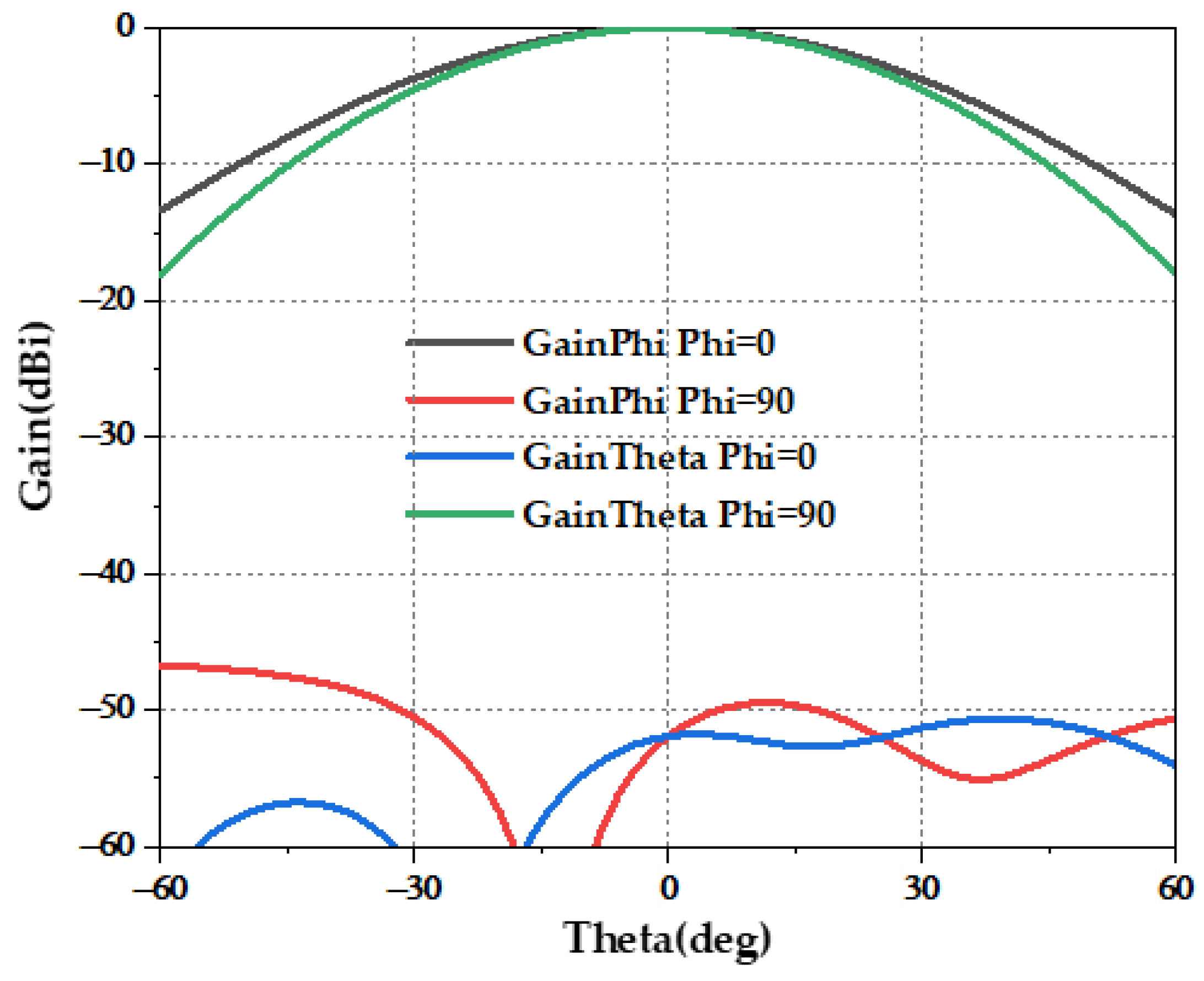
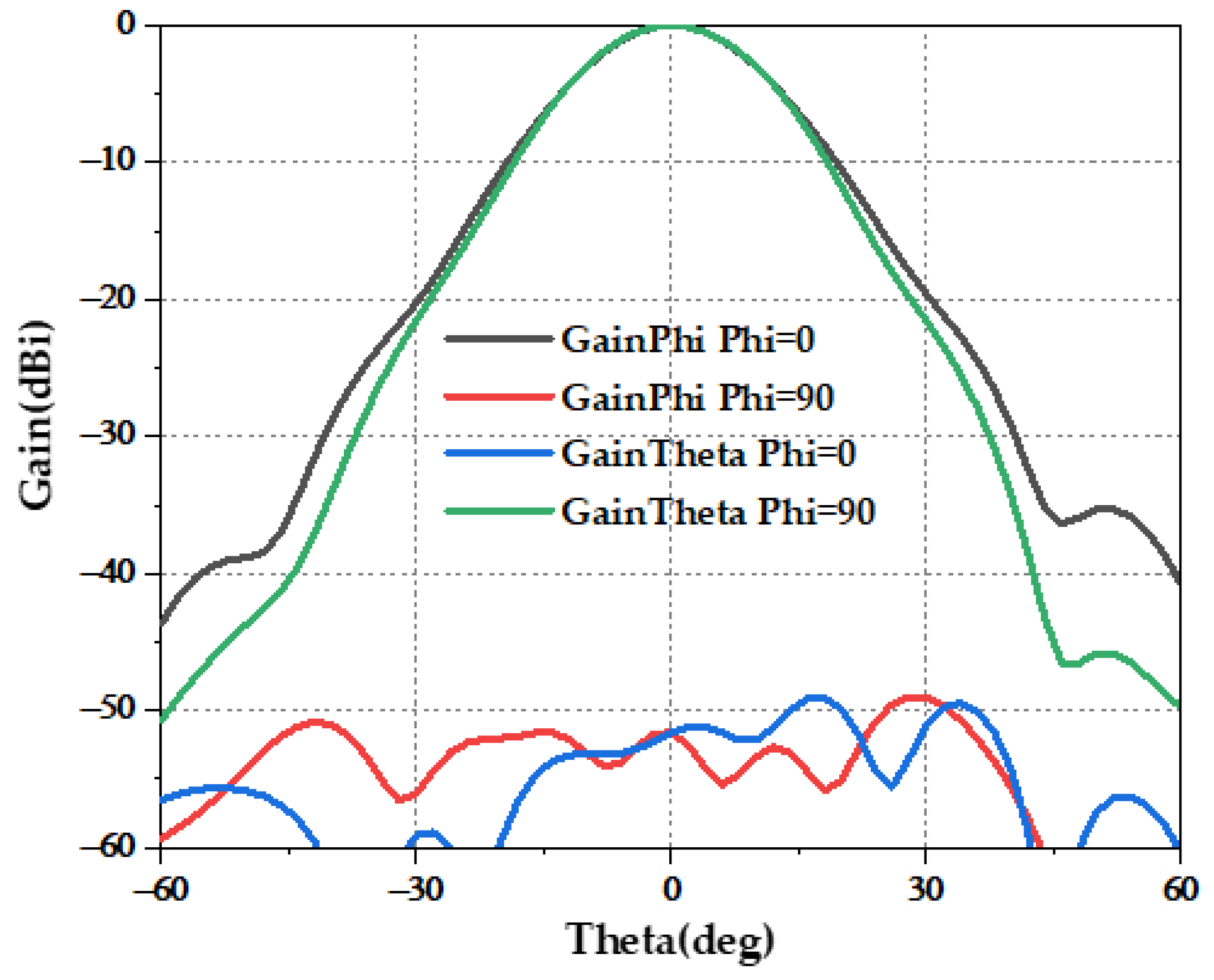
Figure 8.
L band radiation pattern.
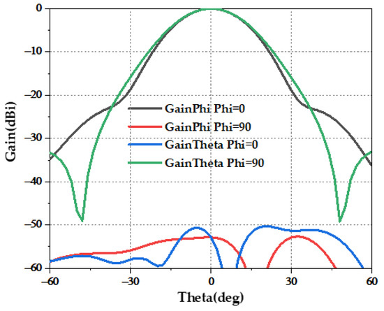
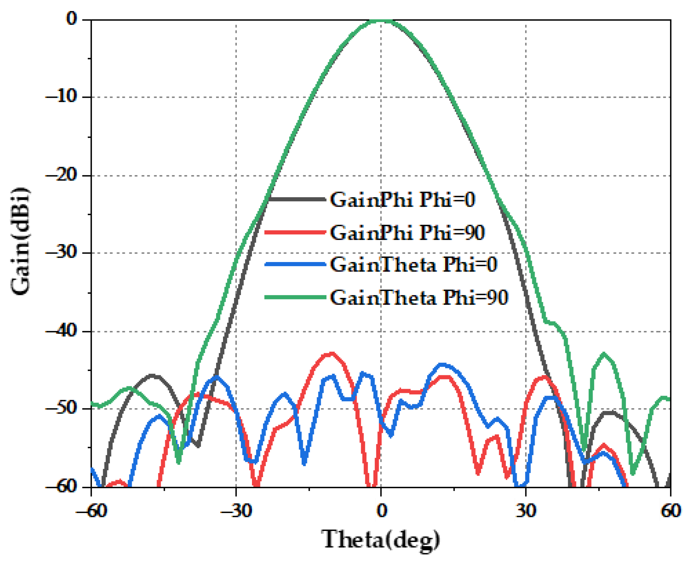
Figure 9.
S band radiation pattern.
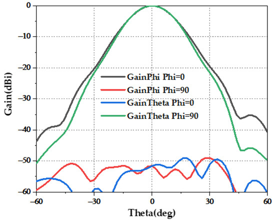
Figure 10.
C band radiation pattern.
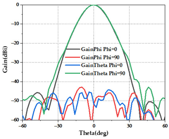
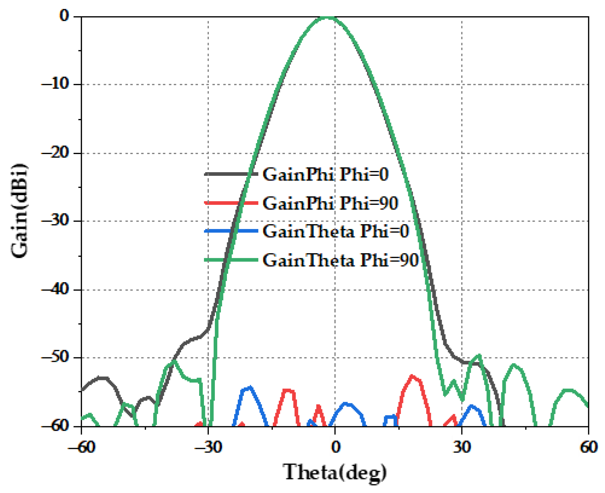
Figure 11.
X band radiation pattern.
It can be observed that, after dielectric loading, the radiation characteristics are good over a wide range of frequency bands. This is true in the frequency bands of L, S, C, and X. The following cross-polarization values are achieved: 51.9 dB (at 0°) (Figure 8) in the L band, 52.8 dB (at 0°) (Figure 9) in the S band, 61.7 dB (at 0°) (Figure 10) in the C band, and 51.6 dB (at 0°) (Figure 11) in the X band.
Due to the selection of the dielectric constant, the modes throughout the whole band are regulated so that it basically works in the HE11 mode; thus, compared with the ridge horn antenna, it has a good directional map in the frequency band, while maintaining a larger bandwidth; in particular, a high frequency will not produce distortion, and the cross-polarization isolation is more stable. Compared with that of the corrugated horn antenna, its working frequency range is much wider, at 1–10 GHz.
Improvement of Dielectric-Loaded Horns
Using the dielectric-loaded material, electromagnetic waves of different frequency bands operate in different regions. The gains and aperture efficiency η are shown in Table 1 below; R stands for the aperture of the horn, Rr stands for the active R for each band, and ηRr stands for the active aperture efficiency calculated with Rr.

Table 1.
Gains, active R and aperture efficiencies.
The aperture efficiency is calculated as follows.
The achievable gains and aperture efficiency are shown in Table 1.
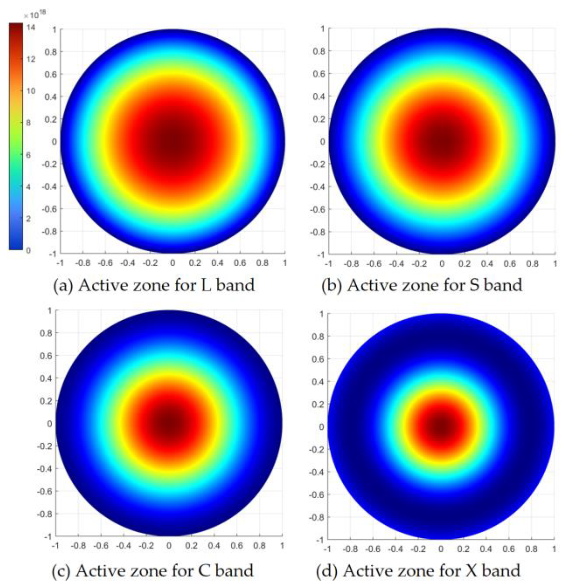
Herein, Rr stands for real active radio. Additionally, Figure 12 shows the active zone for each band.

Figure 12.
Active zones for L/S/C/X band.
From these figures, we can easily observe that, after mode control, the electromagnetic waves at different frequencies have different active radios.
From Table 1, it is obvious that the aperture efficiency calculated with Rr is high enough. However, if we calculated the aperture efficiency with the real radio for the antenna, not only the C band but also the X band was too low.
In order to improve the aperture efficiency, a dielectric cone is loaded over the aperture of the antenna as a director (Figure 13). Here, h1 refers to the height of the horn. With a profiled horn, increasing the height of the horn brings it closer to a balanced mixed mode. On the other hand, h2 represents the height of the director. Once the height of the director surpasses a certain limit, further increases have a minimal impact on performance improvement. However, excessively high horns and directors will make processing more difficult. Thus, after considering processing, h1 is set to 500 mm and h2 is set to 100 mm.
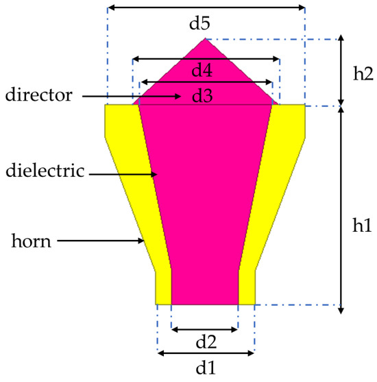
Figure 13.
Structure of director-loaded antenna.
Moving on to the diameter specifications, d1 and d5 represent the lower and upper diameters of the horn, respectively. Similarly, d2 and d3 refer to the lower and upper diameters of the dielectric material. In previous research, we analyzed the hybrid mode in the horn by adjusting the diameter of the dielectric material. Therefore, we adjusted d1/d5 and d2/d3 to achieve a balanced hybrid mode. Consequently, d1 is set to 150 mm, d2 is set to 100 mm, d3 is set to 200 mm, and d5 is set to 300 mm. Additionally, d4 represents the lower diameter of the director, which should cover the active zone for the C and X bands to improve their performance. Hence, d4 is set to 220 mm.
After loading the director, the gain in C band is improved. This is improved to 20.77 dBi. In addition, the gain in the X band is improved in the meantime. This is improved to 24.17 dBi. After these improvements, the aperture efficiencies are improved by 41.5% and 28.7%, respectively. The director works well, and the improvement can be easily observed. Figure 14 and Figure 15 show the improved radiation patterns.
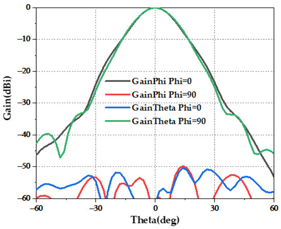
Figure 14.
C band radiation pattern after improvement.
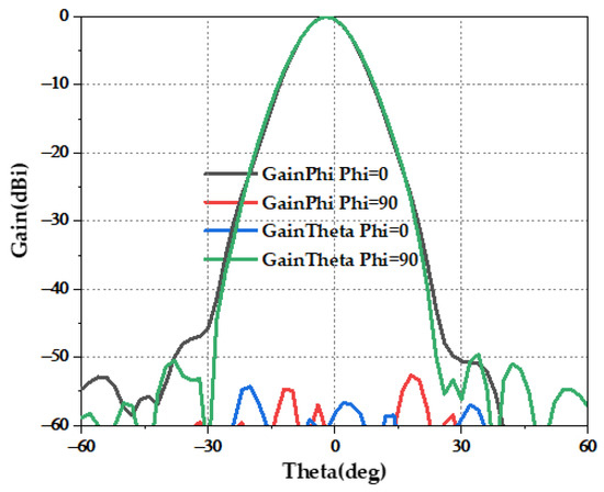
Figure 15.
X band radiation pattern after improvement.
4. Research on Metamaterials
Continuous developments in materials science have laid the foundation for the implementation of dielectric-loaded horn antennas. In the process of achieving broadband operation, it is necessary to comprehensively consider the physical properties and geometric parameters of the dielectric material, such as the dielectric constant, loss tangent, thickness, and shape. These parameters have a significant impact on the performance of the antenna and require optimization and validation to achieve optimum results [30,31,32,33,34].
Through simulation, we can freely choose media with different dielectric constants. However, in practical situations, horn antennas loaded with dielectric materials usually require a highly stable dielectric constant for the loaded medium, and their special shape causes certain difficulties during processing. In consideration of this, it is possible to change the filling rate of the dielectric cell to achieve the desired distribution of dielectric constant. Here, the S parameter inversion method is used to optimize the design of the equivalent dielectric constant of the unit cell.
4.1. S Parameter Retrieval Method
While metamaterials have developed in recent years, they have been mostly represented as examples of effective media. Metamaterial designs typically consist of scattered elements or periodical patterns. In this way, it is convenient to form a metamaterial using design and analysis because the complete numerical solution for Maxwell’s equations can be obtained by considering one unit cell of a periodic structure.
In this study, the metamaterials are also patterned periodically. The cell structure is a diamond. In order to design the diamond-structured metamaterials, the S parameter retrieval method is applied. After computing the transmission matrix T for the metamaterials, the equivalent refractive index n and equivalent impedance Z can be calculated.
The transmission matrix T is shown below.
Within Formula (19), d stands for the thickness of the material structural unit, n stands for the equivalent refractive index, and Z represents impedance.
Then, the S parameter can be calculated using the following equation.
After applying Formulas (20) and (21), the equivalent refractive index n and equivalent Impedance Z can be expressed.
Here, m represents a positive integer. Therefore, the equivalent dielectric constant and equivalent magnetic permeability of the material can be expressed as impedance and the refractive index.
4.2. Design of the Metamaterial
The dielectric constant of the medium inside the horn varies between 1.2 and 1. Thus, we select a resin material with a dielectric constant of 2.8 to achieve the desired properties.
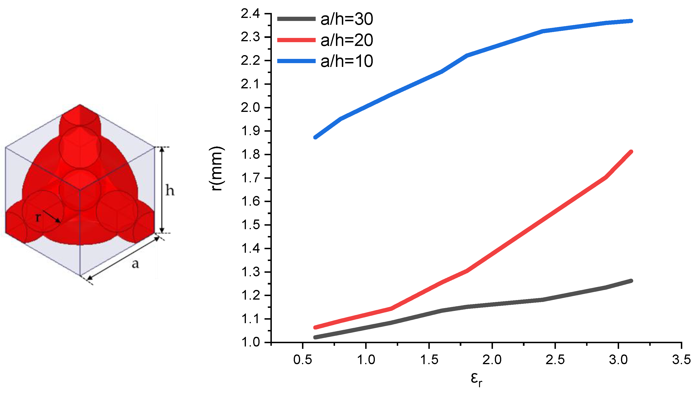
Before applying the S parameter inversion method, we use periodic structural units to fabricate the desired metamaterial. This approach simplified the calculation process and reduced the processing complexity. Subsequently, we apply Floquet ports and primary–secondary boundary conditions to simulate an infinitely large periodic structure array comprised of units, which represent the atomic structure of a diamond, as shown in Figure 16. Here, ‘a’ and ‘h’ describe the size of the unit, while ‘r’ describes the radius of the material. In this work, we varied ‘r’ from 0.6 mm to 3.4 mm to compute the dielectric constant, and ‘a/h’ ranged from 10 mm to 30 mm.

Figure 16.
Unit structure and achievable dielectric constant.
Considering the size of the horn, it is not advisable to use excessively large unit structures, as they would limit the number of units and reduce the achievable range of the dielectric constant. Conversely, using units that are too small would increase the number of units, leading to a higher computational complexity and processing difficulties. Taking these factors into consideration, we chose unit sizes of a = 20 mm and h = 20 mm. We simulate the S parameters, specifically S11 and S21, corresponding to different radii. Subsequently, we apply the S parameter inversion method to calculate the dielectric constant for each radius, as presented in Table 2.
Table 2.
r and dielectric constants εr.
The dielectric constants corresponding to different radii (a/h = 20 mm) are shown in Table 2.
The simulation results (Figure 16) show that, when using a resin material with a dielectric constant of 2.8, the equivalent dielectric constant varies between 2 and 1 at the X band, which meet the dielectric constant requirements of the dielectric-loaded horn. This provides a relatively simple method for subsequent processing and testing.
In order to meet the wideband characteristics of the antenna, its dielectric constant varies less with the frequency throughout the entire frequency band. In Figure 17, the red line represents the real part of εr, and the blue line represents the imaginary part of εr.
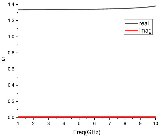
Figure 17.
Dielectric constant within the frequency band.
5. Comparison
After the design and simulation of this dielectric-loaded horn antenna using the metamaterial method, it has an optimum performance compared with those of the ridged horn, multi-band, corrugated horn, and typical dielectric-loaded horn antennas.
The performance comparison of bandwidth, aperture efficiency, and cross-polarization isolation is shown in Table 3.
Table 3.
Comparison of bandwidth, aperture efficiency, and cross-polarization isolation.
In this paper, we propose a type of dielectric-loaded horn using the metamaterial method. With the loaded dielectric material, the performance of the horn antenna has been greatly improved. In Table 3, we use arrows to describe the advantages and disadvantages. The upward arrows represent advantages compared with others, the downward arrow represent disadvantages. We can observe that the ridged horn has a better bandwidth, but worse aperture efficiency and cross-polarization isolation properties. Compared with the ridge horn antenna, which has a 133.3% bandwidth, this antenna can achieve 163.3%. The aperture efficiency of the ridge horn antenna is 28–49%, which is 95% in the L band, 65.4% in the S band, 41.5% in the C band, and 28.7% in the X band in this work. The cross-polarization isolation value for ridge horn antenna is higher than 6 dB, and it is higher than 51.6 dB in this study. Compared with multi-band antennas, the bandwidth for each band is less than 20%, and the bandwidth in this work is much larger. In the X band, the multi-band antennas’ aperture efficiency is 34% which is higher than that in this study (28.7%), but it is 53% in the L band, which is lower than that in this study (95%). The cross-polarization isolation value for the multi-band antenna is larger 30 dB, and it is lower than 51.6 dB in this paper. For the corrugated horn, the bandwidth is 28.6%, which is lower than the one in this paper. However, the aperture efficiency performance is good, being higher than 66.8%. The cross-polarization isolation performance (≥30 dB) is not as good as that in this study. A typical dielectric-loaded horn presents a method of loading a dielectric material in a horn. This works only to improve the point frequency, and the aperture efficiency (32%) is not high. However, because of the balanced HE11 mode, the cross-polarization isolation value (≥60 dB) is high enough.
The comparison showed that the dielectric-loaded horn antenna expanded its bandwidth like the ridge horn, and it has a high cross-polarization isolation value like the corrugated horn. The aperture efficiency is high in the L band, and it is improved by the director.
6. Experiments and Data Analysis
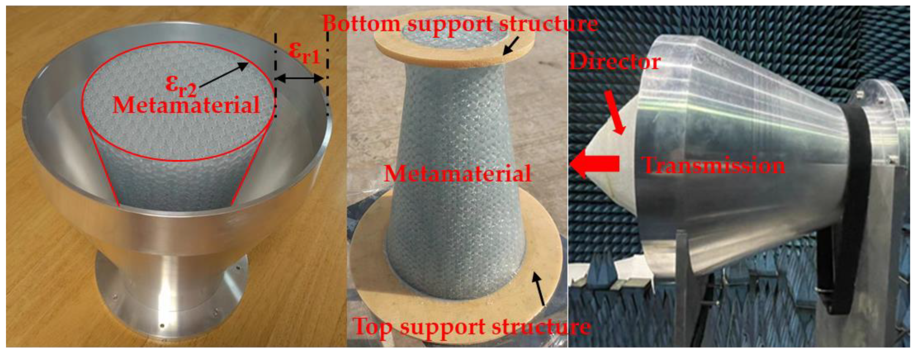
After the simulation, it was necessary to validate the performance of the dielectric-loaded horn antenna. To accomplish this, the VSWR of the antenna was measured using a vector network analyzer. Additionally, the radiation patterns of the antenna at the L, S, C, and X bands were measured in a microwave measurement darkroom at Xi’an University of Electronic Science and Technology. The antenna far field measurement system used for this purpose was XD-2. For reference, a photograph of the dielectric-loaded horn antenna is shown below.
As shown in Figure 18, it appears that the metamaterial with εr2 is loaded in the center of the horn, while the remaining space in the horn is filled with air (εr1). Additionally, the director is loaded on top of the horn.
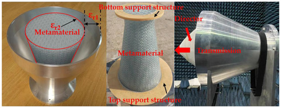
Figure 18.
Photograph of the dielectric-loaded horn antenna.
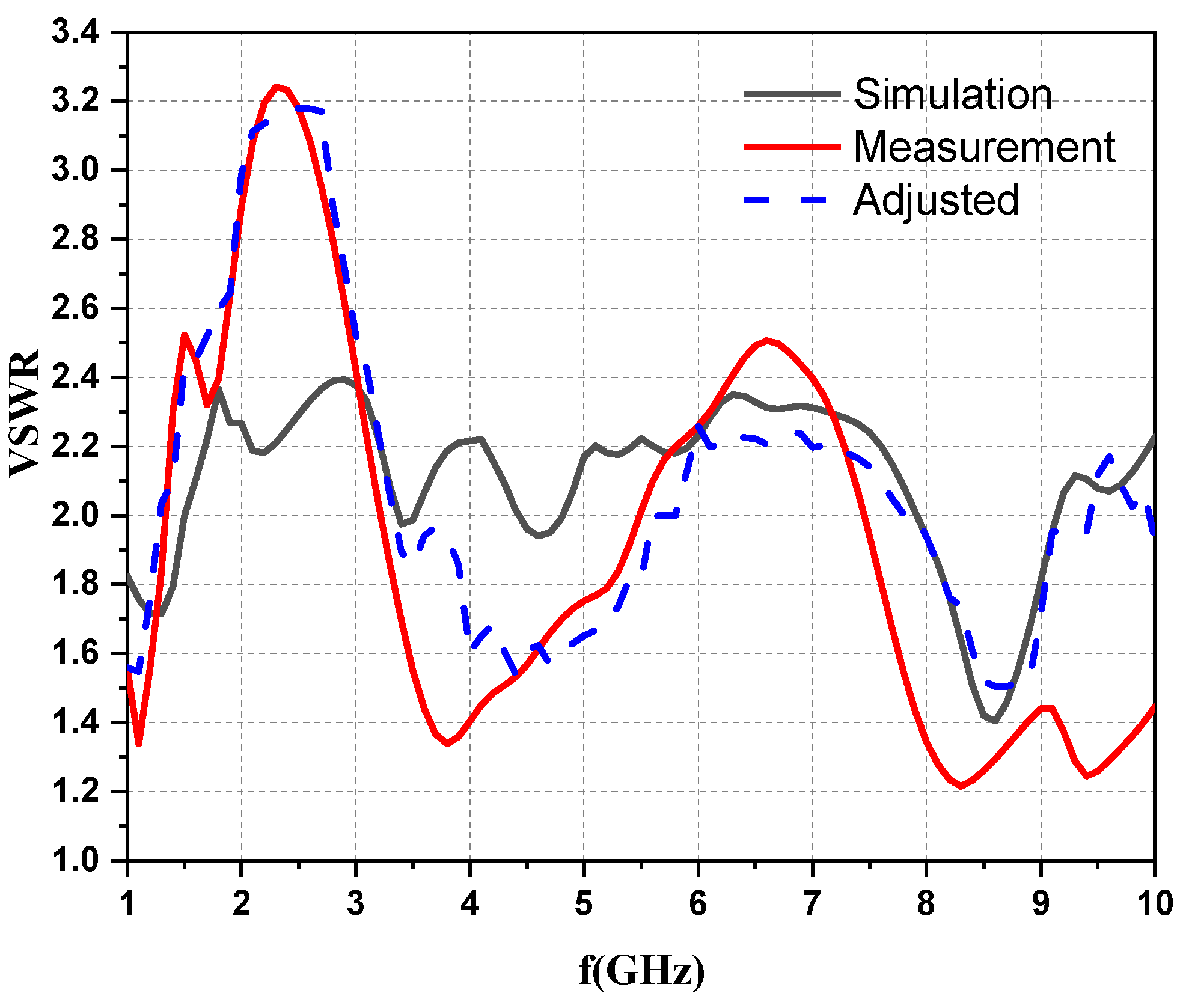
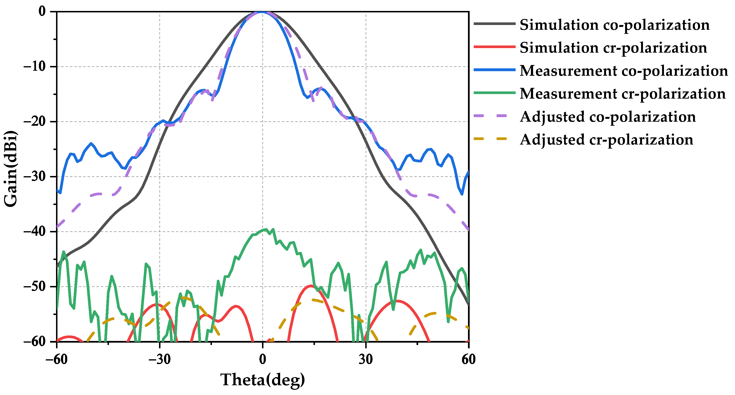
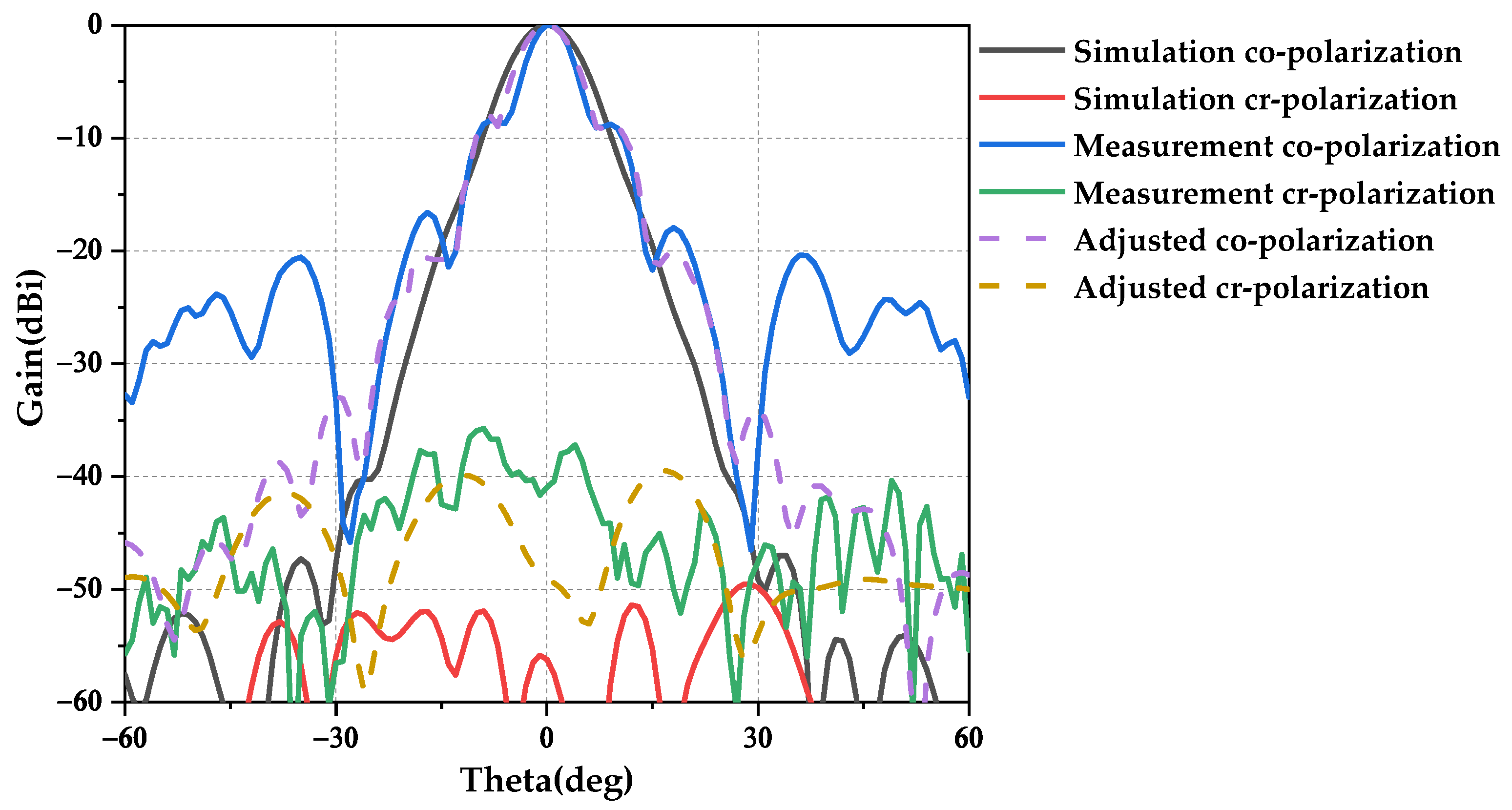
Initially, the VSWR of the horn is measured using a two-port vector network analyzer (R&S ZVK20), as shown in Figure 19. It was noted that, in the simulation, the influence of supporting structures on the VSWR and radiation patterns was not considered. Subsequently, adjustments were made to the simulation to incorporate the influence of supporting structures on the VSWR and radiation pattern. The adjusted simulation results were then compared with the original simulation results, and the measurement results are shown in Figure 19, Figure 20, Figure 21, Figure 22 and Figure 23.
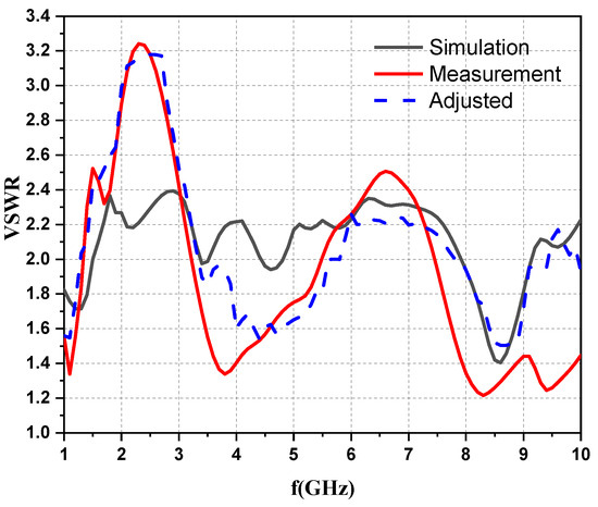
Figure 19.
Measured and simulated VSWRs.
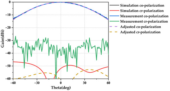
Figure 20.
L band measured and simulated radiation patterns.
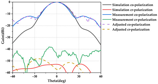
Figure 21.
S band measured and simulated radiation patterns.
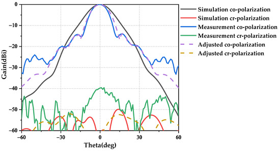
Figure 22.
C band measured and simulated radiation patterns.
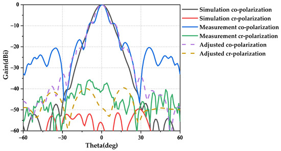
Figure 23.
X band measured and simulated radiation patterns.
Observing Figure 19, it is apparent that the measurement results of the VSWR validated the adjusted simulation results. The trend observed in the measurements aligns closely with the VSWR results from the adjusted simulation. Discrepancies between the measured and adjusted results are attributed to processing errors associated with the metamaterial.
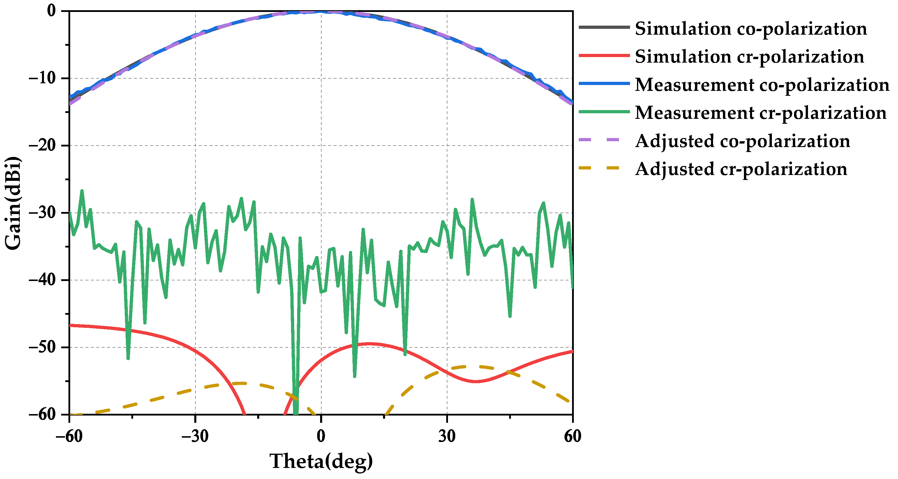
For the accuracy of the radiation pattern in each band, the phase center of both the measure and measured antennas should be aligned. The measured radiation patterns of the dielectric-loaded horn antenna are shown in Figure 20, Figure 21, Figure 22 and Figure 23. Far-field measurements are taken of the radiation patterns (horizontal plane).
As shown in Figure 20, Figure 21, Figure 22 and Figure 23, the measured gain is 10.6 dBi, the aperture efficiency is 80.9%, and the cross-polarization isolation value is 41.8 dB in the L band. The measured gain is 17.6 dBi, the aperture efficiency is 57%, and the cross-polarization isolation value is 45.7 dB in the S band. The measured Gain is 18.2 dBi, the aperture efficiency is 23%, and the cross-polarization isolation value is 39.7 dB in the C band. The measured gain is 21.8 dBi, the aperture efficiency is 16.7%, and the cross-polarization isolation value is 40.9 dB in the X band. Observing these results, it can be seen that the experimental results closely align with the adjusted simulation results in the L band. In the S band, the experimental results are comparable to the adjusted simulation results within the main lobe range. Furthermore, the results observed in the C and X bands are consistent with those recorded in the S band. However, the cross-polarization isolation value for all the bands is ≥39 dB, which is sufficient for most applications. Considering the measurement errors, after comparison with the adjusted simulation results, the experimental results are dependable.
7. Conclusions
In this paper, we propose a dielectric-loaded horn antenna, in which a metamaterial is applied to expand the bandwidth and make it work in the HE11 mode. After loading the dielectric material, the bandwidth expands from the L band to X band. In each band, there is no distortion in the radiation patterns. The radiation patterns have no apical depression and no offset pointing. In the meantime, the cross-polarization isolation value is over 51.6 dB.
After placing the director over the aperture, the aperture efficiency is improved in the C and X bands. Considering this realization, a metamaterial is applied to achieve a stable dielectric constant. With these simulations and experiments, the feasibility of the proposed dielectric-loaded horn antenna has been proved.
Author Contributions
Methodology, B.Z.; software simulation and validation, B.Z.; fabrication and measurement, B.Z., W.D., N.L. and G.F.; writing original draft preparation, B.Z. All authors have read and agreed to the published version of the manuscript.
Funding
This research received no external funding.
Data Availability Statement
All data have been included in the study.
Conflicts of Interest
The authors declare no conflict of interest.
References
- Pyle, J.R. The Cutoff Wavelength of the TE/sub 10/ Mode in Ridged Rectangular Waveguide of Any Aspect Ratio. IEEE Trans. Microw. Theory Tech. 1966, 14, 175–183. [Google Scholar] [CrossRef]
- Oktafiani, F.; Hamid, E.Y.; Munir, A. Experimental Validation of Dual-Polarized Aluminium-based Ridged Horn Antenna. In Proceedings of the 2021 IEEE Asia Pacific Conference on Wireless and Mobile (APWiMob), Bandung, Indonesia, 8–9 April 2021; pp. 151–154. [Google Scholar]
- Zhao, Z.; Wang, Z.; Kelly, J.R.; Gao, S. Balanced Feed Low Cross-Polarization Quad-Ridged Horn Antenna with Center Cross Fusiform Loaded. IEEE Trans. Antennas Propag. 2021, 69, 6004–6009. [Google Scholar] [CrossRef]
- Yue, Z.; Liu, Y.; Zhu, P. Design of a Miniaturized Double Ridged Horn Antenna. In Proceedings of the 2019 International Symposium on Antennas and Propagation (ISAP), Xi’an, China, 27–30 October 2019; pp. 1–2. [Google Scholar]
- Lin, T.-C.; Lee, C.-H.; Hsieh, M.-K.; Chiu, C.-N.; Lin, D.-B.; Lin, H.-P. A Broadband Double Ridged Horn Antenna for Radiated Immunity and Emissions Test from 18 GHz to 50 GHz. In Proceedings of the 2021 7th International Conference on Applied System Innovation (ICASI), Chiayi, Taiwan, 24–25 September 2021; pp. 63–66. [Google Scholar]
- Asok, A.O.; Gokul Nath, S.J.; Dey, S. Double Ridge Horn Antenna with Curved Dielectric Loading for Microwave Imaging Applications. In Proceedings of the 2021 IEEE Indian Conference on Antennas and Propagation (InCAP), Jaipur, Rajasthan, India, 13–16 December 2021; pp. 167–170. [Google Scholar]
- Liu, S.; Liu, J.; Zhao, L.; Yuan, C.; Hu, N.; Xie, W. The Design of UWB Double-Ridge Horn Antenna. In Proceedings of the 2020 9th Asia-Pacific Conference on Antennas and Propagation (APCAP), Xiamen, China, 4–7 August 2020; pp. 1–2. [Google Scholar]
- Ronshu, Z.; Guizhen, L.; Qingxin, G.; Dongdong, Z.; Zhi, C.; Chao, C. Optimization of Corrugated Profiled Horn with Low Cross-polarization. In Proceedings of the 2017 IEEE 5th International Symposium on Electromagnetic Compatibility (EMC-Beijing), Beijing, China, 28–31 October 2017; pp. 1–3. [Google Scholar]
- Gonzalo, R.; Teniente, J.; del Rio, C. Improved Radiation Pattern Performance of Gaussian Profiled Horn Antennas. IEEE Trans. Antennas Propag. 2002, 50, 1505–1513. [Google Scholar] [CrossRef]
- Teniente, J.; Goni, D.; Gonzalo, R.; del-Rio, C. Choked Gaussian Antenna: Extremely Low Sidelobe Compact Antenna Design. IEEE Antennas Wirel. Propag. Lett. 2002, 1, 200–202. [Google Scholar] [CrossRef]
- Chen, Y.-C.; Zhou, Y.-G.; Xu, T.; Jiang, H.-Z.; Zhao, Y.-J.; Wang, H.-Z.; Yang, H.-M. Dual-polarized Improved Gaussian Profiled Corrugated Horn Antenna with Low Cross-Polarization. In Proceedings of the 2021 International Conference on Microwave and Millimeter Wave Technology (ICMMT), Nanjing, China, 23–26 May 2021; pp. 1–3. [Google Scholar]
- Zhang, R.; Lu, G. Design of Corrugated Horn with Low Cross-Polarization and Wide Band for Satellite Applications. In Proceedings of the 2021 26th IEEE Asia-Pacific Conference on Communications (APCC), Kuala Lumpur, Malaysia, 10–13 October 2021; pp. 179–184. [Google Scholar]
- Rahardiyanti, K.; Zulkifli, F.Y.; Rahardjo, E.T. Design of Corrugated Horn Antenna for Electronic Support Measure Application. In Proceedings of the 2020 International Conference on Radar, Antenna, Microwave, Electronics, and Telecommunications (ICRAMET), Tangerang, Indonesia, 18–20 November 2020; pp. 159–162. [Google Scholar]
- Lin, W.; Zhang, Z.-Y.; Fu, G. Design of a High Gain and Low Cross-Polarization Tri-Band Horn Antenna. In Proceedings of the 2018 International Conference on Microwave and Millimeter Wave Technology (ICMMT), Chengdu, China, 7–11 May 2018; pp. 1–3. [Google Scholar]
- Kabir, S.S.; Khan, M.H.; Latif, S.I. A Multi-Band Circularly Polarized-Shared Aperture Antenna for Space Applications at S and X Bands. Electronics 2023, 12, 4439. [Google Scholar] [CrossRef]
- Maddio, S.; Nesti, R.; Pelosi, G.; Righini, M.; Selleri, S. Profiled Corrugated Horn for Compact and High Efficiency Feeds. In Proceedings of the 2018 International Conference on Electromagnetics in Advanced Applications (ICEAA), Cartagena, Colombia, 10–14 September 2018; pp. 675–678. [Google Scholar]
- Olver, A.D.; Pearson, R.A.; Peake, G.E.J.; Philips, B. Metallised Dual Dielectric Loaded Horn. In Proceedings of the 1991 Seventh International Conference on Antennas and Propagation, ICAP 91 (IEE), York, UK, 15–18 April 1991; Volume 1, pp. 121–124. [Google Scholar]
- Olver, A.D.; Philips, B. Profiled Dielectric Loaded Horns. In Proceedings of the 1993 Eighth International Conference on Antennas and Propagation, Edinburgh, UK, 30 March–2 April 1993; Volume 2, pp. 788–791. [Google Scholar]
- Clarricoats, P.J.B.; Olver, A.D.; Raghavan, K. Mode Conversion in Dielectric Loaded Horn. In Proceedings of the 1988 IEEE AP-S. International Symposium, Antennas and Propagation, Syracuse, NY, USA, 6–10 June 1988; Volume 1, pp. 362–365. [Google Scholar]
- Raghavan, K.; Olver, A.D.; Clarricoats, P.J.B. Compact Dielectric Feeds for Prime Focus Reflector Antennas. In Proceedings of the 1988 IEEE AP-S. International Symposium, Antennas and Propagation, Syracuse, NY, USA, 6–10 June 1988; Volume 1, pp. 350–353. [Google Scholar]
- Olver, A.D.; Clarricoats, P.J.B. Dielectric Cone Loaded Horn Antennas. IEEE Proc. Microw. Antennas Propag. 1988, 135, 158–162. [Google Scholar] [CrossRef]
- Kumar, A. Dielectric-loaded horn feeds for radiometer antenna. In Proceedings of the Digest on Antennas and Propagation Society International Symposium, San Jose, CA, USA, 26–30 June 1989; Volume 3, pp. 1424–1426. [Google Scholar]
- Wang, D.; Liu, Y.; Liang, J. Design of a Crossed Dielectric Resonator-Loaded, Dual-Band Dual-Polarized Differential Patch Antenna with Improved Port Isolation and Gain. Electronics 2023, 12, 3570. [Google Scholar] [CrossRef]
- Akagi, Y.; Deguchi, H.; Tsuji, M. A Multi-Band Dielectric-Loaded Horn Antenna with Two Feed Systems. In Proceedings of the 2019 International Conference on Electromagnetics in Advanced Applications (ICEAA), Granada, Spain, 9–13 September 2019; pp. 0667–0669. [Google Scholar]
- Hiratsuna, A.; Akagi, Y.; Deguchi, H.; Tsuji, M. Dielectric Loaded Coaxial Grooves Horn with Ku/Ka feed systems for Low Cross Polarization use. In Proceedings of the 2018 International Symposium on Antennas and Propagation (ISAP), Busan, Republic of Korea, 23–26 October 2018; pp. 1–2. [Google Scholar]
- Philips, B.; Olver, A.D. Design and Performance of Profiled Dielectric Loaded Horns. Proc. IEEE—Microw. Antennas Propag. 1994, 141, 337–341. [Google Scholar] [CrossRef]
- Balanis, C.A. Advanced Engineering Electromagnetics; Wiley: Hoboken, NJ, USA, 1989; pp. 483–540. [Google Scholar]
- Zhu, L.; Liu, N.-W. Multimode Resonator Technique in Antennas: A Review. Electromagn. Sci. 2023, 1, 0010041. [Google Scholar] [CrossRef]
- Veselago, V.G. The electrodynamics of substance with simultaneously negative values of ε and μ. Sov. Phys. Uspekhi 1968, 10, 509–514. [Google Scholar] [CrossRef]
- Pendry, J.B.; Holden, A.J.; Robbins, D.J.; Stewart, W.J. Magnetism from Conductors and Enhanced Nonlinear Phenomena. IEEE Trans. Microw. Theory Tech. 1999, 47, 2075–2084. [Google Scholar] [CrossRef]
- Smith, D.R.; Padilla, W.J.; Vier, D.C. Composite Medium with Simultaneously Negative Permeability and Permittivity. Phys. Rev. Lett. 2000, 84, 4184–4187. [Google Scholar] [CrossRef] [PubMed]
- Smith, D.R.; Vier, D.C.; Koschny, T.; Soukoulis, C.M. Electromagnetic Parameter Retrieval from Inhomogeneous Metamaterials. Phys. Rev. E Stat. Nonlinear Soft Matter. Phys. 2005, 3, 71. [Google Scholar] [CrossRef] [PubMed]
- Chen, X.; Grzegorczyk, T.M.; Wu, B.-I.; Pacheco, J.J.; Kong, J.A. Robust method to retrieve the constitutive effective parameters of metamaterials. Phys. Rev. E 2004, 70, 016608. [Google Scholar] [CrossRef]
- Zhao, B. Design of Luneburg Lens Antennas Based on Electromagnetic Metamaterials; Xidian University: Xi’an, China, 2021; pp. 21–23. [Google Scholar]


Disclaimer/Publisher’s Note: The statements, opinions and data contained in all publications are solely those of the individual author(s) and contributor(s) and not of MDPI and/or the editor(s). MDPI and/or the editor(s) disclaim responsibility for any injury to people or property resulting from any ideas, methods, instructions or products referred to in the content. |
© 2024 by the authors. Licensee MDPI, Basel, Switzerland. This article is an open access article distributed under the terms and conditions of the Creative Commons Attribution (CC BY) license (https://creativecommons.org/licenses/by/4.0/).