Article

Three-Dimensional Digitization of Documentation and Perpetual Preservation of Cultural Heritage Buildings at Risk of Liquidation and Loss—The Methodology and Case Study of St Adalbert’s Church in Chicago

Department of Computer Science, Lublin University of Technology, 20-618 Lublin, Poland
*
Author to whom correspondence should be addressed.
Electronics 2024, 13(3), 561; https://doi.org/10.3390/electronics13030561
Submission received: 13 January 2024 / Revised: 26 January 2024 / Accepted: 28 January 2024 / Published: 30 January 2024

Abstract

:
This paper presents a three-dimensional (3D) digitization methodology for documenting the appearance and geometry of cultural heritage buildings using modern tools for data acquisition and processing. This work presents a method combining laser scanning of building dimensions with photographic texture acquisition techniques in order to develop accurate, photo-realistic 3D models. This work also presents a method for digital reconstruction of the elements of interiors. This case study presents the process and result of scanning the church of St Adalbert in Chicago along with its inner finishing elements, achieved during the interventional 3D scanning of a historical building interior. The obtained colorized point cloud has 3.5 billion points and a volume of 65 GB. Its creation took nearly 3.5 h on a high-end computer. The generated textured mesh model has 1.6 billion triangles and a volume of 60 GB. The analysis of the results showed that the elements of the church furnishings were reproduced with very high accuracy. The developed 3D model of the interior, appearance and dimensions of the church is its perpetual documentation. It can be used for various purposes, such as popularizing the appearance on the Internet, scientific research on interior artefacts, creating files for VR and shooting high-resolution films.

1. Introduction

In the area of tangible cultural heritage in the modern world, two opposing trends can be observed. On the one hand, thanks to the persistent and systematic work of archaeologists, art historians and conservators, the number and condition of historic buildings are increasing. On the other hand, due to emerging natural cataclysms, such as earthquakes, floods and tsunamis, climate changes, such as the filling of inhabited areas by increasingly expanding deserts and steppification of agricultural areas, and cataclysms caused by people, such as wars, fires, thefts, deliberate destruction (act of revenge against conquered nations) and the demolition of currently unnecessary architectural structures, e.g., in order to obtain cheap construction materials or acquire new areas for various infrastructure investments, the number of cultural heritage objects are decreasing and they are at risk of destruction [1].
This work presents three-dimensional (3D) computer technologies, namely, terrestrial laser scanning (TLS) and terrestrial short-range photogrammetry (TSRP), as effective solutions for permanent perpetual 3D archiving of tangible cultural heritage objects. The term 3D perpetual archiving is understood here as a method of data acquisition (surface coordinates, object dimensions and colors and textures of archived objects) which can save data in digital form in formats available for many different programs for subsequent (time-unlimited) repeated post-processing and use, according to the development of software capabilities and hardware computing power.
This article presents a set of activities for the case of interventional 3D scanning which concerns the interior of the Catholic church of St Wojciech (St Adalbert) in Chicago. This church, dating from the beginning of the 20th century, has already been excluded from liturgical use and is subject to a process of gradual degradation, including the dismantling and removal of elements of its furnishings. Through interventional 3D scanning, the authors understand a situation in which there is only one chance to document the dimensions and appearance of an object by carrying out 3D scanning processes. This means that in this activity, there are limited resources time, human, hardware and IT available to perform all necessary activities to make the data acquisition as complete and as accurate as possible.
The aim of this article is to present a coherent 3D scanning methodology using 3D TSL and TSRP in the conditions of intervention 3D scanning during a research expedition whose task was the 3D digitization of the material sacred heritage of the Polish diaspora in the USA. The quality of the applied methodology was indirectly verified by post-processing of the collected data and presenting them in the form of mesh models of scanned interiors and objects, as the so-called base models, and in the form of reduced-size models, which are available on the website: polishheritage3d.com (accessed on 10 January 2024). A detailed analysis of the scanning accuracy carried out for the church’s interior objects showed a very high accuracy of their mapping in the form of a 3D mesh model.

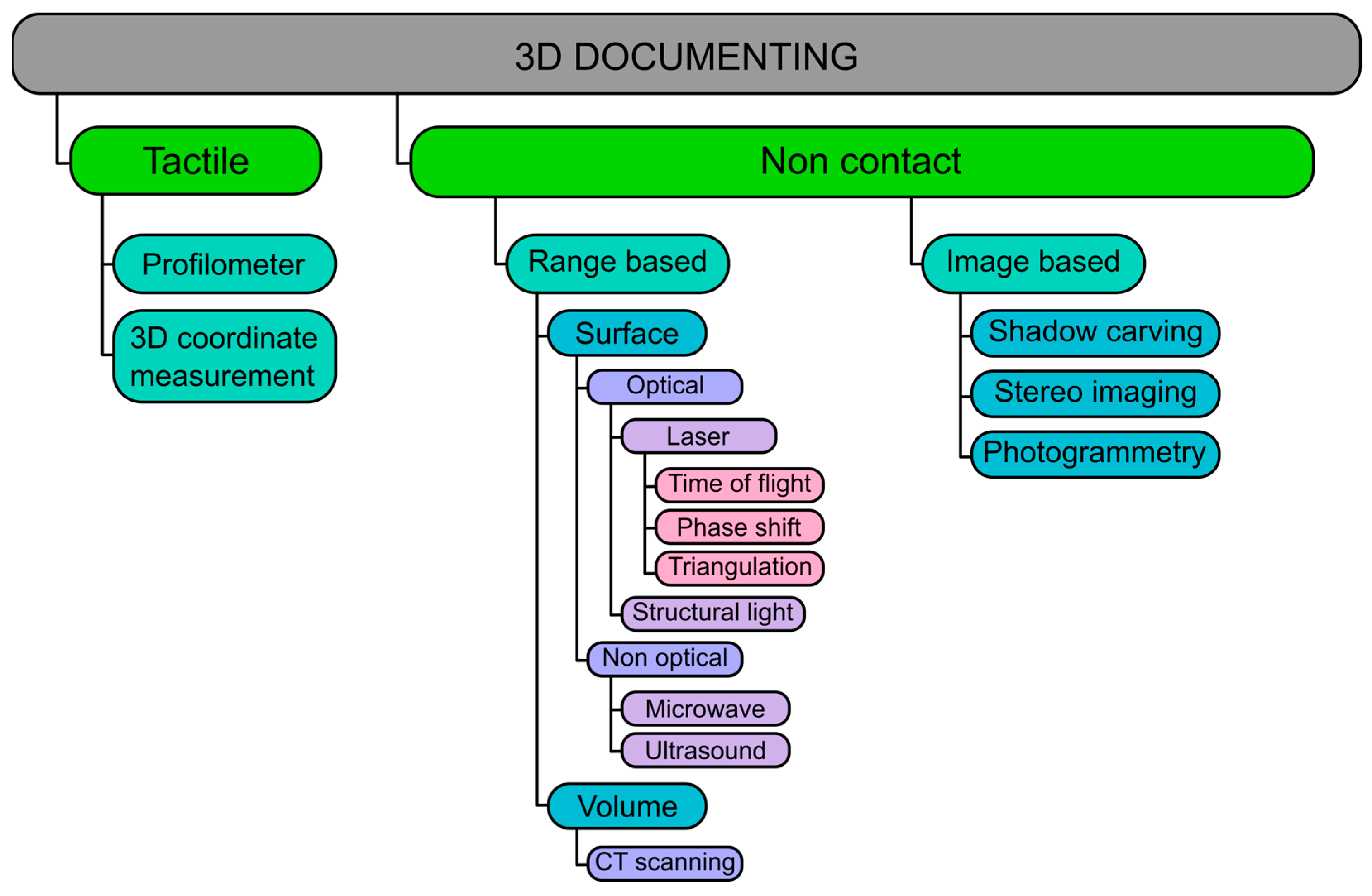
2. Literature Review

In recent years, the 3D scanning process has become a technology quite widely known and used in the area of archiving tangible cultural heritage in many regions of the world. The author in [2] points out that obtaining digital 3D models allows for wear measurements of the external structure of the object and analysis of its surfaces and their colors. This applies to both small museum objects [3,4,5,6,7], sculptures and statues [8,9,10], as well as large architectural objects [11,12,13,14,15,16] or archaeological sites [17,18,19,20,21,22]. Data acquisition activities in 3D technology are carried out by various scientific and research communities representing many research centers in Europe (Italy, Spain, United Kingdom, France, Germany and Portugal, but also recently in Poland and Romania) and across the world: China, the USA, Australia, Japan and recently also Egypt, Iran and Uzbekistan [23]. Some of the work is carried out during typical scientific expeditions, during which scientists and their equipment travel many thousands of kilometers to an area that is geographically, culturally, linguistically and religiously foreign to archive the world’s cultural heritage. During such expeditions, their participants also try to transfer knowledge and competences by organizing and conducting scientific and practical seminars [24] for local scientific communities, museologists and administration representatives.
Three-dimensional scanning of small historical objects leads, in the vast majority of cases, to the production of their digital 3D models available in the form of virtual 3D museums on Internet portals [25,26], less often in the form of a museum in VR or AR technology [27,28,29,30] and occasionally in the form of copies of 3D models printed on 3D replicators [31,32,33,34]. Due to the fact that this article concerns primarily the acquisition of 3D data of large architectural objects and large sculptures, a detailed literature review will focus on this technique, i.e., scanning with TLS and TSRP and hybrid data fusion at the post-processing stage.
The systematics of 3D scanning methods are described in both [8,23], as shown in Figure 1.
Among the works on the digitization of architectural objects, most of them concern 3D scanning of the external structure [11,13,14,15,16], and only some refer to the interior [1,35,36].
The issues of integration of both technologies (i.e., TLS and TSRP) presented with specific examples from the area of cultural heritage have appeared systematically since the beginning of the 21st century: [19]—Greek vessel, Ref. [37]—ways of integrating small museum objects and architectural objects (doctoral thesis), Refs. [17,21]—archaeological sites and excavations, and Ref. [38]—religious complex Staffarda Abbey (Piedmont, Italy). There are also several articles that are reviews [39,40,41]. In the initial period, TLS technology was treated as a complement to close range photogrammetric (CRP) techniques [39]. This work distinguished three approaches to integrating images and scans: data fusion (data from sensors to create synthetic perspective images), image fusion (synthetic perspective images and intensity images), and model-based image fusion (2D intensity image and 3D geometric model). In [40], it was pointed out that the essence of integration is to compensate for the individual disadvantages of each method. This article presents four levels of integration:
  • At the object level;
  • Laser scanning assisted photogrammetry;
  • Photogrammetry-assisted laser scanning;
  • Closely integrated laser scanning and optical imaging.
It should be noted that modern TLS devices implement this last approach automatically, which allows us to obtain 3D digital models with the characteristics of realistic models. Work [41] describes the advantages and disadvantages of three categories of methods for geometric integration of images and laser scanning data: TLS data used for image control, images used as checks for TLS data, and joint regulation of TLS imagery and data.
In all of the works mentioned, the integration of photogrammetric data and data from the scanning process concerned the creation of digital 3D cloud models of architectural objects, sometimes together with their surroundings, or small museum objects. Only in [42] did the authors, after 6 days of data acquisition with both technologies, integrate them to obtain digital 3D mesh models of both the architectural object and the details of its interior design. However, the obtained interior details were of quite low quality, and the calculations performed on available equipment took about 120 h. In [15], the authors used TLS and TSRP technology and short-range airborne photogrammetry (SRAP) by using an unmanned aerial vehicle (UAV) to obtain a 3D model of the Darvas-La Roche House (Oradea, Romania). They integrated the acquired data into one digital 3D model, obtaining a good quality model. Only photogrammetry was used to generate a 3D model of the interior, and models of individual rooms in the building were introduced into VR, creating a digital museum.
From the perspective of the work performed in the present article, important information can be found in [8]. The authors carried out 3D digitization of the historic figure of the Holy Christ of the Blood in the conservation studio using three different technologies: TLS (FARO S150 scanner made by FARO Technologies, Inc., Lake Mary, FL, US), TSRP (Sony Alpha 7R camera made by Sony Group Corporation, Tokyo, Japan) and scanning using Structured Light Scanning (SLS) technology—Artec Eva 3D scanner made by Artec Europe, S.a.r.l., Luxembourg. The results obtained indicate that in this situation, the best 3D digital models were obtained using the Artec Eva scanner and photogrammetry. It was also confirmed that laser scanning is suitable for digitizing sculptures but requires proper selection of scanning parameters and the number of exposures. However, this work only involved scanning a single sculpture in a controlled environment.

3. Motivation

3.1. Historical and Social Context

Contemporary demographic changes and constant migration of people, so characteristic of American society, mean that many religious complexes (consisting of a church, rectory, school buildings, educational buildings, chapels and various commemorative monuments) built at the turn of the 19th and 20th centuries are at risk, and also those created up until the 1930s. Many of these facilities were funded by believers belonging to specific national communities, e.g., Poles, Irish, Germans or Mexicans. Newcomers arrived here bringing their traditions, religions and priests. In the interwar period, Chicago was the second city in terms of the number of Polish people living there (after Warsaw, and before Kraków, Poznań, Lwów and Wilno). This fact meant that the number of Polish churches in Chicago were huge.
The process of increasing the wealth of the Polish population, leading to many leaving traditional districts and moving to the outskirts of the city to more modern houses, structural changes in the development of Chicago and the observed process of decreasing the number of individual families (fewer children), resulted in the maintenance of all Polish churches and religious complexes becoming more difficult. There was a process of merging parishes, transferring churches to the care of priests who no longer represented Polish expat or Polish communities, and transferring churches to other Catholic communities, e.g., those representing residents from Mexico. Finally, there was a process of desacralization of church buildings, i.e., their exclusion from religious functions. This process leads, in later stages, to the reconstruction of buildings, including former churches, for new needs, e.g., concert halls, exhibition halls, clubs or their complete demolition.

3.2. Archiving and Dissemination Context

Sacred complexes from the turn of the 19th and 20th centuries, although they are not included in the list of monuments, are very interesting objects in terms of architecture—understood as the entire structure—and interior design: altars, sculptures, pulpits, stained glass windows, organs and paintings. Modern 3D computer technologies enable an effective process of 3D digitization of the interiors of buildings, along with all elements of their equipment, which allows them to be transferred entirely to the digital world. Therefore, it is possible to carry out two processes simultaneously: perpetual 3D archiving in the form of the so-called point clouds and series of photographs, and making objects in the digital world widely available to the public, such as in the form of interactive 3D models, 3D panoramas, 3D mesh models, videos of digital camera flights over a 3D model, and digital 3D reconstructions, introducing the observer to the world of VR, or building AR models. Thanks to the three-dimensional digitization of objects whose existence is at risk, their appearance and dimensions will be preserved for future generations in a modern form. Digital sharing on dedicated portals and specialized repositories is the cheapest form of sharing the world heritage of various nations with the international community. Moreover, this form of access counteracts the economic exclusion of poor people (economic exclusion) as well as the exclusion of disabled people (digital tourism).

3.3. The Project

The project “Research on the national cultural heritage of the Polish community in the US and the creation of digital memory collections” (grant no.: NdS/545613/2022/2022) is implemented in 2022–2024 by the ECCC Foundation as a part of the program of the Polish Minister of Education and Science “Science for Society” in the area “Humanities-Society-Identity” (https://polishheritage3d.eu/, accessed on 10 January 2024).
The aim of the project is to acquire and preserve in the digital space the cultural heritage of the Polish community in the US (including those threatened with extinction due to demographic reasons) and its popularization. The project envisages the implementation of scientific expeditions to the USA in order to 3D scan at least 15 churches built by the Polish community abroad, as well as the organization of three scientific exhibitions, the development and maintenance of an internet portal with the results of this work (including digital memory collections and historical data on objects) and the development and the publication of two scientific monographs (one in each of the areas of computer science and humanities).
The interdisciplinary project team is formed from ECCC Foundation employees and two scientific teams:
  • The first: IT specialists from the Lublin University of Technology, Poland (Department of Computer Science, Lab3D Laboratory);
  • The second: historians from the John Paul II Catholic University of Lublin, Poland (Centre for Research on Polish Diaspora and Chaplaincy Polonia).
As part of the project, two research expeditions to the US have already been carried out:
  • The first scientific expedition to the US during 9–23 October 2022;
  • The second scientific expedition to the US during 26 June–10 July 2023.
During the second scientific expedition, it was possible to organize an emergency 3D scanning of the interior of the Catholic church of St Adalbert in Chicago, which (despite attempts to do so) was not achieved during the first scientific expedition.

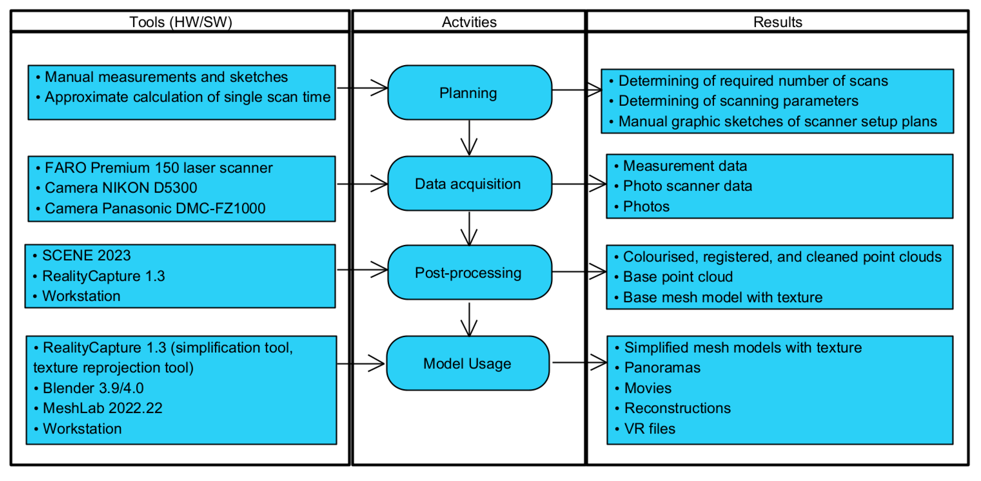
4. Materials and Methods

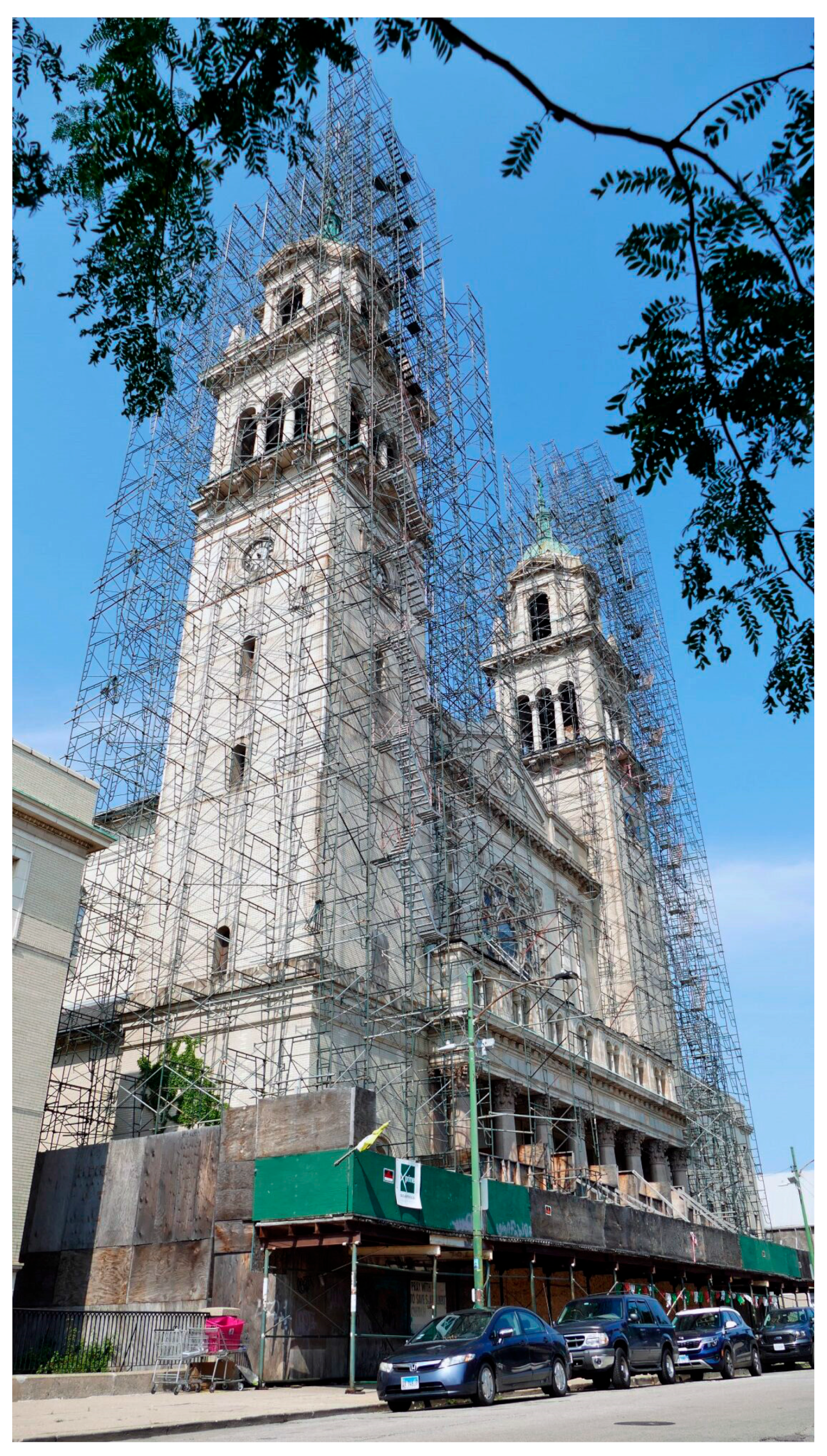
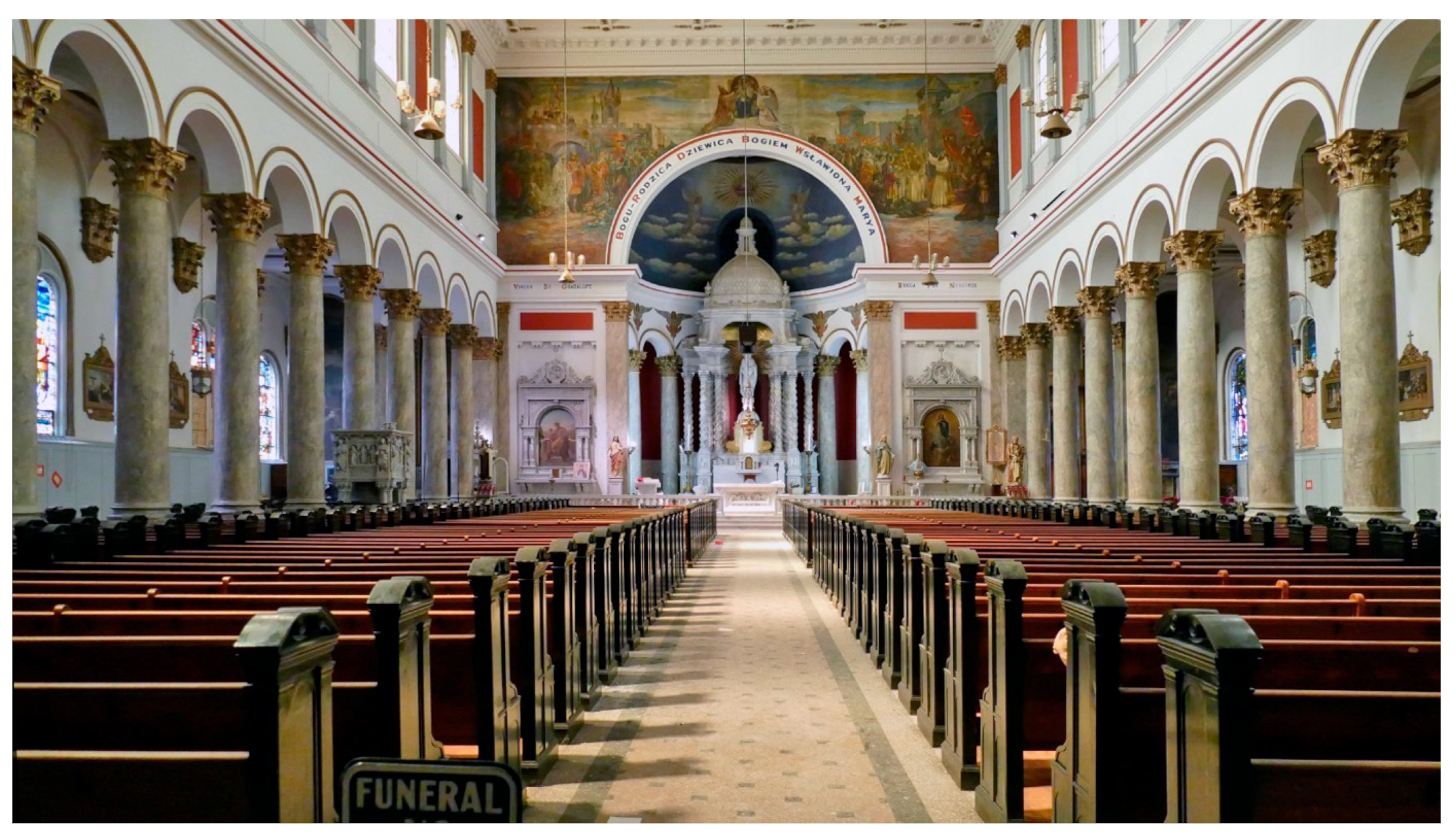
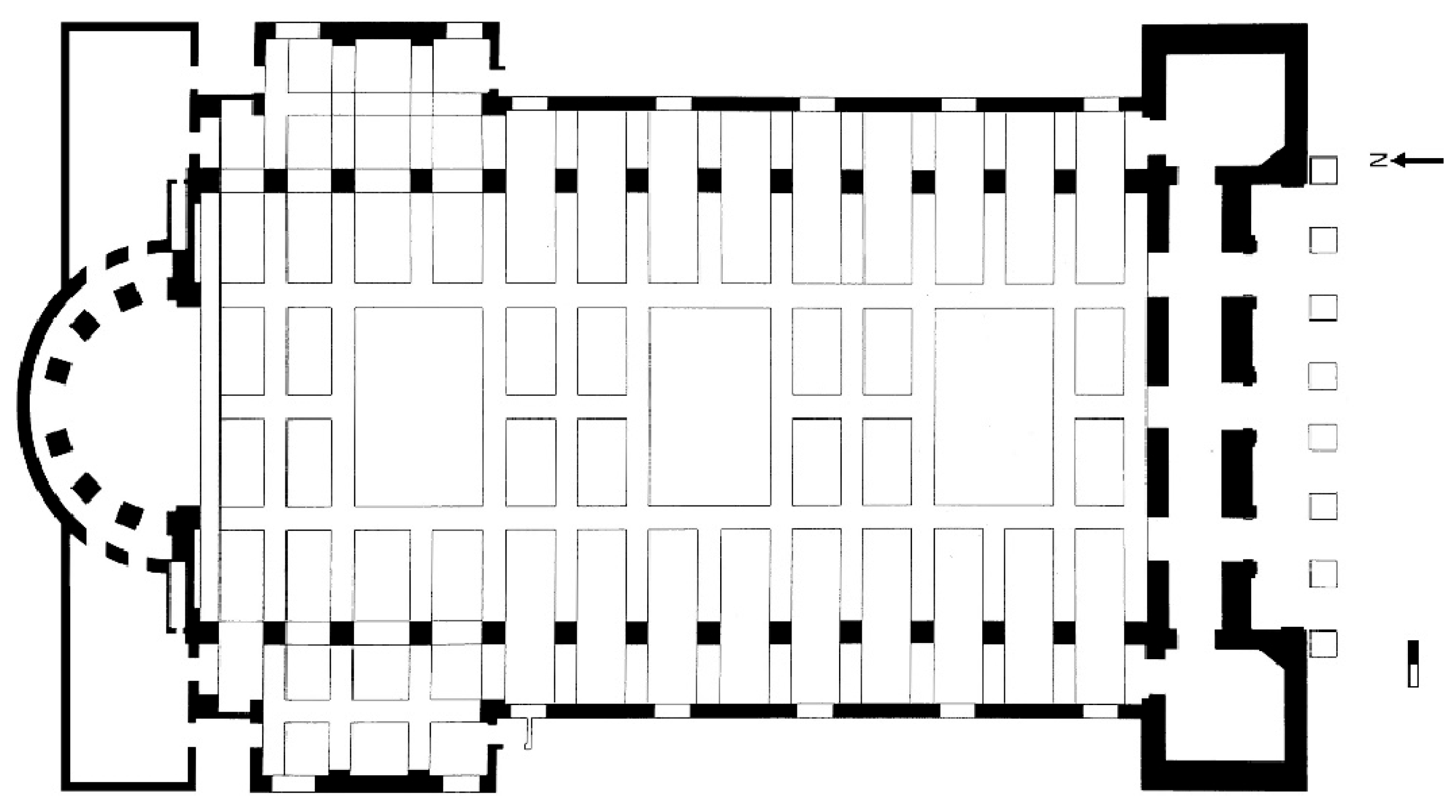
4.1. Historical Description of St Adalbert’s Church in Chicago, the USA

The history of St Adalbert’s church in Chicago is associated with the Catholic parish of the same name, founded in 1874 by Polish immigrants who began to settle in the Czech district of Pilsen, located southwest of downtown Chicago [43]. The construction of the monumental temple designed by Henry J. Schlacks began on 30 June 1912. Construction lasted only two years and on 20 September 1914, the church was consecrated. [44]. The monumental temple’s twin towers measure 185 feet (56 m) and are topped with copper domes (Figure 2). At its peak, the parish had over 4000 Polish families and over 2000 students attended the parish school. From the 1970s, people of Polish origin began to move to other parts of the city, which caused the first difficulties in maintaining the parish buildings and the church.
The interior of the church contains many high-quality decorations and artefacts (Figure 3). The altars, figures, pulpit and balustrades are made of marble imported from Italy. Particularly interesting is the copy of Michelangelo’s Pieta made in Italy in 1914 and the replica of El Greco’s painting of the Assumption of the Blessed Virgin Mary [42]. The stained glass windows were made by the German artist F. X. Zettler (Royal Art Institute in Munich), who also designed them. It should be added that Zettler won first place for his stained glass designs at the World’s Fair in 1893, beating L. C. Tiffany [43]. The interior is covered with polychrome depicting scenes from Polish history: the wedding of the Polish monarchs Jadwiga and Jagiełło and the defense of the Jasna Góra monastery against the Swedes in 1665 (Figure 3). The organ was made by the company W. and W. Kimball [42].
In 2016, the authorities of the Archdiocese of Chicago announced that the church of St Adalbert will be closed due to low attendance at masses and the need for expensive renovations. The last holy mass took place on 14 July 2019, and the parish was joined to the nearby Catholic church of Saint Paul [45]. The Polish community’s efforts to preserve the church have been ongoing since 2016. Despite this, the degradation of the material substance of the church is constantly progressing. On 29 November 2022, a copy of the Pieta was taken to the church of Saint Paul (Mexican community) by dismantling a fragment of the side wall. In the second half of July 2023, the stained glass windows in the side windows were dismantled.

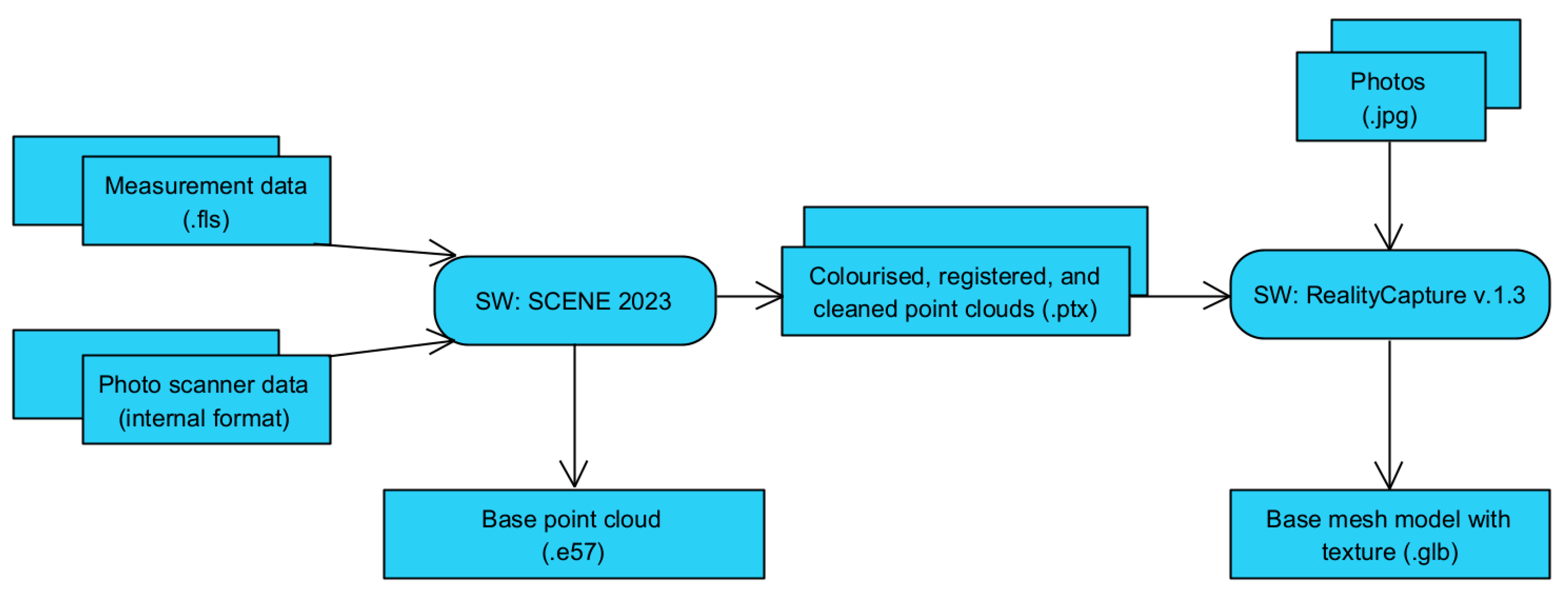
4.2. Digitization Methods and Process

The process of scanning the interior of religious buildings is a complicated issue because we are dealing with a usually extensive and complicated interior in an architectural sense, with very large dimensions of 30 × 70 m, with various elements, such as the main nave, side aisles, transept, presbytery, choir, colonnades, arches, vaults, apses, window and door recesses, or recesses for figures. In addition, there are many elements of equipment in churches: altars understood as offering tables, but also as altar walls very richly decorated, pulpits, confessionals, benches, door and window joinery, stained glass, chandeliers and wall lamps, organs, balustrades, stairs and paintings, sculptures and figures, cornices, pilasters, column capitals and Stations of the Cross, as well as polychromes. The objects inside the church are made of very different materials, such as stone, brick, marble, wood, glass, metals and fabrics, which are characterized by different properties, including very different reactions to the light emitted by the laser scanner (too much absorption, are transparent or are too shiny for them).
Scanning such objects is a very difficult task, especially when it is necessary to fully acquire data on the surfaces of all interior elements, their colors and textures during one stay in such a facility. Such data allow us to build precise digital 3D models of both the interior as a whole and its separate decorative elements and their equipment. For this purpose, the authors used 3D digitization using TLS scanning with a FARO scanner and an enriched series of photographic images. In the case of single sculpture-type objects isolated from the interior of the scanned object (church), they used photogrammetry technology to build a complete digital 3D mesh model along with applying a texture.
The scanning procedure used is presented in Figure 4. It consists of four processes: planning, data acquisition, post-processing and model usage. Appropriate hardware and software tools were selected for its implementation.
In the 3D scanning process, the basic device was the 3D TLS, namely, FARO Premium 150 (made by FARO Technologies, Inc., US). Its factory parameters are presented in Table 1. Photos of the surface were acquired using the built-in camera in the scanner, allowing for the acquisition of omnidirectional panoramas with a resolution of 266 Mpx (Table 1). In parallel, photos were taken using two digital cameras: NIKON D5300 (made by Nikon Co., Tokyo, Japan) with Nikkor 18–140 mm lens and Panasonic DMC-FZ1000 (made by Panasonic Co., Osaka, Japan) with 25–400 mm lens (Figure 4).
The FARO Premium 150 scanner used was calibrated to determine the actual measurement error parameters. The basic calibration results are presented in Table 2. As can be seen, the real measurement quality parameters of the scanner used are much better than the factory ones.
The authors’ experience gained during scientific expeditions to central Asian countries, including Uzbekistan, where the interior of the Juma Mosque (Khiva) [1] or the Golden Mosque of the Tillya-Kori Madrasah (Registan, Samarkand) [8] and many other architectural structures from the Timuridian era were scanned [11,16,25], resulted in the belief that creating photographic documentation of scanned objects is a very important part of acquiring data on the appearance of objects, because it allows for the use of a hybrid approach in the preparation of full 3D digital models. Thus, when creating photographic documentation of the interior of a large architectural building, the authors take photos that can be classified into one of the following three groups:
  • General Plan Photos (GPP)—photographs showing 0.4–0.8 of the area of the entire facility. They enable easy assembly of photos using the photogrammetry method. Photography is taken at a focal length of 15 to 30 mm.
  • Medium Plan Photos (MPP)—photos containing a fragment of an object. These photographs are taken from a sufficiently close distance and at a sufficiently high resolution to enable the correct reconstruction of the shape and appearance of the object with the required level of detail. These photos are positioned (registered) based on an already existing rough 3D digital models built from GPP. Photographing is performed at a focal length of 30 to 50 mm.
  • Detailed Photos (DP)—photos containing individual details. They enable the transfer of good and very good quality textures to 3D digital models. Photographing is performed at a focal length of 70 to 200 mm.
This scheme for photographing the interior of the church of St. Adalbert was used during data acquisition and post-processing.
The post-processing aims to combine many point clouds into one according to their registration and colorization, as well as to clean them from interference into one base cloud (Figure 5). Unfortunately, the latter activity is performed manually. This is the most labor-intensive part of post-processing. A base mesh model with texture is generated from the processed point clouds.
The specifics of the devices for processing the acquired data and the software used are presented in Table 3. The expedition had a laptop with significant computing power which was used to carry out initial processing to check the correctness of the collected data.
The processing of the acquired point clouds is carried out using the FARO SCENE 2023 software in the following stages:
  • Cloud downloading (with conversion of the spherical coordinate system to Cartesian);
  • Coloring the cloud points based on photos taken by the scanner;
  • Cloud registration (including conversion of the coordinates of points of various clouds to one coordinate system);
  • Cleaning the point clouds of unnecessary objects (e.g., people) and incorrect coloring;
  • Exporting cleaned clouds of individual scans;
  • Creating a base cloud by combining the clouds into one.
The process of creating a base mesh model with texture is carried out using RealityCapture 1.3 software. This process is based on a set of cleaned colored point clouds for geometry reconstruction. A texture consistent with the colors of the base cloud is applied to the generated mesh model. During its generation, it can use photos taken with digital cameras (Figure 5). This increases the accuracy of color reproduction in the texture.
The following universal data formats are used to save post-processing results (Figure 5):
  • e57—an independent, extensible industry standard for recording 3D imaging data developed by the American Society for Testing and Materials and specified in ASTM E2807 [46];
  • ptx—an ASCII-based format for saving point cloud data, typically from LIDAR scanners, used as intermediate data transfer between Scene and RealityCapture;
  • glb—a standardized file format used to share 3D data, with all assets (3D mesh and textures) stored in a one binary file.
The base models provide the basis for further transformations and creation as needed (Figure 4): simplified mesh models with texture, panoramas, movies, digital reconstructions and VR files.

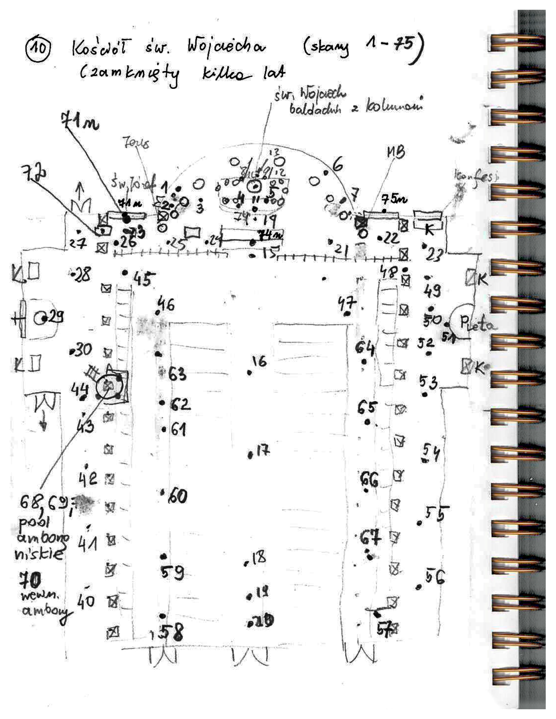
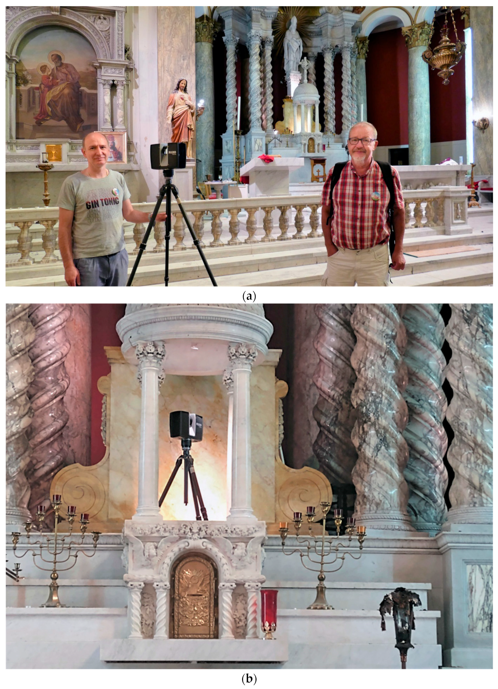
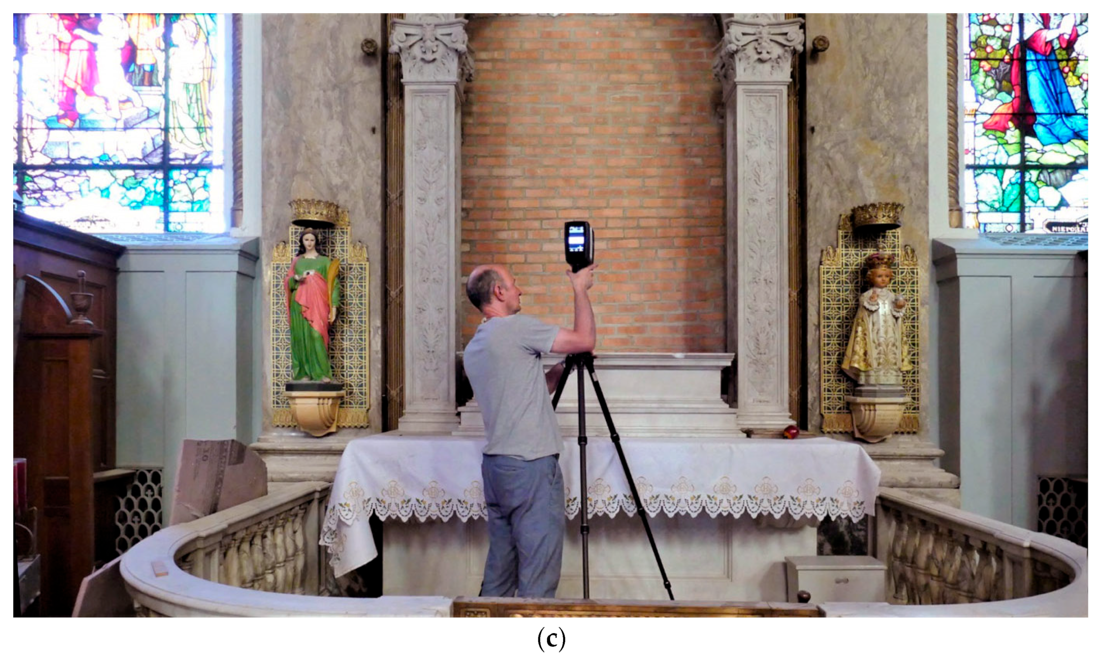
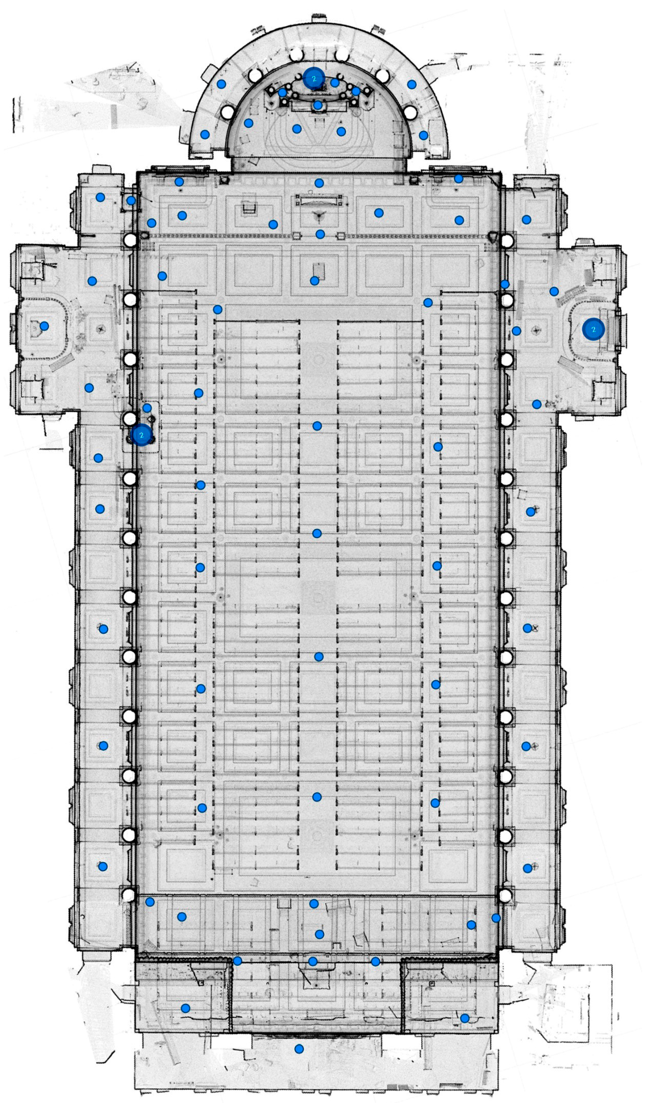
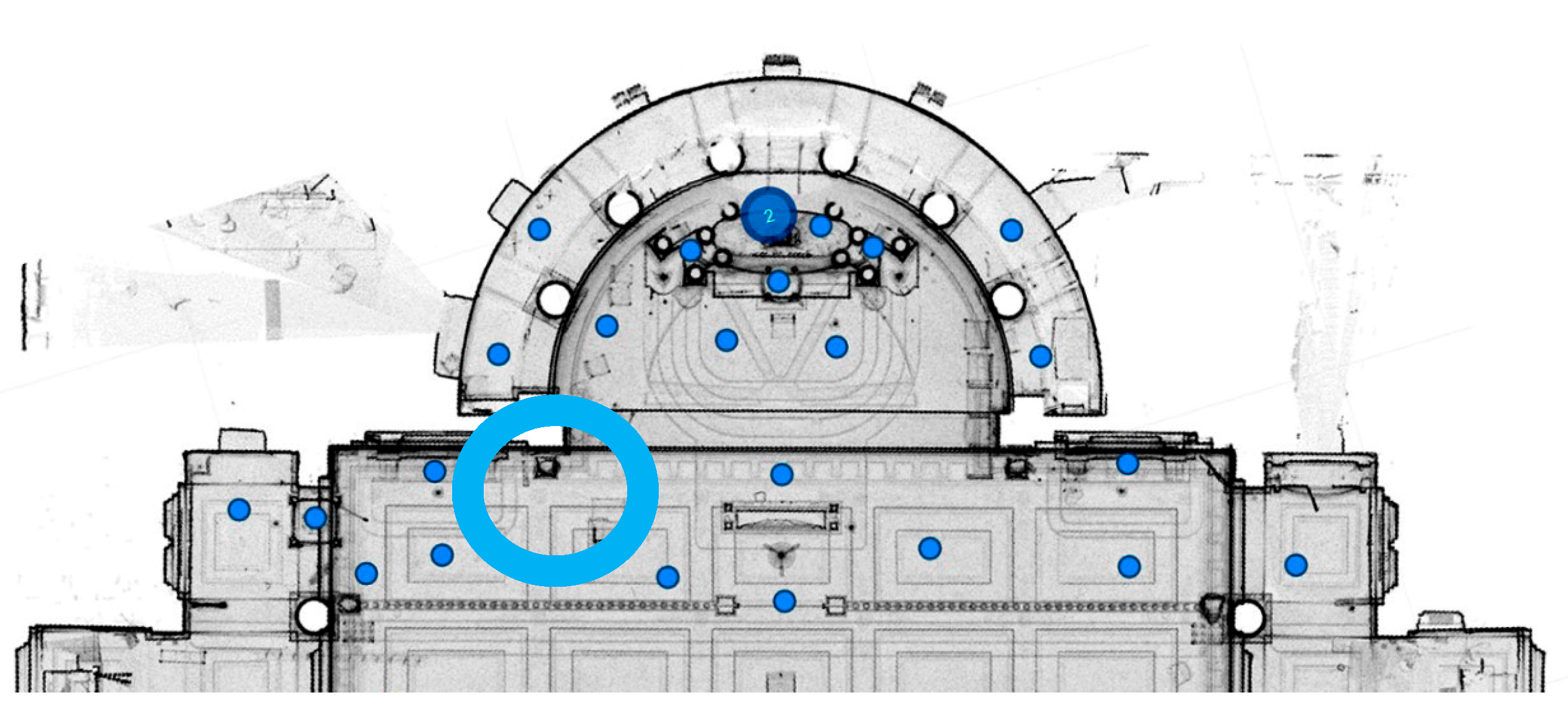
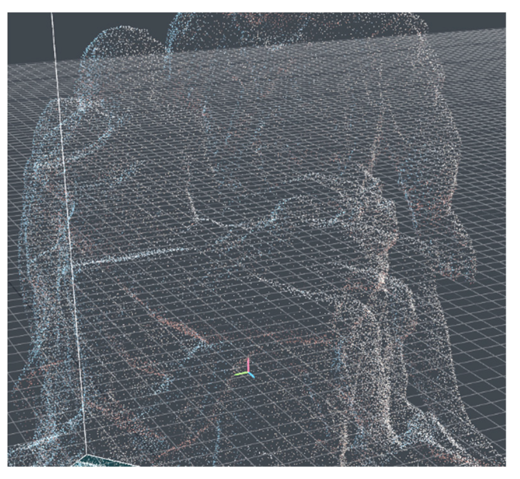
4.3. 3D Scanning of St Adalbert’s Church Interior

The team was given access to St Adalbert’s church in Chicago (closed for four years) for one working day (8 h) from 8 a.m. to 4 p.m. The internal dimensions of the building are as follows: 190 feet (57.5 m) long, 113 feet wide (34 m) and 110 feet (33 m) high (the vault) (Figure 6). The church has three levels (i.e., nave, choir and organ).
The team’s first action was to estimate the number of scans needed on all three levels of the church. This number was initially estimated at 75.
In accordance with the used methodology (Figure 4), the following parameters of the 3D scanning process using the FARO Premium 150 scanner were estimated:
  • Facility availability time: 8 h (one working day).
  • Number of scans (preliminarily planned in situ): 75.
  • Calculated estimated time for one scan (including manual activities)—scanning time budget: 6:24 min.
On this basis, the parameters of the scanning process were determined:
  • Scanning parameters by FARO: 1/2; ×2; 360/300 (Table 4), which gives the time to complete one scan as 5:13 min.
  • Planned scan time: 6:32 h.
  • Time reserved for manual activities and possible repetitions: 1:28 h.
As a result of estimating the parameters of 3D scanning of the church interior, the scanning parameters using the FARO Premium 150 scanner (made by FARO Technologies, Inc., US) were determined and are presented in Table 4.
Then, a manual sketch of the church plan was made (Figure 7). This sketch was used to record the scan points (points with numbers in Figure 7) and their parameters (e.g., low or high position of the scanner) on an ongoing basis. As a result, 74 scans were performed on all three levels of the church rooms.
Due to the fact that a former church building was scanned, it was possible to use any scanner settings, including in places inaccessible when scanning a functioning church (Figure 8).

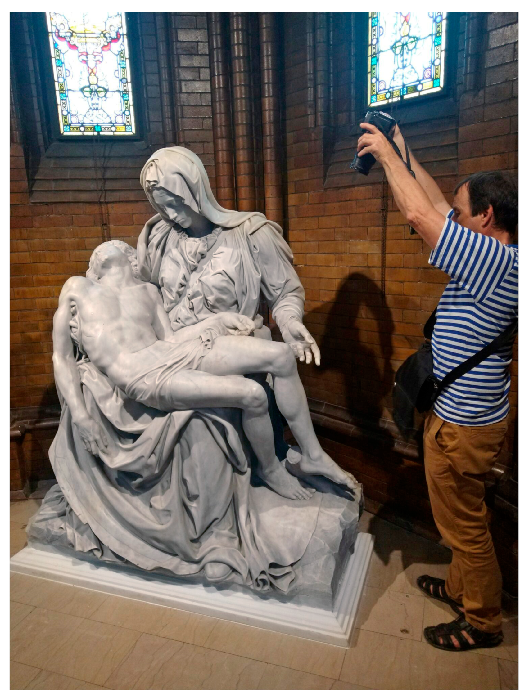
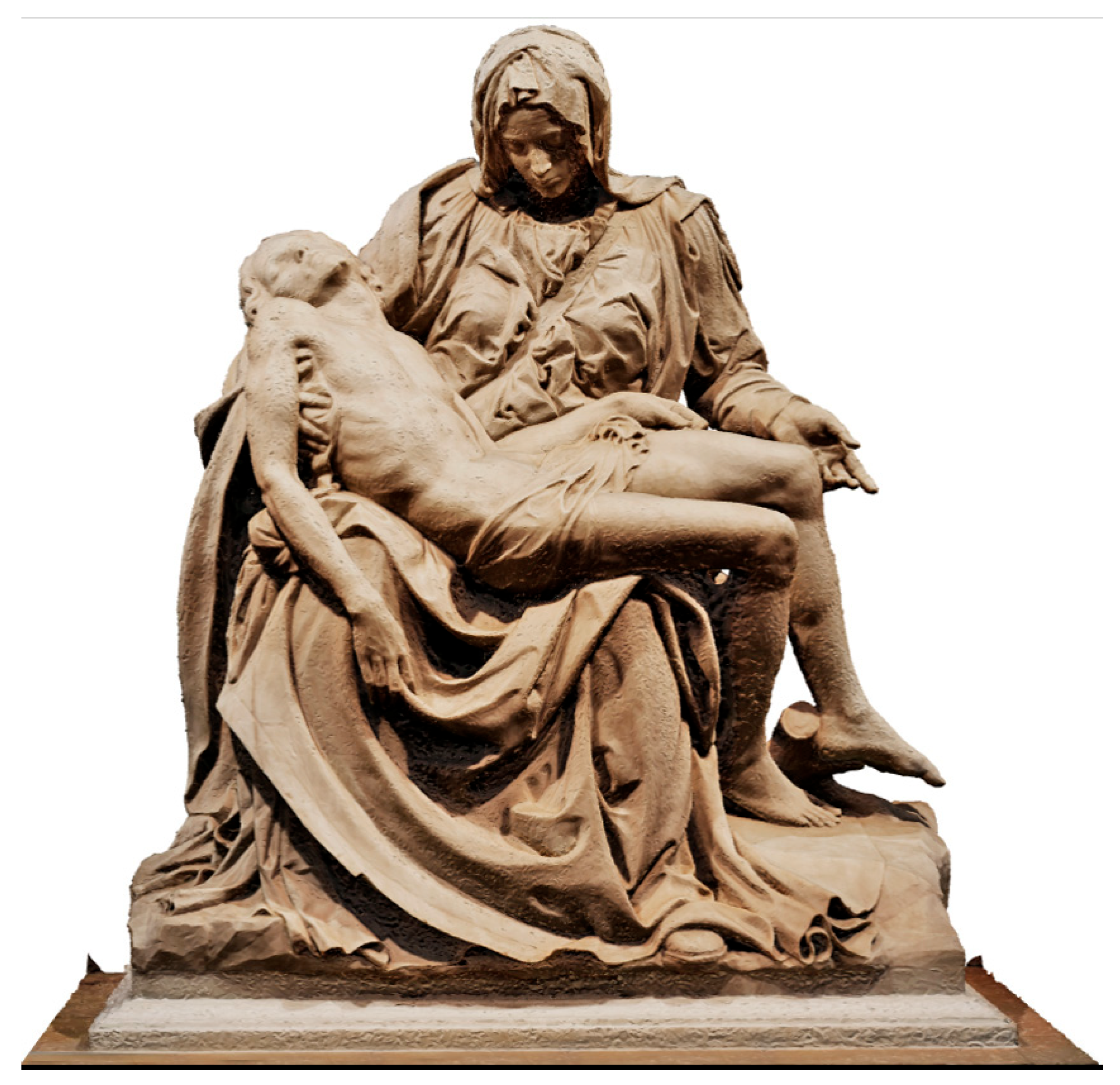
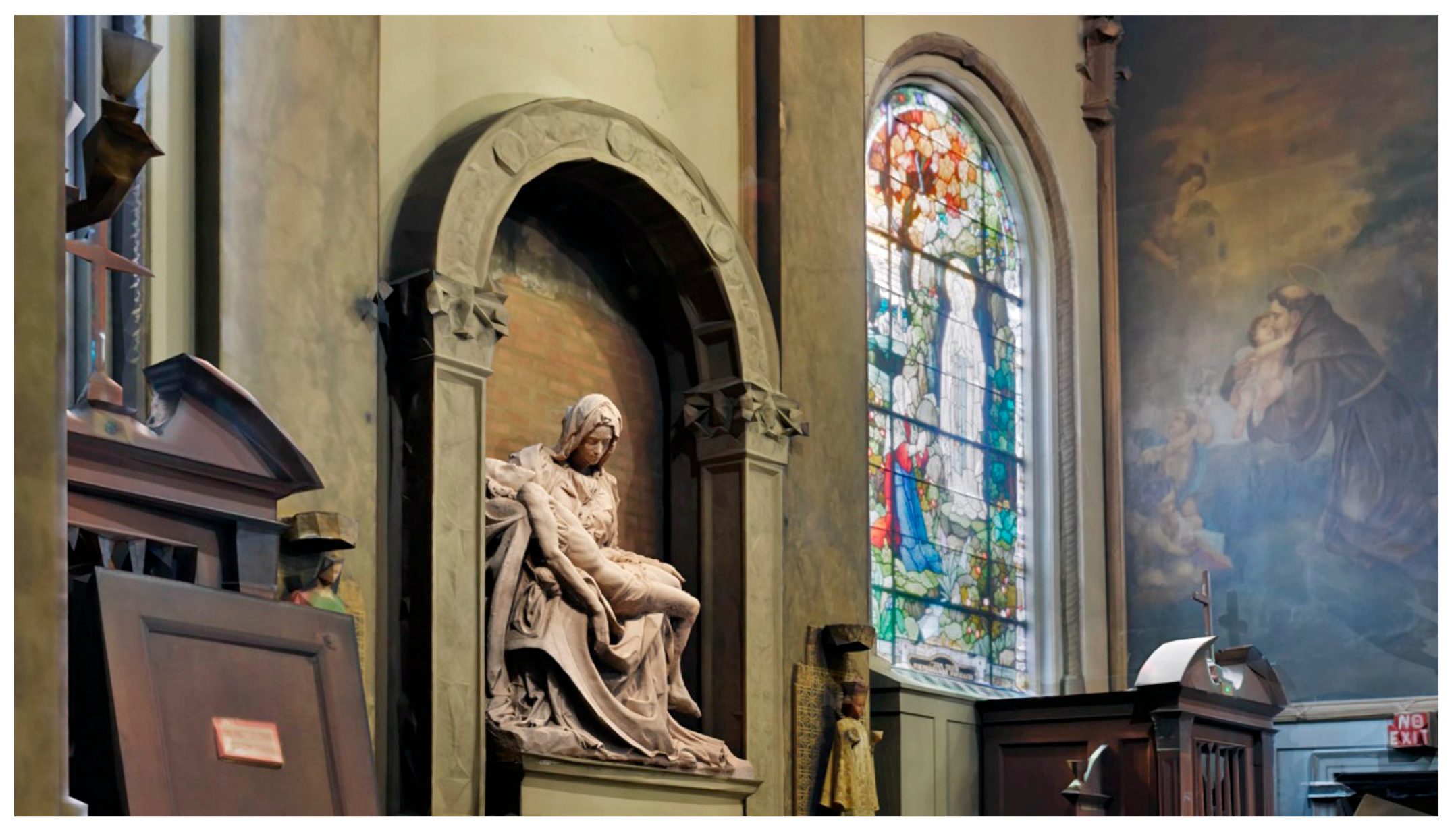
4.4. Photogrammetric Data Acquisition of the Pieta Sculpture

The Pieta is a faithful copy of a renaissance sculpture by Michelangelo located in the Vatican’s St Peter’s Basilica made in Italy in 1914. On 29 November 2022, it was moved to the church of St Paul in Chicago. During the scientific expedition, permission was obtained to take a number of photos in order to create a 3D model of the Pieta using the photogrammetry method (Figure 9).

5. Results

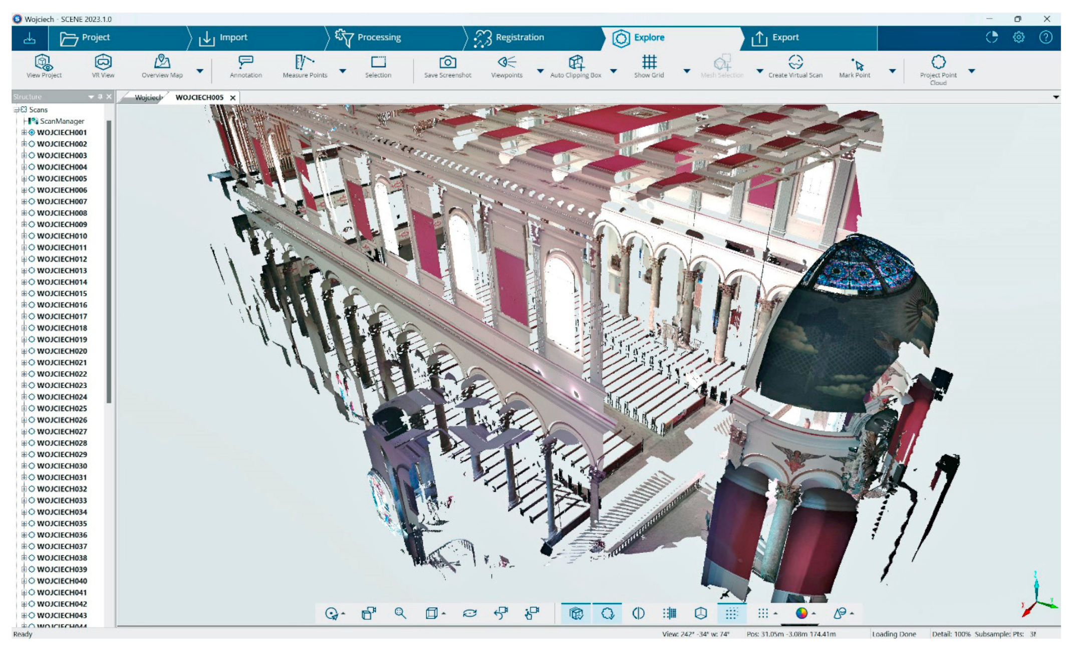
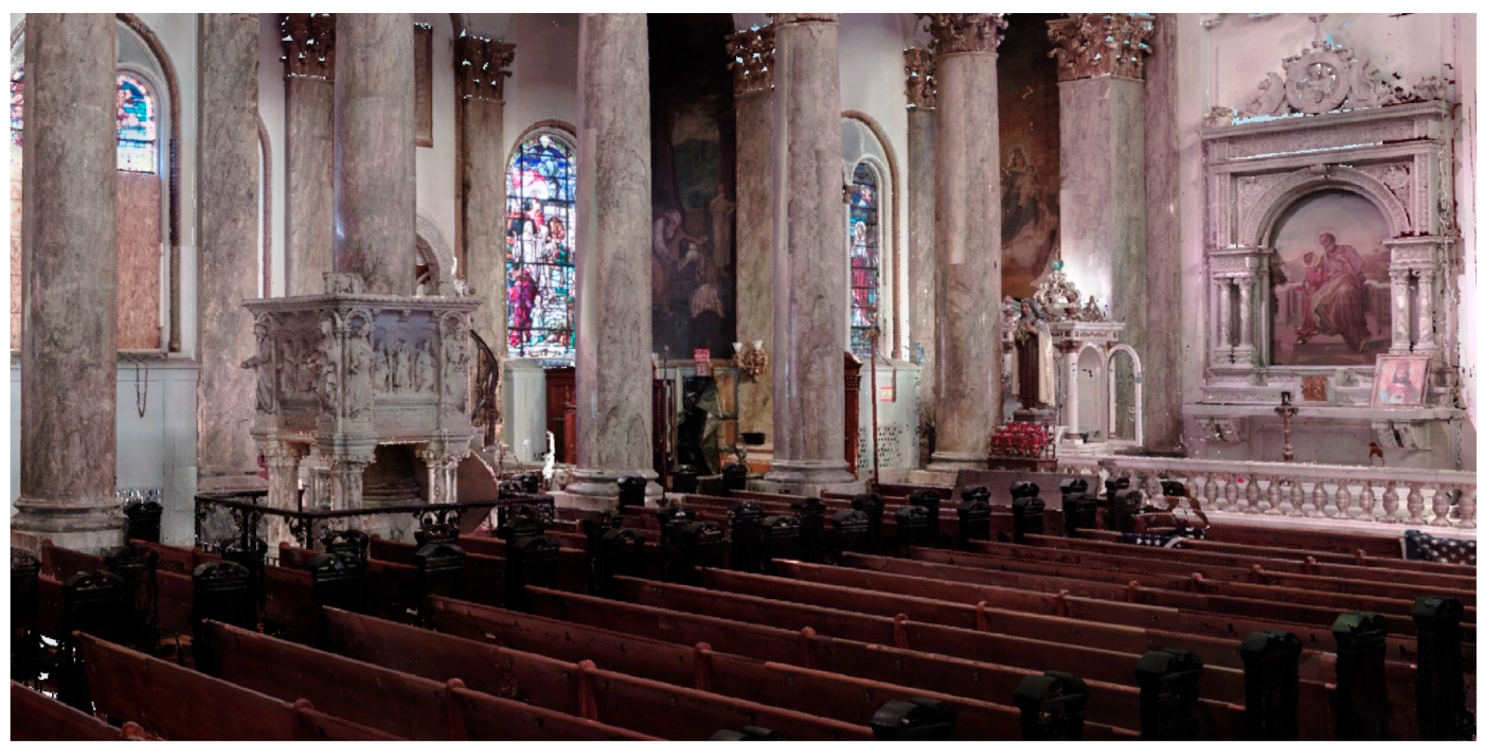
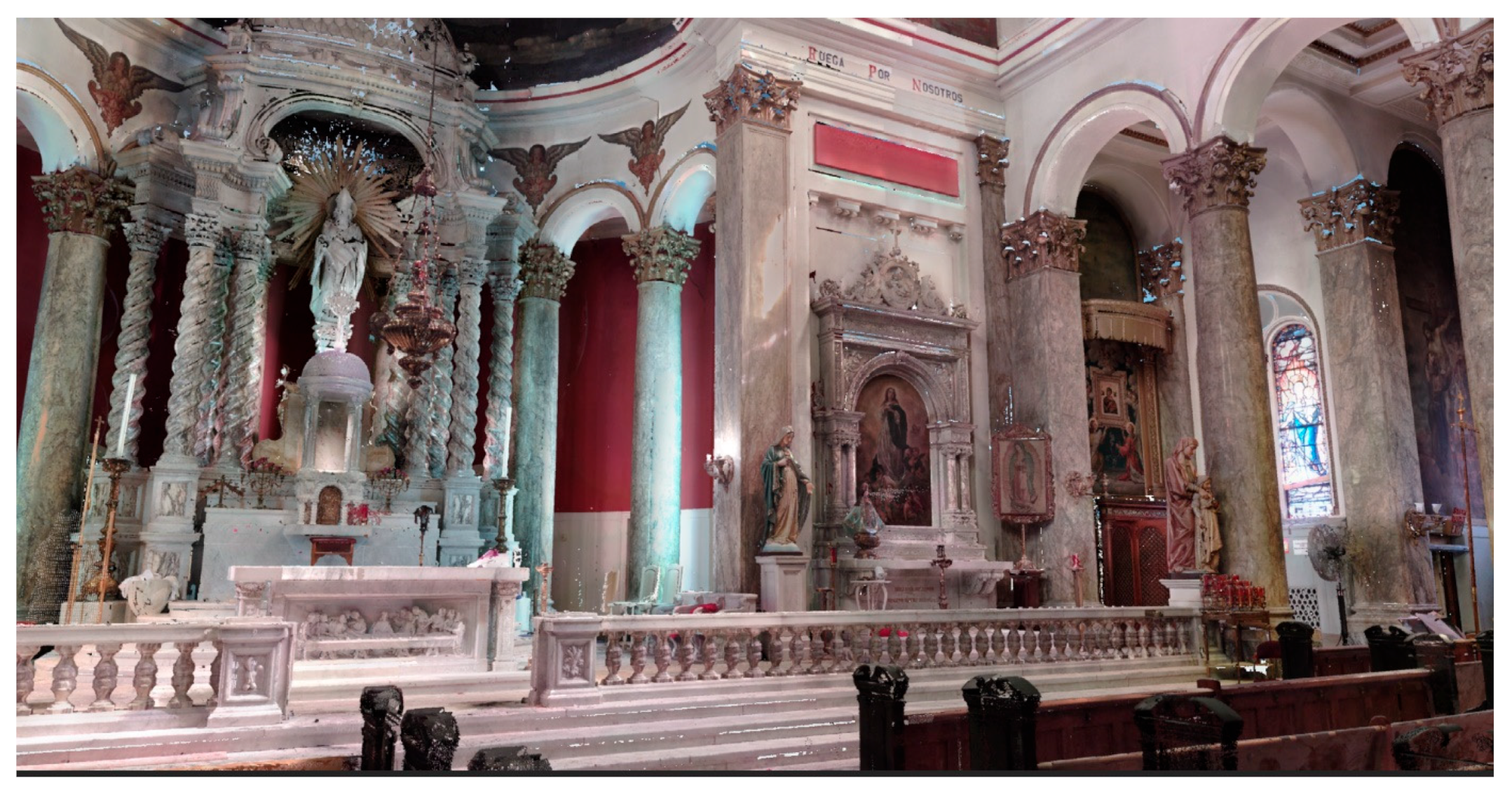
5.1. Results of 3D Scanning of the Church Interior

Parameters of the data obtained during the intervention scanning (3D and photo) of the interior of the building of the former church of St Adalbert in Chicago are presented in Table 5 and Table 6. This is how much was obtained within 8 h of the facility’s availability.
Actual positions of the scanner while scanning the first level of St Adalbert’s church building in Chicago are shown in Figure 10.
The base point cloud in SCENE 2023 is shown in Figure 11, and the base mesh model in RealityCapture 1.3 is shown in Figure 12. Figure 12 shows a view of the textured model, simplified to the maximum size that can be displayed in mesh mode by the equipment available at the time of the project. Modern, publicly available graphics cards are not able to process and display 3D meshes which are the size of the base mesh model generated in RealityCapture 1.3 (only a preview in point cloud mode is available).

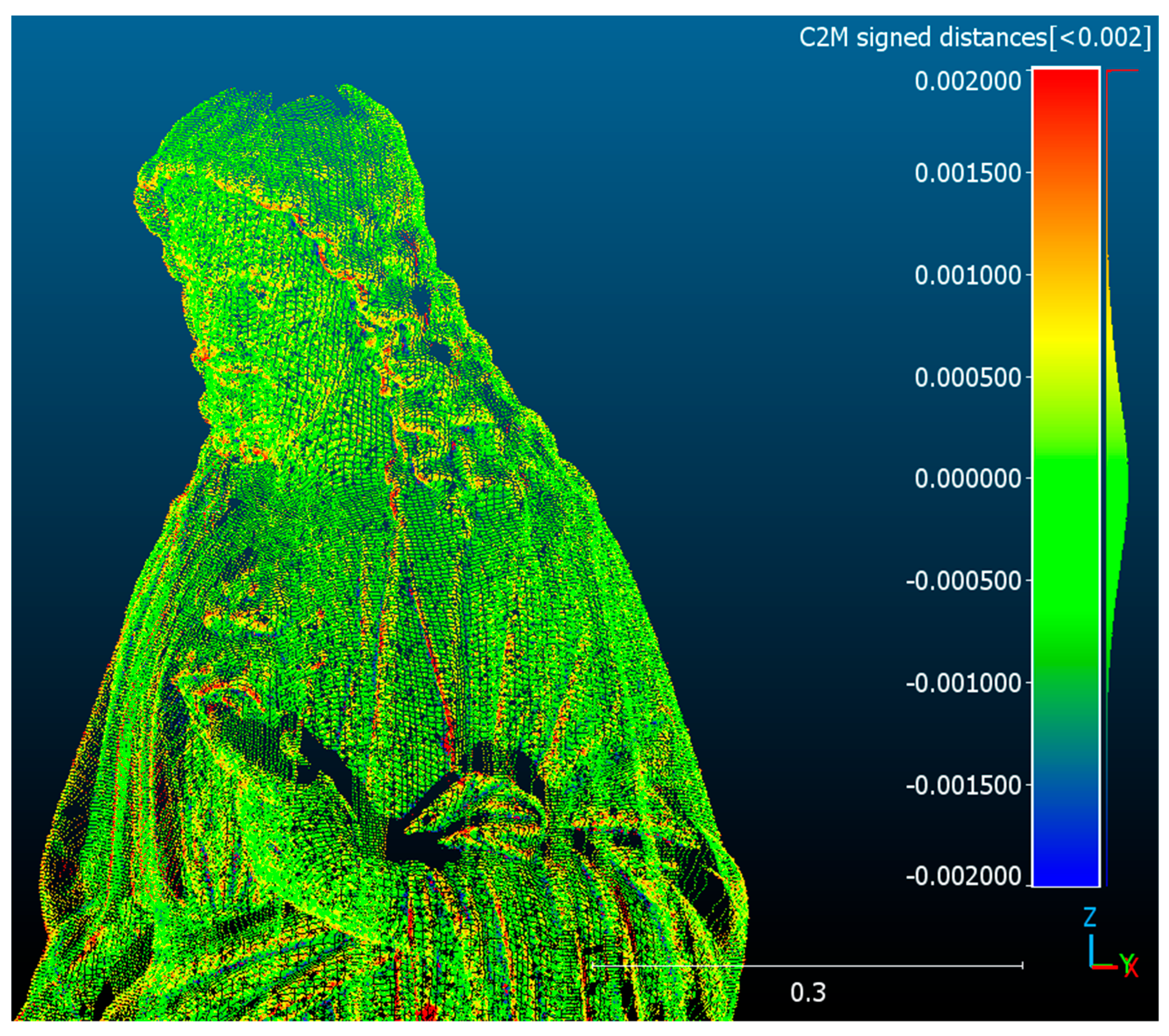
5.2. Assessment of the Accuracy of the Results of Scanning and Modeling the Interior of the Church Building of St Adalbert in Chicago

In order to determine the accuracy of scanning and modeling the interior of the church building of St Adalbert in Chicago, a mesh model of the figure of Christ, which is an element of the interior near the altar (Figure 8a and Figure 13), was made. The figure is located in the visibility of many (about 10) scans taken from a distance of less than 10 m. The point cloud was extracted from the base point cloud using the SCENE 2023 program. The 3D mesh model of the figure was created in RealityCapture 1.3 software using the most faithful point cloud reproduction option. The result is shown in Figure 14 and the model parameters in Table 7.
The enlarged fragment of the 3D model from Figure 14 shown in Figure 15 presents the accuracy of mapping the geometric parameters of the surface of the church interior elements obtained as a result of scanning. The sides of the triangles forming the mesh model in Figure 15 are approximately 2–3 mm long. The analysis of the accuracy of the reproduction of this figure allows us to confirm that the model reproduced the interior with high accuracy.
Using the CloudCompare v2.12.4 software, a comparison was made for the figure of Christ between the measurement cloud (points) and its generated 3D mesh model. The result of comparing the distances between the points of the cloud and the mesh model is shown in Figure 16 as a C2M (cloud-to-mesh) signed distance. The results of the numerical assessment of the quality of the generated models based on the comparison data of the point cloud and the mesh model for absolute distances (unsigned) are shown in Table 8.
The standard deviation ( s ) of absolute mismatch models (Table 8) was determined using the following formula:
s = i = 1 n ( x i x ¯ ) 2 n ,
where:
x i —absolute value of the difference between the point cloud and the mesh model;
x ¯ —average value of absolute differences between the point cloud and the mesh model;
n —number of cloud mesh model distance measurements.
The point cloud obtained using the FARO Premium 150 scanner can be considered an etalon with the accuracy of the scanner calibration, i.e., with a systematic scanning error of no more than 0.36 mm for a distance of up to 25 m (Table 2). Processing the point cloud into a mesh model has a method error of 0.335 mm (Table 7). The total error ( δ ) of the 3D model of the figure of Christ can therefore be determined as follows:
δ = δ s c 2 + δ p p 2 ,
where:
δ s c 2 —systematic scanner error;
δ p p 2 —error of the method, i.e., creating a mesh model from a point cloud.
For the figure of Christ, the total error of the model is 0.492 mm. This error can be transferred to other internal structures of the church.

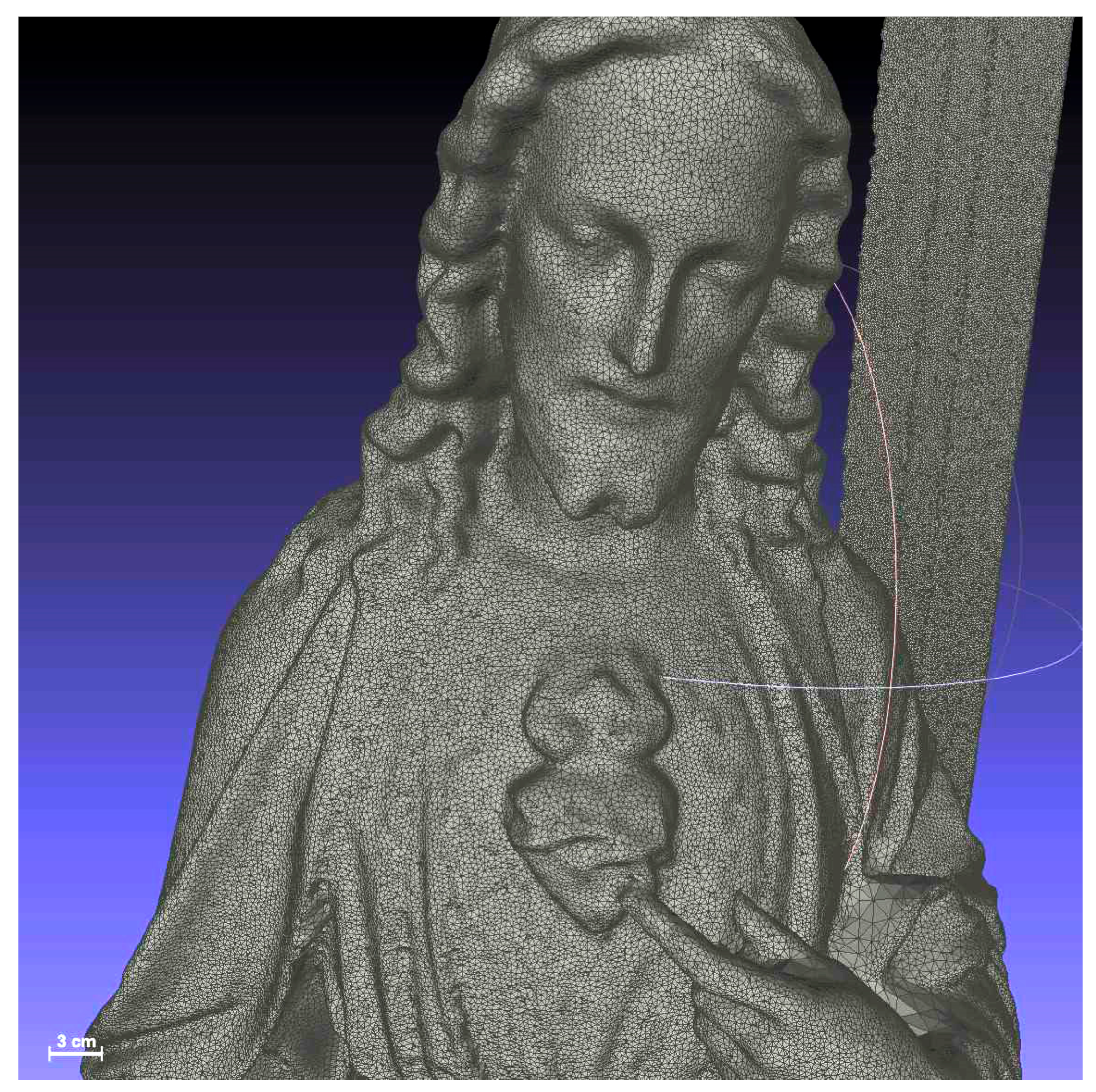
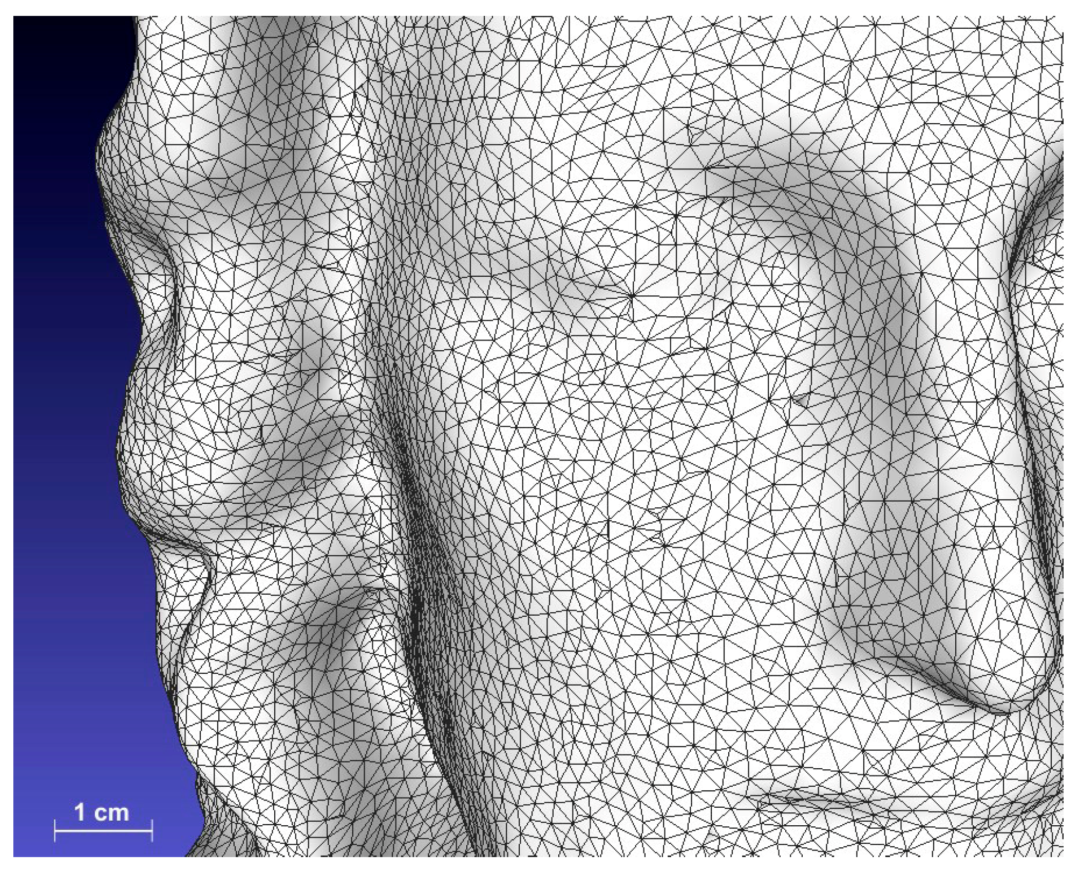
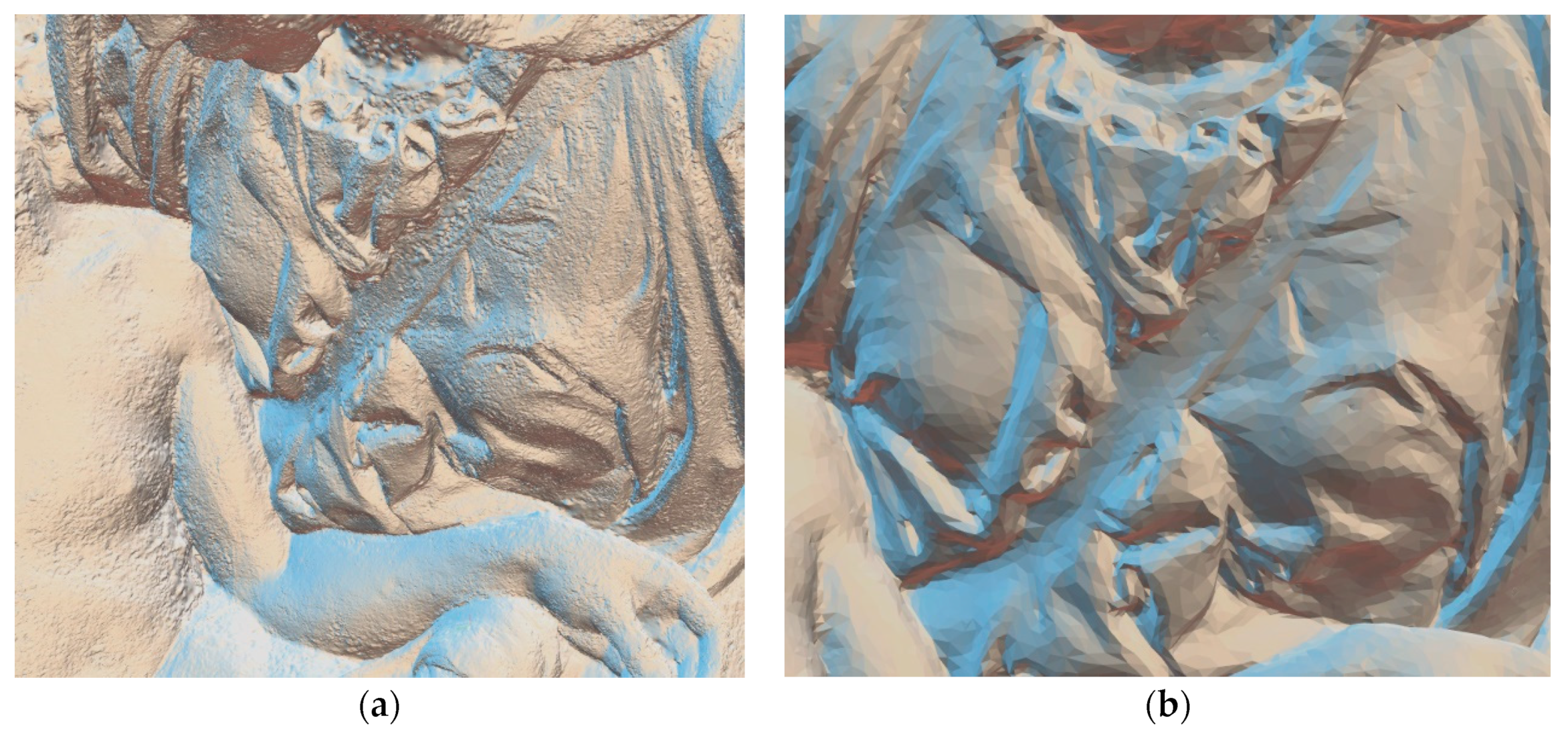
5.3. The Results of Photographing the Pieta Sculpture

During the shooting, 569 photos were taken using two cameras: NIKON D5300 (made by Nikon Co., Japan)—426 photos (27 GPP and 399 DP) and Panasonic DMC-FZ1000 (made by Panasonic Co., Japan)—143 photos (14 GPP and 129 DP). Due to the fact that the sculpture stood directly on the floor, access to it was significantly easier, but it was located a short distance from the wall, which made photographing the back of the sculpture difficult.
Using professional RealityCapture 1.3 software, a digital 3D model of the Pieta was created based on photos in the following stages:
Stage 1—generating a 3D cloud model (Figure 17). The program registered 382 photos, and the process lasted 3.5 min. A detailed analysis of the rejected photos showed that many of them were out of focus, especially those taken at arm’s length when the back of the sculpture was photographed.
Stage 2—generating a base 3D mesh model. The model complexity was nearly 55 million triangles (Figure 18a) and the completion time was 6.4 min. Such a large model was not suitable for widespread use, and its surface was too rough.
Stage 3—simplifying and smoothing to generate a 3D model for distribution. The complexity of the 3D model was 300 thousand triangles and the completion time was 7 min (Figure 18b).
Stage 4—texturing to generate a 3D model for dissemination and mapping using two textures with resolutions of 8192 × 8192 px (Figure 19). A 50 MB model was obtained and is available on the website: polishheritage3d.eu (accessed on 10 January 2024).

5.4. Post-Processing Results

The acquired data clouds were subjected to post-processing in accordance with Figure 5. Due to the huge amounts of information (e.g., the number of points in the base point cloud was 3,500,000,000, and the size of the file in the e57 format was 65 GB), post-processing was carried out on a high-end computing workstation, with a processor with 64 cores and RAM of 512 GB (Table 3). The time taken to create the base cloud (Figure 20) in the SCENE program on this computer was over 3.5 h. Very similarly, it took almost 3 h to generate a 3D mesh model with texture (Figure 21) using RealityCapture 1.3 (Table 5). Its volume was 60 GB. The underlying models (cloud and mesh) were used for different purposes.

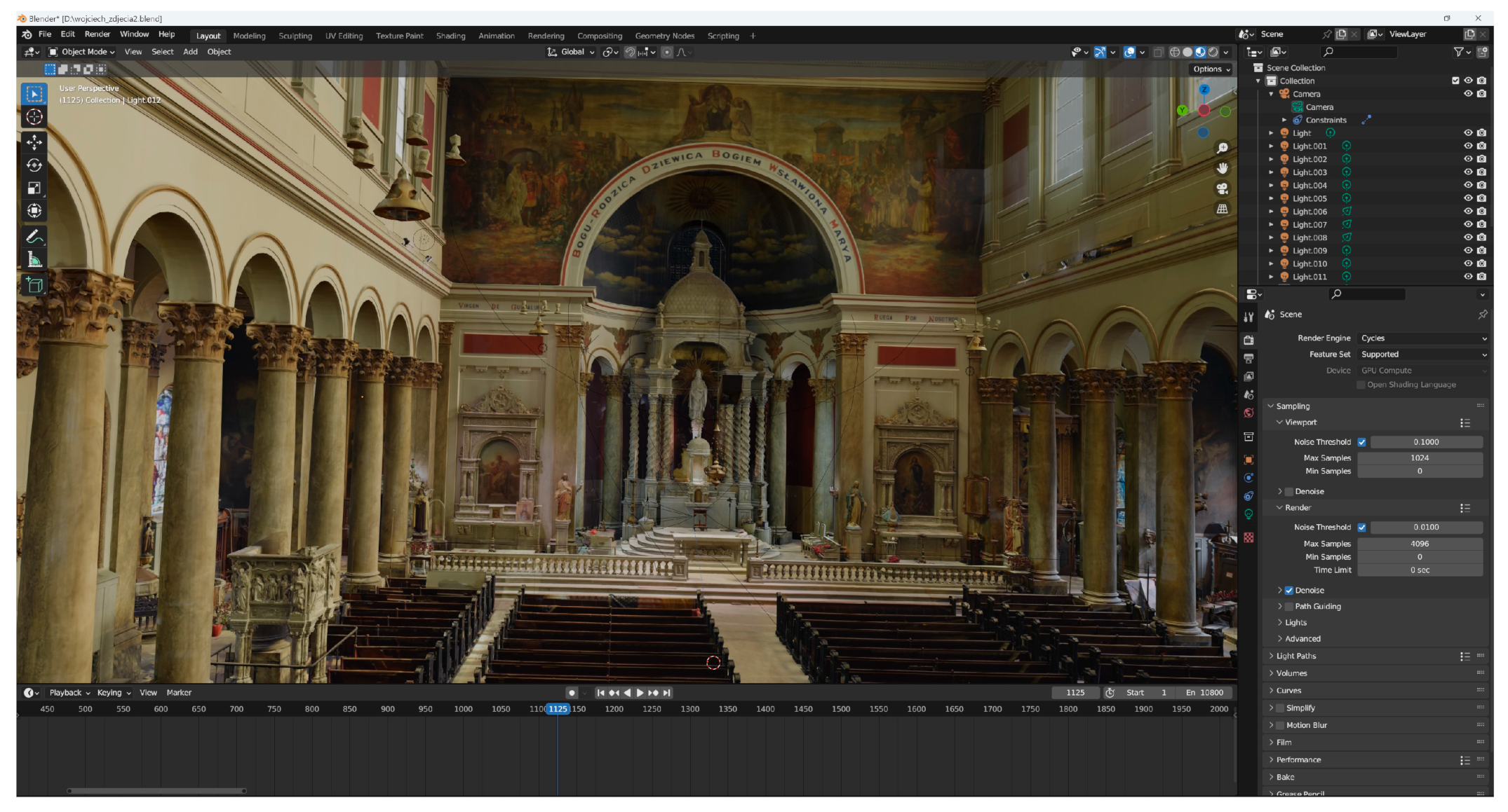
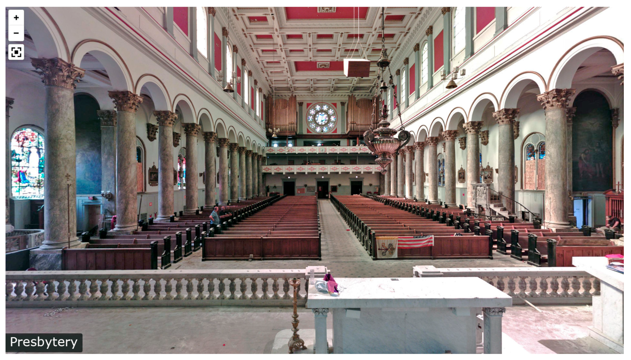
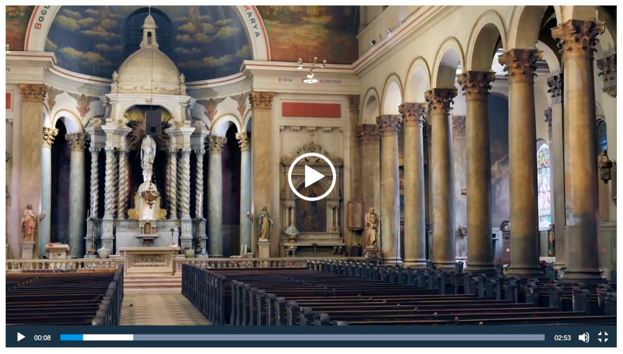
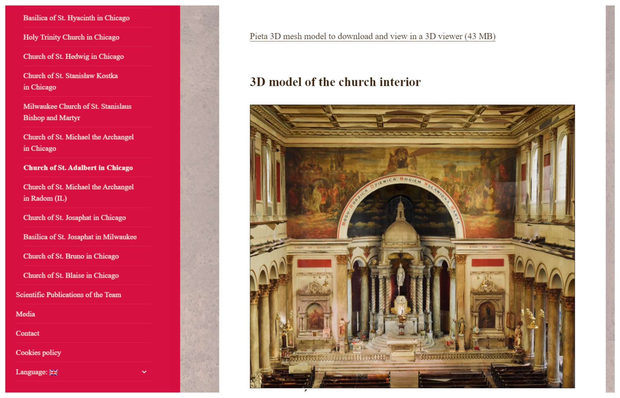
5.5. Using a 3D Model of the Church Interior

Due to their volume (60 GB and 65 GB), the base models are very difficult to use directly, e.g., for research purposes or for dissemination. They constitute a perpetual archive of the appearance and dimensions of the church of St. Adalbert’s interior in its condition at the time of scanning. These models are available in open access science resources. To use them practically, they can be processed for various purposes:
  • Generating 3D panoramas from various points inside the church (Figure 22). Panoramas are created in SCENE 2013 (you can also use Blender 4.0 for these purposes).
  • Creating high-quality videos of “flights” inside the church (Figure 23). The videos are created using Blender 4.0 using a base point cloud. Unfortunately, this process is very long: generating a 3 min video on the workstation (with parameters as in Table 3) took 78 h.
  • Making the 3D mesh model of the church interior available online for viewing in web browsers and locally (Figure 24). Such models cannot be too large (max. 400 MB), so it is necessary to simplify the base mesh model using the RealityCapture 1.3 program.
  • Digital reconstruction of lost interior elements [47]. Using the Blender 4.0 program, with a mesh model of the Pieta’s interior and sculpture, the Pieta was digitally “inserted” into its historical place (Figure 25).
All of the above-presented forms of dissemination of the results of documentation work using 3D technology of the interior of the church of St Adalbert in Chicago were published on the website polishheritage3d.eu (accessed on 10 January 2024) or polskiedziedzictwo3d.pl (accessed on 10 January 2024).

6. Discussion

Obtaining a digital 3D model of the church interior with all of the decorative details and its furnishings in the process of emergency 3D scanning was a unique undertaking, especially since, at the same time, part of the team went in search of the Pieta sculpture removed from the interior of the church in order to take a series of photos of it for modelling using photogrammetry technology. Although the work took almost 8 h, it was a complete success. For example, the authors in a similar work [48] devoted as many as 6 days to acquiring data in similar conditions.
The obtained quality of modeling the interior and furnishings of the church using TLS turned out to be extremely good, which contradicts the reports published in [8]. In this work, the digital 3D model of the Holy Christ of the Blood sculpture obtained using TLS technology was of significantly lower quality than models obtained using SLS technology and photogrammetry and was basically unsuitable for presentation, let alone sharing. Also, the quality of the interior elements in the work of [48], e.g., Mihrab, was not good. Obtaining significantly better quality models may result from progress in the accuracy of TLS devices as well as differences in the number and arrangement of scanning positions.
The use of a hybrid approach to generating a digital 3D model of the church interior with the characteristics of a realistic model, in which the generation of the model geometry was based on TLS data and TSRP photos were used to generate a high-resolution texture, turned out to be the right solution, which is confirmed by the results obtained in this work. So far, the method of combining photos with 3D models has been successfully used to create models of architectural objects [13,49], but there is no information on it concerning building interiors.
Progress in the field of computational efficiency of modern computers is a very important issue from the point of view of 3D digitization of cultural heritage objects. Currently, equipment with high-performance parameters allows us, in a reasonable time, to obtain models of significantly higher quality than was previously possible, e.g., in [48], where the calculations took many days and it was not feasible to select optimal process parameters.
Due to the interventional nature of the task of scanning the interior of the church, the scanning parameters had to be adapted to the existing realities. Both negative and positive factors had to be taken into account.
The negative factors in this study were as follows:
  • The need to perform the scan once and in existing conditions.
  • Limited scanning task execution time.
  • Predefined scanning date—suboptimal lighting conditions.
  • Cannot repeat scanning.
The positive factors in this study were as follows:
  • Exclusive access to the interior of the facility—no outsiders disturbing the scanning process.
  • Desacralization of the object—the ability to place the scanner in any technically accessible place.
Table 9 shows the influence of the specified factors on the scanning parameters.

7. Conclusions

This work presents a method for scanning a complex church interior using a TLS scanner and documenting the view of its interior using cameras and the TSRP method. Moreover, using the TSRP method, a series of photos of the found Pieta sculpture were taken and a digital 3D model was generated, which could virtually be placed in its former place in the digital model of the interior of St Adalbert’s Church in Chicago.
The obtained results allow for the following conclusions to be formulated:
  • Data acquisition using the TLS method, using appropriate process parameters, allows for effective 3D intervention scanning of the interior of a large historic building (such as a church) with a very complicated architectural structure and numerous interior furnishings with various types of details.
  • The key issue during this work was the selection of digitization parameters so that a significant number of scans could be performed in the available time. For the example in question, with the size of the church interior of 30 × 50 × 30 m in 8 h, over six dozen scans were performed. This was possible by establishing such scanner operation settings that limited immunity to interference (occurring to a small extent in a closed facility) while maintaining the highest possible resolution of a single scan, minimizing its execution time to the available limit of 6:24 min per scan. It should also be remembered that it is crucial to properly calibrate the scanner so that the data obtained are of appropriate quality.
  • Three-dimensional digital mesh models of individual pieces of equipment are sufficiently detailed, as can be seen from the example of the Christ sculpture shown.
  • It is a good practice to take a series of photos to generate digital 3D models using photogrammetry; if possible, the photos should be taken by two different people using two different cameras. Details accidentally omitted in one set are most often available in the second set. The model and texture generation software can operate on significant sets of images (thousands) without slowing down processing time too much.
  • The RealityCapture program, using a computer with very high computing capabilities, has become a very effective software that allows for multiple recalculations of point clouds and testing various variants of actions at the post-processing stage.
  • Even though Blender is a free software, it turned out to be very useful at the stage of digitally assembling the Pieta sculpture at the altar niche from which it was physically taken. Moreover, it has become a very effective tool for generating a movie presenting a virtual camera’s flight inside the created digital 3D model of the church.
  • Having access to high-power computing units is an essential element of efficient post-pressing activities. For example, the above-mentioned movie with a broadcast time of 180 s (3 min) at 24 frames per second was generated for over 78 h.
The developed base model of the church interior (both in the form of a colored point cloud and a textured mesh) has already been used to generate many models for dissemination (panoramas, film and reconstruction; see https://polishheritage3d.eu/projekt-usa/kosciol-sw-wojciecha-w-chicago/ (accessed on 10 January 2024)). In the future, it is planned to create models for VR and the metaverse. In addition, the model will be permanently stored and made available to other researchers—historians, art historians, theologians, etc.

Author Contributions

Conceptualization, M.M. and J.M.; methodology, M.M. and J.M.; validation, M.M. and J.K.; formal analysis, M.M. and J.K.; investigation, M.M. and J.M.; resources, M.M.; data curation, J.K.; writing—original draft preparation, M.M., J.M. and J.K.; writing—review and editing, M.M. and J.K.; visualization, M.M. and J.K.; supervision, M.M.; project administration, M.M.; funding acquisition, M.M. All authors have read and agreed to the published version of the manuscript.

Funding

This research was financed by the Polish Minister of Education and Science by the project “Research on the national cultural heritage of the Polish community in the US and the creation of digital memory collections” (grant no.: NdS/545613/2022/2022) as a part of the “Science for Society” program in the area “Humanities-Society-Identity”. The APC was funded by MDPI.

Data Availability Statement

Data created during this project in a dissemination format are available on the website polishheritage3d.com (accessed on 10 January 2024). Base models, due to their very large size, will be made available by the ECCC Foundation after a justified request.

Acknowledgments

We would like to thank the Polish community in Chicago for making the research possible.

Conflicts of Interest

The authors declare no conflicts of interest.

References

  1. Protecting Cultural Heritage in Times of Conflict: Contributions from the Participants of the International Course on First Aid to Cultural Heritage in Times of Conflict; Lambert, S.; Rockwell, C. (Eds.) ICCROM (International Centre for the Study of the Preservation and Restoration of Cultural PropertyI): Roma, Italy, 2012; Available online: https://www.iccrom.org/sites/default/files/ICCROM_18_ProtectingHeritageConflict_en_0.pdf (accessed on 24 January 2024).
  2. Silva, F.P. Usinagem de Espumas de Poliuretano e Digitalização Tridimensional Para Fabricação de Assentos Personalizados Para Pessoas com Deficiência; Tese Doutorado—Curso de Engenharia, Minas, Metalúrgica e Materiais, Universidade Federal do Rio: Porto Alegre, Grande do Sul, 2011. [Google Scholar]
  3. Wachowiak, M.J.; Karas, B.V. 3D Scanning and Replication for Museum and Cultural Heritage Applications. Journal of the American Institute for Conservation. 2009, 48, 141–158. [Google Scholar] [CrossRef]
  4. Younan, S.; Treadaway, C. Digital 3D models of heritage artefacts: Towards a digital dream space. Digit. Appl. Archaeol. Cult. Herit. 2015, 2, 240–247. [Google Scholar] [CrossRef]
  5. Barszcz, M.; Dziedzic, K.; Skublewska-Paszkowska, M.; Powroźnik, P. 3D Scanning Digital Models for Virtual Museums. Comput. Animat. Virtual Worlds 2023, 34, 3–4. [Google Scholar] [CrossRef]
  6. Kim, S.H.; Jo, Y.H.; Song, J.; Kim, D.S.; Kim, H.S. A Study on Convergence Modeling of Cultural Artifact Using X-ray Computed Tomography and Three-dimensional Scanning Technologies. In Proceedings of the International Archives of the Photogrammetry, Remote Sensing and Spatial Information Sciences, XLVIII-M-2-2023, 29th CIPA Symposium “Documenting, Understanding, Preserving Cultural Heritage: Humanities and Digital Technologies for Shaping the Future”, Florence, Italy, 25–30 June 2023. [Google Scholar] [CrossRef]
  7. Merella, M.; Farina, S.; Scaglia, P.; Caneve, G.; Bernardini, G.; Pieri, A.; Collareta, A.; Bianucci, G. Structured-Light 3D Scanning as a Tool for Creating a Digital Collection of Modern and Fossil Cetacean Skeletons (Natural History Museum, University of Pisa). Heritage 2023, 6, 6762–6776. [Google Scholar] [CrossRef]
  8. Ruiz, R.M.; Torres, M.T.M.; Allegue, P.S. Comparative Analysis Between the Main 3D Scanning Techniques: Photogrammetry, Terrestrial Laser Scanner, and Structured Light Scanner in Religious Imagery: The Case of The Holy Christ of the Blood. ACM J. Comput. Cult. Herit. 2021, 15, 1. [Google Scholar] [CrossRef]
  9. Calvo-Serrano, M.A.; Ortiz-Cordero, R.; Hidalgo-Fernandez, R.E.; Mesas-Carrascosa, F.J.; Montes-Tubío, F.d.P.; Triviño-Tarradas, P. Historical-graphical analysis and digital preservation of cultural heritage: Case study of the baptismal font of the church of Santiago Apóstol in Montilla (Córdoba, Spain). Herit. Sci. 2022, 10, 149. [Google Scholar] [CrossRef]
  10. Gherardini, F.; Sirocchi, S. Systematic Integration of 2D and 3D Sources for the Virtual Reconstruction of Lost Heritage Artefacts: The Equestrian Monument of Francesco III d’Este (1774–1796, Modena, Italy). Herit. Sci. 2022, 10, 96. [Google Scholar] [CrossRef]
  11. Wei, O.C.; Chin, C.S.; Majid, Z.; Setan, H. 3D Documentation and Preservation of Historical Monument Using Terrestrial Laser Scanning. Geoinf. Sci. J. 2010, 10, 73–90. [Google Scholar]
  12. Balletti, C.; Ballarin, M. An Application of Integrated 3D Technologies for Replicas in Cultural Heritage. ISPRS Int. J. Geo-Inf. 2019, 8, 285. [Google Scholar] [CrossRef]
  13. Oostwegel, L.J.N.; Jaud, Š.; Muhič, S.; Rebec, K.M. Digitalization of culturally significant buildings: Ensuring high-quality data exchanges in the heritage domain using OpenBIM. Herit. Sci. 2022, 10, 10. [Google Scholar] [CrossRef]
  14. Tysiac, P.; Sieńska, A.; Tarnowska, M.; Kedziorski, P.; Jagoda, M. Combination of terrestrial laser scanning and UAV photogrammetry for 3D modelling and degradation assessment of heritage building based on a lighting analysis: Case study—St. Adalbert Church in Gdansk, Poland. Herit. Sci. 2023, 11, 53. [Google Scholar] [CrossRef]
  15. Małyszek, H.A.; Stachula, S.; Kępowicz, B. The Case Study of Using Photogrammetric Systems and Laser Scanning for Three-Dimensional Modeling of Cultural Heritage Sites. Adv. Sci. Technol. Res. J. 2023, 17, 345–357. [Google Scholar] [CrossRef]
  16. Caciora, T.; Jubran, A.; Ilies, D.C.; Hodor, N.; Blaga, L.; Ilies, A.; Grama, V.; Sebesan, B.; Safarov, B.; Ilies, G.; et al. Digitization of the Built Cultural Heritage: An Integrated Methodology for Preservation and Accessibilization of an Art Nouveau Museum. Remote Sens. 2023, 15, 5763. [Google Scholar] [CrossRef]
  17. Lambers, K.; Eisenbeiss, H.; Sauerbier, M.; Kupferschmidt, D.; Gaisecker, T.; Sotoodeh, S.; Hanusch, T. Combining photogrammetry and laser scanning for the recording and modelling of the Late Intermediate Period site of Pinchango Alto, Palpa, Peru. J. Archaeol. Sci. 2007, 34, 1702–1712. [Google Scholar] [CrossRef]
  18. Guidi, G.; Russo, M.; Angheleddu, D. 3D survey and virtual reconstruction of archeological sites. Archaeol. Cult. Herit. 2014, 1, 55–69. [Google Scholar] [CrossRef]
  19. Serna, C.G.; Pillay, R.; Trémeau, A. Data Fusion of Objects Using Techniques Such as Laser Scanning, Structured Light and Photogrammetry for Cultural Heritage Applications. In Computational Color Imaging; Springer: Berlin/Heidelberg, Germany, 2015; pp. 208–224. [Google Scholar] [CrossRef]
  20. Neamtu, C.; Comes, R.; Popescu, D. Methodology to Create Digital and Virtual 3D Artefacts in Archaeology. J. Anc. Hist. Archeol. 2016, 3, 65–74. [Google Scholar] [CrossRef]
  21. Armstrong, B.J.; Blackwood, A.F.; Penzo-Kajewski, P.; Menter, C.G.; Herries, A.I. Terrestrial laser scanning and photogrammetry techniques for documenting fossil-bearing palaeokarst with an example from the Drimolen Palaeocave System, South Africa. Archaeol. Prospect. 2018, 25, 45–58. [Google Scholar] [CrossRef]
  22. Pepe, M.; Costantino, D.; Alfio, V.S.; Restuccia, A.G.; Papalino, N.M. Scan to BIM for the Digital Management and Representation in 3D GIS Environment of Cultural Heritage Site. J. Cult. Herit. 2021, 50, 115–125. [Google Scholar] [CrossRef]
  23. Li, Y.; Du, Y.; Yang, M.; Liang, J.; Bai, H.; Li, R.; Law, A. A review of the tools and techniques used in the digital preservation of architectural heritage within disaster cycles. Herit. Sci. 2023, 11, 199. [Google Scholar] [CrossRef]
  24. Miłosz, M.; Montusiewicz, J.; Kęsik, J. 3D Information Technologies in Cultural Heritage Preservation and Popularization—As Series of Seminars for Museologists Made by Computer Scientists. In Proceedings of the EDULEARN’20: 12th Annual International Conference on Education and New Learning Technologies, Valencia, Spain, 6–7 July 2020; pp. 544–549. [Google Scholar]
  25. 3D Digital Silk Road Portal. Available online: https://silkroad3d.com/ (accessed on 10 January 2024).
  26. Barbieri, L.; Bruno, F.; Muzzupappa, M. Virtual Museum System Evaluation through User Studies. J. Cult. Herit. 2017, 26, 101–108. [Google Scholar] [CrossRef]
  27. Bustillo, A.; Alaguero, M.; Miguel, I.; Saiz, J.M.; Iglesias, L.S. A Flexible Platform for the Creation of 3D Semi-immersive Environments to Teach Cultural Heritage. Digit. Appl. Archaeol. Cult. Herit. 2015, 2, 248–259. [Google Scholar] [CrossRef]
  28. Żyła, K.; Montusiewicz, J.; Skulimowski, S.; Kayumov, R. VR Technologies as an Extension to the Museum Exhibition: A Case Study of the Silk Road Museums in Samarkand. Museol. Cult. Herit. 2020, 8, 73–93. [Google Scholar] [CrossRef]
  29. Lee, W.-H.; Kim, C.; Kim, H.; Kim, H.-S.; Lim, C. Students’ Reactions to Virtual Geological Field Trip to Baengnyeong Island, South Korea. ISPRS Int. J. Geo-Inf. 2021, 10, 799. [Google Scholar] [CrossRef]
  30. Suryani, M.; Rusidiawan, R.S.; Rosadi, R. Development of Historical Learning Media Based on Virtual Reality of The National Awakening Museum. J. Ilm. Bid. Teknol. Inf. Dan Komun. 2022, 7, 125–131. [Google Scholar] [CrossRef]
  31. Hevko, I.; Potapchuk, O.; Lutsyk, I.; Yavorska, V.; Tkachuk, V. Methods Building and Printing 3D Models Historical Architectural Objects. SHS Web Conf. 2020, 75, 04016. [Google Scholar] [CrossRef]
  32. Parsinejad, H.; Choi, I.; Yari, M. Production of Iranian Architectural Assets for Representation in Museums: Theme of Museum-Based Digital Twin. Body Space Technol. 2020, 20, 61–74. [Google Scholar] [CrossRef]
  33. Montusiewicz, J.; Milosz, M. Architectural Jewels of Lublin: A Modern Computerized Board Game in Cultural Heritage Education. J. Comput. Cult. Herit. 2021, 14, 35. [Google Scholar] [CrossRef]
  34. Dong, Q.; Zhang, Q.; Zhu, L. 3D scanning, modeling, and printing of Chinese classical garden rockeries: Zhanyuan’s South Rockery. Herit. Sci. 2020, 8, 61. [Google Scholar] [CrossRef]
  35. Kęsik, J.; Milosz, M.; Montusiewicz, J.; Samarov, K. Documenting the geometry of large architectural monuments using 3D scanning—The case of the dome of the Golden Mosque of the Tillya-Kori Madrasah in Samarkand. Digit. Appl. Archaeol. Cult. Herit. 2021, 22, e00199. [Google Scholar] [CrossRef]
  36. Bent, G.R.; Pfaff, D.; Brooks, M.; Radpour, R.; Delaney, J. A practical workflow for the 3D reconstruction of complex historic sites and their decorative interiors: Florence As It Was and the church of Orsanmichele. Herit. Sci. 2022, 10, 118. [Google Scholar] [CrossRef]
  37. Moussa, W. Integration of Digital Photogrammetry and Terrestrial Laser Scanning for Cultural Heritage Data Recording. Ph.D. Thesis, University of Stuttgart, Stuttgart, Germany, 2014. [Google Scholar] [CrossRef]
  38. Bastonero, P.; Donadio, E.; Chiabrando, F.; Spanò, A. Fusion of 3D models derived from TLS and image-based techniques for CH enhanced documentation. ISPRS Ann. Photogramm. Remote Sens. Spat. Inf. Sci. 2014, II-5, 73–80. [Google Scholar] [CrossRef]
  39. Forkuo, E.K.; King, B. Automatic Fusion of Photogrammetric Imagery and Laser Scanner Point Clouds. Int. Arch. Photogramm. Remote Sens. 2004, 35, 921–926. [Google Scholar]
  40. Rönnholm, P.; Honkavaara, E.; Litkey, P.; Hyyppä, H.; Hyyppä, J. Integration of Laser Scanning and Photogrammetry. Int. Arch. Photogramm. Remote Sens. Spat. Inf. Sci. 2007, 36, 355–362. [Google Scholar]
  41. Wu, B.; Tang, S. Review of geometric fusion of remote sensing imagery and laser scanning data. Int. J. Image Data Fusion 2015, 6, 97–114. [Google Scholar] [CrossRef]
  42. Saint Adalbert Church. Available online: https://kosciolypolskiewusa.com/parafia-sw-wojciecha/ (accessed on 10 January 2024).
  43. Polski kościół, Ś.W. Wojciecha. Available online: https://deon24.com/2023/08/16/polski-kosciol-sw-wojciecha-traci-cenne-witraze-mimo-ze-ma-byc-objety-ochrona/ (accessed on 10 January 2024).
  44. Kościół, Ś.W. Wojciecha—Architektoniczna Perełka Polskiego Chicago. Available online: https://dziennikzwiazkowy.com/polonijne-parafie/kosciol-sw-wojciecha-architektoniczna-perelka-polskiego-chicago/#google_vignette (accessed on 10 January 2024).
  45. Gutowski, B.S. Adalbert Church. In Polish Parishes and Churches in Chicago; Polonika: Warsaw, Poland, 2019. [Google Scholar]
  46. Standard Specification for 3D Imaging Data Exchange Version 1.0. Available online: https://www.astm.org/e2807-11r19.html (accessed on 10 January 2024).
  47. Pieta Returns to the Church of St. Wojciech [St. Adalbert], Monitor, 2 X 2023. Available online: https://www.monitorlocalnews.com/pieta-wraca-do-kosciola-sw-wojciecha (accessed on 10 January 2024).
  48. Altuntas, C.; Yildiz, F.; Scaioni, M. Laser Scanning and Data Integration for Three-Dimensional Digital Recording of Complex Historical Structures: The Case of Mevlana Museum. ISPRS Int. J. Geo-Inf. 2016, 5, 18. [Google Scholar] [CrossRef]
  49. Hassan, A.T.; Fritsch, D. Integration of Laser Scanning and Photogrammetry in 3D/4D Cultural Heritage Preservation—A Review. Int. J. Appl. Sci. Technol. 2019, 9, 16. [Google Scholar] [CrossRef]
Figure 1. Diagram of the main 3D documentation techniques.
Electronics 13 00561 g001
Figure 2. External appearance of St Adalbert’s church in Chicago.
Electronics 13 00561 g002
Figure 3. The interior of the church of St Adalbert in Chicago.
Electronics 13 00561 g003
Figure 4. General workflow with the tools used and results obtained.
Electronics 13 00561 g004
Figure 5. Post-processing workflow.
Electronics 13 00561 g005
Figure 6. Plan of the church of St Adalbert in Chicago with its unusual orientation: N-S [45].
Electronics 13 00561 g006
Figure 7. A handwritten plan for the arrangement of the church’s scanning points on the first level.
Electronics 13 00561 g007
Figure 8. 3D scanning of the interior of a former church building: (a) scanning of the main nave—a sculpture of Christ in the background; (b) scanning of the main altar; (c) scanning of the site of the Pieta sculpture.
Electronics 13 00561 g008aElectronics 13 00561 g008b
Figure 9. Photographing the Pieta sculpture in the church of St Paul in Chicago.
Electronics 13 00561 g009
Figure 10. Actual 3D scanning positions with the FARO Premium 150 scanner on the first level of St Adalbert’s Church. The scanner positions used during the work are marked with blue circles.
Electronics 13 00561 g010
Figure 11. Base point cloud in SCENE 2013.
Electronics 13 00561 g011
Figure 12. High-resolution mesh model (40 M triangles) with texture in RealityCapture 1.3.
Electronics 13 00561 g012
Figure 13. Location of the figure of Christ. The location of the Christ figure is indicated by a blue ring.
Electronics 13 00561 g013
Figure 14. Mesh model of a fragment of the figure of Christ developed on the basis of data scanning of the interior of the building of the church of St Adalbert in Chicago. A 3 cm bar is inserted to represent the scale.
Electronics 13 00561 g014
Figure 15. Enlarged fragment of the mesh model of the selected figure of Christ. A 1 cm bar is inserted to represent the scale.
Electronics 13 00561 g015
Figure 16. Comparison of the point cloud with the mesh model for the figure of Christ. A 0.3 m (30 cm) bar is inserted to represent the scale.
Electronics 13 00561 g016
Figure 17. Fragment of Pieta’s 3D cloud model.
Electronics 13 00561 g017
Figure 18. Mesh 3D model of Pieta after rendering: (a)—fragment of the base model; (b)—fragment of the model after simplification and smoothing.
Electronics 13 00561 g018
Figure 19. Pieta 3D model for dissemination. A 3D model of Pieta is available at https://polishheritage3d.eu/projekt-usa/kosciol-sw-wojciecha-w-chicago/ (accessed on 10 January 2024).
Electronics 13 00561 g019
Figure 20. Base colored connected point cloud.
Electronics 13 00561 g020
Figure 21. Base 3D mesh model with texture.
Electronics 13 00561 g021
Figure 22. Example of a 3D panorama.
Electronics 13 00561 g022
Figure 23. Video of the walk through the virtual inside of the church.
Electronics 13 00561 g023
Figure 24. 3D model of the church interior to be viewed on the Internet using a web browser or locally in a 3D browser, e.g., built into Windows.
Electronics 13 00561 g024
Figure 25. Digital reconstruction of the appearance and location of the Pieta sculpture. A 3D model of Pieta is available at https://polishheritage3d.eu/projekt-usa/kosciol-sw-wojciecha-w-chicago/ (accessed on 10 January 2024).
Electronics 13 00561 g025
Table 1. Basic factory parameters of the FARO Premium 150 scanner used to acquire data.
No.ParameterUnit of MeasureValue
1Measurement rangem0.5–150
Measurement range for reflective surfaces:
290% (white)m0.5–150
310% (grey)m0.5–150
42% (black)m0.5–50
5Measurement area—horizontaldegree360
6Measurement area—verticaldegree300
7Systematic distance measurement errormm±1
Noise range for reflective surfaces:
890% (white)mm0.1 at 10 m, 0.2 at 25 m
910% (grey)mm0.3 at 10 m, 0.4 at 25 m
102% (black)mm0.7 at 10 m, 1.2 at 25 m
11Maximum measurement speedpts/s2,000,000
12Steps count at 360°pts40,960
13Scan leveling accuracy (within ±2°)arcsec19
14Internal, coaxial camera of the scanner—resolution HDRpx13,000,000
15Spherical image size, maxpx266,000,000
Table 2. Calibration results of the FARO Premium scanner used (calibration date: 18 May 2022).
No.ParameterUnit of MeasureValue
1Systematic distance measurement error 10 m (with respect to calibration ranging equipment)mm−0.31 to 0.15
2Systematic distance measurement error 25 m (with respect to calibration ranging equipment)mm0.36
Noise range for reflective surfaces:
390% (white)mm0.0 at 10 m, 0.1 at 25 m
410% (grey)mm0.1 at 10 m, 0.2 at 25 m
52% (black)mm0.3 at 10 m, 0.6 at 25 m
Note: calibration ranging equipment error is 0.2 mm.
Table 3. Hardware and software used in post-processing and model usage.
No.ToolParameters
1Laptop used at the expeditionCPU: 16 core AMD Ryzen 9 processor
RAM: 64 GB
Graphic card: Geforce RTX 4090 12 GB
Storage: 4 TB SSD
2High-end computing workstation
(stationary)
CPU: 64 core AMD Ryzen Threadripper PRO 5995WX
RAM: 512 GB
Graphic card: RTX 4090 16 GB
Storage: 12 TB RAID SSD
3FARO SCENE 2023A specialized program for FARO scanners to generate a cloud-based 3D model integrated from all scans performed. It has the ability to export data to external programs.
4RealityCapture 1.3A specialized program for generating 3D models based on photogrammetry and TLS data. It allows, among others, for the importing of data in the form of point clouds, the generating of mesh 3D models, and the importing of a series of photos for downloading textures and integrating them within a digital model, as well as the generating of mesh models from a series of photos.
5Blender 3.9/4.0Free program for processing mesh 3D models. It allows, among others, for modifications and reconstructions of digital models, the defining of the internal environment (lights, shadows, reflections, etc.) and the generating of animations, e.g., camera flights inside the digital model along a designed trajectory.
Table 4. Scanner parameter settings during the scanning process of St Adalbert’s church in Chicago.
No.ParameterUnit of MeasureValue
1Measurement density in relation to the basic onetimes1/2
2Accuracy (number of repetitions) of measurement—noise immunitytimes
3Horizontal measurement range degreedegree360
4Vertical measurement range degreedegree300
5Image acquisitionyes/noyes
6Brightness measurementtypespherical
7HDRtimes
8Time to complete a single scan (with photos)minutes5:13
Table 5. Parameters of the results of the scanning and post-processing of the interior of St Adalbert’s church building in Chicago.
No.ParameterUnit of MeasureValue
1Number of scans (separate point clouds)pieces74
2Number of high-resolution photos (6000 × 4000 px)pieces1580
3Resolution of the base point cloudpts/cm260–100
4Number of points in the base point cloudpts3,500,000,000
5Size of the base point cloudGB65
6Number of triangles in the base 3D mesh modelpieces1,600,000,000
7Number of vertices in the base 3D mesh modelpieces788,000,000
8Size of the 3D mesh base modelGB60
9Base cloud generation timeh3.5
10Time to generate the base 3D mesh modelh2.5
Table 6. Number of various types of photos of the interior of St Adalbert’s church building in Chicago.
No.TypeNumber of Photos
1General Plan Photos33
2Medium Plan Photos127
10Detailed Photos1420
Table 7. Parameters of the figure of Christ and its models.
No.ParameterUnit of MeasureValue
1Height of the figurem1.64
2Number of points in the cloudpts899,422
3Point cloud size (.e57 format)MB13.2
4Number of triangles in the 3D mesh modelpts2,215,560
5Number of vertices in the 3D mesh modelpts738,520
6Mesh model size (.stl format)MB36.1
Table 8. Quality parameters of the interior elements of the 3D model of St. Adalbert’s church building in Chicago.
No.ParameterUnit of MeasureValue
1Number of measurements of the difference between the point cloud and the mesh modelpts526,530
2Average value of the absolute mismatch between the point cloud and the mesh modelmm0.335
3Standard deviation of absolute mismatchmm0.300
Table 9. Impact of identified factors on scanning parameters.
No.FactorFeatureImpact on Scanning Parameters
1Negative factor 1Condition of the church—damage and devastation caused by unauthorized personsDecision to scan in its existing state—no impact
2Negative factor 2Available time for scanning: 8 hThe need to adjust scanning parameters to complete all necessary scans in the available time with a margin of time for unforeseen events.
The maximum available time for a single scan was set at 6:24 min.
3Negative factor 3Scanning between 8 a.m. and 4 p.m.Change in lighting, in particular, the sun shining through stained glass windows.
Adjusting the order in which photos of stained glass windows were taken. Adjusting the scanner position to avoid direct sunlight exposure on the scanner mirror. Impact on scanning time—insignificant; spare scanning time was used.
4Negative factor 4One-time access to the facility. High probability of dismantling the object in a short time.The need to define the scanner position with appropriate redundancy to compensate for possible defects in individual scans.
Planned number of scans: 75 (realized: 74).
5Positive factor 1No significant disturbances and changes in the object over the available timePossibility to reduce noise compensation: compensation (measurement repetition) at 2×.
6Positive factor 2No inaccessible zones due to violation of the sacredInclusion of additional scanning points within the main altar (over five additional points)
Disclaimer/Publisher’s Note: The statements, opinions and data contained in all publications are solely those of the individual author(s) and contributor(s) and not of MDPI and/or the editor(s). MDPI and/or the editor(s) disclaim responsibility for any injury to people or property resulting from any ideas, methods, instructions or products referred to in the content.

