Abstract
The operation of parallel inverters in microgrids is an important way to expand system capacity, but there are problems of circulating current fluctuations and power sharing errors in parallel inverters’ operation. In this paper, a parallel operation strategy for inverters based on improved adaptive droop control and Equivalent Input Disturbance (EID) is proposed. Firstly, the model and control topology of parallel inverters are presented. Secondly, in order to solve the power sharing error caused by impedance difference and the voltage drop caused by virtual impedance, a reference voltage generator based on improved adaptive droop control is proposed. Then, considering the circulating current fluctuation as a disturbance, a voltage controller based on an equivalent input disturbance approach is proposed to reduce the disturbance. Finally, simulation in MATLAB/Simulink is carried out to verify the effectiveness of the parallel operation strategy.
1. Introduction
In recent years, the use of clean renewable energy has undergone rapid development, especially in regard to wind and solar energy [1]. With the increasing development of new energy and rapid and increasing development of microgrid systems, expanding the access scale of renewable energy power generation systems is the future development trend [2,3]. The parallel inverter system in microgrids can realize grid-connected operation and island operation, and has good reliability and security in the operation process. Research on the parallel operation strategy of microgrid inverters is of great significance to improve energy utilization efficiency and promote sustainable development.
An inverter parallel system in an islanding situation, differences in inverter parameters, as well as differences in equivalent output impedance and line impedance, can lead to power sharing errors and circulation [4]. Once there is a slight difference in the power distribution between each inverter during parallel operation, then it will cause a system loop current, further reducing the stability and reliability of the system [5,6]. Traditional droop control is the most effective control method, but there are still some problems in practical application, such as incomplete power decoupling, unreasonable reactive power distribution, and reactive power circulation.
In order to realize power sharing, the inverter system impedance design method studied in the literature [7,8] realizes the proportional power distribution, but ignores the mismatch of line impedance. In the literature [9,10], virtual complex impedance is introduced to improve the traditional droop control strategy, which eliminates the difference in line impedance, realizes PQ decoupling, and can accurately distribute reactive power, but the virtual impedance cannot self-adapt [11]. When the line impedance changes, the problem of unbalanced reactive power distribution still exists. The literature [12] studies the addition of adaptive virtual capacitors at the output end of inverters, which not only compensates for the voltage drop caused by line impedance, but also balances the distribution of reactive power. In the literature [13], the genetic algorithm was introduced to intelligently adjust the control parameters of the virtual impedance controller to reduce the reactive power distribution error. The improved control method introduced in the literature [14,15] can realize adaptive virtual impedance with the change of transient active power and reactive power. The literature [16] introduces the method of adjusting the droop coefficient of inverters to improve the distribution error of reactive power, but the adjustment of droop coefficient must be limited [17]; otherwise, the stability of the microgrid will be affected. In the literature [18,19], the deviation between actual reactive power and reference reactive power is introduced to construct dynamic virtual impedance. This method can effectively control reactive power circulation, but the reactive power value needs to be collected in real time, which easily causes a large voltage drop. The layered control studied in the literature [20,21] can not only recover the voltage deviation caused by line impedance, but also achieve reasonable power distribution, but it needs to rely on communication links and has system delay [22,23].
Complex distributed power communication is costly and difficult. When the power distribution error is the same, the virtual impedance is used to directly compensate the impedance mismatch of the line, the adaptive virtual impedance improvement strategy has higher system stability and does not depend on the communication link, and the voltage compensation method can be used to solve the voltage drop caused by virtual impedance. The inverter control method, which takes into account accurate power distribution and circulation suppression, is still the focus of current research.
In the classic method of inverter control, traditional droop control is usually used to generate a reference voltage, and then voltage tracking is performed through current and voltage double loop control. Even if the given reference voltage meets the required control conditions, it is easily affected by external interference and internal interference in the reference voltage tracking control. Internal interference may come from uncertainties in the internal parameters of the controller or from externally sampled voltages and currents [24]. A large number of studies have used PI controllers to track the reference voltage, but the parameterization of the PI controllers is usually complicated or dependent on previous design experience. In the parallel inverter system, the classical double-loop PI control cannot solve the frequent switching of loads, resulting in fluctuation of the circulating current. The Equivalent Input Disturbance (EID) method is a perturbation suppression control method [25,26]. The loop current can be regarded as a perturbation to the branch current, and the EID method can be used for loop current fluctuation suppression, thus reducing the impact of frequent load switching. This enables effective improvement of system safety performance.
In the parallel inverter system, the traditional droop control cannot solve the power sharing problem caused by the difference between the inverter equivalent output impedance and the line impedance. Therefore, an adaptive virtual impedance method is added to the traditional droop control to improve the power allocation accuracy of the traditional droop control. However, the traditional droop control still has the problem of voltage drop, which is improved by adding a link to compensate for the voltage drop in the droop control to improve the energy efficiency. For the disturbance of the system caused by the fluctuation of the load side, the disturbance of the voltage tracking link is suppressed by combining with the EID method to reduce the circulating current fluctuation, which further improves the power sharing accuracy and system stability.
The paper is organized as follows: Section 2 introduces the topology of the parallel inverter system applied by the proposed method, and analyzes the model of the parallel inverter system. In Section 3, an improved droop control method combined with virtual impedance is proposed to solve the problem of traditional droop control. In Section 4, an EID-based reference voltage tracker is proposed for circulating current fluctuation disturbances. Section 5 validates the adaptive improved droop control and EID-based reference voltage tracker based on MATLAB/Simulink simulation. Finally, Section 6 concludes and gives an outlook.
2. Modeling and Analysis of Inverter Parallel Systems
2.1. Microgrid Parallel Inverter Control Topology
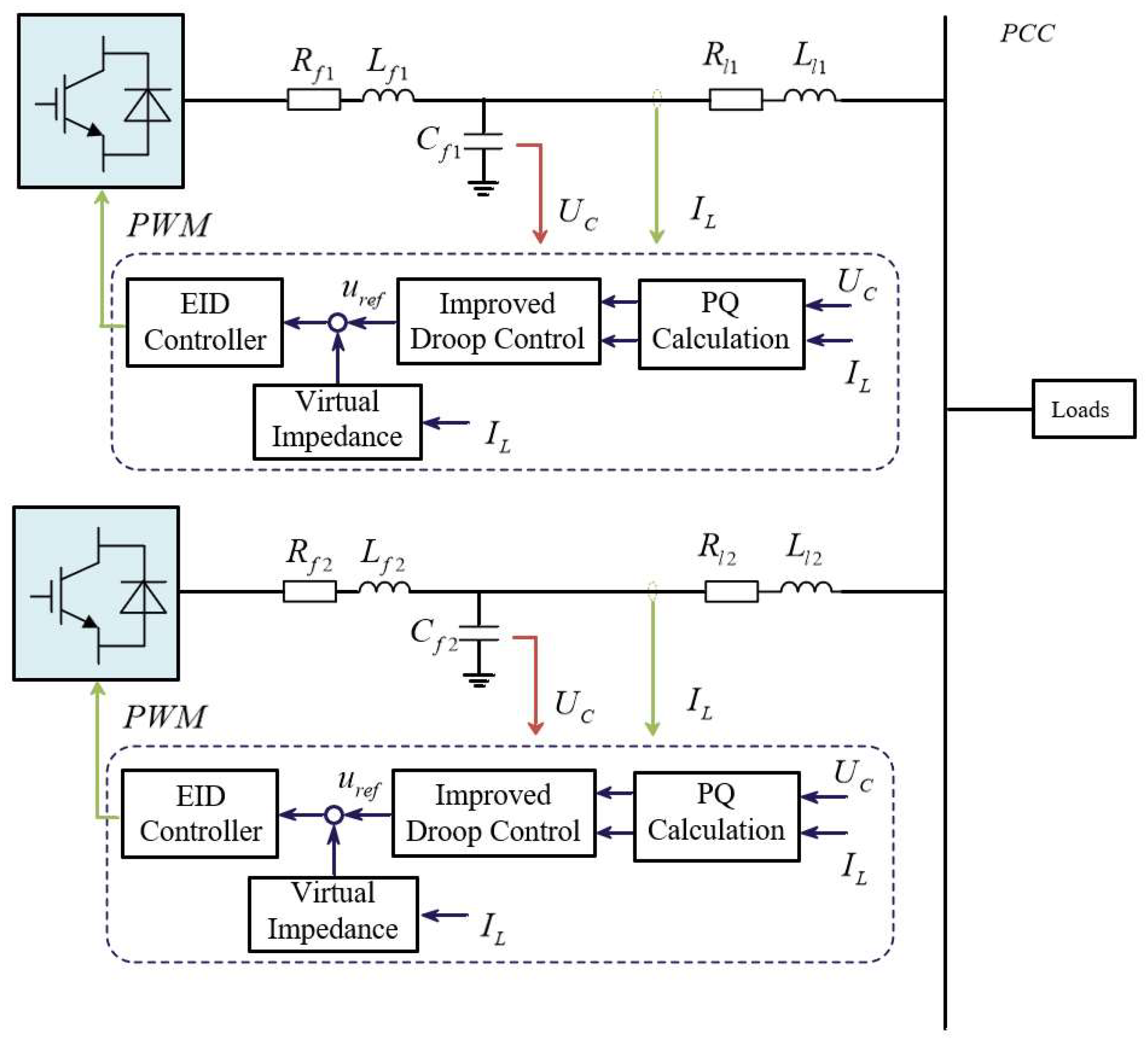
In a microgrid system, distributed power sources need to be connected to the common bus through inverters, and multiple inverters supply power to the loads simultaneously. When microgrids are in islanding mode not connected to the larger grid, the inverter provides voltage support and power output directly to the AC public bus. To address the power sharing and circulating current fluctuation problems in microgrid systems, this paper proposes an improved droop control method based on EID. Figure 1 shows the control topology of the microgrid parallel inverters that includes the improved method proposed in this paper.
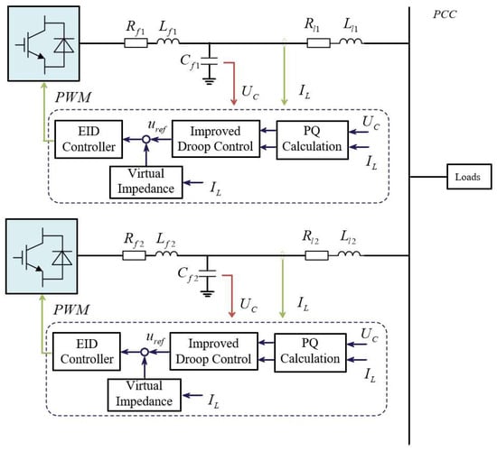
Figure 1.
Parallel inverter control topology incorporating improved methods.
Distributed power is converted through an inverter when connected to a common load, and inductors and capacitors are also required for filtering when the distributed power is connected to an AC bus. The power output from the inverter is calculated by collecting the current through the inductor and the voltage through the capacitor. The synthesized voltage is obtained by the improved transient control method proposed in this paper, the synthetic voltage and the adaptive virtual complex impedance wake-up are superimposed to obtain the reference voltage , is tracked by the reference voltage through the EID-based voltage controller, and finally the PWM wave is generated to control the inverters. The microgrid inverter parallel operation system is formed by multiple inverters controlled by the above proposed control method.
2.2. Modeling and Analysis of Parallel Inverter Systems
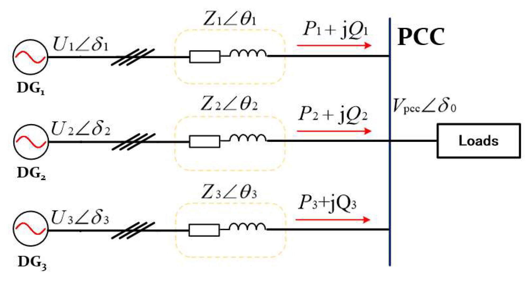
The simplified structure of parallel inverters for islanded microgrids is shown in Figure 2.
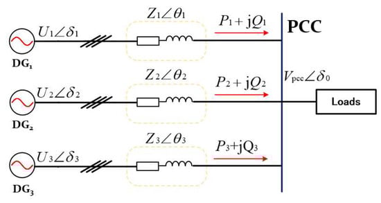
Figure 2.
Simplified structure of parallel inverters for islanded microgrids.
In medium or high voltage microgrids, the inductive impedance in the line plays a major role [27,28,29]. There exists in the feeder impedance. In practical applications, the system power angle is generally very small. At this point there is and . The active and reactive power output from the inverter can be simplified as
When the line is inductive, effective control of the system should be implemented using active-frequency and reactive-voltage droop control. The conventional droop control expression applied to the ith inverter in a system of parallel operation of inverters is
In the above equation, and are the frequency and output voltage in the parallel operation system of microgrid inverters, respectively; and are the rated frequency and rated voltage of the parallel operation system of inverters; and are the rated frequency and rated voltage of the parallel operation system of inverters; and are the active power and reactive power output from the ith inverter in the system after low-pass filtering; m and n are the droop coefficients of the ith inverter, respectively.
When the system works normally, in order to ensure the accuracy of power distribution, the output voltage vector of each inverter in the system is required to be the same, that is , and . Assuming that k is the ratio of droop coefficients between different inverters, in order for the power to be matched, the system must conform to . The output voltage of the ith inverter in the system of parallel operation of inverters is
Through Equation (3), when is satisfied, the output voltage vector of each inverter is the same when the inverter parallel operation system is working normally. To realize the accurate distribution of reactive power output from each inverter in the system, it is not only required that the output voltage vectors of each inverter in the system are the same, but also that the total equivalent output impedance between the inverters in the system satisfies a certain proportionality.
In order to design an inverter controller that meets the application, the inverter system also needs to be modeled. Figure 3 shows a circuit diagram of the simplified inverter system.
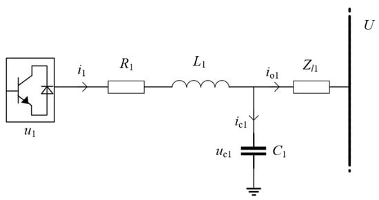
Figure 3.
Circuit diagram of the simplified inverter system.
According to Kirchhoff’s law, the state variables of the system are and , the inputs of the system are and , and the output of the system is . The state and output equations of the inverter system can be obtained
The state equations of the inverter system containing the filter are determined from the modeling in Equation (4). The EID-based voltage controller proposed in this paper is controlled in the dq-axis coordinate system. The voltage controller will be introduced in Section 4 and the derivation of the state equations in the dq-axis coordinate system will be carried out.
3. Improving Droop Control
In the actual operation of the microgrid inverter parallel operation system, there are many disturbing factors in detecting the line impedance parameters, and the measured values will have certain errors. Therefore, it is difficult to make the equivalent output impedance of each inverter in the parallel operation system of microgrid inverters satisfy a certain proportional relationship.
The total output impedance of the inverter affects the stability and dynamic performance of the system. The output impedance is a large percentage of the total output impedance. The working principle of virtual impedance is to multiply the line current by the virtual impedance as a feedback signal, and subtract it from the reference voltage generated by the droop control to generate a new reference voltage. The final system impedance transfer function in the inverters control loop is
Among them, is the closed-loop transfer function of the voltage control loop of the inverter system, is the virtual impedance transfer function assuming superposition, is the output impedance transfer function of the inverter system, and is the feeder impedance transfer function of the inverter loop. When the total impedance of the system is in direct proportion to droop coefficient or in inverse proportion to reactive power capacity, reactive power can be distributed reasonably according to the set capacity.
After introducing virtual impedance, the system impedance of the inverter is approximately inductive at the fundamental frequency . In accordance with the line impedance parameters under different voltage levels [30], the resistance-inductance ratio condition is set as , that is, the phase angle of the system impedance . This design can make the inverter meet the condition of approximate power decoupling. After superimposing the virtual impedance and reference voltage, the amplitudes of system impedances and of inverters at fundamental frequency are in direct proportion to the corresponding droop coefficients and of inverters [31] and in inverse proportion to the set capacity. The design enables the distribution of reactive power to meet the requirements in accordance with the set capacity ratios, while suppressing reactive circulating current. The above requirements can be expressed as the following relationship.
After superimposing the virtual impedance and reference voltage, the virtual impedance is bound to produce a certain voltage dip [10,32], assumed to be . It can be known that , and is expressed as the longitudinal component and the transverse component , respectively:
In parallel inverter systems, the classical approach is usually to superimpose the virtual impedance and the reference voltage generated by the droop control to reduce the power error caused by the feeder impedance. The size of feeder impedance in a shunt inverter system is determined by many factors (feeder length, material), and it is difficult to quickly determine the size of feeder impedance, so the virtual impedance is difficult to be adjusted and is very dependent on the designer’s experience. In this paper, an adaptive virtual complex impedance control method is proposed, which aims to solve the problems of feeder impedance difference and difficulty to adjust the virtual impedance. The inputs in the adaptive virtual impedance controller are active power and reactive power, which are composed of base impedance and adaptive impedance. The adaptive virtual complex impedance of each inverter can be calculated as
and are the adaptive virtual impedance part. is the filter function.
When the output equivalent impedance of the multi-inverter parallel system after the introduction of virtual complex impedance is much larger than the equivalent line impedance, the output line equivalent impedance characteristic of the system is determined by the new equivalent line impedance, and the virtual complex impedance expression needs to be satisfied:
The method of adaptive virtual complex impedance that we adopt when dividing the virtual complex impedance into two parts is that the reference value and the adaptive value, and the adaptive part are transformed by the ratio of active and reactive power to voltage magnitude, respectively [33]. When there is a difference in feeder impedance, the size of the virtual complex impedance is adjusted by setting the adaptive scaling factor to satisfy Equation (6), so as to reduce the power sharing error.
There are two major problems in the traditional droop control system with multiple inverters in parallel, which will affect the power sharing. When there is a mismatch in the equivalent line impedance of the output of the system, it will mainly affect the equal distribution effect of reactive power, because there is a coupling phenomenon between active power and reactive power when the output equivalent line impedance of the system is inductive. Therefore, the equal distribution effect of active power will also be affected. When the multi-parallel inverter system is connected or disconnected from the load, the fluctuation of the common bus voltage amplitude and the instability of frequency in the traditional droop control method will seriously affect the equal distribution of reactive power, affect the response speed of the system, and cause oscillation to the system, and even lead to the instability of the whole system.
For parallel inverter systems, frequent switching of loads leads to fluctuations in the common bus, and power sharing accuracy is affected by bus fluctuations. When there are resistive and inductive feeder impedances, the coupling between active power and virtual impedance can improve the power sharing accuracy, but the superposition of the reference voltage generated by the droop control and the virtual impedance will bring about a certain voltage drop. Therefore, based on the above problems, a new control link is added to the traditional droop control for compensation, and the improved droop control is
Among them, is voltage drop compensation, . The above improvements are carried out in the power outer loop controller of the inverter and will not affect the equivalent output impedance of the system after the introduction of virtual impedance.
The above improvement method is now combined with the droop control with adaptive virtual complex impedance, which further improves the stability of the system by introducing the power change due to voltage drop as a variable into the droop control while introducing the adaptive complex virtual impedance to regulate the impedance of the system. Since the above improvement is carried out in the power outer loop controller of the inverter, it does not affect the equivalent output impedance of the system after the introduction of the adaptive complex virtual impedance.
Compared with the traditional droop control strategy, the strategy proposed in this paper introduces a proportional term and voltage dip compensation in the droop control equation to form a new power outer loop. A virtual complex impedance is introduced into the system equivalent impedance to solve the output power sharing problem due to the mismatch of the system equivalent line impedance.
4. Voltage Controller Based on Equivalent Input Disturbances
The inverter controller is susceptible to perturbations in the reference voltage tracking control link, and the loop current fluctuations between inverter branches have an impact on power sharing and system stability due to impedance differences and sampling perturbations. Figure 4 shows the equivalent circuit diagram containing two inverters. The total output impedance of the system can be expressed as inverter output impedance and feeder impedance .
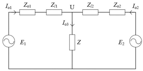
Figure 4.
Equivalent circuit diagram containing two inverters.
By including the equivalent circuit diagram of the two inverters, we can define the loop current between the two inverters as
The total output current of the two inverter circuits is
In a parallel inverter system, a portion of the output current of each loop is consumed by the load side, and the other portion flows between the inverters as a circulating current, thus affecting the power output between the inverters. From (13), when the inverter output voltage is the same but the equivalent output impedance is different, the loop current is proportional to the difference between the total equivalent impedance of the two inverters. When the total equivalent impedance of the inverters is the same but the output voltages are different, the loop current is proportional to the difference between the output voltages of the inverters. When the total equivalent impedance and the output voltages are not the same, the loop current is affected by these two differences.
From a power perspective, each inverter in the parallel inverter system outputs power to the load on the AC bus. Unreasonable power distribution increases the circulating current in the system. Frequent switching of loads leads to power fluctuations, so when loop current is generated in the inverter system, the power fluctuations caused by the loads will generate loop current fluctuations. The instantaneous load switching will produce instantaneous loop current peaks, and excessive loop current fluctuations are very harmful to the power electronics.
Facing the problem of circulating current fluctuation, it is not possible to achieve the ideal control effect in strongly coupled and nonlinear systems such as microgrids, so the idea of EID is considered, which regards the fluctuation of the circulating current as a kind of disturbance and carries out the disturbance suppression to reduce the circulating current fluctuation. Loop currents are included in the inverter system output current. For
where is the output current of the inverter loop. is the loop current of this loop, which is considered here as a disturbance. Through the idea of EID, when there exists a value of loop current disturbance, the parallel inverter system can be re-expressed as
The EID controller-based approach can effectively and equivalently compensate for any form of external perturbation without the need to anticipate the characteristics of the perturbation and the inverse model of the object to be controlled. In (15), the circulating current is regarded as a kind of disturbance external to the system, and then the input in the state equation is ignored according to the superposition theorem. According to the idea of EID, the external disturbance can be converted into a disturbance in the input channel to achieve the condition of suppressing the disturbance. The EID-based state equation in the inverter system can be rewritten as
In the above, we have established the inverter system based on EID. Because designing EID-based controllers generally requires a high level of modeling, it is necessary to model the inverter system. Determining the equation of state facilitates us to design the EID-based reference voltage tracker, and the design of the EID-based voltage controller is described in the following.
For the controlled object with EID in Figure 1, we establish a rotating dq coordinate system for voltage constant reference tracking and design the EID voltage controller under the rotating dq coordinate system. The equation of state in the rotating dq coordinate system, including the disturbances of the circulating current fluctuations, can be derived from (16)
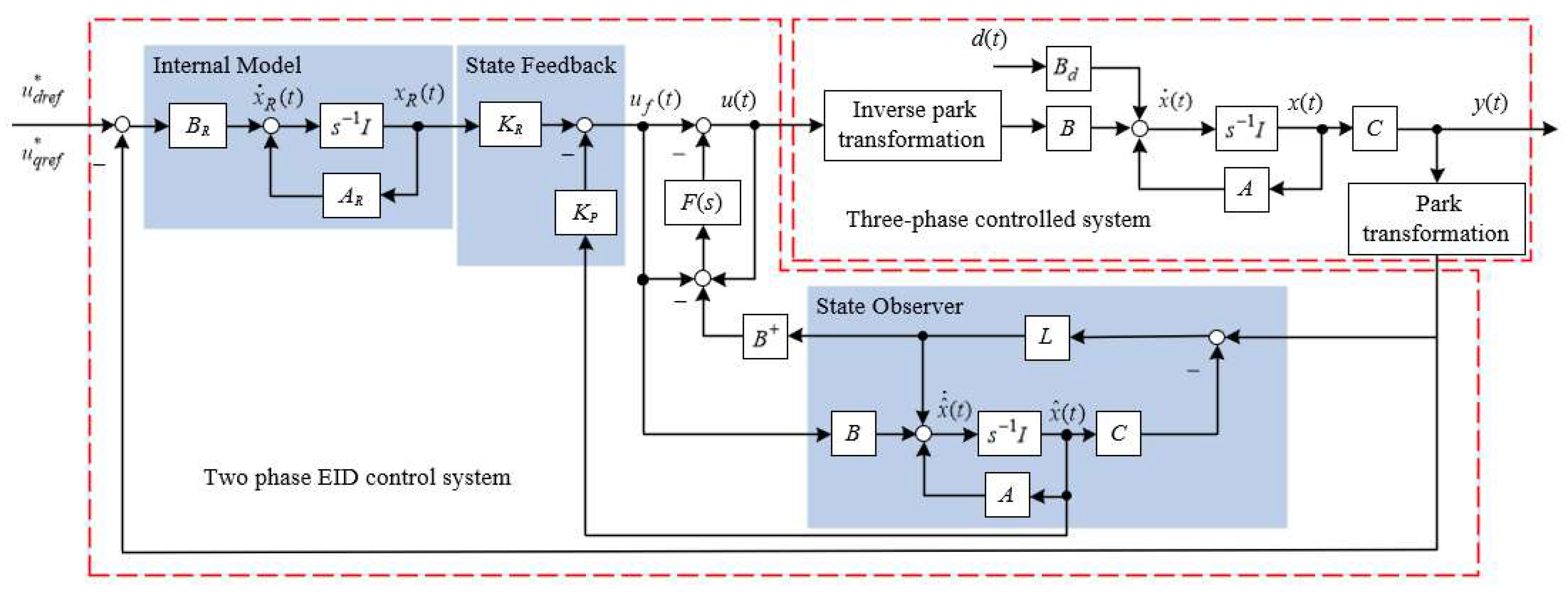
The structure of the EID-based voltage controller is shown in Figure 5. The input to the EID-based voltage controller is the reference voltage generated by the adaptive improved droop controller. The reference voltage undergoes internal modeling and state feedback to ensure tracking stability. The state observer and disturbance estimator perform the estimation of the equivalent input disturbance. Finally, the obtained output is used to generate a PWM wave for inverter control.

Figure 5.
Structure of EID-based voltage controller.
Equivalent input interference suppression, in principle, is used to offset the interference suppression in the input channel by introducing an equivalent input of the same size and in the opposite direction in advance in the input channel. The equivalent circulation fluctuation disturbance based on the EID idea is
In the voltage controller structure
where is the inverse matrix of , is the filter function, and is the internal model.
The input signal containing equivalent input interference is obtained after filtering
From Equation (4), the system is controllable and observable. An augmented generalized state system consists of internal models and devices. In the voltage controller design process, optimal control theory is used for parameter selection to ensure the stability of the voltage controller system. Parameters , , and are determined using the minimization performance index in optimal control theory [26].
5. Simulation Experiments and Analysis
In this paper, a two-inverter system based on adaptive improved droop control and EID is proposed based on MATLAB/Simulink as shown in Figure 1. Validation of an EID-based reference voltage tracker and an adaptive improved droop control method is carried out in relation to the parallel inverter system in the presence of feeder impedance differences. The parameters used for the experiment are shown in Table 1.

Table 1.
Simulation parameters.
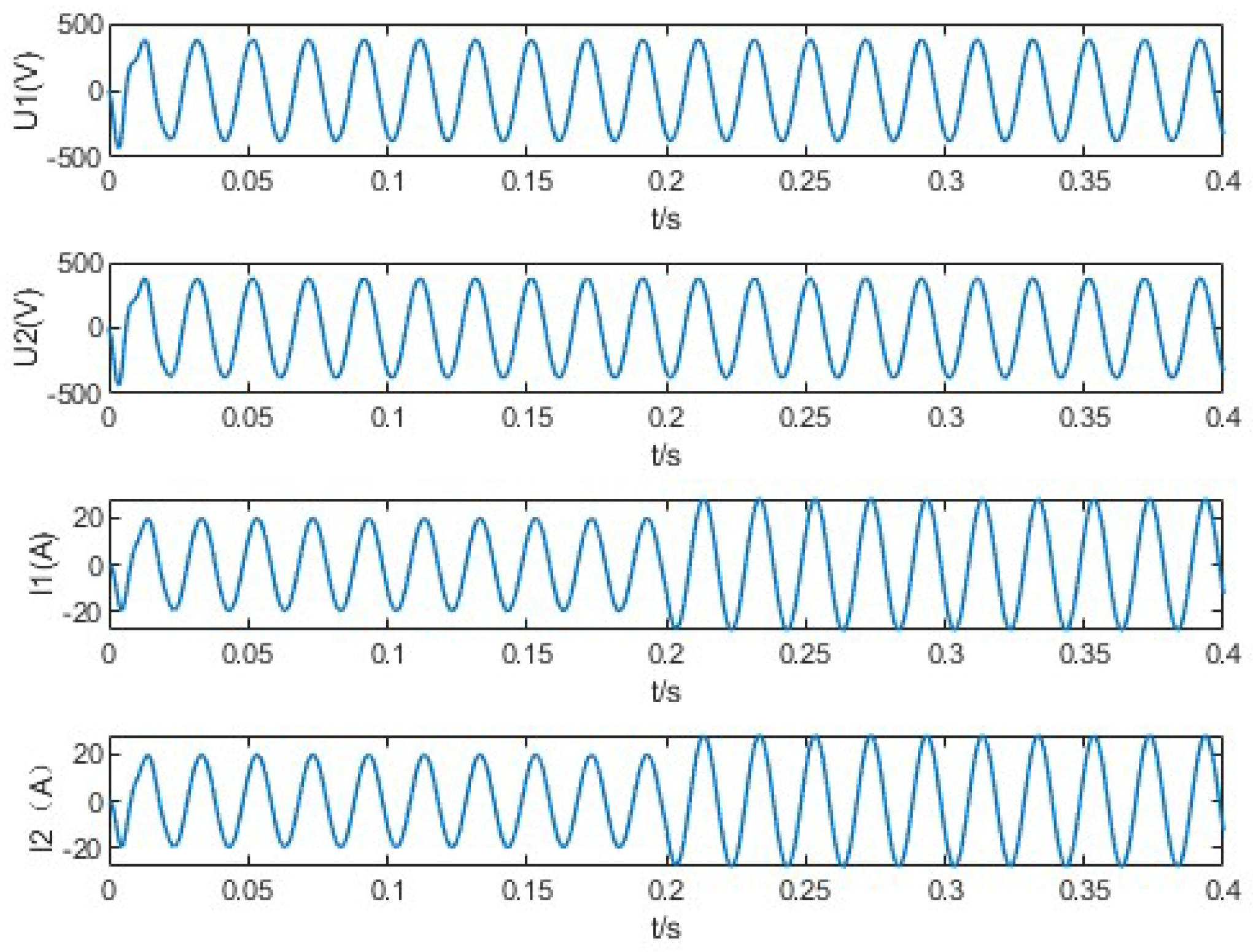
Firstly, verify the tracking performance and stability of the voltage controller based on the EID method. The same parameters are given to the inverter to ensure that there is no power error in the output of the inverter, so there is no difference in the impedance of the feeder, and the reference voltage only needs to be generated by the classical droop control method. The public bus initially carries a certain load and increases the load at 0.2 s. The initial public bus load is 10 kW active power and 4 kVar reactive power. The public bus added loads are 4 kW active power and 2 kVar reactive power. Verify the tracking performance of EID-based voltage controllers through load switching. Figure 6 shows the voltage and current waveform of a certain phase of the reference voltage tracker based on EID proposed in this paper. The initial voltage tracking of the voltage controller requires only 0.01 s. Current tracking takes only half a cycle. The simulation results show that the reference voltage controller based on EID can track the voltage very quickly and ensure the stability of the system.
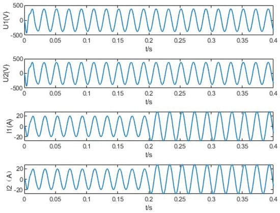
Figure 6.
Voltage and current waveform of a certain phase of the reference voltage tracker based on EID.
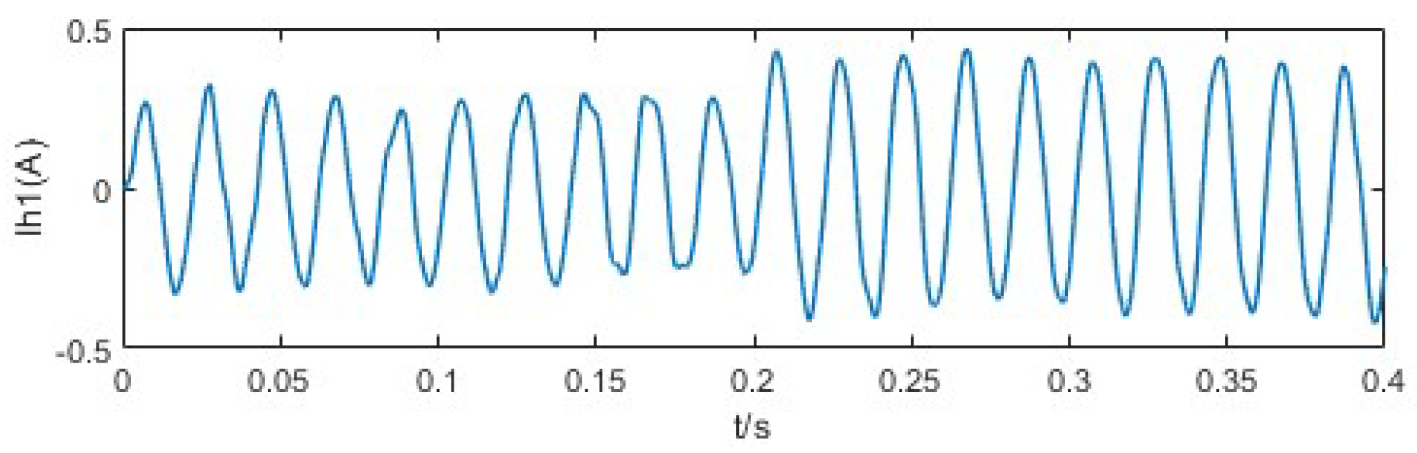
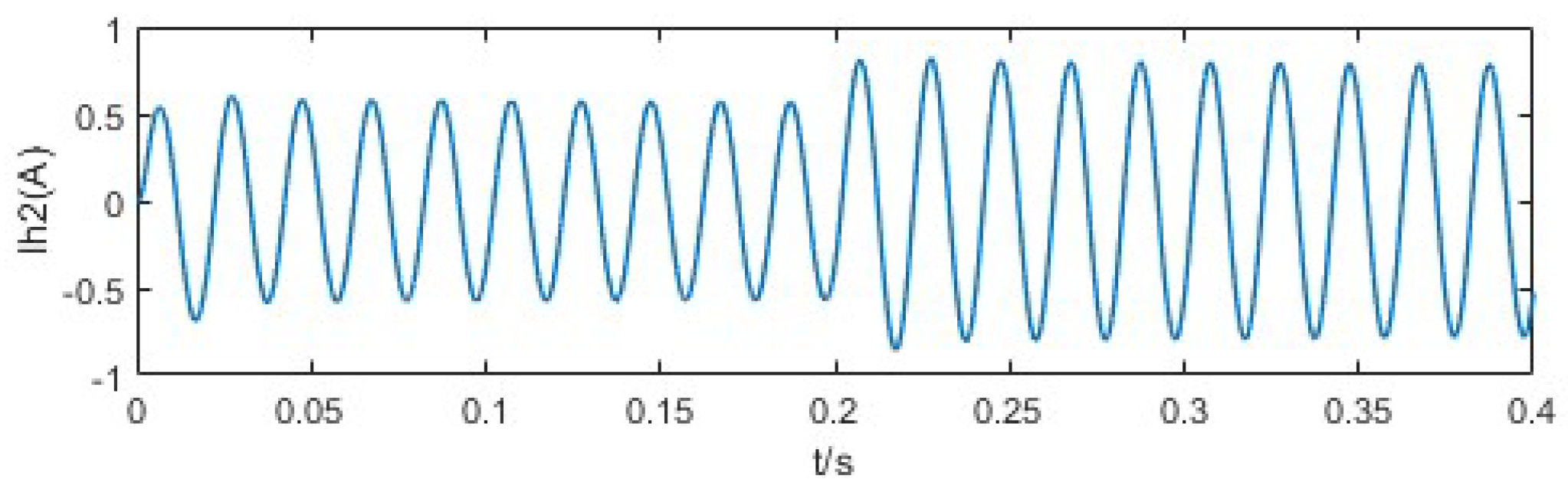
To verify the circulating current fluctuation suppression effect of the EID-based voltage controller, the feeder impedance difference between inverters is set, and the other working conditions are the same as the previous validation experiment. The EID-based reference voltage tracker is compared with the dual-loop PI-based reference voltage tracker to verify the suppression effect of circulating current fluctuation. Figure 7 shows the loop current waveform of the EID-based reference voltage tracker; the initial loop current is 0.3 A, and the loop current is 0.4 A after increasing the load. Figure 8 shows the loop current waveform of the dual-loop PI-based reference voltage tracker. The initial loop current is 0.6 A, and the loop current after adding load is 0.8 A. Comparison simulation experiments show that the EID-based reference voltage tracker has stronger anti-interference capability and loop current fluctuation suppression performance compared with the dual-loop PI-based reference voltage tracker, and the EID-based reference voltage tracker can ensure the safety and reliability of power quality.
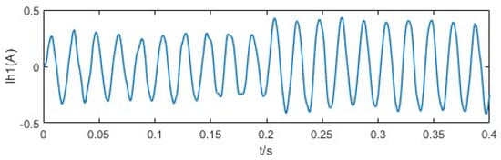
Figure 7.
Loop current waveform of the EID−based reference voltage tracker.
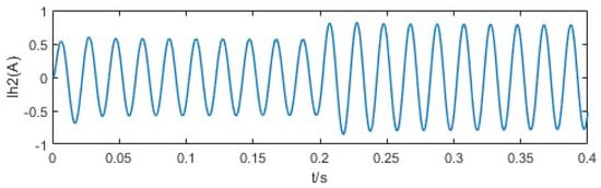
Figure 8.
Loop current waveform of the dual−loop PI−based reference voltage tracker.
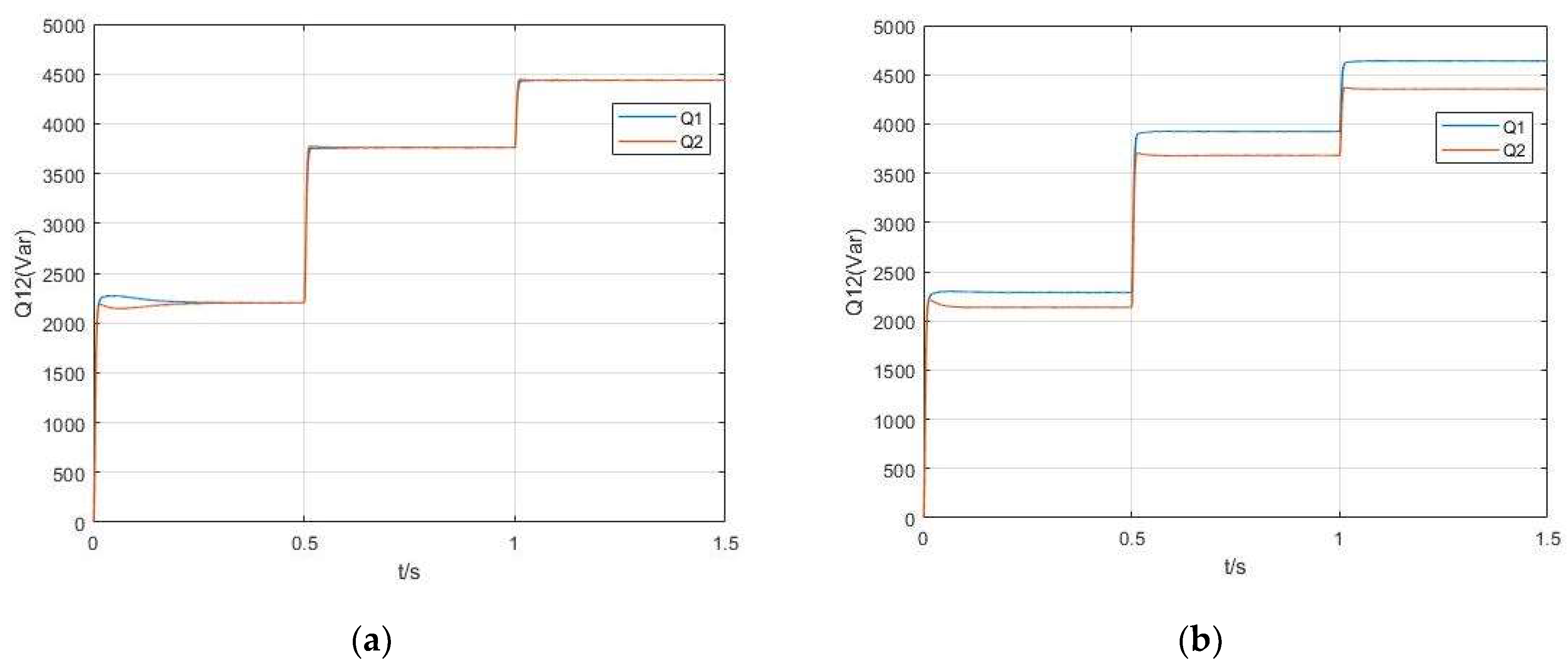
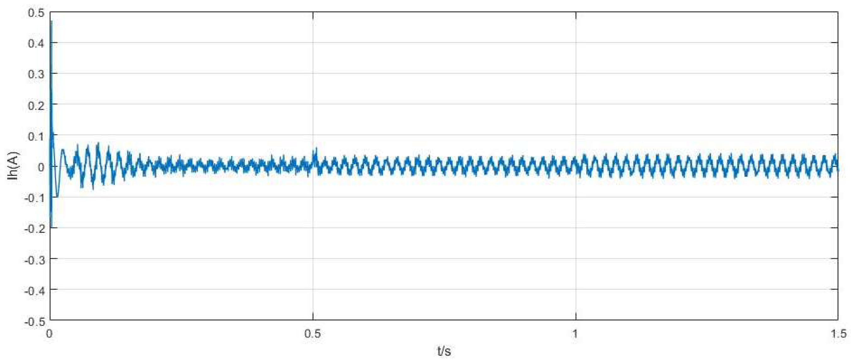
Validate the improved adaptive droop control and EID-based method proposed in this paper. Comparative simulation experiments are carried out for reactive power as well as loop current suppression. The common load are initially 16 kW and 2 kVar reactive power, and the feeder impedance difference between the inverters is set. At 0.5 s, increase the load to 3 kW active power and 2 kVar reactive power. At 1 s increase the load to 2 kW active power and 1 kVar reactive power. Figure 9a shows the reactive power output for the combination of conventional droop control and EID voltage controller. Figure 9b shows the active and reactive power output for the combination of modified droop control and EID voltage controller. Comparing the reactive power output of the inverter with both controllers, the improved droop control has no significant reactive power sharing error between the inverters, while the conventional droop control still has a large reactive power error. Figure 10 shows the circulating currents when the improved droop control and EID methods are used. It can be seen that the value of the circulating current is less than 0.1 A, which is smaller compared to Figure 7 and Figure 8, and the fluctuation of the circulating current is smaller. Simulation experiments show that the improved droop controller based on EID has smaller power sharing error and better immunity than the conventional controller, which can improve the stability and transmission efficiency of the system.

Figure 9.
(a) Improved droop control power output based on EID; (b) conventional droop control power output based on EID.
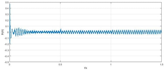
Figure 10.
Improved droop control circulating current based on EID.
To address the problem of poor suppression of circulating current fluctuation in double closed-loop PI control, a voltage controller based on equivalent input disturbance (EID) is proposed. Aiming at the problems of power sharing error due to impedance difference and voltage drop due to virtual impedance, a reference voltage generator based on virtual complex impedance and improved droop control is proposed. Simulation experiments experimentally demonstrate that the method proposed in this paper is better than the traditional control method in terms of stability and immunity, and can effectively reduce the circulating current fluctuation and power sharing error between inverters.
6. Conclusions
The power sharing and circulation problems in parallel inverter systems affect the safety and stability of microgrid operation. It also affects energy efficiency and sustainability. Aiming at the problems existing in the traditional droop control, the model of a parallel inverter system is analyzed, and adaptive virtual complex impedance is proposed to reduce the power error in order to further increase power sharing and improve upon the conventional droop control method. Aiming at the problem of large fluctuation of loop current when the load changes on the common bus, the EID idea is adopted for interference suppression, so as to suppress the influence of the circulation and reduce the power sharing error. The simulation results show that the proposed method can improve the power sharing accuracy and system stability.
Author Contributions
Conceptualization, M.D.; Methodology, M.D., Z.T. and R.Y.; Software, Z.T. and S.T.; Validation, Z.T.; Formal analysis, B.H.; Investigation, B.H. and S.T.; Resources, B.H.; Data curation, S.T.; Writing— original draft, M.D. and Z.T.; Writing—review & editing, M.D.; Visualization, Z.T.; Supervision, R.Y.; Project administration, M.D. and R.Y.; Funding acquisition, M.D. All authors have read and agreed to the published version of the manuscript.
Funding
This research was funded by the National Natural Science Foundation of China under Grant 61503348.
Data Availability Statement
The data presented in this study are available in this article.
Conflicts of Interest
Author Bo Hu was employed by the company Global Energy Interconnection Group Co., Ltd. The remaining authors declare that the research was conducted in the absence of any commercial or financial relationships that could be construed as a potential conflict of interest.
References
- Wang, J.; Zhao, G. Simulation and Characteristics Analysis of Multiple Wind Generators in Large-Scale Wind Farms Based on Simplified Model. Electronics 2020, 9, 1994. [Google Scholar] [CrossRef]
- Cao, X.; Wang, J.; Zeng, B. Networked microgrids planning through chance constrained stochastic conic programming. IEEE Trans. Smart Grid 2019, 10, 6619–6628. [Google Scholar] [CrossRef]
- Mirafzal, B.; Adib, A. On grid-interactive smart inverters: Features and advancements. IEEE Access 2020, 8, 160526–160536. [Google Scholar] [CrossRef]
- Tooryan, F.; HassanzadehFard, H.; Collins, E.R.; Jin, S.; Ramezani, B. Smart integration of renewable energy resources, electrical, and thermal energy storage in microgrid applications. Energy 2020, 212, 118716. [Google Scholar] [CrossRef]
- Bella, S.; Chouder, A.; Djerioui, A. Circulating currents control for parallel grid-connected three-phase inverters. In Proceedings of the 2018 International Conference on Electrical Sciences and Technologies in Maghreb (CISTEM), IEEE, Algiers, Algeria, 28–31 October 2018; pp. 1–5. [Google Scholar]
- Guerrero, J.M.; Chandorkar, M.; Lee, T.L. Advanced control architectures for intelligent microgrids—Part I: Decentralized and hierarchical control. IEEE Trans. Ind. Electron. 2012, 60, 1254–1262. [Google Scholar] [CrossRef]
- Guerrero, J.M.; Chandorkar, M.; Lee, T.L. Output impedance design of parallel-connected UPS inverters with wireless load-sharing control. IEEE Trans. Ind. Electron. 2005, 52, 1126–1135. [Google Scholar] [CrossRef]
- Guerrero, J.M.; Chandorkar, M.; Lee, T.L. Decentralized control for parallel operation of distributed generation inverters using resistive output impedance. IEEE Trans. Ind. Electron. 2007, 54, 994–1004. [Google Scholar] [CrossRef]
- Hoang, T.V.; Lee, H.H. An adaptive virtual impedance control scheme to eliminate the reactive-power-sharing errors in an islanding meshed microgrid. IEEE J. Emerg. Sel. Top. Power Electron. 2017, 6, 966–976. [Google Scholar] [CrossRef]
- Zhang, J.; Shu, J.; Ning, J.; Huang, L.; Wang, H. Enhanced proportional power sharing strategy based on adaptive virtual impedance in low-voltage networked microgrid. IET Gener. Transm. Distrib. 2018, 12, 2566–2576. [Google Scholar] [CrossRef]
- Dou, C.; Zhang, Z.; Yue, D.; Song, M. Improved droop control based on virtual impedance and virtual power source in low-voltage microgrid. IET Gener. Transm. Distrib. 2017, 11, 1046–1054. [Google Scholar] [CrossRef]
- Xu, H.; Zhang, X.; Liu, F.; Shi, R.; Yu, C.; Cao, R. A reactive power sharing strategy of VSG based on virtual capacitor algorithm. IEEE Trans. Ind. Electron. 2017, 64, 7520–7531. [Google Scholar] [CrossRef]
- Zhu, Y.; Zhuo, F.; Wang, F.; Liu, B.; Gou, R.; Zhao, Y. A virtual impedance optimization method for reactive power sharing in networked microgrid. IEEE Trans. Power Electron. 2015, 31, 2890–2904. [Google Scholar] [CrossRef]
- He, J.; Li, Y.W.; Blaabjerg, F. An enhanced islanding microgrid reactive power, imbalance power, and harmonic power sharing scheme. IEEE Trans. Power Electron. 2015, 30, 3389–3401. [Google Scholar] [CrossRef]
- Moslemi, R.; Mohammadpour, J. Accurate reactive power control of autonomous microgrids using an adaptive virtual inductance loop. Electr. Power Syst. 2015, 129, 142–149. [Google Scholar] [CrossRef]
- Mahmood, H.; Michaelson, D.; Jiang, J. Reactive Power Sharing in Islanded Microgrids Using Adaptive Voltage Droop Control. IEEE Trans. Smart Grid 2015, 6, 3052–3060. [Google Scholar] [CrossRef]
- Li, P.; Wang, X.; Lee, W.J.; Xu, D. Dynamic Power Conditioning Method of Microgrid Via Adaptive Inverse Control. IEEE Trans. Power Deliv. 2015, 30, 906–913. [Google Scholar] [CrossRef]
- Zhang, H.; Kim, S.; Sun, Q.; Zhou, J. Distributed Adaptive Virtual Impedance Control for Accurate Reactive Power Sharing Based on Consensus Control in Microgrids. IEEE Trans. Smart Grid 2017, 8, 1749–1761. [Google Scholar] [CrossRef]
- Bai, X.; Miao, H.; Zeng, C. Improved Droop Control Strategy for Reactive Power Sharing of Parallel Inverters in Low-Voltage Microgrid. In Proceedings of the 2019 IEEE Innovative Smart Grid Technologies-Asia (ISGT Asia), Chengdu, China, 21–24 May 2019; pp. 2538–2543. [Google Scholar]
- Shafiee, Q.; Guerrero, J.M.; Vasquez, J.C. Distributed secondary control for islanded microgrids—A novel approach. IEEE Trans. Power Electron. 2014, 29, 1018–1031. [Google Scholar] [CrossRef]
- Romero, M.E.; Seron, M.M. Ultimate boundedness of voltage droop control with distributed secondary control loops. IEEE Trans. Smart Grid 2019, 10, 4107–4115. [Google Scholar] [CrossRef]
- Micallef, A.; Apap, M.; Spiteri-Staines, C.; Guerrero, J.M.; Vasquez, J.C. Reactive power sharing and voltage harmonic distortion compensation of droop controlled single phase islanded microgrids. IEEE Trans. Smart Grid 2014, 5, 1149–1158. [Google Scholar] [CrossRef]
- Simpson-Porco, J.W.; Shafiee, Q.; Dörfler, F.; Vasquez, J.C.; Guerrero, J.M.; Bullo, F. Secondary frequency and voltage control of islanded microgrids via distributed averaging. IEEE Trans. Ind. Electron 2015, 62, 7025–7038. [Google Scholar] [CrossRef]
- Ye, M.; Ding, M.; Li, D.; Fang, Z.; Wang, Q.; Chen, L. Robust interference suppression of three phase structural uncertainty inverter system based on equivalent input interference method. In Proceedings of the 2022 International Power Electronics Conference (IPEC-Himeji 2022-ECCE Asia), Himeji, Japan, 15–19 May 2022; pp. 1343–1347. [Google Scholar]
- She, J.H.; Fang, M.; Ohyama, Y.; Hashimoto, H.; Wu, M. Improving disturbance-rejection performance based on an equivalent-input disturbance approach. IEEE Trans. Ind. Electron. 2008, 55, 380–389. [Google Scholar] [CrossRef]
- Ding, M.; She, J.; Yokoyama, R.; Wu, M.; Cao, W. Two-loop power-flow control of grid-connected microgrid based on equivalent-input-disturbance approach. IEEJ Trans. Electr. Electron. Eng. 2015, 10, 36–43. [Google Scholar] [CrossRef]
- Hirase, Y.; Abe, K.; Sugimoto, K.; Sakimoto, K.; Bevrani, H.; Ise, T. A novel control approach for virtual synchronous generators to suppress frequency and voltage fluctuations in microgrids. Appl. Energy 2018, 210, 699–710. [Google Scholar] [CrossRef]
- He, J.; Pan, Y.; Liang, B.; Wang, C. A simple decentralized islanding microgrid power sharing method without using droop control. IEEE Trans. Smart Grid 2018, 9, 6128–61139. [Google Scholar] [CrossRef]
- An, R.; Liu, Z.; Liu, J. Successive-Approximation-Based Virtual Impedance Tuning Method for Accurate Reactive Power Sharing in Islanded Microgrids. IEEE Trans. Power Electron 2021, 36, 87–102. [Google Scholar] [CrossRef]
- Qiao, J.P. Research on Microgrid Inverter Droop Control Strategy; Anhui University of Technology: Ma’anshan, China, 2022. [Google Scholar]
- Hu, Y.; Xiang, J.; Peng, Y.; Yang, P.; Wei, W. Decentralised control for reactive power sharing using adaptive virtual impedance. IET Gener. Transm. Distrib. 2018, 12, 1198–1205. [Google Scholar] [CrossRef]
- Le Minh, P.; Xuan, H.P.; Duc, D.H.; Minh, H.N. Control of power sharing in an island microgrid using virtual impedance. In Proceedings of the International Conference on System Science & Engineering, Ho Chi Minh City, Vietnam, 21–23 July 2017; pp. 154–159. [Google Scholar]
- Fan, B.; Li, Q.; Wang, W.; Yao, G.; Ma, H.; Zeng, X.; Guerrero, J.M. A novel droop control strategy of reactive power sharing based on adaptive virtual impedance in microgrids. IEEE Trans. Ind. Electron. 2021, 69, 11335–11347. [Google Scholar] [CrossRef]


Disclaimer/Publisher’s Note: The statements, opinions and data contained in all publications are solely those of the individual author(s) and contributor(s) and not of MDPI and/or the editor(s). MDPI and/or the editor(s) disclaim responsibility for any injury to people or property resulting from any ideas, methods, instructions or products referred to in the content. |
© 2024 by the authors. Licensee MDPI, Basel, Switzerland. This article is an open access article distributed under the terms and conditions of the Creative Commons Attribution (CC BY) license (https://creativecommons.org/licenses/by/4.0/).