1. Introduction
Vacuum pump technology, as an indispensable part of the modern industrial field, has demonstrated its extensive and profound application value in multiple key areas such as petroleum, the chemical industry, chip manufacturing, and the nuclear industry. This technology not only enhances efficiency and safety in the production process, but also drives continuous innovation and development in related industries. To improve the operational efficiency of vacuum pumps, they are currently driven primarily by canned permanent magnet synchronous motors (CPMSMs) [
1,
2].
CPMSMs are a type of special motor used for conveying media that are high temperature, high pressure, corrosive, radioactive, toxic, harmful, flammable, and explosive [
3]. These motors are widely used due to their exceptional efficiency, zero leakage risk, convenient maintenance procedures, and high reliability. Compared to conventional permanent magnet synchronous motors, this type of motor features specially designed built-in stator and rotor shielding sleeves that separate the motor’s rotor core and stator windings from the conveyed media, preventing corrosion to the motor components [
4,
5,
6,
7].
In recent years, as energy efficiency has gained increasing attention, motors are typically powered by variable frequency drives to operate over a wider speed range [
8]. The use of variable frequency drives also introduces a significant amount of current time harmonics, especially the 6k ± 1 (where k = 1, 2, 3, ...) order harmonics such as the 5th, 7th, 11th, 13th, etc. [
9]. Research has shown that these harmonics can affect the internal magnetic field of motors, potentially causing distortion in the air-gap magnetic field [
10]. Magnetic field distortions inevitably alter the distribution of magnetic flux in the motor, affecting the leakage flux distribution. The leakage flux coefficient is commonly used to describe the motor’s magnetic flux leakage. This coefficient not only reflects the utilization rate of the permanent magnet, but also indicates the motor’s resistance to demagnetization. Therefore, an in-depth and accurate analysis of the impact of inverter time-harmonic currents on the motor’s leakage flux coefficient is crucial for improving the utilization rate of permanent magnets and optimizing motor performance.
The interpolar magnetic flux leakage in motors exists within the axial length of the armature core and affects the core energy conversion process, directly influencing the output torque and efficiency. This paper primarily calculates the interpolar magnetic flux leakage in permanent magnet shielded motors. The magnetic flux generated by the permanent magnets is divided into two parts: one part passes through the air gap and links with the armature winding, known as the main flux; the other part does not link with the armature winding and is called the leakage flux. The sum of the main flux and the leakage flux is the total flux. The leakage flux coefficient is the ratio of the total flux to the main flux [
11,
12,
13].
Numerous scholars, both domestically and internationally, have conducted extensive research on the topic of leakage flux coefficients, yielding substantial findings. This paper calculates the no-load leakage coefficient by establishing the analytical model of the no-load magnetic coefficient. It shows that the bridge size has an important effect on the no-load magnetic coefficient [
14]. Reference [
15] derived the variation laws of main and side flux in the stator poles of interleaved permanent magnet linear rotary motors using analytical methods. A three-dimensional flux leakage calculation model suitable for different motor operating principles was established, and both rotational and rectilinear back electromotive forces (EMFs) were calculated. To simplify the calculation process of the leakage flux coefficient, Sung Gu Lee and others proposed a calibration coefficient using information on parameters such as permanent magnet materials in the motor, allowing two-dimensional finite element computations to replace three-dimensional ones, thus reducing computation time [
16]. Jun Zhu and Shuaihui Li aim to study the relationship between the leakage flux coefficient and the coreless axial magnetic field permanent magnet synchronous generator size, obtaining the expressions of the leakage flux coefficient [
17]. Reference [
18] improved the subdomain model, successfully alleviating the leakage flux issue in surface-mounted permanent magnet synchronous motors under no-load conditions, significantly enhancing the accuracy of magnetic field calculations. Reference [
19] proposed a new magnetic circuit model, using the proposed magnetic circuit model and the magnetic flux division law to calculate the leakage flux of each part of the motor in detail. This method significantly reduced the time consumed by motor design and increased the accuracy of the design algorithm.
However, the aforementioned studies focused on the calculation methods of the leakage flux coefficient and the impact of motor size parameters on the leakage flux coefficient without addressing the influence of current time harmonics under the inverter supply on the leakage flux coefficient of CPMPMs. Therefore, this paper delves into the impact of current time harmonics on the leakage flux coefficient of CPMSMs through finite element analysis. This research holds significant implications for the design and operation of CPMPMs powered by inverters.
2. Method for Calculating Leakage Flux Coefficient and Motor Model
A frequency converter is a type of power electronic converter whose core function is to convert a fixed-frequency alternating current (AC) into a variable-frequency AC to achieve precise control of the motor speed. This paper focuses on the study of the magnetic leakage coefficient of CPMSMs. We used winding excitation currents to simulate non-sinusoidal currents under frequency converter supply conditions and analyzed its impact on the magnetic leakage coefficient of CPMSMs. For this reason, this chapter provides a detailed introduction to the motor parameters of CPMSMs and further analyzes the calculation methods for the magnetic leakage coefficient.
2.1. Motor Parameters
This paper focuses on a 1.5 kW, 9000 RPM CPMSM as the research subject, with the main parameters of the motor shown in
Table 1. It should be noted that, to cater to the special operating conditions of high temperature, high pressure, and strong acidic or alkaline environments for CPMSMs, the motor employs austenitic stainless steel SUS316 as the material for the shielding casing.
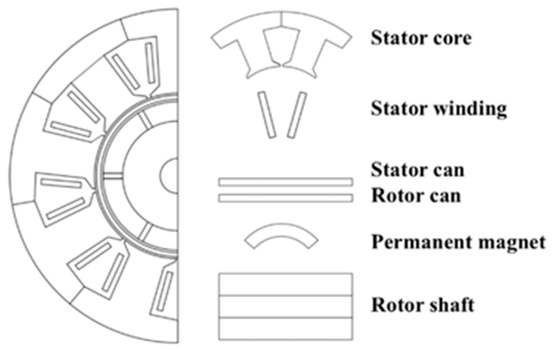
The primary simulation tool used in this study is Ansys Maxwell 19.1, a widely used electromagnetic field simulation software suitable for various motor designs and analyses. In this research, based on the parameters in
Table 1, we utilized Maxwell to establish the two-dimensional finite element model shown in
Figure 1 to analyze the magnetic field distribution of the CPMSMs. To simplify the analysis process, the following assumptions were made:
(1) The inherent characteristics of the inverter switching devices and the harmonic currents caused by dead time are not considered.
(2) The governing equations and boundary conditions for the finite element computational model are as follows [
20]:
In the equation, Az represents the magnetic vector potential, ν denotes the magnetic permeability, σ is the electrical conductivity, Js stands for current density, and Γ represents the external boundary condition.
2.2. Magnetic Flux Density Integration Method
Since the tangential magnetic flux density in the air gap of the CPMSM is much smaller than the radial magnetic flux density and the radial magnetic flux density directly affects the output torque of the motor, this paper only considers the radial magnetic flux density. The formula for calculating the radial magnetic flux density [
21] is as follows:
In the equation, Br is the radial component of magnetic flux density, Bx is the component of magnetic flux density along the X-axis, By is the component of magnetic flux density along the Y-axis, and θ is the angle between the magnetic flux density and the X-axis.
The magnetic flux density integration method is used to calculate the total magnetic flux density in a certain area of the magnetic field, which is crucial for describing the distribution of the magnetic field inside the motor. Using this method, the leakage flux coefficient can be expressed as [
14] follows:
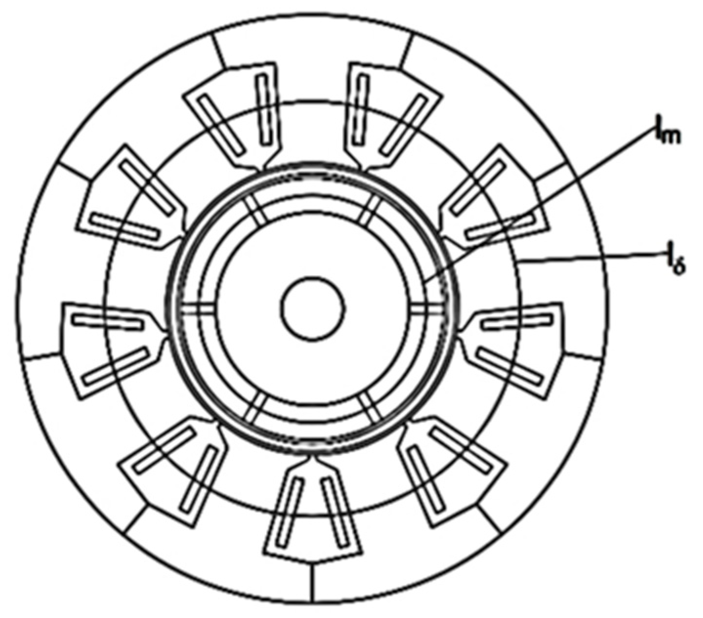
In the equation, Φm represents the total magnetic flux density, Φδ denotes the main magnetic flux density, lm is the integration path of the total magnetic circuit, Bm is the radial magnetic flux density along the integration path of the total magnetic circuit, lδ is the integration path of the main magnetic circuit, and Bδ is the radial magnetic flux density along the integration path of the main magnetic circuit.
The magnetic flux density integration method is used to solve for the leakage flux coefficient, with the total magnetic flux and main magnetic flux integration paths illustrated in
Figure 2.
3. The Effect of Time-Harmonic Currents from Frequency Converters on the Leakage Flux Coefficient of CPMSM
In order to determine the influence of time-harmonic currents from the inverter on the leakage flux coefficient of the CPMSM, this study calculated the leakage flux coefficients of the motor under seven different sets of harmonic current excitations. Since inverter supplies usually produce significant fifth and seventh harmonic currents [
22], the calculation primarily considered the impact of these fifth and seventh harmonics on the leakage flux coefficient. Under the inverter supply, the ratio of each harmonic amplitude to the fundamental wave amplitude generally varies within the range of 1–10% [
23]. Based on this, certain amplitudes of harmonic currents are selected to discuss their impact on the leakage flux coefficient.
When the motor is powered by an inverter, the stator winding contains not only the fundamental wave current but also the
h-th harmonic. At this time, the expression for the stator current is as follows [
24,
25]:
In the equation, h represents the order of the time harmonic, which is a positive integer greater than or equal to 1, Ih denotes the current amplitude corresponding to the h-th time harmonic, and ωh represents the electrical angular frequency of the h-th current.
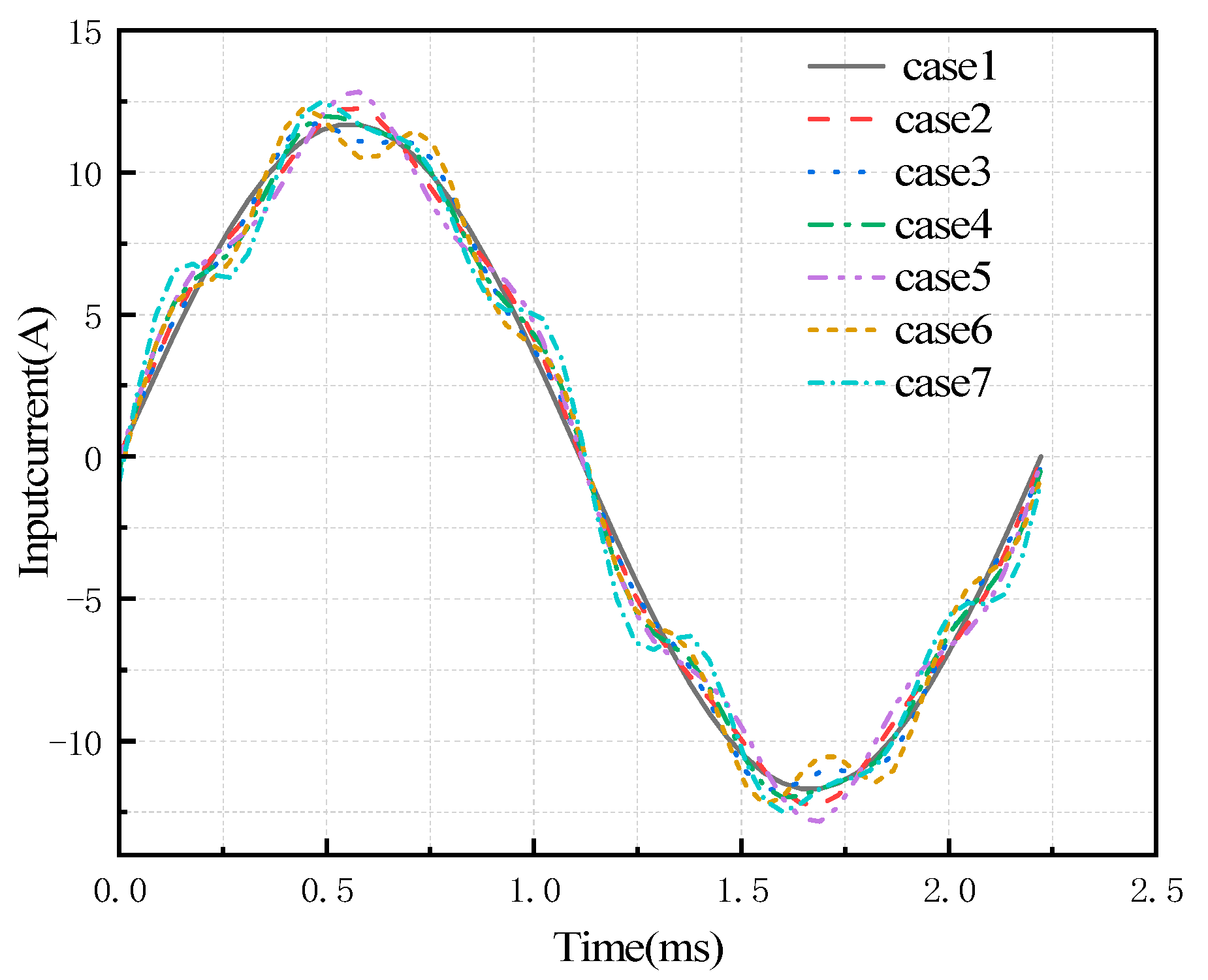
The current waveform distortion caused by harmonics directly affects the magnetic field distribution inside the motor, thereby influencing the leakage flux coefficient. To more intuitively observe the changes in the harmonic current waveforms, the current waveforms of phase A winding under seven sets of excitations are presented, as shown in
Figure 3. To simplify the legend in
Figure 3 and ensure its completeness, please refer to
Table 2 for the specific current excitation settings.
3.1. Magnetic Field Distribution and Magnetic Flux Den-Sity Amplitude
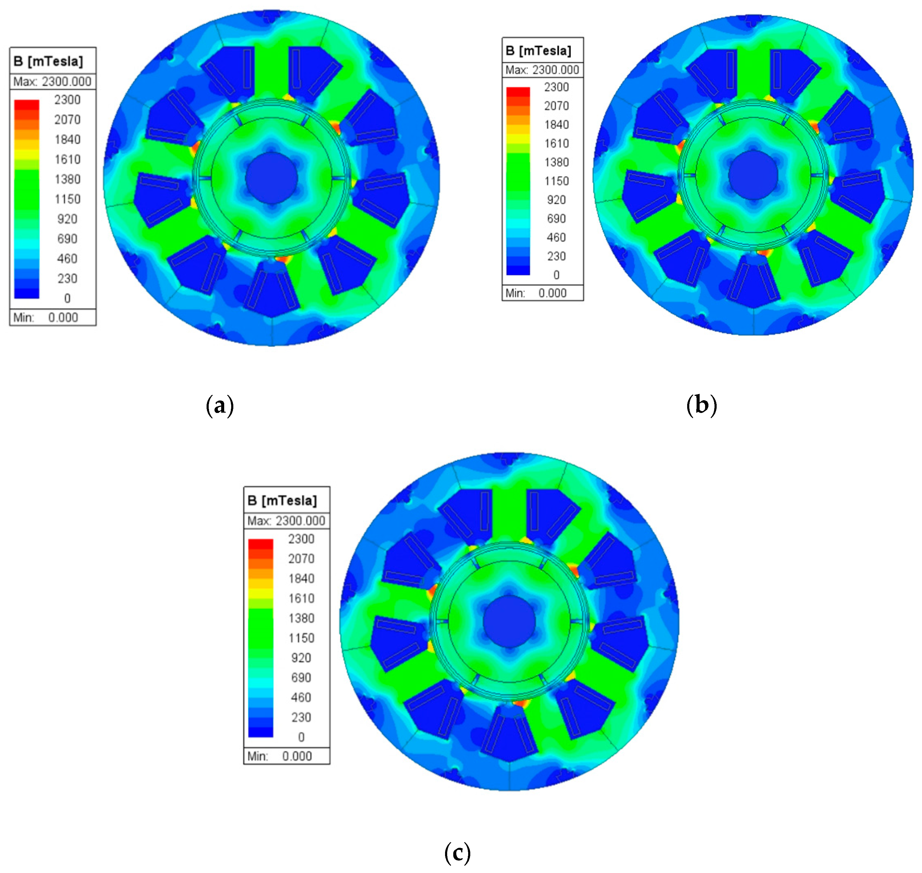
This section analyzes the magnetic field distribution in the motor under sinusoidal and non-sinusoidal excitations using a two-dimensional finite element model of the motor, with the results shown in
Figure 4.
From
Figure 4, it can be seen that under the three excitation conditions, the magnetic flux density distribution in the motor is relatively uniform. Additionally, as the order of harmonics in the current excitation increases, the maximum magnetic flux density in the motor changes. When the fifth harmonic is present, the maximum magnetic flux density decreases from 2.21 T under fundamental excitation to 2.09 T, a reduction of 5.43%. When the seventh harmonic is present, the maximum magnetic flux density decreases from 2.21 T under fundamental excitation to 2.14 T, a reduction of 3.17%.
When the magnetic flux density contains a significant amount of harmonic components, the magnetic field distribution may become more complex. This distortion causes changes in the air-gap magnetic field of the motor, thereby affecting the magnitude and distribution of the leakage flux [
26,
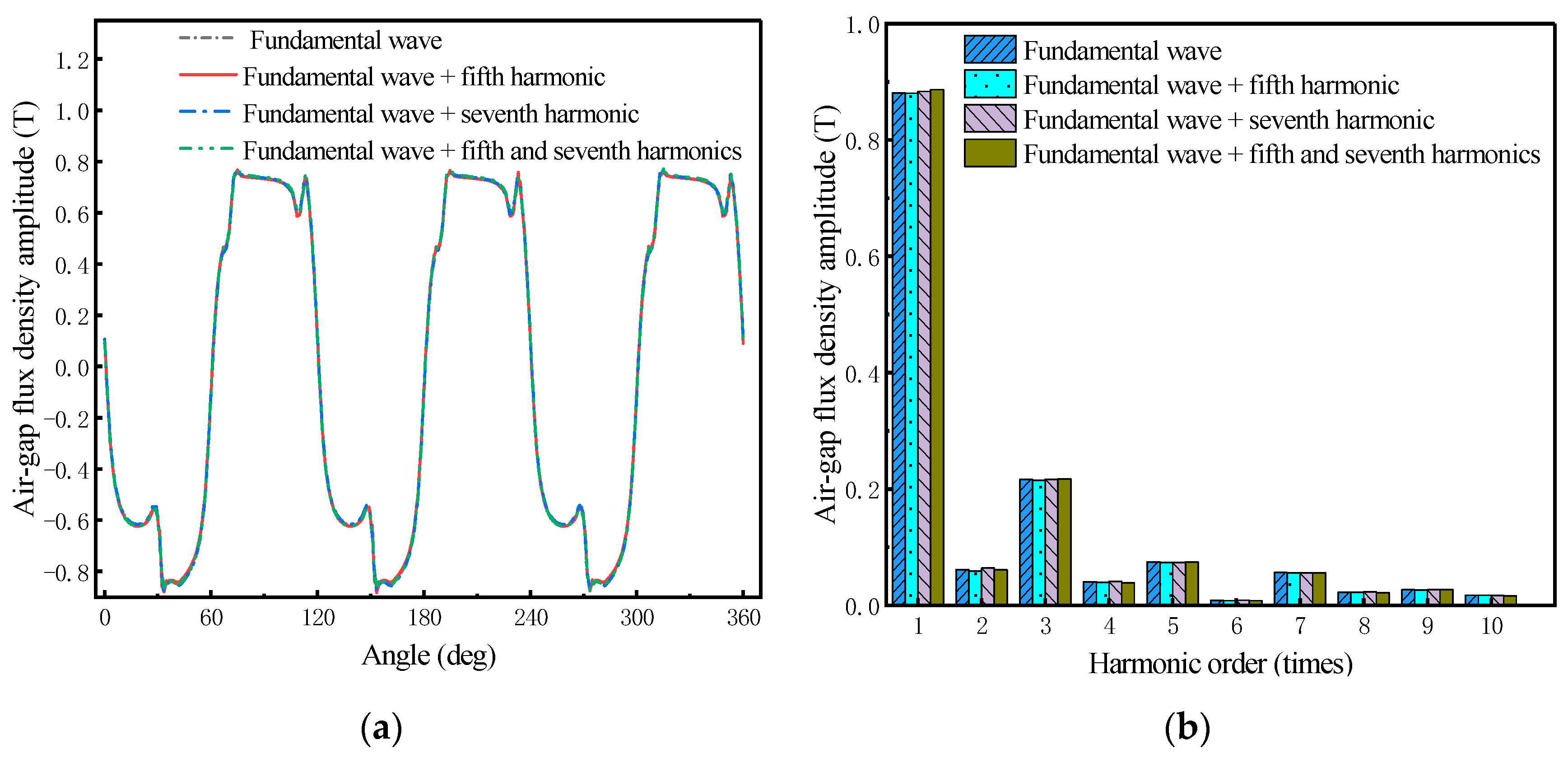
27]. To further analyze the impact of inverter harmonic currents on the electromagnetic field of permanent magnet shielded motors, the air-gap magnetic flux density waveforms and harmonic components of the stator windings under different excitation conditions were calculated, with the results shown in
Figure 5.
From
Figure 5, it can be observed that the time harmonics of the current cause an increase in the fundamental amplitude of the air-gap magnetic flux density. When the harmonic amplitude is 5% of the fundamental, the air-gap magnetic flux density fundamental wave amplitude with the presence of the fifth harmonic is the same as that under sinusoidal excitation, at 0.881 T. With the presence of the seventh harmonic, the air-gap magnetic flux density fundamental wave amplitude rises to 0.884 T, an increase of 0.34%. When both the fifth and seventh harmonics are present, the air-gap magnetic flux density fundamental wave amplitude rises to 0.887 T, an increase of 0.68%. From the results mentioned above, it can be seen that current harmonics are able to alter the fundamental wave amplitude of the air-gap magnetic flux density, thereby affecting the change in the motor’s leakage flux coefficient.
3.2. The Impact of Time-Harmonic Currents on the Leakage Flux Coefficient
Based on the aforementioned calculation results, the leakage flux coefficient of the permanent magnet shielded motor under different excitation conditions was subsequently calculated.
3.2.1. The Effect of the Order of Current Harmonics on the Leakage Flux Coefficient
First, the impact of the order of current time harmonics on the leakage flux coefficient was calculated and analyzed, with the results shown in
Figure 6.
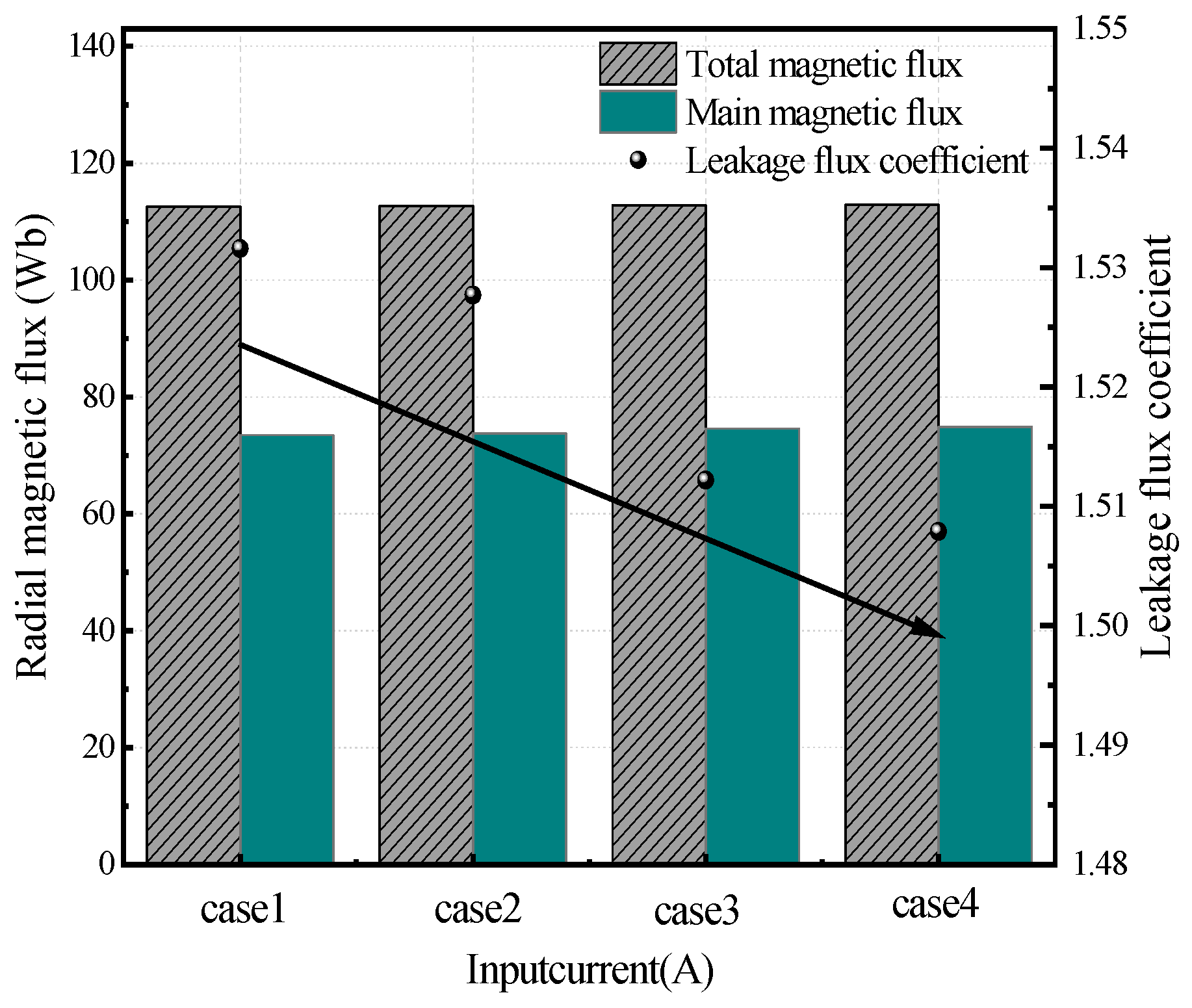
As can be seen from
Figure 6, when the motor is supplied with a sinusoidal current, the leakage flux coefficient is 1.531. When excited with a fifth harmonic having an amplitude of 5% of the fundamental, the leakage flux coefficient becomes 1.528, which represents a decrease of 0.20% compared to the sinusoidal supply. When excited with a seventh harmonic having an amplitude of 5% of the fundamental, the leakage flux coefficient is 1.512, which represents a decrease of 1.24% compared to the sinusoidal supply. When both the fifth and seventh harmonics are present, the leakage flux coefficient decreases to 1.508, marking a reduction of 1.50% compared to the sinusoidal supply. The decrease in the motor’s leakage flux coefficient under the non-sinusoidal supply may be due to the harmonic magnetic fields produced by the fifth and seventh time harmonics superimposing on the original fundamental wave magnetic field, altering its distribution and consequently reducing the motor’s magnetic flux leakage.
3.2.2. The Effect of the Harmonic Current Amplitude on the Leakage Flux Coefficient
Additionally, the influence of the current harmonic amplitude on the leakage flux coefficient was analyzed using the finite element method, with the results shown in
Figure 7. To simplify the legend in
Figure 7 and ensure its completeness, please refer to
Table 3 for the specific current excitation settings.
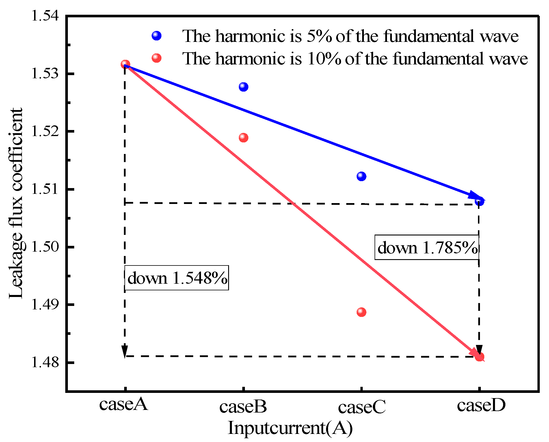
As can be seen from
Figure 7, the leakage flux coefficient decreases as the harmonic amplitude increases. When the motor is excited with fifth and seventh harmonics having an amplitude of 5% of the fundamental, the leakage flux coefficient is 1.508. When the amplitudes of the fifth and seventh harmonics are increased to 10% of the fundamental, the leakage flux coefficient decreases to 1.481, a reduction of 1.79%. This further verifies that the decrease in the motor’s leakage flux coefficient due to current time harmonics is caused by the superposition of harmonic magnetic fields, leading to reduced magnetic flux leakage in the motor.
3.3. The Effect of Rotor Position on the Leakage Flux Coefficient
Since the position of the motor’s rotor affects the distribution of the motor’s magnetic field, calculations and comparisons were made for the leakage flux coefficient at different rotor positions.
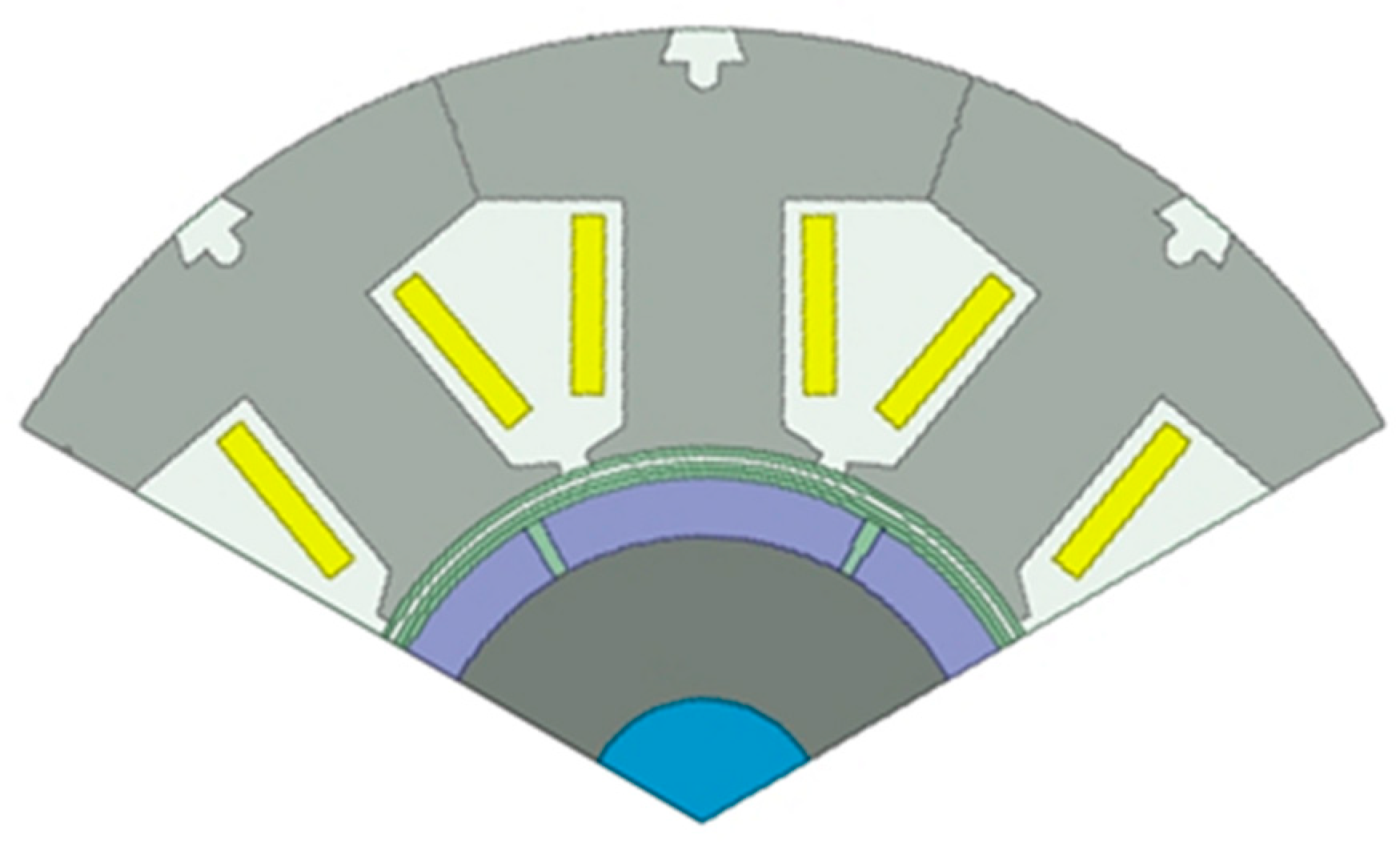
To reduce the computational load, a single motor unit was selected as the calculation model.
Figure 8 shows the calculation model of the 1.5 kW CPMSM’s unit motor.
During the calculation, it was set that when the axis of the permanent magnet coincides with the axis of the stator winding, the rotor angle is 0°. The leakage flux coefficient was calculated every 12° a total of 11 times. The calculation results of the leakage flux coefficient at different rotor positions are shown in
Table 4.
It can be seen from
Table 4 that when the motor rotor is in different positions, there are three scenarios for the size of the motor’s leakage flux coefficient, which are 1.55, 1.57, and 1.64, respectively. When the motor rotor angle is at 0°, 60°, and 120°, the motor’s leakage flux coefficient is the smallest, at 1.55. When the motor rotor angles are at 12°, 48°, 72°, and 108°, the motor’s leakage flux coefficient is the largest, at 1.64. As the rotor completes one electrical cycle, the average value of the leakage flux coefficient is 1.59, with deviations from the maximum and minimum values being 3.14% and 2.52%, respectively. These small deviations indicate that the average leakage flux coefficient can be used for magnetic circuit calculations.
4. Experimental Validation
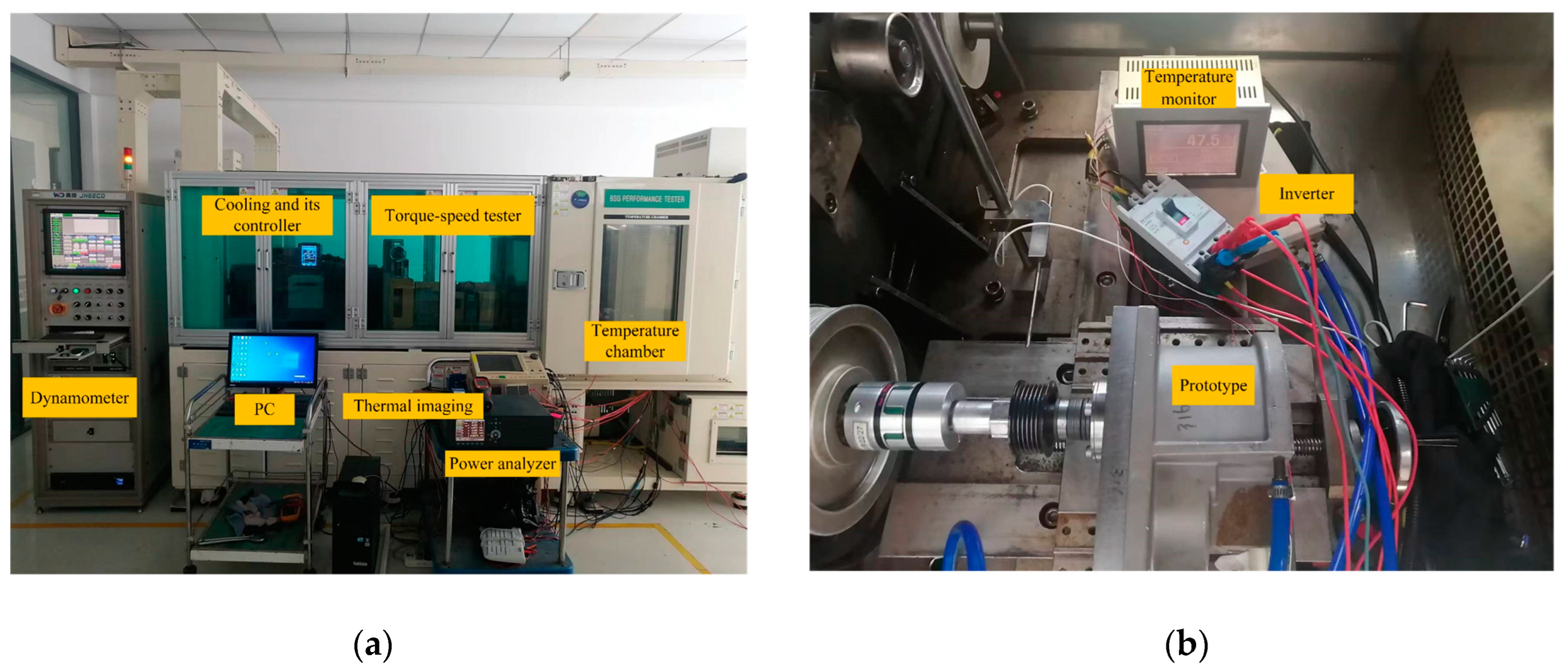
Therefore, to verify the accuracy of the calculation results in this paper, a prototype was manufactured based on the parameters and a prototype testing platform was set up.
Figure 9 shows the prototype testing platform. As shown in
Figure 9, the test platform consists of several components: the sample machine to be tested, the sample machine converter, the torque and speed tester, the dynamometer and its controller, water cooling equipment and its control unit, the adjustable temperature chamber, and measurement devices (power analyzer, oscilloscope, temperature monitor, thermal imager, etc.). The sample machine converter uses the high-performance vector converter AD800N series from Shenzhen Kewo (Shenzhen, China). The power analyzer is the NORMA5000 from Fluke (Cleveland, OH, USA), and the oscilloscope is the DL750 from Yokogawa (Tokyo, Japan).
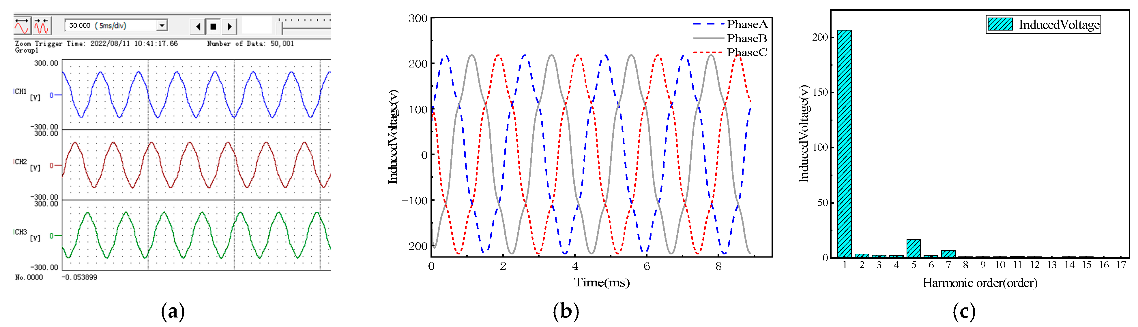
Using the motor test platform, the no-load back EMF of the prototype was measured using the back-to-back method. The measurement results were compared with the simulation results, as shown in
Figure 10.
As can be seen from
Figure 10, the back EMF waveform of the prototype shows good consistency with the simulation results. The measured no-load back EMF effective value of the prototype is 145.2 V, while the simulation calculated value is 147.2 V, with a difference of only 1.31%. This confirms the effectiveness and accuracy of the finite element calculation.
5. Conclusions
This paper studies the influence of time-harmonic currents from frequency converters on the motor’s leakage flux coefficient using a magnetic density integration method based on a finite element model of the motor. It also analyzes the impact of rotor positions on the leakage flux coefficient. The conclusions are summarized as follows:
(1) The motor’s leakage flux coefficient gradually decreases with the increase in the order and amplitude of the time-harmonic currents from the frequency converter, but the reduction magnitude is limited. Considering only the fifth and seventh harmonics with an amplitude of 10% of the fundamental wave, the motor’s leakage flux coefficient decreased by a maximum of 1.79%.
(2) The position of the motor rotor can have a certain impact on the leakage flux coefficient, with the maximum difference in the leakage flux coefficient at different positions being 5.81%.
This study delves into the impact of current harmonics on the leakage flux coefficient of permanent magnet shielded motors. Building on this, future research could focus on developing more efficient algorithms for the real-time monitoring and adjustment of current waveforms to minimize the effects of harmonics. Additionally, considering the variations in motor performance under different operating conditions, the study of the dynamic characteristics of harmonic effects under various load conditions is also significant.


