1. Introduction
As a highly maneuverable and flexible aircraft, quadrotor UAVs have been widely used in both civilian and military applications in recent years. Due to their complex nonlinear characteristics, multi-input and multi-output systems, and strong coupling, achieving precise attitude and position control has become a critical research topic [
1,
2,
3]. Common control methods include classical PID control [
4,
5,
6], Linear Quadratic Regulator (LQR) [
7,
8,
9], and fuzzy controllers [
10,
11,
12]. However, in complex external environments, such as wind disturbances and load variations, traditional control methods often fail to meet the high-precision control requirements. Therefore, an increasing number of studies are focusing on the design of more robust controllers.
Traditional UAV control methods typically adopt cascaded PID control [
13], where the outer loop controls the position via velocity control, and the inner loop controls attitude via angular velocity control. PID controllers are widely used due to their simple mathematical structure, ease of implementation and tuning, and their applicability to both linear and nonlinear systems without requiring a complex mathematical model. However, when there are significant variations in system parameters, PID controllers often face challenges such as instability or performance degradation. Additionally, PID tuning largely relies on manual experience, which is inefficient, especially in complex environments such as strong wind disturbances or significant load changes, where the traditional PID controllers’ disturbance rejection capability is insufficient, potentially leading to reduced control accuracy. Reference [
14] suggested using reinforcement learning to overcome the limitations of PID control, applying advanced machine learning algorithms to train the attitude control of quadrotors, yielding promising results. Additionally, Reference [
15] optimized PID parameters using Particle Swarm Optimization (PSO), using IAE, ISE, ITAE, and ITSE as performance evaluation criteria. The results show that PSO-PID controllers outperform traditional PID controllers during wind disturbances.
To enhance flight control performance, References [
16,
17] proposed the use of Active Disturbance Rejection Control (ADRC) in quadrotor systems. ADRC, introduced by Chinese scholar Han Jingqing [
18], is a modern control technique that aims to achieve effective control for systems with complexity, uncertainties, and strong disturbances. It works by estimating and compensating for internal and external disturbances in real time, ensuring precise control even in systems with significant uncertainties. The core idea is to treat both internal uncertainties and external disturbances as a generalized disturbance, which is dynamically estimated and compensated in real time through an Extended State Observer (ESO). ADRC is known for its robustness, real-time disturbance compensation, and not requiring precise modeling. However, it involves many parameters, and tuning is often manual, making it challenging to achieve optimal performance. Professor Gao Zhiqiang proposed a Linear Active Disturbance Rejection Controller (LADRC) [
19], which retains the robustness and disturbance rejection capabilities of ADRC while simplifying the design of the observer and control law, addressing the tuning challenges posed by traditional ADRC in practical applications. References [
20,
21] applied LADRC to quadrotor UAVs, demonstrating its ability to estimate and compensate for disturbances effectively. In Reference [
22], a fuzzy control-based linear active disturbance rejection controller (LADRC) was proposed. Compared to traditional active disturbance rejection controllers, the linear active disturbance rejection controller achieves linear compensation for uncertain disturbances and requires fewer parameters to be adjusted. The simulation results show that, compared with traditional PID control, the attitude controller using F-LADRC can effectively reduce uncertain disturbances and exhibits strong robustness, making it suitable for scenarios with aerodynamic uncertainties and gust disturbances during flight. Reference [
23] employed an improved sparrow search algorithm combined with an active disturbance rejection controller to enhance the disturbance rejection capability of a quadrotor UAV. This approach addresses the significant degradation in attitude control accuracy and stability caused by parameter uncertainties and external disturbances. The improved sparrow algorithm optimizes LADRC parameters, avoiding the issue of falling into local optima.
In recent years, neural networks have been increasingly applied in the design of controllers. Neural networks can handle nonlinearity and uncertainty through adaptive learning, enhancing the stability and control accuracy of UAVs. Reference [
24] utilized neural networks to build control schemes for quadrotors, introducing a neural network observer to estimate various states of the UAV, and proposing output feedback control laws to improve robustness. Reference [
25] proposed a cascade Fuzzy Neural Network (FNN) for position control of a quadrotor UAV, where the attitude loop adopts offline learning, and the position loop adopts online learning to reduce the computational load of FNN and accelerate the system’s response speed, showing good performance in position control. In Reference [
26], a Spiking Neural Network (SNN) was utilized to control a quadrotor UAV. Sliding mode control theory was employed to ensure the stability of system responses, and online learning was used to enhance the system’s robustness. Simulation results show that using an SNN offers strong system response capabilities. Reference [
27] introduced the use of a Backpropagation Neural Network (BPNN) and an Adaptive Linear Active Disturbance Rejection Controller (ALADRC) as the attitude control system for a quadrotor UAV. A dynamic model for a variable-mass quadrotor UAV was established to introduce the load variable, and the simulation results demonstrated that the designed mass-adaptive control law effectively mitigates the adverse effects of load changes compared to LADRC and DSADRC controllers. Reference [
28] proposed using a Deep Q-Network (DQN) to automatically adjust PID parameters, achieving precise control strategies under given expected inputs. This controller was utilized to optimize the issue of UAVs significantly deviating from their flight path during landing due to external disturbances. The results indicated that the DQN-optimized PID controller exhibited superior convergence and maneuverability compared to traditional PID controllers.
Sliding Mode Control (SMC) is a nonlinear control method based on variable structure control theory, suitable for systems with strong nonlinearity, uncertainty, and disturbances. SMC achieves the desired control objectives by designing a sliding mode surface and switching control laws, allowing the system states to slide along the sliding mode surface. Reference [
29] proposed an adaptive PID controller based on SMC for precise control of the position and attitude of a quadrotor UAV. This method automatically adjusts the PID parameters using second-order sliding mode control and employs a fuzzy compensator to reduce UAV jitter. The simulation results demonstrated good performance, and experimental validation confirmed that this controller could produce better transient performance and quickly converge. Reference [
30] introduced a Fast Terminal Sliding Mode Controller (FTSMC) to achieve trajectory tracking for UAVs. Additionally, a finite-time Nonlinear Disturbance Observer (NDO) was proposed to estimate external disturbances affecting the height and attitude channels of the UAVs. Simulation and experimental results verified the robustness and effectiveness of the proposed control method, demonstrating its ability to bring tracking errors to zero in finite time. Reference [
31] presented a Proportional-Derivative Sliding Mode Control (RPD-SMC) method based on Adaptive Radial Basis Function Neural Networks (RBFNNs). Furthermore, a Robust Integral of the Sign of the Error (RISE) method was applied in the inner loop to enhance robustness. Stability theory was utilized to prove the steady-state tracking capability of this controller, and simulations validated the effectiveness of the proposed control strategy. Reference [
32] proposed a Model-Free Single-Dimensional Fuzzy Sliding Mode Control (MFSDF-SMC) algorithm to address the underactuated, nonlinear, and model-uncertain characteristics of quadrotor UAVs. The simulation results indicated that this algorithm possesses strong robustness, enabling the quadrotor UAV to quickly regain stability under significant disturbances.
In this paper, to improve parameter tuning efficiency and achieve optimal parameter settings, a nested inner–outer loop model is developed based on a quadrotor UAV model. The outer loop, responsible for position control, uses a PID controller optimized by a Genetic Algorithm-based Particle Swarm Optimization (GA-PSO), where GA performs global optimization and PSO fine-tunes the optimal parameters found by GA. The inner loop, responsible for attitude control, adopts a fuzzy adaptive LADRC, where the fuzzy algorithm adjusts the LADRC parameters in real time. Simulation experiments compare the proposed controller with traditional cascaded dual-loop PID, an outer-loop PID with an inner-loop LADRC, and an outer-loop PID with a fuzzy adaptive LADRC (Fuzzy-LADRC). The results confirm that the proposed control algorithm achieves excellent control performance and disturbance rejection, allowing stable tracking of input signals.
2. Quadrotor Modeling
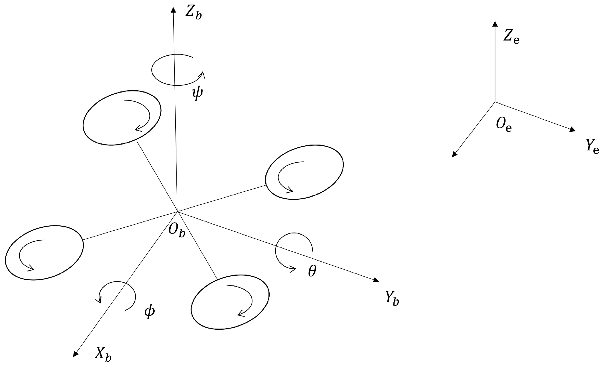
In this paper, an X-type quadrotor configuration is adopted, as shown in
Figure 1. The body coordinate system
of the quadrotor UAV is established. It is assumed that the quadrotor UAV is a rigid body structure with its center of gravity coinciding with the geometric center. The origin
of the body coordinate system is located at the UAV’s center of gravity. The
-axis points to the front of the UAV, the
-axis points to the left, and the
-axis is perpendicular to the
plane and points upwards. The Earth frame is denoted as
, and the position
and attitude angles
of the UAV are described using both the body coordinate system and the Earth coordinate system.
Determining the position and attitude of the UAV in the air requires the conversion of the airframe coordinate system to the geodetic coordinate system. The rotation matrix for the conversion from the airframe coordinate system to the geodetic coordinate system is
where
and
are
and
, respectively. Using Newton’s and Euler’s laws of motion, the following equations of kinematics for a quadrotor UAV can be obtained:
where
represents the total weight of the quadrotor UAV;
represent the moments of inertia of the quadrotor UAV around
, respectively;
is the total thrust generated by the quadrotor UAV;
represent the control inputs around
, respectively;
represents the gravitational acceleration;
is the distance from the center of gravity of the quadrotor UAV to the center of the rotor;
are the aerodynamic drag coefficients for translational motion in the three directions, respectively;
represent the aerodynamic drag coefficients for rotational motion around the three axes;
are the external wind forces acting along the three axes;
are the disturbance torques generated by the wind field around the three axes.
The system control inputs
,
for the quadrotor UAV are related to the rotational speeds
of the four rotor motors as follows:
where
is the thrust coefficient, and
is the counter-torque coefficient.
3. Controller Design
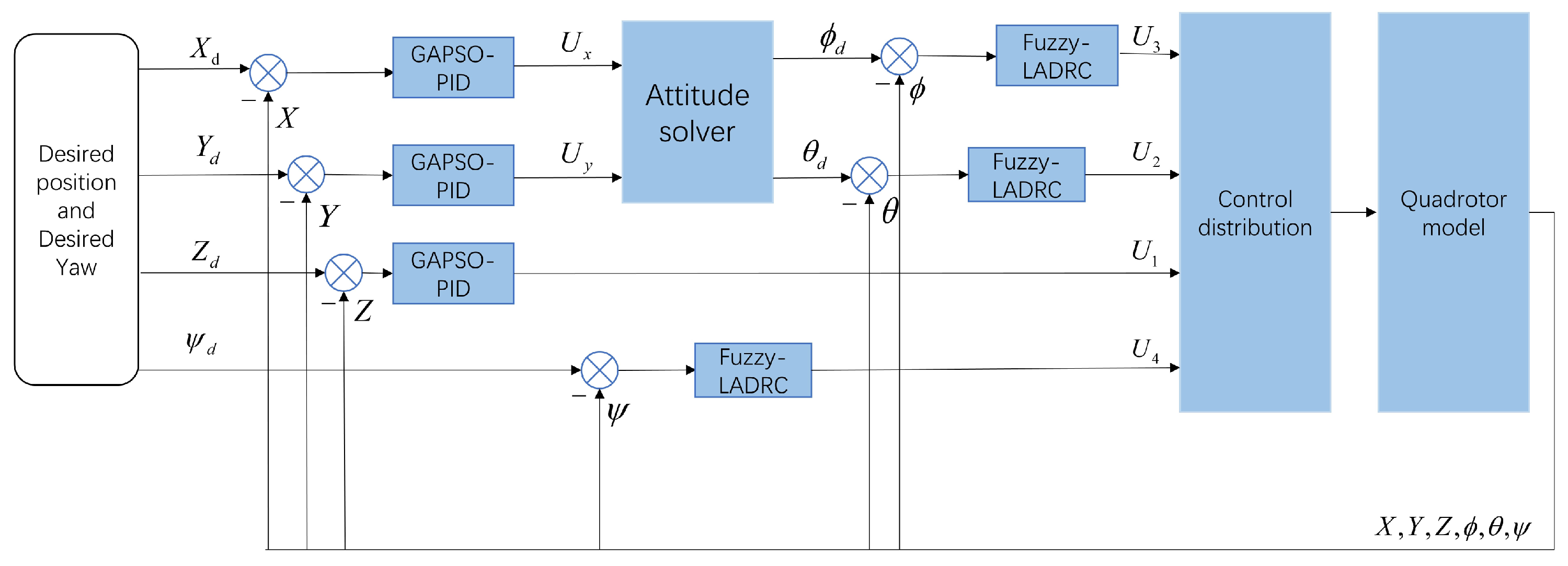
Considering the strong coupling, nonlinearity, and underactuated characteristics of the quadrotor UAV system, a novel inner–outer loop nested control structure is designed. The outer loop (position control) adopts a cascaded PID controller optimized by Genetic Algorithm-based Particle Swarm Optimization (GA-PSO), while the inner loop (attitude control) uses a second-order Linear Active Disturbance Rejection Controller (LADRC) with fuzzy control, as shown in
Figure 2. In the position loop, the PID parameters are manually coarsely tuned, followed by global optimization using a genetic algorithm, and finally, fine-tuned using particle swarm optimization within a smaller range to obtain the optimal PID parameters for the position loop. In the attitude loop, fuzzy control dynamically adjusts the LADRC parameters in real time to achieve optimal control.
Where
are the control outputs of the position loop along the
axes, respectively. The desired roll angle
and pitch angle
are obtained through the attitude resolver, and the calculation formulas are as follows:
3.1. Attitude Control
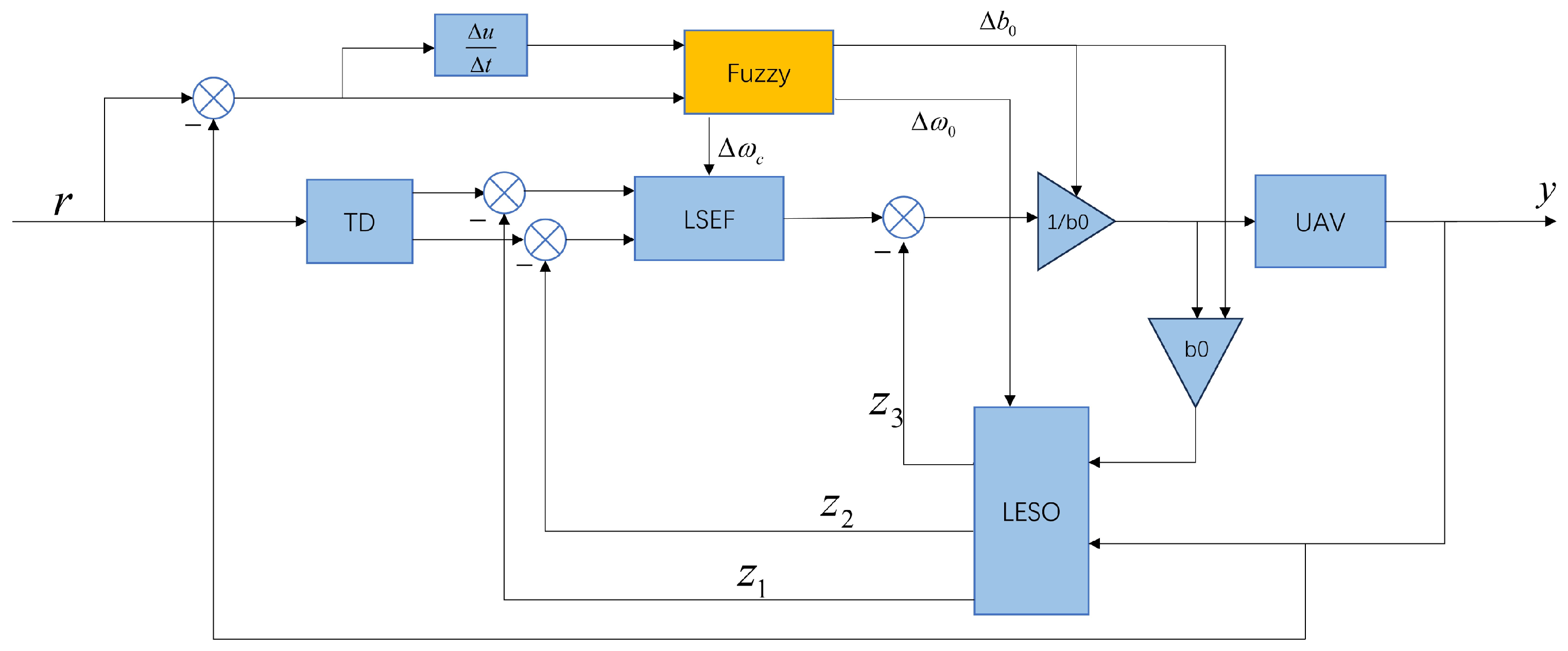
The attitude controller designed in this paper is an adaptive second-order Linear Active Disturbance Rejection Controller (LADRC) based on fuzzy control, as shown in
Figure 3. Compared to the traditional LADRC controller, a fuzzy controller is added to adjust the relevant parameters of LADRC in real time to handle external uncertainties and disturbances. The LADRC controller consists of a Tracking Differentiator (TD), a Linear Extended State Observer (LESO), and a Linear State Error Feedback Control Law (LSEF).
Large initial errors are avoided by feeding the desired signal to the tracking differentiator to obtain two signals, one for the transition at the tracking point and one for differentiating the transition at the tracking point.
where
is the input target signal;
are the transition signal and the derivative of the transition signal, respectively; and
is the tracking factor that determines the speed of the tracking response.
LESO estimates both the system’s state variables and the total disturbance. This is achieved by continuously updating estimates of the system states and disturbances based on system output measurements. Since this system is second-order, its dynamic model can be represented as
where
is the system output,
is the control input,
is the controller gain,
represents the system state variables, and
denotes external disturbances. By combining the system state and external disturbance, we define a total disturbance term:
Thus, the dynamic model can be expressed as
To design the LESO, we define the extended system state variable as follows:
The state-space equations of the system can be formulated as follows:
Under the assumption that the total disturbance changes slowly, we can approximate as a constant.
To observe
, a linear extended observer is constructed to estimate them:
where
is the estimated value of the system state
, and
is the estimated total disturbance.
represent the observer gain, and
, where
is the observer bandwidth, and
is the compensation factor.
The formula for the controller is
where
is the total control of the LADRC controller.
The Linear State Error Feedback (LSEF) combines the transition signal and its derivative generated by the Tracking Differentiator (TD) with the system states estimated by the Linear Extended State Observer (LESO) through a PD controller to obtain the virtual control input
.
where
is the virtual control input calculated by the LSEF. The controller gains are
and
, and
is the controller coefficient.
The design of the LADRC controller is completed through the above steps, followed by the incorporation of fuzzy control.
The performance of the LADRC depends on the selection of observer gains and controller gains; however, these gains are often difficult to manually adjust during system operation, especially when dealing with complex nonlinear systems or uncertainties in the external environment. In this case, implementing adaptive adjustment of the gains through fuzzy control can enhance the dynamic performance and robustness of the system. The difference between the desired and actual values, along with its derivative, is used as the input for the fuzzy control. Membership functions are set, and fuzzy rules are formulated to output
to various modules through the process of fuzzification, fuzzy reasoning, and defuzzification, thereby achieving adaptive adjustment of the control parameters of the system.
In the equation,
are the initialization parameters obtained through empirical tuning, and
are the output of the fuzzy control.
In this paper, “trimf” is chosen for the input and output membership functions. The fuzzy rules for
are presented in
Table 1,
Table 2 and
Table 3.
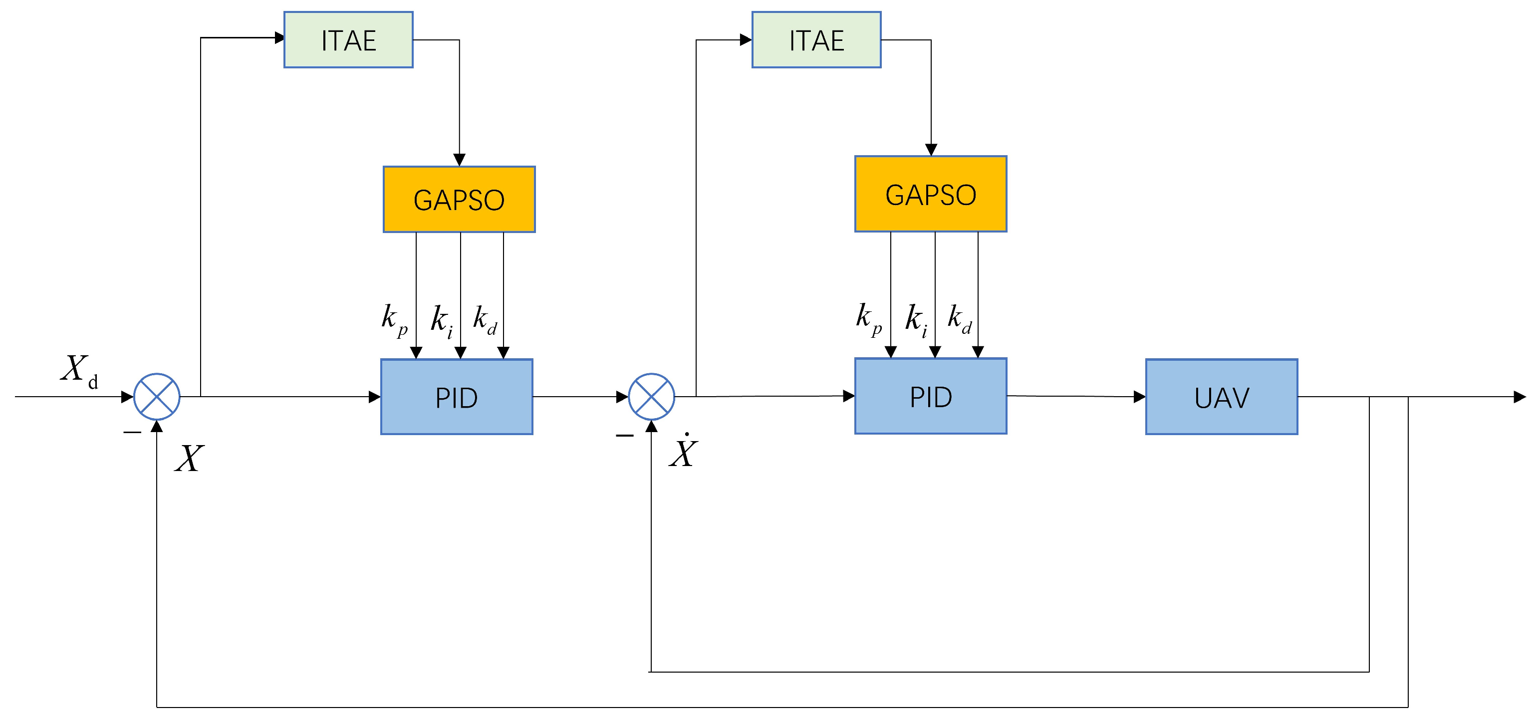
3.2. Position Control
The position loop controller designed in this paper is shown in
Figure 4. This controller is based on the traditional cascaded PID controller, utilizing a genetic algorithm for broader optimization and then combining it with particle swarm optimization to perform fine-tuning around the optimized parameters obtained from the genetic algorithm to achieve the optimal PID parameters.
The PID controller consists of three components: proportional control
, integral control
, and derivative control
. The proportional component serves to control the system by bringing the feedback value closer to the target value; the integral component eliminates steady-state error; and the derivative component generates a damping effect to suppress oscillations and overshoot. The formulas are as follows:
However, traditional PID control parameters are often tuned based on manual experience, which is time-consuming and labor-intensive, and the results may not necessarily achieve optimal performance. To address this issue, this paper proposes a method that combines Genetic Algorithm (GA) and Particle Swarm Optimization (PSO) to find optimal parameters.
Particle Swarm Optimization (PSO) is an optimization algorithm based on swarm intelligence, introduced by Kennedy and Eberhart in 1995. PSO is inspired by the foraging behavior of bird flocks or fish schools in nature and employs a simple mechanism to guide the particle swarm toward the optimal solution. The core idea of PSO is to iteratively approach the optimal solution through the cooperation and competition among individual particles in the swarm.
PSO generates a group of particles randomly, where each particle
represents a potential solution with an initial velocity
and position
. The particles search for the optimal solution by updating their velocity and position. The formulas for updating velocity and position are as follows:
where
represents the velocity information of the
particle in the
iteration,
represents the position information of the
particle in the
iteration,
is the inertia weight,
and
are the learning factors,
and
are random numbers,
is the historical optimal position of the
particle, and
is the historical optimal position of the entire particle swarm.
To evaluate the quality of the obtained values, a fitness function, specifically the Integral of Time-weighted Absolute Error (ITAE), is introduced. The ITAE reflects multiple aspects of the controller’s performance, including the system’s regulation speed, overshoot, and error. Its defining formula is as follows:
where
represents time, and
represents the error.
When new position information is obtained, the particles will be evaluated based on the fitness function, and the updates for
and
are performed according to the following formulas:
The Genetic Algorithm (GA) is an optimization algorithm that mimics the biological evolution process found in nature, proposed by John Holland in 1975. GA is based on mechanisms such as selection, crossover, and mutation in biological evolution, simulating the process of populations searching for optimal solutions through generations of evolution.
While PSO excels in local search, GA possesses strong global search capabilities. Combining the two allows the optimization process to perform global exploration to avoid local optima while fully utilizing PSO’s rapid convergence characteristics in local search, thereby improving the efficiency and accuracy of the algorithm. The diversity in GA makes it less likely for the algorithm to become trapped in local optima, while PSO’s quick convergence capability can accelerate the convergence when the population approaches the optimal solution. The combination of both maintains the diversity of the solution space while enhancing the algorithm’s convergence speed. The population evolution of GA and the collaborative nature of PSO can be integrated to diversify the information transmission mechanism, thus improving the overall performance of the swarm. GA is responsible for long-term exploration, while PSO focuses on short-term exploitation, enhancing both the depth and breadth of exploration. By introducing randomness through GA’s mutation operation, the exploration capability of the solution space is strengthened, preventing PSO from prematurely converging on local optima. The integration of GA’s mutation mechanism can increase the diversity of the PSO population, assisting the algorithm in escaping local optimal solutions.
The steps for combining GA and PSO are as follows:
Randomly generate a population of size NNN, where each individual represents a potential solution. Calculate the fitness of each individual in the population as a measure of quality.
Select parent individuals based on their fitness. Perform crossover on the selected parents to generate new individuals, and apply random mutation operations to some individuals to increase population diversity and avoid premature convergence to local optima.
Calculate the fitness of the newly generated individuals. If their fitness is higher, replace the parent individuals; otherwise, retain the parents. Repeat the processes of selection, crossover, mutation, fitness evaluation, and population updating until the maximum number of iterations or fitness threshold is reached.
Use the final individuals of the GA population as the initial solutions for PSO, laying the foundation for local search. The initial velocity and position of each individual are set to the optimized results from GA.
In this phase, update the velocity and position of the particles based on the GA optimization results. Evaluate the fitness of each particle’s new position. If the new position is better than the individual particle’s best position, update the individual best position; if it is better than the global best position of all particles, update the global best position.
Repeat the processes of velocity updating, position updating, and fitness evaluation until the maximum number of iterations or fitness threshold is reached. Finally, output the optimal solution obtained from the GA-PSO combination.
Through these steps, the optimal parameters for PID control can be determined and integrated into the PID controller module.
The parameter settings for the GA-PSO algorithm are shown in
Table 4, and the variation of the fitness function with respect to the number of iterations is illustrated in
Figure 5.
The total number of iterations for the Genetic Algorithm (GA) and Particle Swarm Optimization (PSO) was set to 150. From the fitness function’s variation graph, it can be observed that during the GA optimization—particularly in the initial 50 iterations—there are significant changes in the fitness function, with the most notable variations occurring within the first 20 iterations. This indicates that the GA effectively performs extensive global optimization. During the subsequent 100 PSO iterations, the fitness function curve shows a gradual change, achieving stability around the 80th iteration. This suggests that PSO successfully refines the parameters, initially optimized by GA, to reach even lower ITAE values, confirming that the derived parameters are optimal for this scenario.
4. Simulation and Discussion
The newly designed controller in this paper is compared with the traditional double closed-loop cascade PID controller, the external traditional PID and internal linear active disturbance rejection controller, and the external traditional PID with the internal fuzzy adaptive adjustment controller, hereinafter referred to as GAPSOPID-FuzzyLADRC, PID-PID, PID-LADRC, and PID-FuzzyLADRC. All four controllers are integrated into the same quadrotor UAV model. By inputting the same expected signals and disturbance signals, the control performance and disturbance resistance of each controller are demonstrated.
The relevant parameters of the quadrotor UAV are shown in
Table 5. The initial state controller parameters for each channel are shown in
Table 6 and
Table 7.
4.1. Tracking Signal Simulation
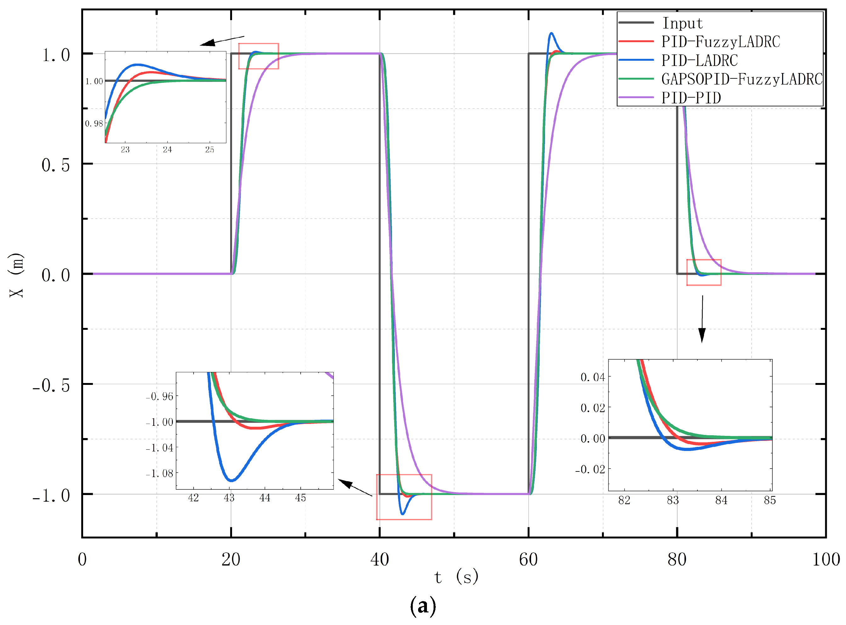
The initial position of the quadrotor UAV is set at (0, 0, 0), with the initial attitude angles being (0, 0, 0). The specified flight trajectory for the quadrotor UAV is shown in
Table 8. The simulation results of the position tracking signals are illustrated in
Figure 6, while the simulation results of the signal tracking errors are depicted in
Figure 7.
From
Figure 6, it can be observed that when tracking the X position from 0 to 1 m, the GAPSOPID-FuzzyLADRC controller can track the trajectory within 4.25 s, whereas the PID-LADRC, PID-FuzzyLADRC, and PID-PID controllers require 5.45 s, 5.25 s, and 11.26 s, respectively, to stabilize and track the trajectory. Additionally, the overshoot amounts for the PID-LADRC and PID-FuzzyLADRC are 0.65% and 0.42%, respectively.
When tracking the X position from 1 to −1 m, the GAPSOPID-FuzzyLADRC controller achieves trajectory tracking within 4.41 s, while the PID-LADRC, PID-FuzzyLADRC, and PID-PID controllers take 5.52 s, 5.62 s, and 14.32 s, respectively, to stabilize and track the trajectory. Furthermore, the overshoot amounts for the PID-LADRC and PID-FuzzyLADRC are 9.36% and 1.45%, respectively.
For the Z position tracking from 0 to 1 m, the GAPSOPID-FuzzyLADRC controller tracks the trajectory in 1.55 s, while the PID-LADRC, PID-FuzzyLADRC, and PID-PID controllers take 1.62 s, 1.61 s, and 2.45 s, respectively, to stabilize and track the trajectory. The overshoot amounts for the PID-LADRC, PID-FuzzyLADRC, and GAPSOPID-FuzzyLADRC are 3.65%, 1.67%, and 1.42%, respectively. When tracking the Z position from 1 to 0 m, the GA-PSO-PID-FuzzyLADRC controller tracks the trajectory within 1.46 s, while the PID-LADRC, PID-FuzzyLADRC, and PID-PID controllers require 1.74 s, 1.68 s, and 2.54 s, respectively, to stabilize and track the trajectory. The overshoot amounts for the PID-LADRC and PID-FuzzyLADRC are 0.36% and 0.11%, respectively.
To facilitate analysis, the ITAE is used as the evaluation metric for the controllers, as shown in
Table 9. The table indicates that the GAPSOPID-FuzzyLADRC has a smaller ITAE value.
Through the comparison of the four control algorithms, it can be concluded that the proposed GAPSOPID-FuzzyLADRC exhibits faster convergence speed and smaller overshoot.
4.2. Tracking Signal Simulation with External Disturbances Introduced
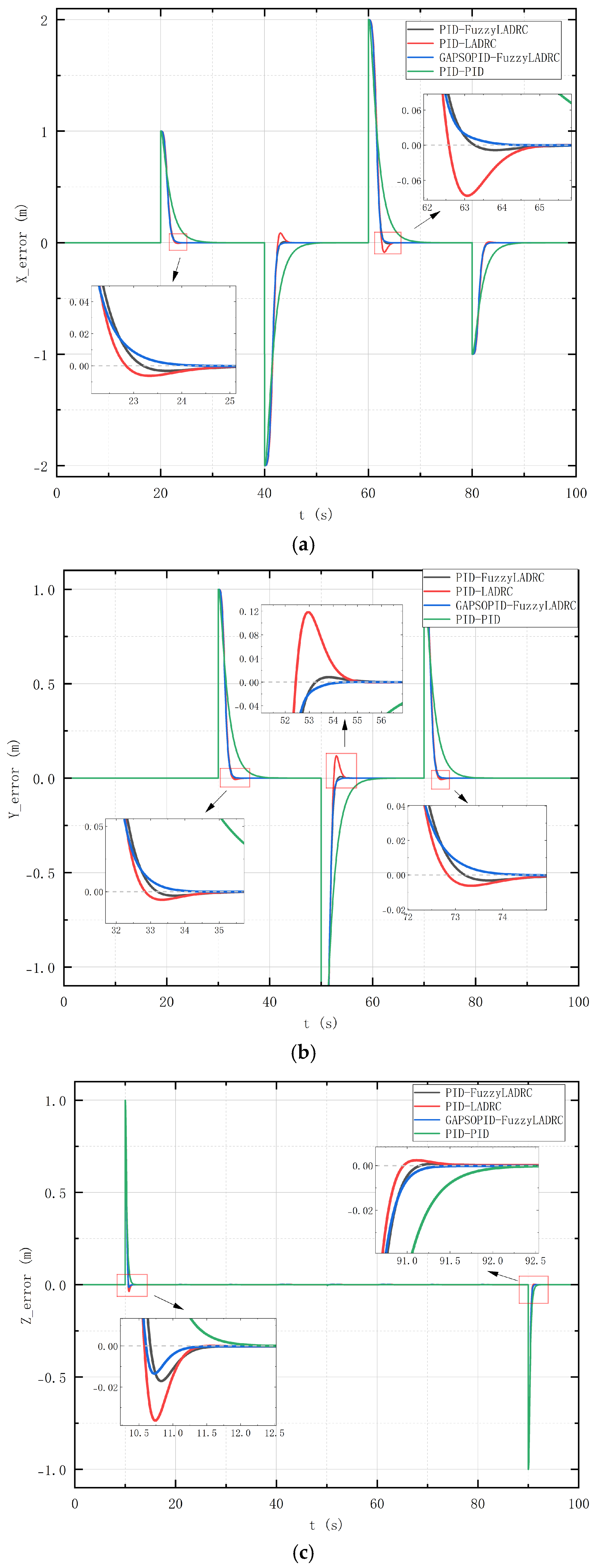
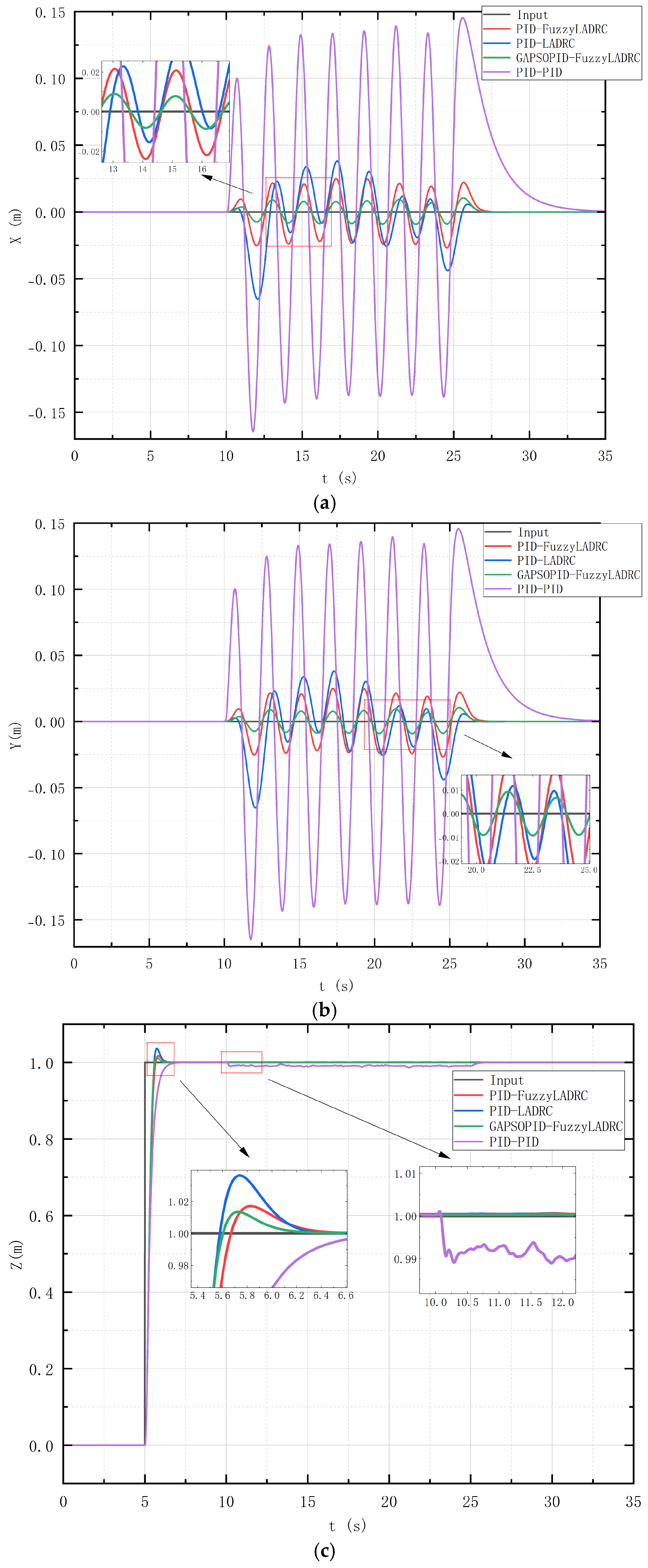
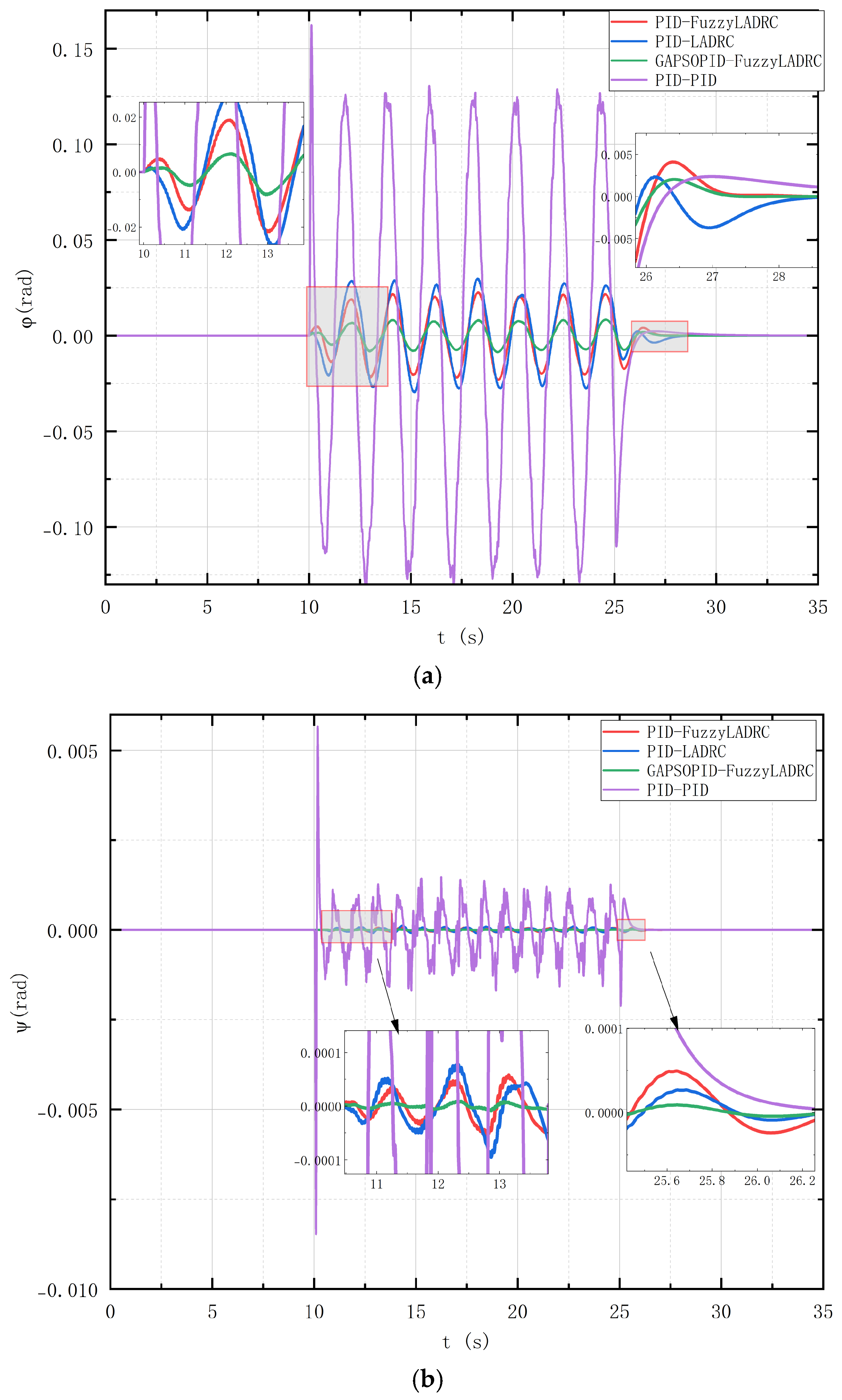
The initial position of the quadrotor UAV is set at (0, 0, 0), with an initial attitude angle of (0, 0, 0). The quadrotor remains stationary at this initial position for 5 s before moving to (0, 0, 1) and maintaining this position. At 10 s, a time-varying wind with Gaussian white noise is introduced, as shown in
Figure 8. The simulation results of the position tracking signal are illustrated in
Figure 9, and the simulation results for attitude signal tracking are shown in
Figure 10.
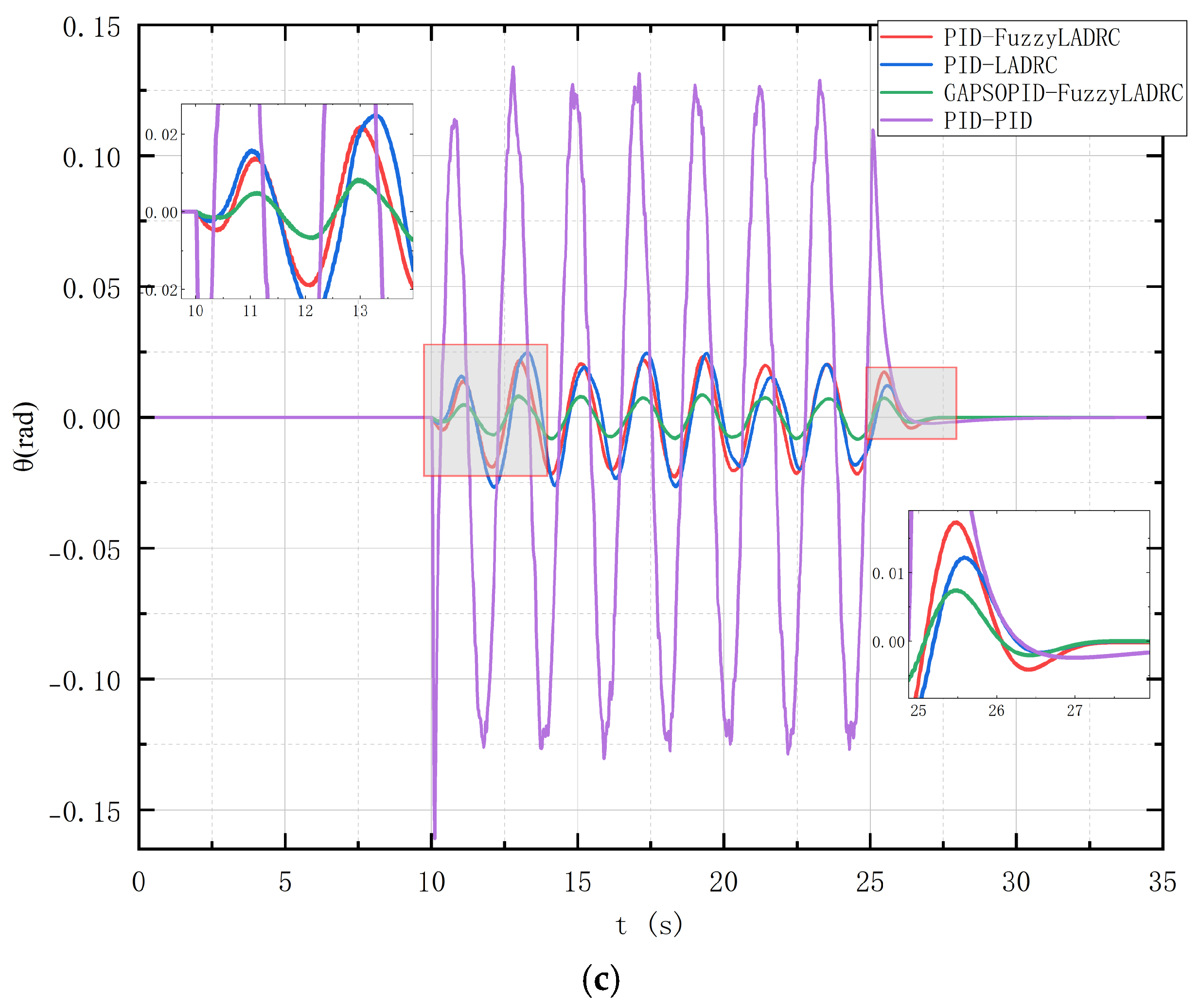
Table 10 presents the ITAE values for each channel. It can be observed that the proposed GAPSOPID-FuzzyLADRC controller exhibits smaller ITAE values, indicating stronger stability and robustness.
From
Figure 9 and
Figure 10, it is evident that the LADRC controller demonstrates significantly better disturbance rejection capabilities compared to the traditional PID controller. The traditional PID controller has much larger overshoot and longer time to stabilize compared to the LADRC controller. Among them, the proposed GAPSOPID-FuzzyLADRC controller shows superior disturbance rejection capability, smaller overshoot, and faster stabilization time compared to both PID-LADRC and PID-FuzzyLADRC controllers.


