1. Introduction
Lower urinary tract dysfunction (LUTD) refers to the dysfunction of the bladder and urethra that exists during the voiding or storage phase. A survey in five European and American countries showed that the prevalence of LUTD is about 64.8% [
1]. Invasive surgical treatments such as sacral neuromodulation are the most effective treatments for LUTD symptoms and are widely used in the clinic [
2,
3]. Sacral neuromodulation (SNM) refers to the implantation of electrodes to apply low-frequency electrical impulses to specific sacral nerves. It is used to treat some LUTD and pelvic floor dysfunction diseases [
4].
SNM stimulators need to be turned on so that they can stimulate nerves every day. But most existing SNM stimulators are powered by disposable batteries. Surgery is required to replace the stimulator when the power runs out, which is a major inconvenience for the patient. The expected battery life of the InterStim
TM II system (Medtronic, Minneapolis, MN, USA) is 5 years. However, Siegel found that 36 months after implantation, 11% of patients need to replace the stimulators [
5]. Therefore, it is necessary to introduce wireless power transferring (WPT) into implantable sacral nerve stimulators.
Currently, there are many WPT applications in implantable electronic devices. Wang [
6] developed an artificial retina power supply device based on the Class-E structure with an operating frequency of 1 MHz and a power-transferring capability of 250 mW. However, when the distance between the transmitter and receiver was 15 mm, the maximum transmission efficiency was only 38.5%. Watada [
7] developed a wireless power supply system for a left ventricular assist device with an operating frequency of 60 to 120 kHz and a power transfer efficiency of 40%. Lee [
8] developed a wireless head-mounted deep brain stimulator using a new adaptive rectifier to achieve AC–DC power conversion. With an operating frequency of 2 MHz and a distance of 15 mm between the transmitter and the receiver, the transmission efficiency of the system reached 58–68%.
But these wireless power transfer systems in implanted electronics are not suitable for SNM stimulators. These wireless power transfer systems have short charging distances and low transfer efficiencies. Moreover, the receiver coil needs to be as small as possible to minimize the foreign body sensation when being implanted. Therefore, it is necessary to develop new WPT system technology with higher wireless charging efficiency and longer transmission distance.
Existing sacral nerve stimulator, such as the InterStim
TM II system, is large in size and is made of hard materials that make patients experience a foreign body sensation during use [
9]. SNM devices need to be left in the patient’s body for a long period of time; therefore, a patient’s comfort with the implanted stimulator is an important factor affecting the patient’s quality of life. Also, due to a lack of mechanical fixation, the stimulator is prone to shift when the patient’s body moves, causing coils in the WPT system to fail in aligning with each other and making charging even more inefficient. Therefore, wireless power transmission through 15 mm fat–skin tissue in the buttocks will be weakened greatly, and the constant current required to keep the stimulator working will not be maintained.
To improve the transmission efficiency, the WPT system based on the parity–time (PT) symmetry theory has been explored to achieve a higher level of charging efficiency in the PT-symmetric region even when the transmitter and receiver are far apart, and their centers are slightly misaligned. Fan used a circuit based on PT symmetry condition to ensure a constant payload impedance on the switched-mode amplifier even if the transmission distance changed. With this approach, robust wireless energy transfer could work in the PT-symmetric strong coupling region, allowing the WPT system to have a 10 W output power and an up to 92% transmission efficiency when the transmission distance changes from 0 to 65 cm [
10]. Zhou [
11] proposed a nonlinear PT-symmetric model for constant-efficiency WPT applications for unmanned aerial vehicles in flight. This approach allowed flexibility in designing the output power by adjusting voltage of the DC supply without the limitation of the saturation voltage of the operational amplifier. However, the coils used in these systems for energy transmission were very large, exceeding 60 cm in diameter; thus, they are not suitable for the wireless charging of SNM stimulators.
In this paper, a flexible wireless sacral nerve stimulator based on parity–time symmetry condition is proposed. We optimize the coil structure using electromagnetic field simulation and improve the distance, efficiency, and stability of wireless charging by introducing the PT symmetry theory. The system can not only achieve efficient wireless charging across 2 cm skin thickness but also increase the stability of wireless charging when the stimulator is shifted due to human movement. A flexible electronic system is designed to achieve the flexibility of the coils and the whole SNM stimulator, which can solve the problem of the foreign body sensation during the patient’s use. Experiments have been conducted to verify the reliable operation of the stimulator.
2. Materials and Methods
2.1. Working Mode Analysis
The basic circuit of the wireless power transfer system based on the PT symmetry is shown in
Figure 1, where
represent the capacitances of the transmitter and receiver;
represent the inductances of the transmitter and receiver coils;
represent the equivalent resistances of the transmitter and receiver coils;
represent the voltages of the transmitter and receiver;
represent the currents of the transmitter and receiver coils;
is the negative resistance on the transmitter side, which is used as a gain source;
is the load resistance on the receiver side; and M is the mutual inductance. We analyze the PT symmetry of this basic circuit based on the circuit theory.
According to Kirchhoff’s voltage law, the circuit can be described as follows:
Taking
,
, Equation (1) can be rewritten as follows:
Because of the existence of non-zero solutions, the value of the determinant of the coefficient matrix must be zero. The separation of the real and imaginary parts can obtained as follows:
According to (3), the eigenfrequencies can be described as follows:
where critical coupling coefficient,
,
.
In the strong coupling region,
,
, Equation (3) is known as the following:
By substituting Equation (5) into Equation (2), the current distribution obtained is as follows:
And the phase difference between currents is as follows:
Power transfer efficiency and output power are as follows:
In the weak coupling region,
,
, power transfer efficiency and output power are as follows:
In the strong coupling region, when the system is in the PT-symmetric state, the transmission efficiency of the system does not vary with the coupling coefficient. In the weak coupling region where the system is in the PT-broken state, the system efficiency is no longer constant, but becomes lower due to the decrease in the coupling coefficient. Therefore, as long as the WPT system works in the PT-symmetric strong coupling region, we can obtain a relatively high-power transmission efficiency. By introducing a WPT system based on PT symmetry into the sacral nerve stimulator, there is no need for the in vivo coil and the ex vivo energy supply part to be perfectly aligned, and fast charging can be achieved. Also, the transmission distance can be increased without significantly affecting the efficiency.
2.2. Simulation and Optimization
Considering the application requirements of implanted electronics, we need to minimize the size and flexibility of the implanted receiver coil as much as possible. However, miniaturization and flexibility can seriously affect the receiving efficiency; hence, optimization should be performed to improve it, and this can be achieved relatively easily using numerical simulation. The external emission coil used large, hardened coils to ensure sufficient emission efficiency. Ansys Maxwell 3D (version 2022 R1) is used to build coil models of different structures. The self-inductance of the coils and the coupling coefficients between the two coils can be obtained and recorded. The models we designed for use in this software came in two sizes. The sizes of the coil models are shown in
Table 1. The coils were made of copper wires. Each coil model that we built was a planar circular spiral coil. The planar coil is suitable for implantable sacral nerve stimulator and can reduce the volume of the stimulator. The circular coil has less leakage at the corner than the rectangular coil.
Six kinds of models are simulated, and the models are shown in
Figure 2. And the simulation results are shown in
Table 2. Model 1 contains two large non-flexible coils of the same size. Model 2 contains two small non-flexible coils of the same size. Model 3 contains a large non-flexible coil paired with a small non-flexible coil. The distance between the two coils is fixed at 15 mm. The space between the two coils of the WPT system in practice is the body tissue. We use yellow squares with a dielectric constant of 11 placed between the coils to simulate the body tissue. We find that the coupling coefficient between the two large coils is maximum. At this time, the transmission results will be the best. However, considering the application in implantable SNM devices, we need to choose a smaller coil at the receiving end. Therefore, referring to the above simulation, we use an external large coil and an internal small coil as the transmitter and receiver coils, respectively, for the WPT system.
Then, we perform simulations about coils’ position changes using two coils of different sizes. Model 4 contains a large non-flexible coil paired with a small non-flexible coil, and the centers of the two coils are not aligned. Model 5 contains a large non-flexible coil paired with a small non-flexible coil, and one coil of the two is titled. We can see that when the coils are moved, either in the case of unaligned centers or tilted coils, the coupling coefficient is reduced, and less energy is transmitted.
Based on the above simulation, we create model 6 with a large transmitter coil and a small flexible receiver coil, as shown in
Figure 2f. The distance between the two coils is 15 mm. The flexible receiver coil is placed against a cylinder of different radii to represent the flexible coils with different degrees of bending. And the larger the coil radius is, the smaller the degree of bending is. The results are shown in
Table 3. The more the flexible coil is bent, the smaller is the coupling coefficient between the two coils. As this bending radius approaches infinity, the coil is equivalent to unbending, and the value of the coupling coefficient at this point is close to the simulation results for the non-flexible coils.
In conclusion, we choose a large non-flexible coil as the transmitter coil and a small flexible coil as the receiver coil to meet the requirements for the SNM stimulators. According to the calculation procedure in
Section 2.1, the transmission efficiency does not vary with the coupling coefficient in the PT-symmetric strong coupling region. With the parameters of the circuit parts kept unchanged, only the relative positional relationship of the coils is changed, and this leads to a change in the coupling coefficient between the coils. Therefore, we believe that if the minimum value of the coupling coefficients between the coils in the above simulation results is greater than the critical coupling coefficient of the PT symmetry-based WPT system we design, the system can work in the PT-symmetric strong coupling region as long as the system can work in the state of negative resistance.
2.3. Design of the WPT System
Based on the calculations shown above, a WPT system based on the PT symmetry mechanism is designed as shown in
Figure 3. The transmitter of the system is mainly composed of a DC power supply
, a current sampling circuit, a differential amplifier, a phase regulator, a zero-crossing comparator, a driver circuit with dead band adjustment, a full-bridge inverter, a transmitter coil resonance compensation capacitor
, and a non-flexible transmitter coil
; and the receiver is mainly composed of a rectifier, a load resistor
, receiver coil resonance compensation capacitor
, and a flexible receiver coil
.
In this circuit, a full-bridge inverter is connected to a DC power supply that can convert the input from the DC power supply into an AC square wave. The square wave voltage generates an alternating current on the resonator consisting of a capacitor and a coil at the transmitter, which generates an alternating magnetic field with a resonant frequency that is the same as the frequency of the square wave voltage, and the transmitter maintains the resonance and emits energy. The coil and the resonant capacitor at the receiver form the receiver resonator, whose resonator parameters are the same as those of the transmitter resonator, and the resonance frequency is also the same. At this time, the transmitter and receiver are in resonance. Between the two coils, through the resonance caused by the high-frequency magnetic field coupling, the resonance energy transfer can be achieved.
This voltage-type full-bridge inverter consists of four metal-oxide-semiconductor field effect transistors (MOSFET). This module has a natural voltage-limiting characteristic. By controlling the power-switching MOSFETs of the inverter at the point where the output current crosses zero, the equivalent resistance of the inverter and the current in the resonator can be made to have a negative resistance characteristic.
For this full-bridge inverter, the output is a square wave with fixed amplitude, and the fundamental amplitude and rms value of the output voltage are as follows:
Its power injection gain coefficient
g1 can be expressed as follows:
The power gain coefficient
of this full-bridge inverter is inversely proportional to the energy storage mode amplitude
of the transmitter. If the mode amplitude
tends towards zero, the power gain coefficient
will tend towards infinity. When the mode amplitude increases, the power gain coefficient decreases. Therefore, the full-bridge inverter satisfies the condition of negative resistance. The control method to generate the negative resistance characteristic of the inverter is to collect the frequency of the current signal from the transmitter, and then turn the signal into a square wave control voltage signal of the same frequency [
11,
12]. This voltage signal controls the four MOSFETs of the full-bridge inverter. The four MOSFETs are turned on and off, so that the output voltage signal of the inverter is in the same frequency and phase as the current signal of the transmitter. The output voltage–current characteristic curve of the full-bridge inverter and its resistance–current characteristic curve are shown in
Figure 4. As can be seen in
Figure 4a, the output voltage of the full-bridge inverter in this system is limited to its fundamental amplitude. In
Figure 4b, we know that if the stored energy of the resonator tends towards infinity, the equivalent resistance of the inverter will tend towards zero. Therefore, when the resonance matching is satisfied, the full-bridge inverter meets the requirement of negative resistance. And, in this condition, the system automatically works in the PT-symmetric region.
The current sampling circuit converts the sampled current signal into a voltage signal, which is then amplified by a differential amplifier circuit. Due to the delay caused by the transistor on and off in the whole circuit, phase compensation is required, and the purpose of adjustment is achieved through the phase adjustment circuit. The signal in the circuit then passes through the zero-crossing comparator to obtain the signal used to control the work of the driving circuit, and through the driving circuit with dead time control, the PWM control signal is generated to control the on–off of the switching device of the full-bridge inverter, and finally make the voltage and current outputs of the full-bridge inverter have the same frequency and phase, so as to make the power supply composed of the full-bridge inverter be in the state of negative resistance, which can then achieve the WPT system based on the PT symmetry condition.
3. Results
According to the above analysis, we designed and fabricated a WPT system based on the PT symmetry condition for the wireless charging of implantable SNM stimulators. This can create a stimulator device with no need for re-surgical replacement by WPT, improving the efficiency and stability of wireless charging by introducing the PT symmetry theory and allowing a certain range of offset, thereby improving the comfort of implanted device owing to the flexible system used. The circuit diagram is shown in
Figure 3, and the parameters of each component of the circuit are summarized in
Table 4. According to the safety standards, the maximum frequency of the WPT system cannot exceed 1 MHz. But the system would be better at higher frequencies, and it would be easier to adjust the symmetry state. Therefore, in order to achieve the best transmission and avoid the system operating frequency splitting to more than 1MHz, the circuit parameters are chosen as shown in
Table 4. An experimental sample of the transmitter side of the system is shown in
Figure 5a, one part of which is a phase regulator module, and the other part is the negative resistor circuit. The negative resistor circuit consists of a current sampling circuit, a differential amplifier, a phase regulator, a zero-crossing comparator, a driver circuit, a full-bridge inverter, a capacitance, and a transmitting coil. An experimental sample of the receiver side of the system is shown in
Figure 5b, which consists of a receiving coil, a capacitance, a filter capacitance, a variable load resistor, and reserved welding spots for rectifier diodes that may be used in subsequent tests. An oscilloscope was used for the experiment to display the results.
According to the analysis and design in
Section 2.3, the gain portion of our designed circuit can work in the state of negative resistance and has been verified in subsequent experiments. Substituting the above circuit parameters into the calculation results in
Section 2.1, the critical coupling coefficient of this circuit is obtained as follows:
. From the above calculations and
Figure 6a, the relationship between the operating frequency and the coupling coefficient can be obtained. According to Equation (4), the critical coupling coefficient value is equal to 0.03. When the coupling coefficient is greater than 0.03, the system is in the PT-symmetric strong coupling region. At this juncture, the resonant frequency of the system splits into two different values. And when the coupling coefficient between the coils is less than 0.03, the system is in the PT-symmetric weak coupling region. At this time, the system has only one intrinsic resonance frequency. According to Equation (8), the transmission efficiency of the system when it is in the strong coupling region is shown in
Figure 6b. When the coupling coefficient is greater than 0.03, the WPT system can maintain a high and stable transmission efficiency that does not vary with the coupling coefficient.
Furthermore, it is clear from the above simulation results in
Section 2.2 that the coupling coefficient between the two coils is always greater than 0.03 no matter if the coils are misaligned, tilted, or bent. Keeping all the circuit parameters constant, it can be assumed that this WPT system always operates in the PT-symmetric strong coupling region. Therefore, we can consider that the PT symmetry-based WPT system is more suitable for SNM stimulators, with more stable performance and longer transmission distance compared to a conventional resonant power-transferring system.
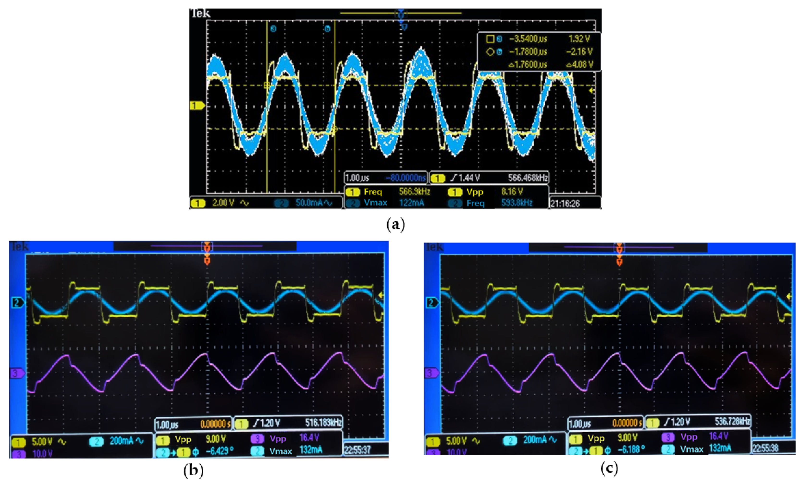
When debugging, first of all, we did not bend the flexible coil at the receiver, but adjusted the voltage and current output from the full-bridge inverter of the transmitter circuit to the same phase and frequency, so that it was equivalent to a negative resistance circuit. As is shown in
Figure 7a, the green line is the current output from the full-bridge inverter, and the blue line is the voltage output from the full-bridge inverter. Then, we adjusted the load at the receiver and the transmitter circuit. Maintaining the negative resistive state of the transmitter, we received a voltage signal in inverse phase with the transmitter voltage at the receiver side. Moreover, within a certain range, no matter how the coil position changed, the amplitude of the voltage received at the receiving end remained unchanged, and only the frequency changed. Therefore, the system was operating in the PT symmetry region. As is shown in
Figure 7b,c, the blue line is the current output from the full-bridge inverter, the yellow line is the voltage output from the full-bridge inverter, and the pink line is the voltage received in the receiver.
On this basis, the efficiency of energy transmission under different degrees of bending of the flexible coil at the receiving end was investigated. According to the simulation results in
Section 2.2, we found that the coupling coefficients of the coils in different bending cases exceed those of the system, so it could be assumed that the system is able to work within the PT-symmetric strong coupling region. We then verified this through an experiment. The experimental setup is shown in
Figure 8. Keeping the distance between the centers of the coils at the transmitting end and the receiving end at 15 mm and separating the coils by a piece of pig skin that represents the human tissue, the flexible receiving coil was placed against a cylinder with different radii to represent the flexible coils with different degrees of bending.
Figure 8a shows the experimental setup in the presence of pig skin, where the transmitting coil is placed under the pig skin, the receiving coil is attached to the cylinder for bending, and the cylinder is held in the hand for testing.
Figure 8b shows the bending of the coil when it is leaned against the cylinder, and the pig skin is removed to especially display the situation clearly. The results are shown in
Figure 8c and
Table 5.
It can be seen that under a 15 mm transmission distance, the transmission efficiency was basically kept constant at about 78% in the strong coupling region, and the output power can be basically maintained constant at about 0.25 W. This could charge the SNM stimulator before operation as well as during operation. From the experiment, the PT symmetry-based WPT system could maintain a constant transmission efficiency and power transmission in the strong coupling region. Therefore, this WPT system is suitable for use in the circuit system of the SNM stimulator.
4. Discussion
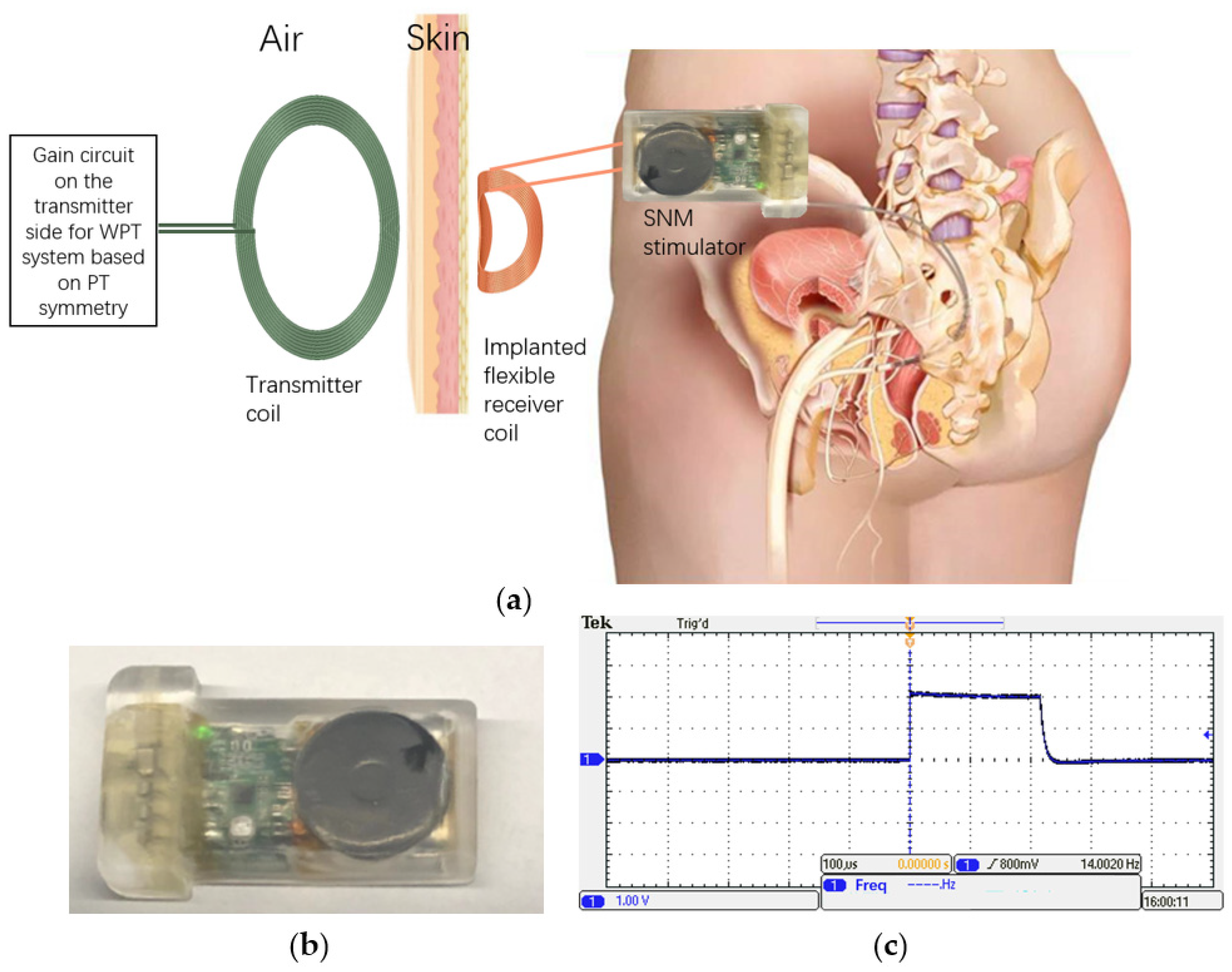
The proposed WPT system can be used in the SNM stimulator as schematically shown in
Figure 9a. The stimulator and the electrode will be implanted in vivo, and the electrode will be placed near the stimulation site on the sacral nerve, which requires long-term intermittent electrical stimulation. The receiver circuit module is directly connected to the stimulator power supply module, but it is not integrated yet. The receiving coil is placed outside the whole stimulator for energy transmission. When the battery is exhausted, wireless charging can be performed by placing the transmitter circuit close to the skin under which the flexible coil of the stimulator is located. The stimulator was designed to be flexible by using flexible printed circuit board, coil printed on PI substrate, and shell made of PDMS. We charged the stimulator by wireless charging based on the PT symmetry theory. The safety standards of this article were developed in accordance with the implantable medical electronic device standard ISO 14117 and IEC 60601 [
13,
14]. After connecting the electrode to the stimulator and making the stimulator work, a 2 V and 14 Hz constant voltage signal could be measured on an oscilloscope at the output of the stimulator, which meets the needs of the SNM stimulator.
Figure 9b illustrates the physical picture of the developed flexible SNM stimulator. We connected the SNM stimulator output electrodes to an oscilloscope, performed tests against the output condition, and measured its output as shown in
Figure 9c. A 2 V and 14 Hz constant voltage signal output could be obtained. The stimulation waveform meets the sacral nerve stimulation demand. The feasibility study demonstrated that the developed PT symmetry mechanism based WPT system is capable of transferring high power wirelessly, and it is sufficient for the proposed LUTD treatment application. Furthermore, studies on system integration, charging temperature regulation, device miniaturization, and flexibility are in progress to clarify all issues pertaining to the practical application of the system.
Compared with common SNM stimulators, the proposed flexible wireless SNM stimulator based on the PT symmetry mechanism replaces the disposable battery of the WPT system, so that a surgery for changing a power-depleted stimulator could be avoided. The PT symmetry principle is introduced into the WPT system to support the charging system to maintain a high charging efficiency despite the spacing of human tissues and to provide stable performance when the transmitting and receiving coils are displaced due to the user’s breathing and movement. Flexible materials are used to design the system to improve a patient’s comfort and make the stimulator biomechanically compatible.
In addition, the proposed WPT system has a higher constant transmission efficiency and a smaller implanted coil, which is suitable for the implanted electrical stimulator, as summarized in
Table 6.


 ,
, 


